WO2017056800A1 - 排気浄化装置 - Google Patents
排気浄化装置 Download PDFInfo
- Publication number
- WO2017056800A1 WO2017056800A1 PCT/JP2016/074771 JP2016074771W WO2017056800A1 WO 2017056800 A1 WO2017056800 A1 WO 2017056800A1 JP 2016074771 W JP2016074771 W JP 2016074771W WO 2017056800 A1 WO2017056800 A1 WO 2017056800A1
- Authority
- WO
- WIPO (PCT)
- Prior art keywords
- filter
- temperature
- dpf
- differential pressure
- upstream
- Prior art date
- Legal status (The legal status is an assumption and is not a legal conclusion. Google has not performed a legal analysis and makes no representation as to the accuracy of the status listed.)
- Ceased
Links
Images


Classifications
-
- F—MECHANICAL ENGINEERING; LIGHTING; HEATING; WEAPONS; BLASTING
- F01—MACHINES OR ENGINES IN GENERAL; ENGINE PLANTS IN GENERAL; STEAM ENGINES
- F01N—GAS-FLOW SILENCERS OR EXHAUST APPARATUS FOR MACHINES OR ENGINES IN GENERAL; GAS-FLOW SILENCERS OR EXHAUST APPARATUS FOR INTERNAL-COMBUSTION ENGINES
- F01N3/00—Exhaust or silencing apparatus having means for purifying, rendering innocuous, or otherwise treating exhaust
- F01N3/02—Exhaust or silencing apparatus having means for purifying, rendering innocuous, or otherwise treating exhaust for cooling, or for removing solid constituents of, exhaust
- F01N3/021—Exhaust or silencing apparatus having means for purifying, rendering innocuous, or otherwise treating exhaust for cooling, or for removing solid constituents of, exhaust by means of filters
- F01N3/023—Exhaust or silencing apparatus having means for purifying, rendering innocuous, or otherwise treating exhaust for cooling, or for removing solid constituents of, exhaust by means of filters using means for regenerating the filters, e.g. by burning trapped particles
-
- F—MECHANICAL ENGINEERING; LIGHTING; HEATING; WEAPONS; BLASTING
- F01—MACHINES OR ENGINES IN GENERAL; ENGINE PLANTS IN GENERAL; STEAM ENGINES
- F01N—GAS-FLOW SILENCERS OR EXHAUST APPARATUS FOR MACHINES OR ENGINES IN GENERAL; GAS-FLOW SILENCERS OR EXHAUST APPARATUS FOR INTERNAL-COMBUSTION ENGINES
- F01N9/00—Electrical control of exhaust gas treating apparatus
- F01N9/002—Electrical control of exhaust gas treating apparatus of filter regeneration
-
- F—MECHANICAL ENGINEERING; LIGHTING; HEATING; WEAPONS; BLASTING
- F01—MACHINES OR ENGINES IN GENERAL; ENGINE PLANTS IN GENERAL; STEAM ENGINES
- F01N—GAS-FLOW SILENCERS OR EXHAUST APPARATUS FOR MACHINES OR ENGINES IN GENERAL; GAS-FLOW SILENCERS OR EXHAUST APPARATUS FOR INTERNAL-COMBUSTION ENGINES
- F01N2560/00—Exhaust systems with means for detecting or measuring exhaust gas components or characteristics
- F01N2560/06—Exhaust systems with means for detecting or measuring exhaust gas components or characteristics the means being a temperature sensor
-
- F—MECHANICAL ENGINEERING; LIGHTING; HEATING; WEAPONS; BLASTING
- F01—MACHINES OR ENGINES IN GENERAL; ENGINE PLANTS IN GENERAL; STEAM ENGINES
- F01N—GAS-FLOW SILENCERS OR EXHAUST APPARATUS FOR MACHINES OR ENGINES IN GENERAL; GAS-FLOW SILENCERS OR EXHAUST APPARATUS FOR INTERNAL-COMBUSTION ENGINES
- F01N2560/00—Exhaust systems with means for detecting or measuring exhaust gas components or characteristics
- F01N2560/08—Exhaust systems with means for detecting or measuring exhaust gas components or characteristics the means being a pressure sensor
-
- F—MECHANICAL ENGINEERING; LIGHTING; HEATING; WEAPONS; BLASTING
- F01—MACHINES OR ENGINES IN GENERAL; ENGINE PLANTS IN GENERAL; STEAM ENGINES
- F01N—GAS-FLOW SILENCERS OR EXHAUST APPARATUS FOR MACHINES OR ENGINES IN GENERAL; GAS-FLOW SILENCERS OR EXHAUST APPARATUS FOR INTERNAL-COMBUSTION ENGINES
- F01N2560/00—Exhaust systems with means for detecting or measuring exhaust gas components or characteristics
- F01N2560/14—Exhaust systems with means for detecting or measuring exhaust gas components or characteristics having more than one sensor of one kind
-
- F—MECHANICAL ENGINEERING; LIGHTING; HEATING; WEAPONS; BLASTING
- F01—MACHINES OR ENGINES IN GENERAL; ENGINE PLANTS IN GENERAL; STEAM ENGINES
- F01N—GAS-FLOW SILENCERS OR EXHAUST APPARATUS FOR MACHINES OR ENGINES IN GENERAL; GAS-FLOW SILENCERS OR EXHAUST APPARATUS FOR INTERNAL-COMBUSTION ENGINES
- F01N2900/00—Details of electrical control or of the monitoring of the exhaust gas treating apparatus
- F01N2900/06—Parameters used for exhaust control or diagnosing
- F01N2900/14—Parameters used for exhaust control or diagnosing said parameters being related to the exhaust gas
- F01N2900/1404—Exhaust gas temperature
-
- F—MECHANICAL ENGINEERING; LIGHTING; HEATING; WEAPONS; BLASTING
- F01—MACHINES OR ENGINES IN GENERAL; ENGINE PLANTS IN GENERAL; STEAM ENGINES
- F01N—GAS-FLOW SILENCERS OR EXHAUST APPARATUS FOR MACHINES OR ENGINES IN GENERAL; GAS-FLOW SILENCERS OR EXHAUST APPARATUS FOR INTERNAL-COMBUSTION ENGINES
- F01N2900/00—Details of electrical control or of the monitoring of the exhaust gas treating apparatus
- F01N2900/06—Parameters used for exhaust control or diagnosing
- F01N2900/16—Parameters used for exhaust control or diagnosing said parameters being related to the exhaust apparatus, e.g. particulate filter or catalyst
-
- Y—GENERAL TAGGING OF NEW TECHNOLOGICAL DEVELOPMENTS; GENERAL TAGGING OF CROSS-SECTIONAL TECHNOLOGIES SPANNING OVER SEVERAL SECTIONS OF THE IPC; TECHNICAL SUBJECTS COVERED BY FORMER USPC CROSS-REFERENCE ART COLLECTIONS [XRACs] AND DIGESTS
- Y02—TECHNOLOGIES OR APPLICATIONS FOR MITIGATION OR ADAPTATION AGAINST CLIMATE CHANGE
- Y02T—CLIMATE CHANGE MITIGATION TECHNOLOGIES RELATED TO TRANSPORTATION
- Y02T10/00—Road transport of goods or passengers
- Y02T10/10—Internal combustion engine [ICE] based vehicles
- Y02T10/40—Engine management systems
Definitions
- One aspect of the present invention relates to an exhaust purification device.
- a device described in Patent Document 1 is known as a conventional exhaust gas purification device.
- the exhaust gas purification device described in Patent Document 1 the exhaust gas flow rate, the DPF differential pressure, the center temperature before and after the DPF, the A / F in the DPF, the soot distribution in the DPF, the exhaust gas heating value, the heating fuel heating value, and the DPF release
- the temperature distribution in the DPF is estimated based on the amount of heat
- the DPF temperature gradient is calculated based on the temperature distribution in the DPF
- the target temperature during PM regeneration The PM regeneration is continued based on the target temperature.
- PM regeneration is performed based on the differential pressure (filter differential pressure) between the pressure on the upstream side of the DPF and the pressure on the downstream side of the DPF.
- filter differential pressure filter differential pressure
- An object of one aspect of the present invention is to provide an exhaust purification device capable of obtaining a highly accurate filter differential pressure even when there is a temperature gradient in the filter.
- An exhaust emission control device is an exhaust emission control device that purifies exhaust gas discharged from an internal combustion engine, a filter that collects particulate matter contained in the exhaust gas, and fuel that supplies fuel to the filter A supply unit; a differential pressure detection unit that detects a differential pressure between a pressure upstream of the filter and a pressure downstream of the filter; a first temperature detection unit that detects an exhaust gas temperature upstream of the filter; and a downstream of the filter A second temperature detection unit that detects the exhaust temperature on the side, an exhaust temperature upstream of the filter detected by the first temperature detection unit, and an exhaust temperature downstream of the filter detected by the second temperature detection unit Based on the temperature gradient in the filter estimated by the temperature gradient estimator and the temperature gradient in the filter estimated by the temperature gradient estimator, the area ratio of the upstream block and the downstream block of the filter is calculated.
- the area ratio calculation section calculates the differential pressure between the pressure upstream of the filter detected by the differential pressure detector and the pressure downstream of the filter, based on the area ratio of the upstream block and the downstream block of the filter, Based on the differential pressure correction unit that calculates the corrected differential pressure of the filter and the corrected differential pressure of the filter calculated by the differential pressure correction unit, the fuel supply unit is controlled so that particulate matter deposited on the filter is burned by the fuel A playback control unit.
- the temperature gradient in the filter is estimated based on the exhaust temperature upstream of the filter and the exhaust temperature downstream of the filter, and based on the temperature gradient in the filter, The area ratio of the upstream block and the downstream block is calculated. Then, based on the exhaust gas temperature upstream of the filter, the exhaust gas temperature downstream of the filter, and the area ratio of the upstream block and downstream block of the filter, the pressure upstream of the filter detected by the differential pressure detector
- the corrected differential pressure of the filter is calculated by correcting the differential pressure with the pressure on the downstream side of the filter.
- the temperature gradient estimation unit divides the filter into a plurality of regions along the direction in which the exhaust gas flows, and based on the exhaust temperature upstream of the filter and the exhaust temperature downstream of the filter, The region temperature may be estimated, and the region ratio calculation unit may calculate the region ratio of the upstream block and the downstream block of the filter based on the temperatures of the plurality of regions.
- the temperature gradient in the filter can be reliably estimated using a known temperature propagation model.
- the area ratio between the upstream block and the downstream block of the filter can be easily calculated by a predetermined calculation formula.
- the differential pressure correction unit corrects the differential pressure between the pressure upstream of the filter and the pressure downstream of the filter based on the exhaust temperature upstream of the filter, thereby correcting the first differential pressure temperature correction value. And calculating the second differential pressure temperature correction value by correcting the differential pressure between the pressure upstream of the filter and the pressure downstream of the filter based on the exhaust temperature downstream of the filter. A value obtained by multiplying the first differential pressure temperature correction value by the area ratio of the upstream block of the filter and a value obtained by multiplying the second differential pressure temperature correction value and the area ratio of the downstream block of the filter are added to obtain a filter.
- the corrected differential pressure may be calculated. In this case, the corrected differential pressure of the filter can be easily calculated using a predetermined calculation formula.
- FIG. 1 is a schematic configuration diagram illustrating an exhaust emission control device according to an embodiment.
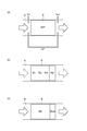
- FIGS. 2A to 2C are diagrams showing an approximate model for estimating the temperature gradient in the DPF and calculating the area ratio of the upstream block and the downstream block of the DPF.
- FIG. 3 is a graph showing an example of the area ratio of the upstream block and the downstream block of the DPF.
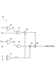
- FIG. 4 is a block diagram illustrating a function of the differential pressure correction unit illustrated in FIG.
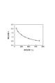
- FIG. 5 is a graph showing a temperature correction map used in the correction coefficient acquisition unit shown in FIG.
- FIG. 6 is a diagram illustrating detection data used when calculating a corrected DPF differential pressure in the related art.
- FIG. 7 is a block diagram illustrating a function of a differential pressure correction unit that calculates a corrected DPF differential pressure in the related art.
- FIG. 1 is a schematic configuration diagram showing an exhaust purification device according to an embodiment.
- an exhaust emission control device 1 of this embodiment is mounted on a vehicle.
- the exhaust purification device 1 purifies exhaust gas discharged from a diesel engine (hereinafter simply referred to as an engine) 2 that is an internal combustion engine.
- the engine 2 has a plurality of injectors 3 that inject fuel into a plurality of cylinders (not shown).
- the exhaust purification apparatus 1 includes a diesel oxidation catalyst (DOC) 5 and a diesel exhaust particulate removal filter (DPF: Diesel) disposed in order from an upstream side to a downstream side in an exhaust passage 4 connected to an engine 2. Particulate Filter) 6.
- the DOC 5 oxidizes and removes particulate matter (PM) contained in the exhaust gas.
- the DPF 6 collects PM contained in the exhaust gas.
- the DPF 6 is made of cordierite or SiC.
- the exhaust purification device 1 includes a fuel addition valve 7 that is disposed on the upstream side of the DOC 5 in the exhaust passage 4 and that adds fuel to the exhaust passage 4.
- the fuel added from the fuel addition valve 7 is mainly used as a reducing agent when the DPF 6 is regenerated.
- the regeneration of the DPF 6 is to burn the PM deposited on the DPF 6 with a high-temperature fuel.
- the fuel addition valve 7 constitutes a fuel supply unit that supplies fuel to the DPF 6.
- the exhaust purification device 1 includes a differential pressure sensor 8 (differential pressure detection unit) that detects a differential pressure (a DPF differential pressure) between a pressure upstream of the DPF 6 and a pressure downstream of the DPF 6, and an upstream side of the DPF 6.
- a temperature sensor 9 first temperature detection unit
- a temperature sensor 10 second temperature detection unit
- a controller 11 connected to the sensors 9 and 10 is provided.
- the controller 11 inputs detection signals from the differential pressure sensor 8 and the temperature sensors 9 and 10, performs predetermined processing, and controls the fuel addition valve 7 so as to perform regeneration processing of the DPF 6.
- the controller 11 includes a temperature gradient estimation unit 12, a region ratio calculation unit 13, a differential pressure correction unit 14, and a regeneration control unit 15.
- the temperature gradient estimation unit 12 estimates a temperature gradient in the DPF 6 based on the exhaust temperature upstream of the DPF 6 detected by the temperature sensor 9 and the exhaust temperature downstream of the DPF 6 detected by the temperature sensor 10.
- the exhaust temperature on the upstream side of the DPF 6 is equal to the input temperature Tin of the DPF 6, and the exhaust temperature on the downstream side of the DPF 6 is equal to the output temperature Tout of the DPF 6 (see FIG. 2A).
- the temperature gradient estimation unit 12 divides the DPF 6 into a plurality of regions along the direction in which the exhaust gas flows (exhaust direction), as shown in FIG. At this time, the dimension of each area
- the DPF 6 is divided into four regions R1 to R4 along the exhaust direction.
- the temperature gradient estimation unit 12 estimates the temperatures T1 to T4 of the respective regions R1 to R4 of the DPF 6 using, for example, a known DPF temperature propagation model.
- the DPF temperature propagation model is a model for estimating the temperature propagation state in the DPF 6 by inputting parameters such as the input temperature Tin of the DPF 6, the output temperature Tout of the DPF 6, the flow rate of the exhaust gas, and the heat capacity of the DPF 6.
- the temperature T1 of the region R1 is the input temperature Tin of the DPF 6
- the temperature T4 of the region R4 is the output temperature Tout of the DPF 6.
- the area ratio calculation unit 13 calculates the area ratio of the upstream block Bin and the downstream block Bout of the DPF 6 shown in FIG. 2C based on the temperature gradient in the DPF 6 estimated by the temperature gradient estimation unit 12. .
- the area ratio between the upstream block Bin and the downstream block Bout of the DPF 6 is a ratio of the dimensions in the exhaust direction of the upstream block Bin and the downstream block Bout of the DPF 6.
- the upstream block Bin is a block located at least upstream when the DPF 6 is divided into two blocks along the exhaust direction, and the downstream block Bout is at least when the DPF 6 is divided into two blocks in the same manner. This is a block located on the downstream side. That is, the downstream block Bout is located downstream of the upstream block Bin.
- the upstream block Bin and the downstream block Bout are set by the regions R1 to R4 of the DPF 6.
- the region ratio calculation unit 13 calculates an average value (average temperature) of the temperatures of the regions R1 to R4 of the DPF 6.
- the area ratio calculation unit 13 calculates the area ratio ⁇ of one of the upstream block Bin and the downstream block Bout of the DPF 6 using the following formula.
- Area ratio ⁇ (average temperature-minimum temperature) / (maximum temperature-minimum temperature)
- the minimum temperature is the lowest temperature among the temperatures of the respective regions R1 to R4 of the DPF 6.
- the maximum temperature is the highest temperature among the temperatures of the regions R1 to R4 of the DPF 6.
- the region ratio ⁇ is equal to the size of the upstream block Bin in the exhaust direction and the downstream side. This is the dimension in the exhaust direction of the upstream block Bin relative to the sum of the dimensions in the exhaust direction of the side block Bout.
- the region ratio ⁇ is equal to the size of the upstream block Bin in the exhaust direction and the downstream block Bout. This is the dimension in the exhaust direction of the downstream block Bout with respect to the sum of the dimensions in the exhaust direction.
- the average temperature of the regions R1 to R4 is 275 ° C.
- the area ratio ⁇ of the upstream block Bin of the DPF 6 is 0.75
- the area ratio ⁇ of the downstream block Bout of the DPF 6 is 0.25. That is, the area ratio between the upstream block Bin and the downstream block Bout is 3: 1.
- the maximum temperature of 300 ° C. is 100%
- the minimum temperature of 200 ° C. is 0%.
- the differential pressure correction unit 14 detects the exhaust temperature upstream of the DPF 6 detected by the temperature sensor 9, the exhaust temperature downstream of the DPF 6 detected by the temperature sensor 10, and the DPF 6 calculated by the region ratio calculation unit 13. Based on the area ratio of the upstream block Bin and the downstream block Bout, the differential pressure between the upstream pressure of the DPF 6 detected by the differential pressure sensor 8 and the downstream pressure of the DPF 6 (hereinafter, detected DPF differential pressure). Is corrected, the corrected differential pressure of the DPF 6 (hereinafter, corrected DPF differential pressure) is calculated.
- the differential pressure correction unit 14 includes a correction coefficient acquisition unit 16, a coefficient multiplication unit 17, a correction coefficient acquisition unit 18, a coefficient multiplication unit 19, a ratio multiplication unit 20, and a ratio multiplication unit. 21 and an adder 22.
- the correction coefficient acquisition unit 16 acquires a correction coefficient Kin corresponding to the upstream exhaust temperature of the DPF 6 detected by the temperature sensor 9, that is, the input temperature Tin of the DPF 6, using the correction coefficient map shown in FIG.
- the coefficient multiplier 17 multiplies the detected DPF differential pressure ⁇ P and the correction coefficient Kin to calculate a first differential pressure temperature correction value. For example, when the input temperature Tin of the DPF 6 is 300 ° C., the correction coefficient Kin is 1.0, so that the detected DPF differential pressure ⁇ P is multiplied by 1.0.
- the correction coefficient acquisition unit 18 acquires the correction coefficient Kout corresponding to the exhaust temperature downstream of the DPF 6 detected by the temperature sensor 10, that is, the output temperature Tout of the DPF 6, using the temperature correction map shown in FIG.
- the coefficient multiplier 19 multiplies the detected DPF differential pressure ⁇ P and the correction coefficient Kout to calculate a second differential pressure temperature correction value. For example, when the output temperature Tout of the DPF 6 is 200 ° C., the correction coefficient Kout is 1.25, so that the detected DPF differential pressure ⁇ P is multiplied by 1.25.
- the reason why the detected DPF differential pressure ⁇ P is temperature-corrected is to consider that the viscosity and density of the exhaust gas change depending on the exhaust temperature (the temperature of the exhaust gas).
- the ratio multiplying unit 20 multiplies the first differential pressure temperature correction value calculated by the coefficient multiplying unit 17 by the region ratio of the upstream block Bin of the DPF 6 calculated by the region ratio calculating unit 13 to obtain the first differential pressure.
- a ratio correction value is calculated.
- the ratio multiplication unit 20 multiplies the first differential pressure temperature correction value by the region ratio ⁇ , and the output temperature Tout of the DPF 6 becomes the input temperature Tin of the DPF 6. Is higher, the first differential pressure temperature correction value is multiplied by the region ratio ⁇ .
- the ratio multiplier 21 multiplies the second differential pressure temperature correction value calculated by the coefficient multiplier 19 and the area ratio of the downstream block Bout of the DPF 6 calculated by the area ratio calculator 13 to obtain the second differential pressure.
- a ratio correction value is calculated.
- the ratio multiplier 21 multiplies the second differential pressure correction value by the region ratio ⁇ , and the output temperature Tout of the DPF 6 becomes the input temperature Tin of the DPF 6. Is higher than the second differential pressure temperature correction value and the region ratio ⁇ .
- the adding unit 22 adds the first differential pressure ratio correction value and the second differential pressure ratio correction value to calculate a corrected DPF differential pressure.
- the differential pressure correction unit 14 calculates the corrected DPF differential pressure by the following equation (A), and the output temperature Tout of the DPF 6 is the input of the DPF 6.
- the corrected DPF differential pressure is calculated by the following equation (B).
- Corrected DPF differential pressure ⁇ ⁇ Kin ⁇ ⁇ P + ⁇ ⁇ Kout ⁇ ⁇ P (A)
- Corrected DPF differential pressure ⁇ ⁇ Kin ⁇ ⁇ P + ⁇ ⁇ Kout ⁇ ⁇ P (B)
- the regeneration control unit 15 controls the fuel addition valve 7 to perform PM regeneration based on the corrected DPF differential pressure calculated by the differential pressure correcting unit 14. Specifically, the regeneration control unit 15 controls the fuel addition valve 7 so that fuel is added from the fuel addition valve 7 to perform PM regeneration when the corrected DPF differential pressure reaches a predetermined threshold value. To do.
- the differential pressure correction unit 50 corrects the differential pressure (detected DPF differential pressure) ⁇ P between the pressure on the upstream side of the DPF 6 and the pressure on the downstream side of the DPF 6 based on the input temperature Tin of the DPF 6, thereby correcting the DPF. Calculate the differential pressure.
- the differential pressure correction unit 50 includes a correction coefficient acquisition unit 51 and a coefficient multiplication unit 52.
- the correction coefficient acquisition unit 51 acquires a correction coefficient K corresponding to the input temperature Tin of the DPF 6 using the correction coefficient map shown in FIG.
- the coefficient multiplier 52 multiplies the detected DPF differential pressure ⁇ P and the correction coefficient K to calculate a corrected DPF differential pressure.
- the corrected DPF differential pressure can be calculated by the differential pressure correction unit 50 shown in FIG.
- the temperature gradient in the DPF 6 is estimated based on the exhaust temperature upstream of the DPF 6 and the exhaust temperature downstream of the DPF 6, and the upstream of the DPF 6 is estimated based on the temperature gradient in the DPF 6.
- the area ratio of the side block Bin and the downstream block Bout is calculated.
- the detected DPF differential pressure is corrected based on the exhaust gas temperature upstream of the DPF 6, the exhaust gas temperature downstream of the DPF 6, and the area ratio of the upstream block Bin and the downstream block Bout of the DPF 6.
- the differential pressure is calculated.
- the DPF 6 is divided into a plurality of regions along the flow direction of the exhaust gas, and the temperatures of the plurality of regions are estimated based on the exhaust gas temperature upstream of the DPF 6 and the exhaust gas temperature downstream of the DPF 6. Based on the temperature of the region, the region ratio of the upstream block Bin and the downstream block Bout of the DPF 6 is calculated. Thereby, for example, the temperature gradient in the DPF 6 can be reliably estimated using a known DPF temperature propagation model. Further, the area ratio of the upstream block Bin and the downstream block Bout of the DPF 6 can be easily calculated by a predetermined calculation formula.
- the differential pressure between the upstream pressure of the DPF 6 and the downstream pressure of the DPF 6 is corrected, and a first differential pressure temperature correction value is calculated.
- the differential pressure between the upstream pressure of the DPF 6 and the downstream pressure of the DPF 6 is corrected to calculate a second differential pressure temperature correction value.
- a value obtained by multiplying the first differential pressure correction value by the region ratio of the upstream block Bin of the DPF 6 and a value obtained by multiplying the second differential pressure temperature correction value by the region ratio of the downstream block Bout of the DPF 6 are obtained.
- the corrected differential pressure of DPF 6 is calculated by adding. Thereby, the corrected DPF differential pressure can be easily calculated by a predetermined calculation formula.
- the DPF 6 is regenerated by adding fuel from the fuel addition valve 7.
- the embodiment is not limited to this, and the cylinder (not shown) is not limited to the injector 3 disposed in the engine 2.
- the DPF 6 may be regenerated by injecting the fuel into ().
- the injector 3 constitutes a fuel supply unit that supplies fuel to the DPF 6.
- the exhaust purification apparatus 1 of the said embodiment is equipped with DPF6 as a filter
- one side of this invention is exhaust_gas
Landscapes
- Engineering & Computer Science (AREA)
- Chemical & Material Sciences (AREA)
- Combustion & Propulsion (AREA)
- Mechanical Engineering (AREA)
- General Engineering & Computer Science (AREA)
- Processes For Solid Components From Exhaust (AREA)
Abstract
排気浄化装置(1)は、DPF(6)の上流側の排気温度とDPFの下流側の排気温度とに基づいてDPF内の温度勾配を推定する温度勾配推定部(12)と、DPF内の温度勾配に基づいてDPFの上流側ブロック及び下流側ブロックの領域比率を算出する領域比率算出部(13)と、DPFの上流側の排気温度とDPFの下流側の排気温度とDPFの上流側ブロック及び下流側ブロックの領域比率とに基づいて、差圧センサ(8)により検出されたDPFの上流側の圧力とDPFの下流側の圧力との差圧を補正することで、DPFの補正差圧を算出する差圧補正部(14)と、DPFの補正差圧に基づいて、DPFに堆積したPMを燃料により燃焼させるように燃料添加弁(7)を制御する再生制御部(15)と、を備える。
Description
本発明の一側面は、排気浄化装置に関する。
従来の排気浄化装置としては、例えば特許文献1に記載されている装置が知られている。特許文献1に記載の排気浄化装置においては、排気ガス流量、DPF差圧、DPF前後中心温度、DPF内A/F、DPF内Soot分布、排気ガス発熱量、昇温用燃料発熱量及びDPF放熱量に基づいてDPF内の温度分布を推定し、そのDPF内の温度分布に基づいてDPF温度勾配を算出し、そのDPF温度勾配が危険値を超えている場合には、PM再生時における目標温度を下げ、その目標温度に基づいてPM再生を継続する。
PM再生は、DPFの上流側の圧力とDPFの下流側の圧力との差圧(フィルタ差圧)に基づいて実施される。ところで、特にショベル及び掘削機等のような作業車両では、作業の特性から負荷変動が多いため、DPF内の温度勾配が大きくなる。DPF内の温度勾配が大きいと、高精度のフィルタ差圧を得ることが困難である。
本発明の一側面は、フィルタ内の温度勾配があっても、高精度のフィルタ差圧を得ることができる排気浄化装置を提供することを目的とする。
本発明の一側面に係る排気浄化装置は、内燃機関から排出される排気ガスを浄化する排気浄化装置において、排気ガスに含まれる粒子状物質を捕集するフィルタと、フィルタに燃料を供給する燃料供給部と、フィルタの上流側の圧力とフィルタの下流側の圧力との差圧を検出する差圧検出部と、フィルタの上流側の排気温度を検出する第1温度検出部と、フィルタの下流側の排気温度を検出する第2温度検出部と、第1温度検出部により検出されたフィルタの上流側の排気温度と第2温度検出部により検出されたフィルタの下流側の排気温度とに基づいて、フィルタ内の温度勾配を推定する温度勾配推定部と、温度勾配推定部により推定されたフィルタ内の温度勾配に基づいて、フィルタの上流側ブロック及び下流側ブロックの領域比率を算出する領域比率算出部と、第1温度検出部により検出されたフィルタの上流側の排気温度と、第2温度検出部により検出されたフィルタの下流側の排気温度と、領域比率算出部により算出されたフィルタの上流側ブロック及び下流側ブロックの領域比率とに基づいて、差圧検出部により検出されたフィルタの上流側の圧力とフィルタの下流側の圧力との差圧を補正することで、フィルタの補正差圧を算出する差圧補正部と、差圧補正部により算出されたフィルタの補正差圧に基づいて、フィルタに堆積した粒子状物質を燃料により燃焼させるように燃料供給部を制御する再生制御部とを備える。
このような排気浄化装置においては、フィルタの上流側の排気温度とフィルタの下流側の排気温度とに基づいて、フィルタ内の温度勾配が推定され、そのフィルタ内の温度勾配に基づいて、フィルタの上流側ブロック及び下流側ブロックの領域比率が算出される。そして、フィルタの上流側の排気温度とフィルタの下流側の排気温度とフィルタの上流側ブロック及び下流側ブロックの領域比率とに基づいて、差圧検出部により検出されたフィルタの上流側の圧力とフィルタの下流側の圧力との差圧が補正されることで、フィルタの補正差圧が算出される。これにより、フィルタ内の温度勾配があっても、高精度のフィルタ差圧(フィルタの上流側の圧力とフィルタの下流側の圧力との差圧)を得ることができる。
一実施形態において、温度勾配推定部は、フィルタを排気ガスが流れる方向に沿って複数の領域に分割し、フィルタの上流側の排気温度とフィルタの下流側の排気温度とに基づいて、複数の領域の温度を推定し、領域比率算出部は、複数の領域の温度に基づいて、フィルタの上流側ブロック及び下流側ブロックの領域比率を算出してもよい。この場合には、例えば既知の温度伝播モデルを用いてフィルタ内の温度勾配を確実に推定することができる。また、フィルタの上流側ブロック及び下流側ブロックの領域比率を所定の算出式により簡単に算出することができる。
一実施形態において、差圧補正部は、フィルタの上流側の排気温度に基づいて、フィルタの上流側の圧力とフィルタの下流側の圧力との差圧を補正して第1差圧温度補正値を算出すると共に、フィルタの下流側の排気温度に基づいて、フィルタの上流側の圧力とフィルタの下流側の圧力との差圧を補正して第2差圧温度補正値を算出した後、第1差圧温度補正値とフィルタの上流側ブロックの領域比率とを乗算した値と、第2差圧温度補正値とフィルタの下流側ブロックの領域比率とを乗算した値とを加算して、フィルタの補正差圧を算出してもよい。この場合には、フィルタの補正差圧を所定の算出式により簡単に算出することができる。
本発明の一側面によれば、フィルタ内の温度勾配があっても、高精度のフィルタ差圧を得ることができる。
以下、一実施形態について、図面を参照して詳細に説明する。
図1は、一実施形態に係る排気浄化装置を示す概略構成図である。図1において、本実施形態の排気浄化装置1は、車両に搭載されている。排気浄化装置1は、内燃機関であるディーゼルエンジン(以下、単にエンジンという)2から排出される排気ガスを浄化する。エンジン2は、複数の気筒(図示せず)にそれぞれ燃料を噴射する複数のインジェクタ3を有している。
排気浄化装置1は、エンジン2に接続された排気通路4に上流側から下流側に向けて順に配設されたディーゼル酸化触媒(DOC:Diesel Oxidation Catalyst)5及びディーゼル排気微粒子除去フィルタ(DPF:Diesel Particulate Filter)6を備えている。DOC5は、排気ガスに含まれる粒子状物質(PM:Particulate Matter)を酸化して除去する。DPF6は、排気ガスに含まれるPMを捕集する。DPF6は、コージェライトまたはSiC等で形成されている。
また、排気浄化装置1は、排気通路4におけるDOC5の上流側に配設され、排気通路4に燃料を添加する燃料添加弁7を備えている。燃料添加弁7から添加される燃料は、主としてDPF6の再生を行う際に還元剤として使用される。DPF6の再生とは、DPF6に堆積したPMを高温の燃料により燃焼させることである。燃料添加弁7は、DPF6に燃料を供給する燃料供給部を構成している。
また、排気浄化装置1は、DPF6の上流側の圧力とDPF6の下流側の圧力との差圧(DPF差圧)を検出する差圧センサ8(差圧検出部)と、DPF6の上流側の排気温度を検出する温度センサ9(第1温度検出部)と、DPF6の下流側の排気温度を検出する温度センサ10(第2温度検出部)と、燃料添加弁7、差圧センサ8及び温度センサ9,10と接続されたコントローラ11とを備えている。
コントローラ11は、差圧センサ8及び温度センサ9,10の検出信号を入力し、所定の処理を行い、DPF6の再生処理を実施するように燃料添加弁7を制御する。コントローラ11は、温度勾配推定部12と、領域比率算出部13と、差圧補正部14と、再生制御部15とを有している。
温度勾配推定部12は、温度センサ9により検出されたDPF6の上流側の排気温度と温度センサ10により検出されたDPF6の下流側の排気温度とに基づいて、DPF6内の温度勾配を推定する。DPF6の上流側の排気温度は、DPF6の入力温度Tinに等しく、DPF6の下流側の排気温度は、DPF6の出力温度Toutに等しい(図2(a)参照)。
温度勾配推定部12は、図2(b)に示されるように、DPF6を排気ガスが流れる方向(排気方向)に沿って複数の領域に分割する。このとき、各領域の排気方向の寸法は等しい。ここでは、DPF6は、排気方向に沿って4つの領域R1~R4に分割される。
そして、温度勾配推定部12は、例えば既知のDPF温度伝播モデルを用いて、DPF6の各領域R1~R4の温度T1~T4を推定する。DPF温度伝播モデルは、DPF6の入力温度Tin、DPF6の出力温度Tout、排気ガスの流量及びDPF6の熱容量等のパラメータを入力して、DPF6内の温度伝播状況を推定するためのモデルである。なお、図2(b)において、領域R1の温度T1はDPF6の入力温度Tinであり、領域R4の温度T4はDPF6の出力温度Toutである。
領域比率算出部13は、温度勾配推定部12により推定されたDPF6内の温度勾配に基づいて、図2(c)に示されるDPF6の上流側ブロックBin及び下流側ブロックBoutの領域比率を算出する。DPF6の上流側ブロックBin及び下流側ブロックBoutの領域比率は、DPF6の上流側ブロックBin及び下流側ブロックBoutの排気方向の寸法の比率である。上流側ブロックBinは、DPF6を排気方向に沿って2つのブロックに分けた場合の少なくとも上流側に位置するブロックであり、下流側ブロックBoutは、DPF6を同様に2つのブロックに分けた場合の少なくとも下流側に位置するブロックである。つまり、下流側ブロックBoutは、上流側ブロックBinよりも下流側に位置している。上流側ブロックBin及び下流側ブロックBoutは、DPF6の領域R1~R4によって設定される。
領域比率算出部13は、DPF6の各領域R1~R4の温度の平均値(平均温度)を算出する。領域比率算出部13は、下記式を用いて、DPF6の上流側ブロックBin及び下流側ブロックBoutの何れか一方の領域比率αを算出する。
領域比率α=(平均温度-最小温度)/(最大温度-最小温度)
領域比率α=(平均温度-最小温度)/(最大温度-最小温度)
なお、最小温度は、DPF6の各領域R1~R4の温度のうち最も低い温度である。最大温度は、DPF6の各領域R1~R4の温度のうち最も高い温度である。
ここで、領域R1の温度T1(DPF6の入力温度Tin)が領域R4の温度T4(DPF6の出力温度Tout)よりも高いときは、領域比率αは、上流側ブロックBinの排気方向の寸法と下流側ブロックBoutの排気方向の寸法との合計に対する上流側ブロックBinの排気方向の寸法である。領域R4の温度T4(DPF6の出力温度Tout)が領域R1の温度T1(DPF6の入力温度Tin)よりも高いときは、領域比率αは、上流側ブロックBinの排気方向の寸法と下流側ブロックBoutの排気方向の寸法との合計に対する下流側ブロックBoutの排気方向の寸法である。
また、領域比率算出部13は、下記式を用いて、DPF6の上流側ブロックBin及び下流側ブロックBoutの他方の領域比率βを算出する。
領域比率β=1-α
領域比率β=1-α
例えば、領域R1~R3の温度を300℃、領域R4の温度を200℃とした場合、領域R1~R4の平均温度は275℃となる。そして、図3に示されるように、DPF6の上流側ブロックBinの領域比率αは0.75となり、DPF6の下流側ブロックBoutの領域比率βは0.25となる。つまり、上流側ブロックBinと下流側ブロックBoutとの領域比は、3:1となる。なお、図3では、最大温度である300℃を100%、最小温度である200℃を0%としている。このとき、図2(c)に示されるように、DPF6の領域R1~R3が上流側ブロックBinとなり、DPF6の領域R4が下流側ブロックBoutとなる。
差圧補正部14は、温度センサ9により検出されたDPF6の上流側の排気温度と、温度センサ10により検出されたDPF6の下流側の排気温度と、領域比率算出部13により算出されたDPF6の上流側ブロックBin及び下流側ブロックBoutの領域比率とに基づいて、差圧センサ8により検出されたDPF6の上流側の圧力とDPF6の下流側の圧力との差圧(以下、検出DPF差圧)を補正することで、DPF6の補正差圧(以下、補正DPF差圧)を算出する。
差圧補正部14は、図4に示されるように、補正係数取得部16と、係数乗算部17と、補正係数取得部18と、係数乗算部19と、比率乗算部20と、比率乗算部21と、加算部22とを有している。
補正係数取得部16は、図5に示される補正係数マップを用いて、温度センサ9により検出されたDPF6の上流側の排気温度つまりDPF6の入力温度Tinに対応する補正係数Kinを取得する。係数乗算部17は、検出DPF差圧ΔPと補正係数Kinとを乗算して、第1差圧温度補正値を算出する。例えば、DPF6の入力温度Tinが300℃の場合には、補正係数Kinは1.0であるため、検出DPF差圧ΔPと1.0とを乗算する。
補正係数取得部18は、図5に示される温度補正マップを用いて、温度センサ10により検出されたDPF6の下流側の排気温度つまりDPF6の出力温度Toutに対応する補正係数Koutを取得する。係数乗算部19は、検出DPF差圧ΔPと補正係数Koutとを乗算して、第2差圧温度補正値を算出する。例えば、DPF6の出力温度Toutが200℃の場合には、補正係数Koutは1.25であるため、検出DPF差圧ΔPと1.25とを乗算する。
なお、検出DPF差圧ΔPを温度補正する理由は、排気温度(排気ガスの温度)によって排気ガスの粘度及び密度が変わることを考慮するためである。
比率乗算部20は、係数乗算部17により算出された第1差圧温度補正値と領域比率算出部13により算出されたDPF6の上流側ブロックBinの領域比率とを乗算して、第1差圧比率補正値を算出する。比率乗算部20は、DPF6の入力温度TinがDPF6の出力温度Toutよりも高いときは、第1差圧温度補正値と領域比率αとを乗算し、DPF6の出力温度Tout がDPF6の入力温度Tinよりも高いときは、第1差圧温度補正値と領域比率βとを乗算する。
比率乗算部21は、係数乗算部19により算出された第2差圧温度補正値と領域比率算出部13により算出されたDPF6の下流側ブロックBoutの領域比率とを乗算して、第2差圧比率補正値を算出する。比率乗算部21は、DPF6の入力温度TinがDPF6の出力温度Toutよりも高いときは、第2差圧温度補正値と領域比率βとを乗算し、DPF6の出力温度Tout がDPF6の入力温度Tinよりも高いときは、第2差圧温度補正値と領域比率αとを乗算する。
加算部22は、第1差圧比率補正値と第2差圧比率補正値とを加算して、補正DPF差圧を算出する。
以上により、差圧補正部14は、DPF6の入力温度TinがDPF6の出力温度Toutよりも高いときは、下記(A)式により補正DPF差圧を算出し、DPF6の出力温度Tout がDPF6の入力温度Tinよりも高いときは、下記(B)式により補正DPF差圧を算出する。なお、DPF6の入力温度TinとDPF6の出力温度Toutとが同じであるときは、(A)式及び(B)式のいずれを用いてもよい。
補正DPF差圧=α×Kin×ΔP+β×Kout×ΔP …(A)
補正DPF差圧=β×Kin×ΔP+α×Kout×ΔP …(B)
補正DPF差圧=α×Kin×ΔP+β×Kout×ΔP …(A)
補正DPF差圧=β×Kin×ΔP+α×Kout×ΔP …(B)
再生制御部15は、差圧補正部14により算出された補正DPF差圧に基づいて、PM再生を行うように燃料添加弁7を制御する。具体的には、再生制御部15は、補正DPF差圧が予め決められた閾値に達したときに、PM再生を行うべく、燃料添加弁7から燃料を添加させるように燃料添加弁7を制御する。
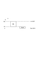
ところで、従来では、図6及び図7に示されるように、DPF6の入力温度Tinと、DPF6の上流側の圧力とDPF6の下流側の圧力との差圧ΔPとが検出される。そして、差圧補正部50は、DPF6の入力温度Tinに基づいて、DPF6の上流側の圧力とDPF6の下流側の圧力との差圧(検出DPF差圧)ΔPを補正することで、補正DPF差圧を算出する。
差圧補正部50は、補正係数取得部51と、係数乗算部52とを有している。補正係数取得部51は、図5に示される補正係数マップを用いて、DPF6の入力温度Tinに対応する補正係数Kを取得する。係数乗算部52は、検出DPF差圧ΔPと補正係数Kとを乗算して、補正DPF差圧を算出する。
例えば乗用車では、主な目的が走行であるため、排気流量及び温度が均一となる条件が多くなる。従って、DPF6内の温度が全体的にほぼ均一になるため、図7に示される差圧補正部50によって補正DPF差圧を算出することが可能である。
しかし、ショベル及び掘削機等の作業車両では、作業の特性から負荷変動が多いため、排気流量及び温度が均一に安定した条件が得られにくく、DPF6内の温度勾配が発生する。従って、図7に示される差圧補正部50によって補正DPF差圧を正確に算出することはできない。
これに対し本実施形態では、DPF6の上流側の排気温度とDPF6の下流側の排気温度とに基づいて、DPF6内の温度勾配が推定され、そのDPF6内の温度勾配に基づいて、DPF6の上流側ブロックBin及び下流側ブロックBoutの領域比率が算出される。そして、DPF6の上流側の排気温度とDPF6の下流側の排気温度とDPF6の上流側ブロックBin及び下流側ブロックBoutの領域比率とに基づいて、検出DPF差圧が補正されることで、補正DPF差圧が算出される。これにより、DPF6内の温度勾配があっても、高精度のDPF差圧を得ることができる。
また、DPF6を排気ガスが流れる方向に沿って複数の領域に分割し、DPF6の上流側の排気温度とDPF6の下流側の排気温度とに基づいて、複数の領域の温度が推定され、その複数の領域の温度に基づいて、DPF6の上流側ブロックBin及び下流側ブロックBoutの領域比率が算出される。これにより、例えば既知のDPF温度伝播モデルを用いてDPF6内の温度勾配を確実に推定することができる。また、DPF6の上流側ブロックBin及び下流側ブロックBoutの領域比率を所定の算出式により簡単に算出することができる。
さらに、DPF6の上流側の排気温度に基づいて、DPF6の上流側の圧力とDPF6の下流側の圧力との差圧が補正されて、第1差圧温度補正値が算出されると共に、DPF6の下流側の排気温度に基づいて、DPF6の上流側の圧力とDPF6の下流側の圧力との差圧が補正されて、第2差圧温度補正値が算出される。そして、第1差圧温度補正値とDPF6の上流側ブロックBinの領域比率とを乗算した値と、第2差圧温度補正値とDPF6の下流側ブロックBoutの領域比率とを乗算した値とが加算されて、DPF6の補正差圧が算出される。これにより、補正DPF差圧を所定の算出式により簡単に算出することができる。
なお、本発明の一側面は、上記実施形態には限定されない。例えば、上記実施形態では、燃料添加弁7から燃料を添加させることにより、DPF6の再生を行っているが、特にその形態には限られず、エンジン2に配置されたインジェクタ3から気筒(図示せず)に燃料を噴射することにより、DPF6の再生を行ってもよい。この場合には、インジェクタ3は、DPF6に燃料を供給する燃料供給部を構成することとなる。
また、上記実施形態の排気浄化装置1は、フィルタとしてDPF6を備えているが、本発明の一側面は、フィルタとしてディーゼルPM,NOx同時低減触媒(DPNR:Diesel Particulate NOx Reduction)等を備えた排気浄化装置にも適用可能である。
1…排気浄化装置、2…ディーゼルエンジン(内燃機関)、6…ディーゼル排気微粒子除去フィルタ(フィルタ)、7…燃料添加弁(燃料供給部)、8…差圧センサ(差圧検出部)、9…温度センサ(第1温度検出部)、10…温度センサ(第2温度検出部)、11…コントローラ、12…温度勾配推定部、13…領域比率算出部、14…差圧補正部、15…再生制御部、Bin…上流側ブロック、Bout…下流側ブロック、R1~R4…領域。
Claims (3)
- 内燃機関から排出される排気ガスを浄化する排気浄化装置において、
前記排気ガスに含まれる粒子状物質を捕集するフィルタと、
前記フィルタに燃料を供給する燃料供給部と、
前記フィルタの上流側の圧力と前記フィルタの下流側の圧力との差圧を検出する差圧検出部と、
前記フィルタの上流側の排気温度を検出する第1温度検出部と、
前記フィルタの下流側の排気温度を検出する第2温度検出部と、
前記第1温度検出部により検出された前記フィルタの上流側の排気温度と前記第2温度検出部により検出された前記フィルタの下流側の排気温度とに基づいて、前記フィルタ内の温度勾配を推定する温度勾配推定部と、
前記温度勾配推定部により推定された前記フィルタ内の温度勾配に基づいて、前記フィルタの上流側ブロック及び下流側ブロックの領域比率を算出する領域比率算出部と、
前記第1温度検出部により検出された前記フィルタの上流側の排気温度と、前記第2温度検出部により検出された前記フィルタの下流側の排気温度と、前記領域比率算出部により算出された前記フィルタの上流側ブロック及び下流側ブロックの領域比率とに基づいて、前記差圧検出部により検出された前記フィルタの上流側の圧力と前記フィルタの下流側の圧力との差圧を補正することで、前記フィルタの補正差圧を算出する差圧補正部と、
前記差圧補正部により算出された前記フィルタの補正差圧に基づいて、前記フィルタに堆積した粒子状物質を燃料により燃焼させるように前記燃料供給部を制御する再生制御部と、
を備える、排気浄化装置。 - 前記温度勾配推定部は、前記フィルタを前記排気ガスが流れる方向に沿って複数の領域に分割し、前記フィルタの上流側の排気温度と前記フィルタの下流側の排気温度とに基づいて、前記複数の領域の温度を推定し、
前記領域比率算出部は、前記複数の領域の温度に基づいて、前記フィルタの上流側ブロック及び下流側ブロックの領域比率を算出する、請求項1記載の排気浄化装置。 - 前記差圧補正部は、前記フィルタの上流側の排気温度に基づいて、前記フィルタの上流側の圧力と前記フィルタの下流側の圧力との差圧を補正して第1差圧温度補正値を算出すると共に、前記フィルタの下流側の排気温度に基づいて、前記フィルタの上流側の圧力と前記フィルタの下流側の圧力との差圧を補正して第2差圧温度補正値を算出した後、前記第1差圧温度補正値と前記フィルタの上流側ブロックの領域比率とを乗算した値と、前記第2差圧温度補正値と前記フィルタの下流側ブロックの領域比率とを乗算した値とを加算して、前記フィルタの補正差圧を算出する、請求項1または2記載の排気浄化装置。
Priority Applications (1)
| Application Number | Priority Date | Filing Date | Title |
|---|---|---|---|
| DE112016004382.1T DE112016004382B4 (de) | 2015-09-28 | 2016-08-25 | Abgasreinigungsvorrichtung |
Applications Claiming Priority (2)
| Application Number | Priority Date | Filing Date | Title |
|---|---|---|---|
| JP2015189548A JP6061009B1 (ja) | 2015-09-28 | 2015-09-28 | 排気浄化装置 |
| JP2015-189548 | 2015-09-28 |
Publications (1)
| Publication Number | Publication Date |
|---|---|
| WO2017056800A1 true WO2017056800A1 (ja) | 2017-04-06 |
Family
ID=57800014
Family Applications (1)
| Application Number | Title | Priority Date | Filing Date |
|---|---|---|---|
| PCT/JP2016/074771 Ceased WO2017056800A1 (ja) | 2015-09-28 | 2016-08-25 | 排気浄化装置 |
Country Status (3)
| Country | Link |
|---|---|
| JP (1) | JP6061009B1 (ja) |
| DE (1) | DE112016004382B4 (ja) |
| WO (1) | WO2017056800A1 (ja) |
Cited By (3)
| Publication number | Priority date | Publication date | Assignee | Title |
|---|---|---|---|---|
| CN108266253A (zh) * | 2017-12-26 | 2018-07-10 | 潍柴动力股份有限公司 | 用于dpf压差传感器的自学习方法 |
| JP2021124043A (ja) * | 2020-02-04 | 2021-08-30 | いすゞ自動車株式会社 | 排気浄化装置の制御装置、排気浄化装置、及び車両 |
| WO2023134683A1 (zh) * | 2022-01-11 | 2023-07-20 | 潍柴动力股份有限公司 | 双dpf再生控制方法、装置和发动机 |
Citations (3)
| Publication number | Priority date | Publication date | Assignee | Title |
|---|---|---|---|---|
| JPH04325707A (ja) * | 1991-04-24 | 1992-11-16 | Toyota Motor Corp | 内燃機関の排気浄化装置 |
| JP2010203280A (ja) * | 2009-03-02 | 2010-09-16 | Toyota Motor Corp | 内燃機関の排気浄化装置 |
| JP2013234610A (ja) * | 2012-05-09 | 2013-11-21 | Nippon Soken Inc | パティキュレート堆積量推定装置および内燃機関の排気浄化装置 |
Family Cites Families (2)
| Publication number | Priority date | Publication date | Assignee | Title |
|---|---|---|---|---|
| JP4389606B2 (ja) | 2004-02-27 | 2009-12-24 | 株式会社デンソー | 内燃機関の排気浄化装置 |
| JP4400356B2 (ja) | 2004-07-22 | 2010-01-20 | 株式会社デンソー | 内燃機関の排気浄化装置 |
-
2015
- 2015-09-28 JP JP2015189548A patent/JP6061009B1/ja active Active
-
2016
- 2016-08-25 DE DE112016004382.1T patent/DE112016004382B4/de active Active
- 2016-08-25 WO PCT/JP2016/074771 patent/WO2017056800A1/ja not_active Ceased
Patent Citations (3)
| Publication number | Priority date | Publication date | Assignee | Title |
|---|---|---|---|---|
| JPH04325707A (ja) * | 1991-04-24 | 1992-11-16 | Toyota Motor Corp | 内燃機関の排気浄化装置 |
| JP2010203280A (ja) * | 2009-03-02 | 2010-09-16 | Toyota Motor Corp | 内燃機関の排気浄化装置 |
| JP2013234610A (ja) * | 2012-05-09 | 2013-11-21 | Nippon Soken Inc | パティキュレート堆積量推定装置および内燃機関の排気浄化装置 |
Cited By (4)
| Publication number | Priority date | Publication date | Assignee | Title |
|---|---|---|---|---|
| CN108266253A (zh) * | 2017-12-26 | 2018-07-10 | 潍柴动力股份有限公司 | 用于dpf压差传感器的自学习方法 |
| JP2021124043A (ja) * | 2020-02-04 | 2021-08-30 | いすゞ自動車株式会社 | 排気浄化装置の制御装置、排気浄化装置、及び車両 |
| JP7238818B2 (ja) | 2020-02-04 | 2023-03-14 | いすゞ自動車株式会社 | 排気浄化装置の制御装置、排気浄化装置、及び車両 |
| WO2023134683A1 (zh) * | 2022-01-11 | 2023-07-20 | 潍柴动力股份有限公司 | 双dpf再生控制方法、装置和发动机 |
Also Published As
| Publication number | Publication date |
|---|---|
| JP2017066880A (ja) | 2017-04-06 |
| DE112016004382T5 (de) | 2018-06-14 |
| JP6061009B1 (ja) | 2017-01-18 |
| DE112016004382B4 (de) | 2023-09-21 |
Similar Documents
| Publication | Publication Date | Title |
|---|---|---|
| JP4998326B2 (ja) | 排気ガス浄化システムの制御方法及び排気ガス浄化システム | |
| JP2015059472A (ja) | 診断装置 | |
| JP4506539B2 (ja) | 内燃機関の排気浄化装置 | |
| JP6213118B2 (ja) | 診断装置 | |
| US8146351B2 (en) | Regeneration systems and methods for particulate filters using virtual brick temperature sensors | |
| US20070068148A1 (en) | Exhaust purification system | |
| JP6146447B2 (ja) | 排気浄化装置 | |
| JP6061009B1 (ja) | 排気浄化装置 | |
| JP6163996B2 (ja) | 診断装置 | |
| JP6163995B2 (ja) | 診断装置 | |
| JP6565441B2 (ja) | 排気浄化装置 | |
| JP2015048780A (ja) | 内燃機関の制御装置 | |
| JP5493268B2 (ja) | 排気ガス浄化システムの制御方法及び排気ガス浄化システム | |
| JP6565440B2 (ja) | 排気浄化装置 | |
| JP2018044471A (ja) | 排気浄化装置及び排気浄化方法 | |
| JP2013072328A (ja) | 内燃機関の排気浄化システム、内燃機関、及び内燃機関の排気浄化方法 | |
| JP5142050B2 (ja) | 内燃機関の排気浄化装置 | |
| JP5327721B2 (ja) | 内燃機関の排気浄化システム | |
| WO2014115621A1 (ja) | 内燃機関の排気浄化装置 | |
| JP6191355B2 (ja) | 診断装置 | |
| JP2012145115A (ja) | ディーゼルエンジン | |
| JP2011099378A (ja) | Dpf再生制御装置 | |
| JP2017066992A (ja) | 排気浄化装置の制御装置 | |
| JP5341603B2 (ja) | エンジンの排気浄化装置 | |
| JP5724942B2 (ja) | 内燃機関の排気浄化装置 |
Legal Events
| Date | Code | Title | Description |
|---|---|---|---|
| 121 | Ep: the epo has been informed by wipo that ep was designated in this application |
Ref document number: 16850976 Country of ref document: EP Kind code of ref document: A1 |
|
| WWE | Wipo information: entry into national phase |
Ref document number: 112016004382 Country of ref document: DE |
|
| 122 | Ep: pct application non-entry in european phase |
Ref document number: 16850976 Country of ref document: EP Kind code of ref document: A1 |