WO2017051825A1 - 車両のドアロック制御装置 - Google Patents
車両のドアロック制御装置 Download PDFInfo
- Publication number
- WO2017051825A1 WO2017051825A1 PCT/JP2016/077854 JP2016077854W WO2017051825A1 WO 2017051825 A1 WO2017051825 A1 WO 2017051825A1 JP 2016077854 W JP2016077854 W JP 2016077854W WO 2017051825 A1 WO2017051825 A1 WO 2017051825A1
- Authority
- WO
- WIPO (PCT)
- Prior art keywords
- door lock
- vehicle
- control device
- lock control
- lock mechanism
- Prior art date
- Legal status (The legal status is an assumption and is not a legal conclusion. Google has not performed a legal analysis and makes no representation as to the accuracy of the status listed.)
- Ceased
Links
Images





Classifications
-
- B—PERFORMING OPERATIONS; TRANSPORTING
- B60—VEHICLES IN GENERAL
- B60R—VEHICLES, VEHICLE FITTINGS, OR VEHICLE PARTS, NOT OTHERWISE PROVIDED FOR
- B60R21/00—Arrangements or fittings on vehicles for protecting or preventing injuries to occupants or pedestrians in case of accidents or other traffic risks
- B60R21/02—Occupant safety arrangements or fittings, e.g. crash pads
- B60R21/12—Occupant safety arrangements or fittings, e.g. crash pads which protect the occupants against personal attack from the inside or the outside of the vehicle
-
- B—PERFORMING OPERATIONS; TRANSPORTING
- B60—VEHICLES IN GENERAL
- B60R—VEHICLES, VEHICLE FITTINGS, OR VEHICLE PARTS, NOT OTHERWISE PROVIDED FOR
- B60R25/00—Fittings or systems for preventing or indicating unauthorised use or theft of vehicles
- B60R25/01—Fittings or systems for preventing or indicating unauthorised use or theft of vehicles operating on vehicle systems or fittings, e.g. on doors, seats or windscreens
-
- B—PERFORMING OPERATIONS; TRANSPORTING
- B60—VEHICLES IN GENERAL
- B60R—VEHICLES, VEHICLE FITTINGS, OR VEHICLE PARTS, NOT OTHERWISE PROVIDED FOR
- B60R25/00—Fittings or systems for preventing or indicating unauthorised use or theft of vehicles
- B60R25/30—Detection related to theft or to other events relevant to anti-theft systems
- B60R25/31—Detection related to theft or to other events relevant to anti-theft systems of human presence inside or outside the vehicle
-
- E—FIXED CONSTRUCTIONS
- E05—LOCKS; KEYS; WINDOW OR DOOR FITTINGS; SAFES
- E05B—LOCKS; ACCESSORIES THEREFOR; HANDCUFFS
- E05B49/00—Electric permutation locks; Circuits therefor ; Mechanical aspects of electronic locks; Mechanical keys therefor
-
- E—FIXED CONSTRUCTIONS
- E05—LOCKS; KEYS; WINDOW OR DOOR FITTINGS; SAFES
- E05B—LOCKS; ACCESSORIES THEREFOR; HANDCUFFS
- E05B77/00—Vehicle locks characterised by special functions or purposes
- E05B77/54—Automatic securing or unlocking of bolts triggered by certain vehicle parameters, e.g. exceeding a speed threshold
Definitions
- the present disclosure relates to a door lock control device for a vehicle that controls locking / unlocking of a door lock mechanism that is provided in a vehicle including an automatic brake device and locks a door in a closed state that cannot be opened and closed from the outside.
- Patent Document 1 discloses that the door lock mechanism is automatically unlocked when the vehicle is forcibly stopped by an automatic brake device in order to prevent occupant confinement during a collision.
- the door of the stopped vehicle is easily opened from the outside, so that the crime described above is likely to occur.
- This disclosure is intended to provide a vehicle door lock control device that has an excellent prevention effect against crimes such as a vehicle that is forced to stop by using an automatic brake device.
- the vehicle door lock control device is provided in a vehicle including an automatic brake device that automatically activates a brake by determining the possibility of a collision, and the door cannot be opened and closed from the outside. Controls locking / unlocking of a door lock mechanism that locks in a state, and acquires an operation information of a brake in the automatic brake device, and acquires the brake operation information of the automatic brake device by the acquisition unit And a controller for forcibly locking the door lock mechanism.
- the brake Since the vehicle is equipped with an automatic brake device, when there is a possibility of a collision, the brake is automatically operated to avoid a collision accident or reduce damage. According to the above configuration, when the automatic brake device is operated as described above, the operation information of the brake is acquired by the acquisition unit, and the door lock mechanism is in a closed state in which the door cannot be opened and closed from the outside by the control unit. Locked forcibly.
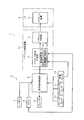
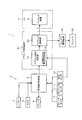
- FIG. 1 is a block diagram schematically showing an electrical configuration of a main part of an in-vehicle system including a door lock control device according to a first embodiment.
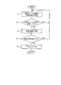
- FIG. 2 is a flowchart schematically showing a control procedure of the door lock mechanism executed by the door lock control device according to the first embodiment.
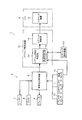
- FIG. 3 is a block diagram schematically showing an electrical configuration of a main part of an in-vehicle system including a door lock control device according to a second embodiment;
- FIG. 4 is a flowchart schematically showing a control procedure of the door lock mechanism executed by the door lock control device according to the second embodiment.
- FIG. 1 is a block diagram schematically showing an electrical configuration of a main part of an in-vehicle system including a door lock control device according to a first embodiment.
- FIG. 3 is a block diagram schematically showing an electrical configuration of a main part of an in-vehicle system including a door lock control device according to a second embodiment;
- FIG. 4 is a
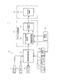
- FIG. 5 is a block diagram schematically showing an electrical configuration of a main part of an in-vehicle system including a door lock control device according to a third embodiment
- FIG. 6 is a flowchart schematically showing a control procedure of the door lock mechanism executed by the door lock control device according to the third embodiment
- FIG. 7 is a block diagram schematically showing an electrical configuration of a main part of an in-vehicle system including a door lock control device according to a fourth embodiment
- FIG. 8 is a flowchart schematically showing a control procedure of the door lock mechanism executed by the door lock control device according to the fourth embodiment.
- FIG. 9 is a block diagram schematically showing an electrical configuration of a main part of the in-vehicle system including the door lock control device according to the fifth embodiment.
- FIG. 10 is a block diagram schematically showing an electrical configuration of a main part of the in-vehicle system including the door lock control device according to the sixth embodiment.
- FIG. 11 is a block diagram schematically showing the electrical configuration of the main part of the in-vehicle system including the door lock control device according to the seventh embodiment.
- FIG. 12 is a block diagram schematically showing an electrical configuration of a main part of the in-vehicle system including the door lock control device according to the eighth embodiment.
- FIG. 1 schematically shows an electrical configuration of a main part of an in-vehicle system 1 including a door lock control device according to this embodiment mounted on a vehicle (automobile).
- the in-vehicle system 1 includes an automatic brake device 2, a door lock control device 3, and a door lock mechanism 5 provided in a door 4 portion of the vehicle.
- the automatic brake device 2 automatically activates the brake 9 by determining the possibility of a vehicle collision, and includes a collision mitigation control unit 6 including a computer.
- a radar 7 and a camera 8 connected to the collision mitigation control unit 6 are provided.
- the radar 7 outputs radio waves or ultrasonic waves from a vehicle in a specific direction, and measures the presence / absence of the reflected wave, the magnitude of the signal, time, and the like.
- the radar 7 inputs the measurement data to the collision mitigation control unit 6, and the collision mitigation control unit 6 analyzes the measurement data and recognizes the presence / absence, distance, size, and the like of an object around the vehicle.
- the camera 8 captures the situation around the vehicle and inputs the captured data to the collision mitigation control unit 6.
- the collision mitigation control unit 6 recognizes the presence and distance of obstacles such as other vehicles, people, and falling objects around the vehicle by analyzing the captured data. Further, the collision mitigation control unit 6 can use the measurement data of the laser 7 and the photographing data of the camera 8 so as to complement each other, so that the situation around the vehicle can be grasped more accurately. Further, the collision mitigation control unit 6 receives signals from the brake sensor 10, the steering sensor 11, and the vehicle speed sensor 12. The collision mitigation control unit 6 can predict the moving direction and moving distance of the host vehicle, the speed at that time, and the like from these input signals.
- the collision mitigation control unit 6 determines the collision of the own vehicle from the predicted result of the moving direction, moving distance, and speed of the own vehicle and the walking and distance of surrounding objects obtained from the laser 7 and the camera 8. Determine the possibility of When it is determined that there is a possibility of a collision, the collision relaxation control unit 6 automatically activates the brake 9 without depending on the driver's operation of the brake pedal. Thereby, the own vehicle is stopped or decelerated by the automatic brake device 2, and a collision accident is avoided or damage is reduced.
- the door 4 opens and closes an entrance for a vehicle occupant to enter and exit, and includes a door lock mechanism 5 therein.
- the door lock mechanism 5 is for locking the door 4 in a closed state that cannot be opened and closed from the outside.
- the door 4 can be operated from the outside even if the knob of the door 4 is operated. 4 cannot be opened.
- the door lock mechanism 5 is unlocked, the door 4 can be opened by operating the knob from the outside.
- a door switch is provided in the vehicle, and the door lock mechanism 5 can be locked and unlocked by a switch operation by a passenger.
- the door lock control device 3 controls the lock / unlock of the door lock mechanism 5 and includes a computer.
- the door lock control device 3 includes a door lock control determination unit 13 and a door lock control unit 14.
- the door lock control determination unit 13 receives operation information indicating whether or not the automatic brake device 2 has been operated from the collision relaxation control unit 6.
- vehicle speed information from the vehicle speed sensor 12 is input to the door lock control determination unit 13. Therefore, the door lock control determination unit 13 has functions as an acquisition unit and a vehicle speed information acquisition unit.
- the door lock control determination unit 13 determines the door lock mechanism 5 based on the brake operation information from the collision mitigation control unit 6 and the vehicle speed information from the vehicle speed sensor 12. It is determined whether to forcibly lock (and whether to unlock). Basically, the door lock control determination unit 13 determines that the door lock mechanism 5 is forcibly locked when the information indicating that the automatic brake device 2 is operated is acquired from the collision mitigation control unit 6. When it is determined that the door lock control determination unit 13 is forcibly locked, the door lock control determination unit 13 gives a forced lock signal to the door lock control unit 14.
- the door lock control determination unit 13 determines that the vehicle speed acquired from the vehicle speed sensor 12 is a predetermined speed (for example, a low speed such as 0 km / h, 10 km / h, etc.).
- a compulsory lock signal is given to the door lock control unit 14 on condition that the following is true.
- the door lock control determination unit 13 includes a vehicle speed determination value storage unit 15, and a predetermined speed (vehicle speed determination value) used for vehicle speed determination is set in advance by a user, for example, and stored in the vehicle speed determination value storage unit 15. Yes.
- the door lock control unit 14 controls the door lock mechanism 5 to be forcibly locked based on the input of a forced lock signal from the door lock control determination unit 13. Accordingly, the door lock control determination unit 13 and the door lock control unit 14 function as a control unit.
- step S1 the operation information of the automatic brake device 2 from the collision mitigation control unit 6 is acquired.
- step S2 it is determined whether or not the automatic brake device 2 is activated. If automatic brake device 2 is not operating (No in step S2), the process returns to step S1 and the process is repeated.
- the brake 9 is automatically operated.
- the door lock control determination unit 13 is notified that the automatic brake device 2 has been operated.
- vehicle speed information of the host vehicle is acquired from the vehicle speed sensor 12 in the next step S3.
- step S4 it is determined whether or not the acquired vehicle speed is equal to or lower than a predetermined speed (for example, 0 km / h or 10 km / h) preset and stored in the vehicle speed determination value storage unit 15 as a vehicle speed determination value.
- Step S4 If the vehicle speed of the host vehicle is equal to or lower than the predetermined speed (Yes in Step S4), the door lock mechanism 5 is forcibly locked by the door lock control unit 14 in Step S5. On the other hand, if the vehicle speed of the host vehicle still exceeds the predetermined speed (No in step S4), the process returns to step S1 and the process is repeated. The lock mechanism 5 is forcibly locked. Thus, when the automatic brake device 2 is activated, the door lock mechanism 5 is forcibly locked on condition that the vehicle speed of the host vehicle is equal to or lower than a predetermined speed.
- the automatic brake device 2 since the automatic brake device 2 is provided in the vehicle, when there is a possibility of a collision, the brake 9 is automatically operated to avoid a collision accident or reduce damage.
- the function of the automatic brake will be misused for the crime. That is, a bandit that attacks the vehicle intentionally jumps out ahead of the vehicle, and the vehicle is forcibly stopped by the function of the automatic brake device 2. Then, it is conceivable to open the door 4 of the vehicle to harm the occupant or to snatch money.
- the door lock control device 3 forcibly locks the door lock mechanism 5 and locks the door 4 in a closed state that cannot be opened and closed from the outside. It becomes like this. Therefore, if a bandit tries to exploit the automatic brake device 2 to attack the vehicle, when the automatic brake device 2 is activated, the door 4 of the vehicle is locked and cannot be opened from the outside. It is in a state. As a result, crimes can be prevented and passengers can be protected from robbery crimes.
- the door lock mechanism 5 is forcibly locked. Therefore, the automatic brake device 2 is abused to forcibly stop the vehicle. Such an excellent prevention effect against crimes can be obtained.
- the door lock mechanism 5 is not forcibly locked when the vehicle is traveling at a relatively high speed exceeding a predetermined speed. .
- the door lock mechanism 5 is forcibly locked for the first time when the vehicle speed drops below a predetermined speed. In this case, if the collision can be avoided without stopping the vehicle (or the vehicle speed is reduced below the predetermined speed), the door lock mechanism 5 is operated unnecessarily by accelerating as it is and continuing to travel. This can be prevented.
- the operation of the door lock mechanism 5 can be started when the vehicle becomes a predetermined low speed (for example, 10 km / h). Thereby, even when the door lock mechanism 5 takes a certain time to operate, the door 4 can be reliably locked in the closed state when the vehicle is stopped (vehicle speed is 0 km / h).
- the door lock mechanism 5 is forcibly locked on condition that the vehicle speed of the vehicle decreases to a predetermined speed or less when the automatic brake device 2 is operated.
- the door lock mechanism 5 may be forcibly locked whenever the automatic brake device 2 operates without providing such a vehicle speed condition. As a result, it is possible to obtain an excellent preventive effect against crimes such as misuse of the automatic brake device 2 to force the vehicle to stop.
- the door lock control determination unit 22 as a control unit counts time.
- a timer 23 is provided.
- the door lock control device 21 is configured to unlock the door lock mechanism 5 after a predetermined time (for example, 1 minute) has elapsed after forcibly locking the door lock mechanism 5.
- FIG. 4 shows a control procedure of the door lock mechanism 5 executed by the door lock control device 21 (the door lock control determination unit 22 and the door lock control unit 14) in the second embodiment.
- the difference from the first embodiment is that the door lock mechanism 5 is forcibly locked in step S5, but the steps S11 to S13 are added thereafter.
- step S5 After the door lock mechanism 5 is forcibly locked in step S5, the time counting operation of the timer 23 is started in the next step S11.
- step S12 it is determined whether or not a certain time (for example, 1 minute) has elapsed. If the certain time has elapsed (Yes in step S12), the door lock mechanism 5 unlocks the door 4 in step S13. Is done.
- a certain time for example, 1 minute
- a collision may be unavoidable and an accident may occur.
- a collision accident occurs, there is a possibility that the occupant himself is unable to unlock the door 4 and is trapped in the vehicle because the consciousness of the occupant is lost. In such a case, if the door 4 remains locked, it may cause a problem such as taking time to rescue from the outside.
- the door 4 when there is no vehicle collision or when the driver is not so conscious that there is a collision, the door 4 is locked by the door lock mechanism 5 for a certain period of time. Has been. Therefore, while the vehicle is safe, an operation for avoiding damage such as running the vehicle and escaping from the bandits can be performed.
- the door 4 is unlocked by the lock mechanism 5 after a certain period of time, so the door 4 is opened from the outside to rescue the injured person. Can be performed without hindrance.
- the second embodiment as in the first embodiment, it is possible to obtain an excellent prevention effect against crimes such as the automatic brake device 2 being abused to forcibly stop the vehicle.
- the vehicle occupant himself / herself cannot unlock the door 4, so that the trouble of being locked in the vehicle and delaying rescue can be solved. is there.
- FIGS. 5 and 6 illustrate a third embodiment of the present disclosure.
- the door lock control device 31 includes an acquisition unit, a door lock control determination unit 32 that functions as a control unit, and a door lock control unit 14.
- the vehicle is provided with a GPS sensor 33 as a vehicle position detection unit for detecting the position of the vehicle, and position information detected by the GPS sensor 33 is input to the door lock control determination unit 32.
- the door lock control determination unit 32 is provided with a MAP data storage unit 34.
- the MAP data storage unit 34 stores data of a caution area as a specific position.
- the attention required area means, for example, an area where crimes frequently occur, and an area with very few crimes is out of the attention required area.
- the door lock control determination unit 32 determines whether or not the host vehicle is present in the caution area stored in the MAP data storage unit 34 based on the position information from the GPS sensor 33. To do. And the operation
- the flowchart of FIG. 6 shows the control procedure of the door lock mechanism 5 executed by the door lock control device 31 in the third embodiment.
- the difference from the first embodiment is as follows. is there. That is, first, in step S21, the position information detected by the GPS sensor 33 is acquired. In the next step S ⁇ b> 22, it is determined whether or not the host vehicle is in the caution area stored in the MAP data storage unit 34. If the host vehicle is not in the caution area (outside the caution area) (No in step S22), the process returns to step S21 and the process is repeated.
- steps S1 to S5 are performed.
- the process is executed. Thereby, only when the host vehicle is in the area requiring attention, control for forcibly locking the door lock mechanism 5 is executed, and the effect of preventing crimes such as the automatic brake device 2 being abused to forcibly stop the vehicle and attack. It will be excellent. In other areas, that is, areas where there is less risk of crime, the door lock mechanism 5 is not forcibly locked even if the automatic brake device 2 is operated. Confinement can be prevented.
- the caution area where crime frequently occurs is stored in the MAP data storage unit 34 as a specific position.
- the likelihood of the crime is classified according to the road type. May be. In this case, on the highway, it is difficult for ordinary people to enter on foot, so it is very unlikely that bandits will attack the vehicle. Therefore, the road type on which the host vehicle is traveling can be used as a condition as the specific position.
- the control for forcibly locking the door lock mechanism 5 is not performed on an expressway, and the control for forcibly locking the door lock mechanism 5 when the automatic brake device 2 is operated is performed on a general road. Can do.
- the door lock control device 41 includes an acquisition unit, a door lock control determination unit 42 that functions as a control unit, and a door lock control unit 14. At this time, captured image data in the vicinity of the vehicle captured by the camera 8 is input to the door lock control determination unit 42.
- the door lock control determination unit 42 includes an image recognition / determination unit 43.
- the image recognition / determination unit 43 determines whether the person is a suspicious person using a well-known technique when there is a person approaching the vehicle. .
- the suspicious person's judgment is, for example, whether the person in the image possesses a weapon such as a stick, a gun, a knife, etc., hides his face unnaturally with a mask or a balaclava, or wears or behaves. This is based on detecting whether there are any suspicious points. Accordingly, the camera 8 and the image recognition / determination unit 43 function as a suspicious person determination unit.
- the door lock control device 41 is based on the condition that the suspicious person approaches by the image recognition / determination unit 43 when the automatic brake device 2 is operated. Is forcibly locked.
- the suspicious person is judged in the next step S31. Done.
- the next step S32 it is determined whether the risk is high (suspicious person is approaching).
- step S32 If it is determined that the risk is high (a suspicious person is approaching) (Yes in step S32), the door lock mechanism 5 is forcibly locked in step S5. On the other hand, when it is determined that the risk is low (no suspicious person) (No in step S32), the process returns to step S1 and the process is repeated. Thereby, when a suspicious person is not judged, that is, when there is no fear of a crime, even if the automatic brake device 2 operates, the door 4 is not forcibly locked.
- the automatic brake device 2 when the automatic brake device 2 is operated, it is configured to forcibly lock on the condition that it is determined that a suspicious person is approaching. Thereby, it becomes excellent in the prevention effect with respect to the crime which abuses the automatic brake device 2 and forcibly stops the vehicle and attacks. Further, when there is no fear of crime, the door lock mechanism 5 is not forcibly locked, so that it is possible to prevent occupants from being trapped when a collision accident occurs.
- FIG. 9 shows a fifth embodiment of the present disclosure.
- a drive signal is input from the airbag drive device 53 to the door lock control determination unit 52 of the door lock control device 51 when an airbag (not shown) operates.
- the door lock control determination unit 52 functions as an airbag information acquisition unit.
- the airbag driving device 53 protects the occupant by operating the airbag when a vehicle collision is detected.
- the door lock control unit 14 causes the automatic lock device 2 to operate.
- the door lock mechanism 5 is unlocked.
- the operation of the airbag can be presumed that the vehicle has collided with a considerable impact, and it is sufficiently predicted that the consciousness of the passenger will be lost. In such a case, it is better to place emphasis on occupant rescue rather than crime, and the door lock mechanism 5 is unlocked to prevent occupant confinement and rescue by opening the door from the outside. Is possible.
- FIG. 10 shows a sixth embodiment of the present disclosure.
- the door lock control device 61 according to the sixth embodiment is configured such that an operation signal from the changeover switch 63 is input to the door lock control determination unit 62.
- the change-over switch 63 is used to switch the validity / invalidity of the forced lock function of the door lock mechanism 5 and is provided so that it can be operated by a user (occupant).
- the door lock control determination unit 62 functions as a switching unit that switches validity / invalidity of the forced lock function of the door lock mechanism 5 based on the operation signal of the changeover switch 63.
- the user may operate the changeover switch 63 to enable the forced lock function of the door lock mechanism 5.
- the forced lock function of the door lock mechanism 5 may be disabled. That is, it is possible to freely switch the validity / invalidity of the forced lock function of the door lock mechanism 5 at the user's discretion, and the convenience can be improved.
- FIG. 11 shows a seventh embodiment of the present disclosure.
- the door lock control device 71 of the seventh embodiment is configured such that a driver determination signal from the driver determination unit 73 is input to the door lock control determination unit 72.
- the driver discriminating unit 73 is for discriminating (specifying) attributes such as sex and age of the driver sitting in the driver's seat of the vehicle, and detects vulnerable persons who are easily attacked by bandits such as women and elderly people. It is to be determined.
- the attribute of the driver can be determined by image recognition of a captured image of a camera that captures the inside of the vehicle (driver).
- the communication device such as Bluetooth (registered trademark) can be used to communicate with a mobile terminal such as a smartphone possessed by the driver to obtain driver attribute information. An individual driver may be specified.
- the door lock control determination unit 72 functions as a switching unit that switches between valid / invalid of the forced lock function of the door lock mechanism 5 based on the determination signal from the driver determination unit 73.
- the driver is a weak person such as a woman or an elderly person
- the function of the forced lock of the door lock mechanism 5 is made effective, and for other drivers who are less likely to get involved in crime, the door lock
- the forced lock function of the mechanism 5 can be disabled.
- the validity / invalidity of the forced lock function can be automatically switched as necessary, which is effective.
- FIG. 12 shows an eighth embodiment of the present disclosure.
- the vehicle is provided with a window opening / closing mechanism 84 that electrically opens and closes the window 83.
- the door lock control unit 82 of the door lock control device 81 outputs a closing command signal for the window 83 to the window opening / closing mechanism 84 when the door lock mechanism 5 is forcibly locked with the operation of the automatic brake device 2.
- the window opening / closing mechanism 84 closes the window 83 based on the signal.
- the window 84 is open, the risk of being attacked by bandits by abuse of the automatic brake device 2 is increased as described above.
- the window 83 is closed at the same time, so that the crime prevention effect can be further enhanced. it can.
- the automatic brake device 2 has a configuration including the radar 7 and the camera 8, but various types of automatic brake devices can be employed. Even when the vehicle backs (reverses), the automatic brake device can be configured to operate, and the present disclosure can be applied.
- the vehicle speed determination value and specific numerical values for the predetermined time are only examples, and can be changed as appropriate.
Landscapes
- Engineering & Computer Science (AREA)
- Mechanical Engineering (AREA)
- Lock And Its Accessories (AREA)
- Regulating Braking Force (AREA)
Abstract
車両のドアロック制御装置(3)は、衝突の可能性を判断して自動でブレーキを作動させる自動ブレーキ装置(2)を備えた車両に設けられ、ドアを外側から開閉不能な閉塞状態にロックするドアロック機構(5)のロック・ロック解除を制御するものであって、前記自動ブレーキ装置(2)におけるブレーキの作動情報を取得する取得部(13)と、前記取得部(13)により前記自動ブレーキ装置(2)のブレーキ作動情報を取得したときに、前記ドアロック機構(5)を強制的にロックさせる制御部(13,14)とを備えている。
Description
本出願は、2015年9月25日に出願された日本出願番号2015-188162号に基づくもので、ここにその記載内容を援用する。
本開示は、自動ブレーキ装置を備えた車両に設けられ、ドアを外側から開閉不能な閉塞状態にロックするドアロック機構のロック・ロック解除を制御する車両のドアロック制御装置に関する。
近年、車両(自動車)においては、前方の障害物との衝突防止或いは衝突時の被害軽減のために、自動ブレーキ装置を備えたものが普及してきている(例えば特許文献1参照)。この自動ブレーキ装置は、車両の進行方向を、カメラやレーダで監視し、自車両が、他の車両、人、障害物等と衝突する可能性を判断し、衝突の虞があると判断された場合に、自動でブレーキを作動させるように構成されている。これにより、運転者のブレーキ操作が遅れたような場合でも、車両を停止または減速させることができ、衝突事故の回避或いは被害の軽減が図られる。
しかしながら、上記のような車両の自動ブレーキの機能を逆手にとって、犯罪に悪用されるようなケースが考えられる。この犯罪の手口は、次のようなものとなる。即ち、車両を襲おうとする賊が、故意にその車両の前方に飛び出し、自動ブレーキ装置を作動させて車両を強制的に停止させる。そして、車両のドアを開けて乗員に危害を加えたり、金品を強奪したりするというものである。
尚、例えば特許文献1では、衝突時の乗員の閉じ込めを防止するために、自動ブレーキ装置によって車両が強制停止した場合に、ドアロック機構のロックを自動で解除することが開示されている。ところが、この構成では、停止した車両のドアが外側から容易に開くことになるので、むしろ上記のような犯罪が起きやすいものとなってしまう。
本開示は、自動ブレーキ装置を悪用して車両を強制停止させて襲うといった犯罪に対する、防止効果に優れる車両のドアロック制御装置を提供することを目的とする。
本開示の第一の態様において、車両のドアロック制御装置は、衝突の可能性を判断して自動でブレーキを作動させる自動ブレーキ装置を備えた車両に設けられ、ドアを外側から開閉不能な閉塞状態にロックするドアロック機構のロック・ロック解除を制御するものであって、前記自動ブレーキ装置におけるブレーキの作動情報を取得する取得部と、前記取得部により前記自動ブレーキ装置のブレーキ作動情報を取得したときに、前記ドアロック機構を強制的にロックさせる制御部とを備えている。
車両に自動ブレーキ装置が設けられていることにより、衝突の虞がある場合に、自動でブレーキが作動され、衝突事故の回避或いは被害の軽減が図られる。上記構成によれば、上記のように自動ブレーキ装置が作動した場合には、取得部によってブレーキの作動情報が取得され、制御部により、ドアロック機構が、ドアを外側から開閉不能な閉塞状態に強制的にロックされる。
従って、もし、賊が、自動ブレーキ装置を悪用して車両を襲おうとしても、自動ブレーキ装置が作動した場合には、車両のドアがロックされていて、外側からは開けることができない状態となっている。これにより、犯罪が未然に防止され、乗員を強盗犯罪等から守ることができる。この結果、第一の態様によれば、自動ブレーキ装置を悪用して車両を強制停止させて襲うといった犯罪に対する優れた防止効果を得ることができる。
本開示についての上記目的およびその他の目的、特徴や利点は、添付の図面を参照しながら下記の詳細な記述により、より明確になる。その図面は、
図1は、第1の実施形態に係るドアロック制御装置を含む車載システムの要部の電気的構成を概略的に示すブロック図、
図2は、第1の実施形態に係るドアロック制御装置が実行するドアロック機構の制御の手順を概略的に示すフローチャートであり、
図3は、第2の実施形態に係るドアロック制御装置を含む車載システムの要部の電気的構成を概略的に示すブロック図、
図4は、第2の実施形態に係るドアロック制御装置が実行するドアロック機構の制御の手順を概略的に示すフローチャートであり、
図5は、第3の実施形態に係るドアロック制御装置を含む車載システムの要部の電気的構成を概略的に示すブロック図、
図6は、第3の実施形態に係るドアロック制御装置が実行するドアロック機構の制御の手順を概略的に示すフローチャートであり、
図7は、第4の実施形態に係るドアロック制御装置を含む車載システムの要部の電気的構成を概略的に示すブロック図、
図8は、第4の実施形態に係るドアロック制御装置が実行するドアロック機構の制御の手順を概略的に示すフローチャートであり、
図9は、第5の実施形態に係るドアロック制御装置を含む車載システムの要部の電気的構成を概略的に示すブロック図であり、
図10は、第6の実施形態に係るドアロック制御装置を含む車載システムの要部の電気的構成を概略的に示すブロック図であり、
図11は、第7の実施形態に係るドアロック制御装置を含む車載システムの要部の電気的構成を概略的に示すブロック図であり、
図12は、第8の実施形態に係るドアロック制御装置を含む車載システムの要部の電気的構成を概略的に示すブロック図である。
(1)第1の実施形態
以下、本開示を具体化した第1の実施形態について、図1及び図2を参照しながら説明する。図1は、車両(自動車)に搭載された本実施形態に係るドアロック制御装置を含む車載システム1の要部の電気的構成を概略的に示している。本実施形態においては、車載システム1は、自動ブレーキ装置2、ドアロック制御装置3、車両のドア4部分に設けられたドアロック機構5を含んで構成される。
以下、本開示を具体化した第1の実施形態について、図1及び図2を参照しながら説明する。図1は、車両(自動車)に搭載された本実施形態に係るドアロック制御装置を含む車載システム1の要部の電気的構成を概略的に示している。本実施形態においては、車載システム1は、自動ブレーキ装置2、ドアロック制御装置3、車両のドア4部分に設けられたドアロック機構5を含んで構成される。
そのうち自動ブレーキ装置2は、車両の衝突の可能性を判断して自動でブレーキ9を作動させるもので、コンピュータを含んで構成される衝突緩和制御部6を備える。これと共に、その衝突緩和制御部6に接続されたレーダ7及びカメラ8を備えている。前記レーダ7は、車両から電波或いは超音波などを特定の方向に出力し、その反射波の有無、信号の大きさ、時間等を測定する。レーダ7は、その測定データを衝突緩和制御部6に入力し、衝突緩和制御部6は、その測定データを解析して車両周囲の物体の有無、距離、大きさ等を認識する。
前記カメラ8は、車両周囲の状況を撮影し、その撮影データを衝突緩和制御部6に入力する。衝突緩和制御部6は、その撮影データを解析することにより、車両周囲の他車両、人、落下物などの障害物の有無や距離を認識する。また、衝突緩和制御部6は、レーザ7の測定データ及びカメラ8の撮影データを相互に補完するように利用し、車両の周囲の状況をより正確に把握することができる。更に、衝突緩和制御部6には、ブレーキセンサ10、ステアリングセンサ11、車速センサ12からの信号が入力される。衝突緩和制御部6は、それら入力信号から、自車両の移動方向や移動距離、その時点での速度などを予測できる。
これにより、衝突緩和制御部6は、上記自車両の移動方向や移動距離、速度の予測結果と、前記レーザ7及びカメラ8から得られた周囲の物体の歩行や距離などから、自車両の衝突の可能性を判断する。そして、衝突緩和制御部6は、衝突の虞があると判断された場合には、ブレーキ9を、運転者のブレーキペダルの操作によることなく、自動で作動させる。これにて、自動ブレーキ装置2によって自車両が停止又は減速され、衝突事故の回避或いは被害の軽減が図られる。
前記ドア4は、車両の乗員が出入りするための出入口を開閉するものであり、内部にドアロック機構5を備えている。ドアロック機構5は、周知のように、ドア4を外側から開閉不能な閉塞状態にロックするためのものであり、ドア4がロックされると、外側からドア4のノブを操作してもドア4を開放することができなくなる。ドアロック機構5のロック解除がなされると、外側からノブを操作してドア4を開けることができる。図示はしないが、車内にはドアスイッチが設けられており、乗員によるスイッチ操作により、ドアロック機構5のロック・ロック解除を行うことができる。
さて、本実施形態に係るドアロック制御装置3は、前記ドアロック機構5のロック・ロック解除を制御するものであり、コンピュータを含んで構成されている。このドアロック制御装置3は、ドアロック制御判定部13と、ドアロック制御部14とを備えている。ドアロック制御判定部13には、前記衝突緩和制御部6から、自動ブレーキ装置2が作動したかどうかの作動情報が入力される。また、本実施形態では、ドアロック制御判定部13には、前記車速センサ12からの車速情報が入力される。従って、ドアロック制御判定部13が、取得部及び車速情報取得部としての機能を備える。
そして、次の作用説明(フローチャート説明)でも述べるように、ドアロック制御判定部13は、衝突緩和制御部6からのブレーキ作動情報及び車速センサ12からの車速情報に基づいて、ドアロック機構5の強制的にロックさせるかどうか(またロック解除させるかどうか)の判定を行う。基本的には、ドアロック制御判定部13は、衝突緩和制御部6から自動ブレーキ装置2が作動した旨の情報を取得した場合に、ドアロック機構5の強制的にロックさせると判定する。ドアロック制御判定部13は、強制的にロックさせると判定した場合には、前記ドアロック制御部14に対し、強制ロックの信号を与える。
このとき、本実施形態では、自動ブレーキ装置2が作動した場合に、ドアロック制御判定部13は、車速センサ12から取得した車速が所定速度(例えば、0km/h、10km/h等の低速)以下であることを条件に、ドアロック制御部14に対し、強制ロックの信号を与える。ドアロック制御判定部13は車速判定値記憶部15を備え、車速判定に用いる所定速度(車速判定値)が、例えば予めユーザにより設定されて車速判定値記憶部15に記憶されるようになっている。ドアロック制御部14は、ドアロック制御判定部13から強制ロックの信号が入力されることに基づいて、ドアロック機構5を強制的にロックさせるように制御する。従って、これらドアロック制御判定部13及びドアロック制御部14が、制御部として機能する。
次に、上記構成の作用について、図2も参照して述べる。図2のフローチャートは、ドアロック制御装置3(ドアロック制御判定部13及びドアロック制御部14)が実行するドアロック機構5の制御の手順を示している。即ち、まず、ステップS1では、衝突緩和制御部6からの自動ブレーキ装置2の作動情報が取得される。ステップS2では、自動ブレーキ装置2が作動したかどうかが判断される。自動ブレーキ装置2が作動していない場合には(ステップS2にてNo)、ステップS1に戻って処理が繰返される。
上記したように、自動ブレーキ装置2においては、衝突緩和制御部6により自車両の衝突の可能性が判断され、衝突の虞があると判断した場合には、ブレーキ9を自動で作動させる。このように自動ブレーキ装置2が作動したときに、ドアロック制御判定部13に自動ブレーキ装置2が作動したことが通知される。自動ブレーキ装置2が作動した場合には(ステップS2にてYes)、次のステップS3にて、車速センサ12からの自車両の車速情報が取得される。ステップS4では、取得された車速が、車速判定値として予め車速判定値記憶部15に設定、記憶された所定速度(例えば、0km/h或いは10km/h)以下かどうかが判断される。
そして、自車両の車速が所定速度以下である場合には(ステップS4にてYes)、ステップS5にて、ドアロック制御部14によりドアロック機構5が強制的にロックされるようになる。一方、自車両の車速が未だ所定速度を超えている場合には(ステップS4にてNo)、ステップS1に戻って処理が繰返され、自車両の車速が所定速度以下になった時点で、ドアロック機構5が強制的にロックされる。これにて、自動ブレーキ装置2が作動した場合には、自車両の車速が所定速度以下になったことを条件に、ドアロック機構5が強制的にロックされるのである。
ここで、車両に自動ブレーキ装置2が設けられていることにより、衝突の虞がある場合に、自動でブレーキ9が動作され、衝突事故の回避或いは被害の軽減が図られる。しかし、自動ブレーキの機能を逆手にとって、犯罪に悪用されることが考えられる。即ち、車両を襲おうとする賊が、故意にその車両の前方に飛び出し、自動ブレーキ装置2の機能により車両を強制的に停止させる。そして、車両のドア4を開けて乗員に危害を加えたり、金品を強奪したりすることが考えられる。
ところが、本実施形態では、自動ブレーキ装置2が作動した場合には、ドアロック制御装置3により、ドアロック機構5が強制的にロックされ、ドア4が外側から開閉不能な閉塞状態にロックされるようになる。従って、もし、賊が、自動ブレーキ装置2を悪用して車両を襲おうとしても、自動ブレーキ装置2が作動した場合には、車両のドア4がロックされていて、外側からは開けることができない状態となっている。これにより、犯罪が未然に防止され、乗員を強盗犯罪等から守ることができるのである。
このように本実施形態によれば、自動ブレーキ装置2が作動したときに、ドアロック機構5を強制的にロックさせる構成としたので、自動ブレーキ装置2を悪用して車両を強制停止させて襲うといった犯罪に対する優れた防止効果を得ることができる。
特に本実施形態では、自動ブレーキ装置2が作動した場合でも、車両が所定速度を超えている比較的高速で走行している場合には、ドアロック機構5が強制的にロックされることがない。そして、車両の速度が所定速度以下に低下した時点で、初めてドアロック機構5が強制的にロックされるように構成した。この場合、車両が停止する(或いは車速が所定速度以下に低下する)ことなく、衝突が回避できた場合には、そのまま加速して走行を続けることにより、無駄にドアロック機構5が動作されることを防止することができる。一方、車両が所定の低速になった時点(例えば10km/h)でドアロック機構5の動作を開始させることができる。これにより、ドアロック機構5の動作に一定の時間がかかる場合であっても、車両の停止時(車速が0km/h)には確実にドア4を閉塞状態にロックしておくことができる。
尚、上記第1の実施形態では、自動ブレーキ装置2が作動したときに、車両の車速が所定速度以下に低下することを条件に、ドアロック機構5を強制的にロックさせるように構成した。ところが、そのような車速の条件を設けることなく、自動ブレーキ装置2が作動した場合に常にドアロック機構5を強制的にロックさせる構成としても良い。これにより、やはり、自動ブレーキ装置2を悪用して車両を強制停止させて襲うといった犯罪に対する、優れた防止効果を得ることができる。
(2)第2の実施形態
次に、図3及び図4を参照して、本開示の第2の実施形態について説明する。尚、以下に述べる第2の実施形態、更にはそれ以降の各実施形態においても、自動ブレーキ装置2の構成などは上記第1の実施形態と共通する。従って、上記第1の実施形態と共通する部分には、同一の符号を付して新たな説明を省略し、以下、上記第1の実施形態と異なる点を中心に述べることとする。
次に、図3及び図4を参照して、本開示の第2の実施形態について説明する。尚、以下に述べる第2の実施形態、更にはそれ以降の各実施形態においても、自動ブレーキ装置2の構成などは上記第1の実施形態と共通する。従って、上記第1の実施形態と共通する部分には、同一の符号を付して新たな説明を省略し、以下、上記第1の実施形態と異なる点を中心に述べることとする。
図3に示すように、この第2の実施形態のドアロック制御装置21では、上記第1の実施形態と同等の構成に加えて、制御部としてのドアロック制御判定部22は、時間をカウントするためのタイマ23を備えている。そして、ドアロック制御装置21は、ドアロック機構5を強制的にロックさせた後、一定時間(例えば1分)経過後に、ドアロック機構5のロック解除を行うように構成されている。
図4のフローチャートは、この第2の実施形態における、ドアロック制御装置21(ドアロック制御判定部22及びドアロック制御部14)が実行するドアロック機構5の制御の手順を示している。上記第1の実施形態と異なる点は、ステップS5にて、ドアロック機構5を強制的にロックさせるのであるが、それ以降に、ステップS11~S13の処理を付加したところにある。
即ち、ステップS5にて、ドアロック機構5を強制的にロックさせた後、次のステップS11では、タイマ23の計時動作がスタートとされる。ステップS12では、一定時間(例えば1分間)が経過したかどうかが判断され、一定時間が経過したならば(ステップS12にてYes)、ステップS13にて、ドアロック機構5によるドア4のロック解除が行われる。
ここで、上記のように自動ブレーキ装置2が動作したとしても、衝突を避け得ず、事故が発生してしまうことがある。衝突事故が発生した場合、乗員の意識がなくなるなどで、乗員自身がドア4のロックを解除できずに、車内に閉じ込められる虞がある。このような場合、ドア4のロックがされたままであると、外部から救助するのに時間がかかるなどの不具合を招いてしまう。
この第2の本実施形態では、車両の衝突がなかった、或いは、衝突があっても運転者が意識を失うほどではなかった場合には、一定時間についてはドアロック機構5によりドア4がロックされている。従って、その安全な間に、車両を走行させて賊から逃げるなどの被害回避のための動作を行うことができる。一方、衝突事故が発生して運転者が意識を失ったような場合には、一定時間後にロック機構5によるドア4のロックが解除されるので、外側からドア4を開け、怪我人の救助動作を支障なく行うことができる。
従って、この第2の実施形態によれば、上記第1の実施形態と同様に、自動ブレーキ装置2を悪用して車両を強制停止させて襲うといった犯罪に対する優れた防止効果を得ることができる。そして、それに加えて、実際に衝突事故が発生したときの、車両の乗員自身がドア4のロックを解除できないケースで、車内に閉じ込められて救助が遅れてしまうといった不具合を解消することができるのである。
(3)第3の実施形態
図5及び図6は、本開示の第3の実施形態を示すものである。この第3の実施形態に係るドアロック制御装置31は、取得部、制御部として機能するドアロック制御判定部32及びドアロック制御部14を備えている。車両には、自車位置を検出するための車両位置検出部としてのGPSセンサ33が設けられており、このGPSセンサ33の検出した位置情報が、ドアロック制御判定部32に入力される。
図5及び図6は、本開示の第3の実施形態を示すものである。この第3の実施形態に係るドアロック制御装置31は、取得部、制御部として機能するドアロック制御判定部32及びドアロック制御部14を備えている。車両には、自車位置を検出するための車両位置検出部としてのGPSセンサ33が設けられており、このGPSセンサ33の検出した位置情報が、ドアロック制御判定部32に入力される。
ドアロック制御判定部32には、MAPデータ記憶部34が設けられており、このMAPデータ記憶部34には、特定の位置としての要注意エリアのデータが記憶されている。要注意エリアとは、例えば統計的に犯罪が多発する地域等をいい、犯罪のごく少ない地域は、要注意エリアから外れる。次のフローチャート説明で述べるように、ドアロック制御判定部32は、GPSセンサ33からの位置情報に基づき、MAPデータ記憶部34に記憶された要注意エリアに自車両が存在しているかどうかを判断する。そして、自車両が要注意エリアにいることを条件に、ドアロック機構5を強制的にロックさせる動作を実行する。
図6のフローチャートは、この第3の実施形態における、ドアロック制御装置31が実行するドアロック機構5の制御の手順を示しており、上記第1の実施形態と異なるところは、次の点にある。即ち、まずステップS21にて、GPSセンサ33の検出した位置情報が取得される。次のステップS22では、自車両が、MAPデータ記憶部34に記憶されている要注意エリア内にいるかどうかが判断される。自車両が要注意エリア内にいない(要注意エリア外にいる)場合には(ステップS22にてNo)、ステップS21に戻り、処理が繰返される。
一方、自車両が要注意エリア内にいると判断された場合には(ステップS22にてYes)、それ以降に、上記第1の実施形態(図2のフローチャート)と同様に、ステップS1~S5の処理が実行される。これにより、自車両が要注意エリアにいるときにのみ、ドアロック機構5を強制的にロックさせる制御が実行され、自動ブレーキ装置2を悪用して車両を強制停止させて襲うといった犯罪に対する防止効果に優れたものとなる。また、それ以外のエリア、つまり犯罪の虞の少ないエリアでは、自動ブレーキ装置2が作動されても、ドアロック機構5が強制的にロックされることはないので、衝突事故の発生時における乗員の閉じ込めを防止することができるのである。
尚、この第3の実施形態では、特定の位置として、犯罪が多発する要注意エリアをMAPデータ記憶部34に記憶させるようにしたが、道路種別で、犯罪の起こり易さを区分するようにしても良い。この場合、高速道路では、一般人が徒歩で進入することが困難なため、賊が車両を襲うといった可能性もごく低い。従って、特定の位置として、自車両が走行している道路種別を条件とすることができる。例えば、高速道路では、ドアロック機構5を強制的にロックさせる制御を行わず、一般道路では、自動ブレーキ装置2の作動時にドアロック機構5を強制的にロックさせる制御を実行する構成とすることができる。
(4)第4、第5の実施形態
次に、図7及び図8を参照して、本開示の第4の実施形態について説明する。この第4の実施形態に係るドアロック制御装置41は、取得部、制御部として機能するドアロック制御判定部42及びドアロック制御部14を備えている。このとき、ドアロック制御判定部42には、前記カメラ8が撮影した車両の近傍の撮影画像データが入力されるようになっている。これと共に、ドアロック制御判定部42は、画像認識・判断部43を備えている。
次に、図7及び図8を参照して、本開示の第4の実施形態について説明する。この第4の実施形態に係るドアロック制御装置41は、取得部、制御部として機能するドアロック制御判定部42及びドアロック制御部14を備えている。このとき、ドアロック制御判定部42には、前記カメラ8が撮影した車両の近傍の撮影画像データが入力されるようになっている。これと共に、ドアロック制御判定部42は、画像認識・判断部43を備えている。
前記画像認識・判断部43は、カメラ8の撮影画像データから、車両に接近する人物があったときに、周知の手法を用いて、当該人物が不審者かどうかを判断するようになっている。不審者の判断は、例えば、画像中の人物が、棒や、銃、刃物などの武器を所持しているか、覆面や目出し帽等により顔を不自然に隠しているか、服装や振る舞いなどに不審点はないか等を検出することに基づいて行われる。従って、カメラ8及び画像認識・判断部43が、不審者判断部として機能する。
そして、図8のフローチャートに示すように、ドアロック制御装置41は、自動ブレーキ装置2の作動時に、画像認識・判断部43により不審者の接近が判断されたことを条件に、ドアロック機構5を強制的にロックさせるように構成されている。即ち、自動ブレーキ装置2が作動し(ステップS1、S2)、車速が車速判定値以下であった場合には(ステップS4にてYes)、次のステップS31にて、画像データの不審者判断が行われる。次のステップS32にて、危険性が大きい(不審者が近付いている)かどうかが判断される。
危険性が大きい(不審者が近付いている)と判断された場合には(ステップS32にてYes)、ステップS5にて、ドアロック機構5が強制的にロックされる。一方、危険性が小さい(不審者はいない)と判断された場合には(ステップS32にてNo)、ステップS1に戻って処理が繰返される。これにより、不審者が判断されない場合、つまり犯罪の虞のない場合には、自動ブレーキ装置2が作動しても、ドア4の強制的なロックは行われない。
このように第4の実施形態によれば、自動ブレーキ装置2の作動時に、不審者の接近であることが判断されたことを条件に、強制的なロックを行う構成とした。これにより、自動ブレーキ装置2を悪用して車両を強制停止させて襲うといった犯罪に対する防止効果に優れたものとなる。また、犯罪の虞のない場合には、ドアロック機構5が強制的にロックされることはないので、衝突事故の発生時における乗員の閉じ込めを防止することができる。
図9は、本開示の第5の実施形態を示すものである。この第5の実施形態では、ドアロック制御装置51のドアロック制御判定部52には、図示しないエアバッグが動作したときに、エアバッグ駆動装置53から駆動信号が入力される。従って、ドアロック制御判定部52がエアバッグ情報取得部として機能する。周知のように、エアバッグ駆動装置53は、車両の衝突を検知したときにエアバッグを動作させて乗員を守る。
本実施形態に係るドアロック制御装置51は、エアバッグ駆動装置53からエアバッグが動作した旨の駆動信号を取得した場合には、自動ブレーキ装置2が作動したとしても、ドアロック制御部14により、ドアロック機構5のロック解除を行う。この場合、エアバッグが動作することは、かなりの衝撃で車両が衝突したと推測でき、乗員の意識がなくなることも十分に予測される。そのような場合には、犯罪よりもむしろ、乗員の救助を重視した方が良く、ドアロック機構5のロック解除がなされることにより、乗員の閉じ込めを防止し、外側からドアを開けての救助が可能となる。
(5)第6~第8の実施形態、その他の実施形態
図10は、本開示の第6の実施形態を示すものである。この第6の実施形態のドアロック制御装置61では、ドアロック制御判定部62に、切替スイッチ63からの操作信号が入力されるように構成されている。前記切替スイッチ63は、ドアロック機構5の強制ロックの機能の有効・無効を切替えるためのもので、ユーザ(乗員)による操作可能に設けられている。ドアロック制御判定部62は、切替スイッチ63の操作信号に基づいて、ドアロック機構5の強制ロックの機能の有効・無効を切替える切替部として機能する。
図10は、本開示の第6の実施形態を示すものである。この第6の実施形態のドアロック制御装置61では、ドアロック制御判定部62に、切替スイッチ63からの操作信号が入力されるように構成されている。前記切替スイッチ63は、ドアロック機構5の強制ロックの機能の有効・無効を切替えるためのもので、ユーザ(乗員)による操作可能に設けられている。ドアロック制御判定部62は、切替スイッチ63の操作信号に基づいて、ドアロック機構5の強制ロックの機能の有効・無効を切替える切替部として機能する。
ここで、上記したような犯罪から乗員を守るという観点からは、ドアロック機構5の強制ロックの機能を有効とすることが望ましい。一方、ドアロック機構5の強制ロックの機能を常に有効にしている場合には、衝突事故発生時の外部からの救助の遅れの虞があり、乗員の閉じ込め防止の観点からは、強制ロックがなされない方が好ましい事情もある。このとき、車両が走行する地域や時間帯などの客観的な条件で、犯罪に巻き込まれる可能性が変動するし、ユーザ(乗員)の身分や地位、性別や年齢、乗員の数、車両の車種などによっても、襲われる可能性が変わってくる。犯罪防止と、衝突時の閉じ込め防止とのどちらを重視するかといった、ユーザの意識の問題もある。
そこで、ユーザは、犯罪に巻き込まれる虞があると判断した場合には、切替スイッチ63を操作して、ドアロック機構5の強制ロックの機能を有効にすれば良い。一方、ユーザがそのような虞がない(衝突時の閉じ込め防止の方が重要である)と判断した場合には、ドアロック機構5の強制ロックの機能を無効にすれば良い。つまり、ユーザの判断で、ドアロック機構5の強制ロックの機能の有効・無効を自在に切替えることができ、利便性を高めることができる。
図11は、本開示の第7の実施形態を示すものである。この第7の実施形態のドアロック制御装置71では、ドアロック制御判定部72に、運転者判別部73からの運転者判別信号が入力されるように構成されている。運転者判別部73は、車両の運転席に座った運転者の、性別、年齢等の属性を判別(特定)するためのものであり、女性や高齢者などの、賊に襲われやすい弱者を判別するものである。具体的には、例えば、車内(運転者)を撮影するカメラの撮影画像の画像認識により、運転者の属性を判定することができる。Bluetooth(登録商標)等の通信装置により、運転者の所持するスマートフォン等の携帯端末と通信して運転者の属性情報を得るようすることもできる。運転者個人を特定するようにしても良い。
そして、ドアロック制御判定部72は、運転者判別部73からの判別信号に基づいて、ドアロック機構5の強制ロックの機能の有効・無効を切替える切替部として機能する。この場合、運転者が、女性や高齢者など弱者である場合には、ドアロック機構5の強制ロックの機能を有効とし、それ以外の、犯罪に巻き込まれる虞の小さい運転者に関しては、ドアロック機構5の強制ロックの機能を無効とすることができる。これにより、必要に応じて強制ロックの機能の有効・無効を自動で切替えることができ、効果的となる。
図12は、本開示の第8の実施形態を示すものである。この実施形態では、車両には、ウインドウ83を電動により開閉するウインドウ開閉機構84が設けられている。そして、ドアロック制御装置81のドアロック制御部82は、自動ブレーキ装置2の作動に伴いドアロック機構5を強制ロックする場合に、ウインドウ開閉機構84に対するウインドウ83の閉塞指令信号を出力する。ウインドウ開閉機構84は、その信号に基づきウインドウ83を閉塞する。
ここで、ウインドウ84が開いている場合も、上記したと同様に自動ブレーキ装置2を悪用して賊に襲われる危険性が大きくなる。この第8の実施形態によれば、自動ブレーキ装置2の作動に伴いドアロック機構5を強制ロックする場合に、併せてウインドウ83が閉塞されるようになるので、より一層防犯効果を高めることができる。
尚、上記各実施形態では、自動ブレーキ装置2としてレーダ7とカメラ8とを備えた構成のものを例としたが、各種構成の自動ブレーキ装置を採用することができる。車両がバック(後進)する場合も、自動ブレーキ装置を作動させる構成とすることができ、本開示を適用することができる。車速判定値や一定時間についての具体的数値についても、一例を示したに過ぎず、適宜変更が可能である。その他、上記した複数の実施形態を組合せて実施することも可能である。本開示は、実施例に準拠して記述されたが、本開示は当該実施例や構造に限定されるものではないと理解される。本開示は、様々な変形例や均等範囲内の変形をも包含する。加えて、様々な組み合わせや形態、さらには、それらに位置要素のみ、それ以上、あるいはそれ以下、を含む他の組み合わせや形態をも、本開示の範疇や思想範囲に入るものである。
Claims (9)
- 衝突の可能性を判断して自動でブレーキを作動させる自動ブレーキ装置(2)を備えた車両に設けられ、ドア(4)を外側から開閉不能な閉塞状態にロックするドアロック機構(5)のロック・ロック解除を制御するドアロック制御装置(3)であって、
前記自動ブレーキ装置(2)におけるブレーキの作動情報を取得する取得部(13)と、
前記取得部(13)により前記自動ブレーキ装置(2)のブレーキ作動情報を取得したときに、前記ドアロック機構(5)を強制的にロックさせる制御部(13、14)とを備える、車両のドアロック制御装置。 - 請求項1記載の車両のドアロック制御装置において、
前記車両の車速の情報を取得する車速情報取得部(13)を備え、
前記制御部(13、14)は、前記車速情報取得部(13)が取得した車速が所定速度以下であることを条件に、前記ドアロック機構(5)を強制的にロックさせる。 - 請求項1又は2記載の車両のドアロック制御装置において、
前記制御部(13、14)は、前記ドアロック機構(5)を強制的にロックさせた後、一定時間経過後に、ロック解除を行う。 - 請求項1から3のいずれか一項に記載の車両のドアロック制御装置において、
前記車両が特定の位置にいるかどうかを検出する車両位置検出部(33)を備え、
前記制御部(13、14)は、前記車両位置検出部(33)の検出に基づき、車両が特定の位置にいることを条件に、前記ドアロック機構(5)を強制的にロックさせる。 - 請求項1から4のいずれか一項に記載の車両のドアロック制御装置において、
前記自動ブレーキ装置(2)の作動時に、前記車両に接近する人物があったときに、当該人物が不審者かどうかを判断する不審者判断部(8、43)を備え、
前記制御部(13、14)は、前記不審者判断部(8、43)により不審者の接近が判断されたことを条件に、前記ドアロック機構(5)を強制的にロックさせる。 - 請求項1から5のいずれか一項に記載の車両のドアロック制御装置において、
前記車両に搭載されたエアバッグの動作状況を取得するエアバッグ情報取得部(52)を備え、
前記制御部(13、14)は、前記エアバッグ情報取得部(52)がエアバッグが動作した情報を取得した場合には、前記ドアロック機構(5)のロック解除を行う。 - 請求項1から6のいずれか一項に記載の車両のドアロック制御装置において、
ユーザが操作可能な切替スイッチ(63)を備えると共に、
前記切替スイッチ(63)が操作されることに基づいて、前記制御部(13、14)によるドアロック機構(5)の強制ロックの機能の有効・無効を切替える切替部(62)を備える。 - 請求項1から7のいずれか一項に記載の車両のドアロック制御装置において、
前記運転者の属性を判別する運転者判別部(73)を備えると共に、
前記運転者判別部(73)の判別に基づいて、前記制御部(13、14)によるドアロック機構(5)の強制ロックの機能の有効・無効を切替える切替部(72)を備える。 - 請求項1から8のいずれか一項に記載の車両のドアロック制御装置において、
前記車両は、ウインドウを自動で開閉するウインドウ開閉機構(84)を備え、
前記制御部(13、14)は、前記ドアロック機構(5)が強制ロックされた場合には、併せて、ウインドウ開閉機構(84)に対するウインドウの閉塞指令信号を出力する。
Applications Claiming Priority (2)
| Application Number | Priority Date | Filing Date | Title |
|---|---|---|---|
| JP2015-188162 | 2015-09-25 | ||
| JP2015188162A JP6610122B2 (ja) | 2015-09-25 | 2015-09-25 | 車両のドアロック制御装置 |
Publications (1)
| Publication Number | Publication Date |
|---|---|
| WO2017051825A1 true WO2017051825A1 (ja) | 2017-03-30 |
Family
ID=58386725
Family Applications (1)
| Application Number | Title | Priority Date | Filing Date |
|---|---|---|---|
| PCT/JP2016/077854 Ceased WO2017051825A1 (ja) | 2015-09-25 | 2016-09-21 | 車両のドアロック制御装置 |
Country Status (2)
| Country | Link |
|---|---|
| JP (1) | JP6610122B2 (ja) |
| WO (1) | WO2017051825A1 (ja) |
Cited By (2)
| Publication number | Priority date | Publication date | Assignee | Title |
|---|---|---|---|---|
| CN113879244A (zh) * | 2020-07-02 | 2022-01-04 | 宝能汽车集团有限公司 | 车辆碰撞后的车门安全解锁方法以及车载智能终端 |
| CN115217373A (zh) * | 2022-03-31 | 2022-10-21 | 广州汽车集团股份有限公司 | 预碰撞门锁控制方法、装置、车辆及存储介质 |
Families Citing this family (5)
| Publication number | Priority date | Publication date | Assignee | Title |
|---|---|---|---|---|
| CN109591745A (zh) * | 2018-12-05 | 2019-04-09 | 睿驰达新能源汽车科技(北京)有限公司 | 一种行车落锁方法和装置 |
| CN111075282B (zh) * | 2020-01-14 | 2020-10-23 | 威马汽车科技集团有限公司 | 一种自发电防车门打开紧急保护装置 |
| WO2022172400A1 (ja) * | 2021-02-12 | 2022-08-18 | 三菱電機株式会社 | 車両監視装置及び車両監視システム |
| JP7683345B2 (ja) * | 2021-06-23 | 2025-05-27 | 株式会社Jvcケンウッド | 車両用ドアロック制御装置及び車両用ドアロック制御方法 |
| CN116291067B (zh) * | 2023-04-20 | 2024-05-28 | 重庆赛力斯新能源汽车设计院有限公司 | 一种车门锁智能启闭的控制方法及装置 |
Citations (8)
| Publication number | Priority date | Publication date | Assignee | Title |
|---|---|---|---|---|
| JPH0578619U (ja) * | 1992-03-31 | 1993-10-26 | ナイルス部品株式会社 | エアバック連動ドアロック装置 |
| JP2000160932A (ja) * | 1998-12-01 | 2000-06-13 | Fuji Heavy Ind Ltd | キーレスエントリシステム |
| JP2002039762A (ja) * | 2000-07-28 | 2002-02-06 | Denso Corp | カーナビゲーションシステム |
| JP2004116244A (ja) * | 2002-09-30 | 2004-04-15 | Aisin Seiki Co Ltd | 車両用ドアロック装置 |
| JP2006214123A (ja) * | 2005-02-02 | 2006-08-17 | Fuji Heavy Ind Ltd | 車両用ドアロックシステム |
| JP2012196998A (ja) * | 2011-03-18 | 2012-10-18 | Fuji Heavy Ind Ltd | 車両の運転動作設定システム |
| JP2013136274A (ja) * | 2011-12-28 | 2013-07-11 | Suzuki Motor Corp | 車両の侵入防止装置 |
| JP2013241151A (ja) * | 2012-05-22 | 2013-12-05 | Daimler Ag | 車両用ドアロック解除装置 |
Family Cites Families (2)
| Publication number | Priority date | Publication date | Assignee | Title |
|---|---|---|---|---|
| JP3642308B2 (ja) * | 2001-10-04 | 2005-04-27 | 日産自動車株式会社 | 車両用制動制御装置 |
| JP2006007869A (ja) * | 2004-06-23 | 2006-01-12 | Toyota Motor Corp | 車両のドア状態制御装置 |
-
2015
- 2015-09-25 JP JP2015188162A patent/JP6610122B2/ja not_active Expired - Fee Related
-
2016
- 2016-09-21 WO PCT/JP2016/077854 patent/WO2017051825A1/ja not_active Ceased
Patent Citations (8)
| Publication number | Priority date | Publication date | Assignee | Title |
|---|---|---|---|---|
| JPH0578619U (ja) * | 1992-03-31 | 1993-10-26 | ナイルス部品株式会社 | エアバック連動ドアロック装置 |
| JP2000160932A (ja) * | 1998-12-01 | 2000-06-13 | Fuji Heavy Ind Ltd | キーレスエントリシステム |
| JP2002039762A (ja) * | 2000-07-28 | 2002-02-06 | Denso Corp | カーナビゲーションシステム |
| JP2004116244A (ja) * | 2002-09-30 | 2004-04-15 | Aisin Seiki Co Ltd | 車両用ドアロック装置 |
| JP2006214123A (ja) * | 2005-02-02 | 2006-08-17 | Fuji Heavy Ind Ltd | 車両用ドアロックシステム |
| JP2012196998A (ja) * | 2011-03-18 | 2012-10-18 | Fuji Heavy Ind Ltd | 車両の運転動作設定システム |
| JP2013136274A (ja) * | 2011-12-28 | 2013-07-11 | Suzuki Motor Corp | 車両の侵入防止装置 |
| JP2013241151A (ja) * | 2012-05-22 | 2013-12-05 | Daimler Ag | 車両用ドアロック解除装置 |
Cited By (3)
| Publication number | Priority date | Publication date | Assignee | Title |
|---|---|---|---|---|
| CN113879244A (zh) * | 2020-07-02 | 2022-01-04 | 宝能汽车集团有限公司 | 车辆碰撞后的车门安全解锁方法以及车载智能终端 |
| CN115217373A (zh) * | 2022-03-31 | 2022-10-21 | 广州汽车集团股份有限公司 | 预碰撞门锁控制方法、装置、车辆及存储介质 |
| CN115217373B (zh) * | 2022-03-31 | 2024-05-14 | 广州汽车集团股份有限公司 | 预碰撞门锁控制方法、装置、车辆及存储介质 |
Also Published As
| Publication number | Publication date |
|---|---|
| JP2017061816A (ja) | 2017-03-30 |
| JP6610122B2 (ja) | 2019-11-27 |
Similar Documents
| Publication | Publication Date | Title |
|---|---|---|
| JP6610122B2 (ja) | 車両のドアロック制御装置 | |
| CN104859651B (zh) | 一种提高停车开门安全性的危险探测与预防方法 | |
| US10435920B2 (en) | Safety system for preventing a vehicle door from opening into traffic | |
| EP3594035B1 (en) | A vehicle comprising a door opening warning system | |
| EP3584099B1 (en) | Vehicular periphery monitoring device | |
| KR101927217B1 (ko) | 도어락을 위한 스마트키 시스템의 제어 방법 | |
| JP2008158578A (ja) | 車両の降車安全装置及び車両の安全降車方法 | |
| JP6825300B2 (ja) | 車両用ドア装置 | |
| US11155261B2 (en) | Vehicle control device, vehicle control method, and recording medium | |
| JP6011791B2 (ja) | 車両用後方監視装置 | |
| CN105672785A (zh) | 一种车辆开门防撞系统及控制方法 | |
| WO2019008917A1 (ja) | 制御装置 | |
| JP2014019390A (ja) | 緊急退避装置 | |
| CN203237138U (zh) | 一种汽车用安全装置 | |
| JP2017019419A (ja) | 車輛用ドア開閉制御装置およびドア開閉制御システム、ドア開閉予告システム | |
| JP2017047739A (ja) | 車両制御装置 | |
| JP2007077774A (ja) | 車両用施錠装置 | |
| JP6143036B2 (ja) | 車両用後方監視装置 | |
| CN112727272A (zh) | 一种基于盲区监测的安全策略系统及方法 | |
| CN204775108U (zh) | 防入侵车辆车门锁定系统 | |
| EP2666945A1 (en) | A door stop system | |
| CN114537310A (zh) | 门控制装置 | |
| KR102297067B1 (ko) | 차량의 파워 슬라이딩 도어 제어방법 | |
| JP6351104B2 (ja) | ドアロック制御装置 | |
| JP2008290496A (ja) | 運転制御装置 |
Legal Events
| Date | Code | Title | Description |
|---|---|---|---|
| 121 | Ep: the epo has been informed by wipo that ep was designated in this application |
Ref document number: 16848613 Country of ref document: EP Kind code of ref document: A1 |
|
| NENP | Non-entry into the national phase |
Ref country code: DE |
|
| 122 | Ep: pct application non-entry in european phase |
Ref document number: 16848613 Country of ref document: EP Kind code of ref document: A1 |