WO2017051823A1 - 磁気ギア装置 - Google Patents
磁気ギア装置 Download PDFInfo
- Publication number
- WO2017051823A1 WO2017051823A1 PCT/JP2016/077841 JP2016077841W WO2017051823A1 WO 2017051823 A1 WO2017051823 A1 WO 2017051823A1 JP 2016077841 W JP2016077841 W JP 2016077841W WO 2017051823 A1 WO2017051823 A1 WO 2017051823A1
- Authority
- WO
- WIPO (PCT)
- Prior art keywords
- magnetic
- row
- rotor
- magnet
- magnet row
- Prior art date
- Legal status (The legal status is an assumption and is not a legal conclusion. Google has not performed a legal analysis and makes no representation as to the accuracy of the status listed.)
- Ceased
Links
Images




Classifications
-
- H—ELECTRICITY
- H02—GENERATION; CONVERSION OR DISTRIBUTION OF ELECTRIC POWER
- H02K—DYNAMO-ELECTRIC MACHINES
- H02K49/00—Dynamo-electric clutches; Dynamo-electric brakes
- H02K49/10—Dynamo-electric clutches; Dynamo-electric brakes of the permanent-magnet type
- H02K49/102—Magnetic gearings, i.e. assembly of gears, linear or rotary, by which motion is magnetically transferred without physical contact
-
- F—MECHANICAL ENGINEERING; LIGHTING; HEATING; WEAPONS; BLASTING
- F16—ENGINEERING ELEMENTS AND UNITS; GENERAL MEASURES FOR PRODUCING AND MAINTAINING EFFECTIVE FUNCTIONING OF MACHINES OR INSTALLATIONS; THERMAL INSULATION IN GENERAL
- F16H—GEARING
- F16H49/00—Other gearings
-
- H—ELECTRICITY
- H02—GENERATION; CONVERSION OR DISTRIBUTION OF ELECTRIC POWER
- H02K—DYNAMO-ELECTRIC MACHINES
- H02K1/00—Details of the magnetic circuit
- H02K1/06—Details of the magnetic circuit characterised by the shape, form or construction
- H02K1/22—Rotating parts of the magnetic circuit
- H02K1/27—Rotor cores with permanent magnets
- H02K1/2793—Rotors axially facing stators
- H02K1/2795—Rotors axially facing stators the rotor consisting of two or more circumferentially positioned magnets
- H02K1/2798—Rotors axially facing stators the rotor consisting of two or more circumferentially positioned magnets where both axial sides of the stator face a rotor
Definitions
- the present invention relates to a magnetic gear device having an axial gap structure and transmitting power using magnetic force.
- Patent Document 1 discloses a magnetic gear device having a radial gap structure.
- the magnetic gear device according to Patent Literature 1 is arranged on the outer peripheral side of the first internal gear having a plurality of magnet pieces on the outer peripheral portion, and on the outer peripheral portion of the first internal gear, and a plurality of magnet pieces on the inner peripheral portion and the outer peripheral portion.
- a second internal gear, and an external gear disposed on the outer peripheral side of the second internal gear and having a plurality of magnet pieces on the inner peripheral portion.
- Magnetic tooth portions are disposed between the first internal gear and the second internal gear, and magnetic tooth portions are also disposed between the second internal gear and the external gear.
- the magnetic gear device according to Patent Document 1 configured as described above achieves a high gear ratio by arranging gears and magnetic teeth in multiple stages in the radial direction.
- Patent Document 2 discloses a magnetic gear device having an axial gap structure. A plurality of magnetic pole pairs are arranged between the first and second magnet arrays, and the first and second magnet arrays, each having a plurality of magnetic pole pairs disposed along the circumferential direction. And a disc-shaped intermediate yoke on which the body is arranged.
- the magnetic gear device according to Patent Document 1 has a problem that the size is increased in the radial direction. Moreover, since the magnetic gear apparatus according to Patent Document 1 employs a radial gap structure, there is a problem in that there is a limit to downsizing in the rotation axis direction.
- the magnetic gear device according to Patent Document 2 employs a general axial gap structure, and there is a limit to miniaturization and improvement of the gear ratio.
- the present invention has been made in view of such circumstances, and an object thereof is to provide a small magnetic gear device having a high gear ratio.
- the magnetic gear device includes a disk-shaped first magnet array in which a plurality of magnetic pole pairs are respectively disposed along a circumferential direction, and a plurality of magnetic bodies are disposed along the circumferential direction.
- a disk-shaped first magnetic body row that modulates the spatial frequency of the magnetic field generated by one magnet row, a center line substantially coincides with the center line of the first magnet row, and a plurality of magnetic pole pairs along the circumferential direction
- the magnetic body row, and the first magnetic body row and the second magnetic body row are arranged between the first magnetic body row and the second magnetic body row.
- a disk-shaped coupler for magnetically coupling two magnet arrays.
- each magnet row, the magnetic body row, and the coupler have a disk shape and are arranged in the center line direction, so that the enlargement in the radial direction can be suppressed.
- the first magnet row and the first magnetic row are magnetically connected to the second magnet row and the second magnetic row by a disk-shaped coupler, a plurality of magnetic gears are simply centered. Compared to a configuration in which the lines are arranged in the line direction and connected by the rotation shaft, an increase in size in the center line direction can be suppressed.
- the magnetic field of the first magnet row is modulated, and a rotating magnetic field having a frequency component of an order different from the number of magnetic pole pairs of the first magnet row is generated. Is done.
- the rotational speed of the rotating magnetic field is different from the rotational speed of the first magnet array or the first magnetic body array, and the rotating magnetic field rotates at a gear ratio corresponding to the number of magnetic pole pairs and magnetic bodies.
- the rotating magnetic field generated by the second magnet row and the second magnetic row has similar properties.
- the coupler magnetically couples the thus-modulated rotating magnetic field of the first magnet row and the rotating magnetic field of the second magnet row to connect the first magnet row and the second magnet row.
- the rotational force when a rotational force is applied to the first magnet row or the first magnetic row, the rotational force is transmitted to the second magnet row or the second magnetic row via the coupler at a predetermined acceleration / deceleration ratio.
- the rotational speed is accelerated or decelerated in two stages on the first magnet row and first magnetic row side and on the second magnet row and second magnetic row side.
- the rotational force is applied to the second magnet array or the second magnetic body array
- the rotational force is applied to the first magnet array or the first magnetic body at a predetermined acceleration / deceleration ratio via the coupler. Transmitted to the queue.
- either the first magnet row or the first magnetic body row may be fixed.
- either the second magnet row or the second magnetic row may be fixed.
- the coupler has a plurality of magnetic pole pairs corresponding to a magnetic field modulated by the first magnetic body row, the center line of which is substantially coincident with the center line of the first magnet row. Are arranged in the circumferential direction, and the center line substantially coincides with the center line of the second magnet array, and the magnetic field modulated by the second magnetic body array A plurality of corresponding magnetic pole pairs arranged in a circumferential direction in a disk-like second connection magnet array, and the first connection magnet array and the second connection magnet array are relatively fixed in the circumferential direction. Has been.
- the first magnet row and the second magnet are provided by the disk-shaped coupler having the first connecting magnet row on the first magnet row side and the second connecting magnet row on the second magnet row side. Since it is the structure which connects a row
- the present invention also includes a configuration in which a disk-shaped back yoke is interposed between the first connecting magnet row and the second connecting magnet row. When the back yoke is provided, the coupling force between the first and second magnet arrays and the first and second coupling rotors is increased, so that the transmittable rotational force is increased and step-out can be prevented.
- the magnetic gear device supports the first magnet row and the first magnetic row, and supports the first cylindrical portion to be unitized, the second magnet row and the second magnetic row, A second cylinder part to be unitized, and a third cylinder part to support the first connecting magnet row and the second connecting magnet row and to be unitized are provided.
- the magnetic gear device is composed of three units.
- the first unit is obtained by unitizing the first magnet row and the first magnetic body row
- the second unit is obtained by unitizing the second magnet row and the second magnetic body row
- the third unit is a unitization of the first and second coupled rotors.
- the gear ratio of the magnetic gear device is easily changed by replacing the first or third unit constituting the magnetic gear device with another unit having a different number of magnetic pole pairs and magnetic bodies. be able to.
- the third unit may be replaced as necessary as the gear ratio is changed.
- the first magnet row and the second magnet row are rotatably supported by the first tube portion and the second tube portion, respectively, by bearings, and the first coupled magnet row is provided.
- column is supported by the said 3rd cylinder part with a bearing so that integral rotation is possible.
- the rotational force when a rotational force is applied to the first magnet array, the rotational force is transmitted to the second magnet array via the coupler, and the rotational speed is accelerated or decelerated in two stages.
- the rotational force is transmitted to the first magnet array via the coupler, and the rotational speed is accelerated and decelerated in two stages.
- a small magnetic gear device having a high gear ratio can be provided.
- FIG. 1 is a side sectional view showing a configuration example of a magnetic gear device according to the present embodiment
- FIG. 2 is a side sectional view showing a configuration example of a first rotor unit 1
- FIGS. 3A and 3B are first views.
- FIG. 4 is a bottom view showing one configuration example of the rotor 13 and the first magnetic field modulation yoke (first magnetic body row) 18.
- FIG. 4 is a side sectional view showing one configuration example of the coupled rotor unit 3.
- FIG. 5B is a top view and a bottom view showing one configuration example of the connecting rotor 33, FIG.
- FIGS. 7A and 7B are second rotors.
- 23 is a top view showing a configuration example of the second magnetic field modulation yoke and the second magnetic field modulation yoke (second magnetic body row).
- a magnetic gear device has a columnar shape, and disk-shaped first rotor unit 1 and second rotor unit 2 arranged so that rotation axes substantially coincide with each other, and first and second A connected rotor unit (connector) 3 is provided between the rotor units 1 and 2 and magnetically connects the units.
- the 1st rotor unit 1 is provided with the 1st cylinder part 11 as shown in FIG.1 and FIG.2.
- the 1st cylinder part 11 is formed with nonmagnetic materials, such as stainless steel.
- the outer ring of the bearing 12 is press-fitted into the inner peripheral surface of the first cylindrical portion 11, and the first cylindrical portion 11 rotates the disk-shaped first rotor 13 (first magnet row) via the bearing 12.
- the shaft is rotatably supported so that the shaft substantially coincides with the center line of the first tube portion 11.
- the thickness of the first rotor 13 is shorter than the length of the first cylinder portion 11 in the center line direction, and the first rotor 13 is accommodated inside the first cylinder portion 11.
- the term “substantially coincidence” means that they coincide with each other in terms of design, and they are expressed as “substantially coincident” including dimensional tolerances and errors necessary for machining or the like generated in the manufacturing process.
- the coincidence in design does not necessarily mean a complete coincidence, and the first rotor 13, the second rotor 23, and the connecting rotor 33 are magnetically or mechanically coupled to rotate and rotate. It is possible to include a case in which the central axes do not coincide with each other within a range in which the signal can be transmitted.
- the first rotor 13 has a disk portion 14 made of a magnetic material, and an input / output shaft 15 protruding in the rotation axis direction is provided at the center of one surface of the disk portion 14.
- Three sets are arranged at substantially equal intervals along the line.
- the number of pairs of magnetic pole pairs 16 is an example, and is appropriately set according to a desired gear ratio.
- the magnets 16a and 16b magnetized in the thickness direction mean that the outer surface side (the lower side in FIG.
- the magnet 16a is magnetized on the N and S poles on the outer and inner surfaces, respectively
- the magnet 16b is magnetized on the S and N poles on the outer and inner surfaces, respectively.
- the magnets 16a and 16b are rare earth-transition metal magnets (for example, Nd—Fe—B magnets), bond magnets, ferrite magnets, and the like.
- the outer peripheral edge portions on the outer surface side of the magnets 16a and 16b are chamfered, and a magnet array formed by arranging three chamfered magnetic pole pairs 16 in the circumferential direction is formed into a disk shape as a whole by resin embedding. Yes.
- the anti-scattering portion 17 is formed on the outer peripheral edges of the magnets 16a and 16b. ing. Specifically, as shown in FIGS. 2 and 3A, the scattering prevention unit 17 surrounds the outer peripheral edges of the magnets 16a and 16b, and moves the magnets 16a and 16b to move away from the disk portion 14. It is an annular member having a cross-sectional saddle shape to be regulated.
- the equal interval means an equal interval in terms of design, and is expressed as an approximately equal interval including a dimensional tolerance and an error necessary for machining or the like generated in the manufacturing process.
- the design equal intervals do not necessarily mean perfect coincidence, and the first rotor 13, the second rotor 23, and the connecting rotor 33 are rotated magnetically or mechanically and rotated. It may include a case where the arrangement intervals are inconsistent within a range where force can be transmitted.
- the first rotor unit 1 includes a disk-shaped first magnetic field modulation yoke 18 that modulates the spatial frequency of the magnetic field generated by the first rotor 13.
- the first cylindrical portion 11 is arranged so that the first magnetic field modulation yoke 18 faces the surface of the first rotor 13 on which the magnetic pole pair 16 is disposed in parallel and covers one open end of the first cylindrical portion 11.
- One magnetic field modulation yoke 18 is supported and fixed.
- the first magnetic field modulation yoke 18 includes 21 magnetic bodies 18a arranged at substantially equal intervals along the circumferential direction, and a disk-shaped holding member that holds the plurality of magnetic bodies 18a. Prepare.
- the first magnetic field modulation yoke 18 is manufactured, for example, by fixing each magnetic body 18a to a resin formed in a disk shape (see, for example, International Publication No. 2009/087408).
- An alternating magnetic field including a third harmonic component, a seventh harmonic component, and a thirteenth harmonic component generated by the magnetic body 18a intersects the first magnetic field modulation yoke 18 in the axial direction.
- the number of the magnetic bodies 18a is an example, and is appropriately set according to a desired gear ratio.
- the magnetic body 18a for example, a magnetic metal, a laminated steel plate made of a plurality of laminated magnetic plates, and a soft magnetic body made of magnetic powder compacts may be used.
- the material of the magnetic body 18a is preferably a laminated steel plate because eddy current loss can be suppressed.
- the first rotor unit 1 includes a lid portion 19 that covers the other open end of the first cylindrical portion 11.
- a hole is formed in the central portion of the lid 19, and the input / output shaft 15 of the first rotor 13 protrudes rotatably from the hole.
- the second rotor unit 2 has the same configuration as the first rotor unit 1, and includes a second cylindrical portion 21 made of a nonmagnetic material such as stainless steel, and a disk-shaped second rotation. And a child 23 (second magnet array).
- the outer ring of the bearing 22 is press-fitted into the inner peripheral surface of the second cylinder part 21, the second cylinder part 21 is connected to the second rotor 23 via the bearing 22, and the rotation axis is the center of the second cylinder part 21. It is rotatably supported so as to substantially coincide with the line.
- the thickness of the second rotor 23 is shorter than the length of the second cylinder portion 21 in the center line direction, and the second rotor 23 is contained inside the second cylinder portion 21.
- the second rotor 23 has a disk portion 24 made of a magnetic material, and an input / output shaft 25 protruding in the rotation axis direction is provided at the center of one surface of the disk portion 24.
- the number of pairs of magnetic pole pairs 26 is an example, and is appropriately set according to a desired gear ratio.
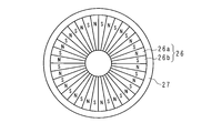
- the outer peripheral edge portion on the outer surface side of the magnets 26a and 26b is chamfered, and a magnet row formed by arranging 18 pairs of chamfered magnetic poles 26 in the circumferential direction is formed into a disk shape as a whole by resin embedding. Yes.
- the magnetic pole pair 26 is resin-molded to form a scattering prevention portion 27 that prevents the magnets 26a and 26b from scattering due to the centrifugal force generated by the rotation of the second rotor 23 at the outer peripheral edge portions of the magnets 26a and 26b. Yes. As shown in FIGS.
- the scattering prevention unit 27 surrounds the outer peripheral edges of the magnets 26a and 26b, and has a cross-sectional saddle shape that regulates the movement of the magnets 26a and 26b to be separated from the disc portion 24 Is an annular member.
- the second rotor unit 2 includes a disk-shaped second magnetic field modulation yoke 28 that modulates the spatial frequency of the magnetic field generated by the second rotor 23.
- the second cylindrical portion 21 is arranged so that the second magnetic field modulation yoke 28 faces the surface of the second rotor 23 on which the magnetic pole pair 26 is arranged in parallel and covers one open end of the second cylindrical portion 21.
- a two-field modulation yoke 28 is supported and fixed.
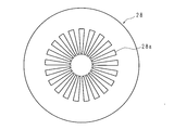
- the second magnetic field modulation yoke 28 includes 21 magnetic bodies 28a arranged at substantially equal intervals along the circumferential direction, and a disk-shaped holding member that holds the plurality of magnetic bodies 28a. Prepare.
- the number of the magnetic bodies 28a is an example, and is appropriately set according to a desired gear ratio.
- the second rotor unit 2 includes a lid portion 29 that covers the other open end of the second cylindrical portion 21.
- a hole is formed in the central portion of the lid 29, and the input / output shaft 25 of the second rotor 23 projects rotatably from the hole.
- the connected rotor unit 3 includes a third cylindrical portion 31 having an outer diameter that is substantially the same as the first and second cylindrical portions 11 and 21.
- the third cylindrical portion 31 is arranged between the first rotor unit 1 and the second rotor unit 2 so that the center lines substantially coincide with each other, and connects the first and second rotor units 1 and 2. ing.
- the thickness of the connecting rotor 33 is shorter than the length of the third cylinder portion 31 in the center line direction, and the connecting rotor 33 is contained inside the third cylinder portion 31.
- the 3rd cylinder part 31 is formed with nonmagnetic materials, such as stainless steel.
- the outer ring of the bearing 32 is press-fitted into the inner peripheral surface of the third cylindrical portion 31, the third cylindrical portion 31 is connected to the connecting rotor 33 via the bearing 32, and the rotation axis is the center line of the third cylindrical portion 31. It is supported so as to be able to rotate so as to substantially match.
- the connecting rotor 33 has a disk-shaped back yoke 34 made of a magnetic material. As shown in FIG. 5A, on the disk surface of the back yoke 34 on the first rotor unit 1 side, an outer surface side magnetized in the thickness direction (upper surface side in FIG. 4) N pole magnet 35a and the outer surface Eighteen sets of fan-shaped magnetic pole pairs 35 each having a side S-pole magnet 35b are arranged at substantially equal intervals along the circumferential direction.
- the outer peripheral edge portion on the outer surface side of the magnets 35a and 35b is chamfered, and a magnet row formed by arranging 18 sets of chamfered magnetic pole pairs 35 in the circumferential direction is formed into a disk shape as a whole by resin embedding,
- column 33a is comprised.
- the disk surfaces of the magnetic pole pair 35 and the first magnetic field modulation yoke 18 are opposed to each other with a gap, and the magnetic pole pair 35 is magnetically coupled to the first rotor 13 via the first magnetic field modulation yoke 18. ing.
- connection rotor 33 is provided with a scattering prevention unit 36 that prevents the magnets 35 a and 35 b from scattering due to the centrifugal force generated by the rotation of the connection rotor 33.
- the configuration of the scattering prevention unit 36 is the same as that of the scattering prevention unit 17.
- the number of the magnetic pole pairs 35 is an example, and is appropriately set according to a desired gear ratio.
- the number of the magnetic pole pairs 16 and the magnetic bodies 18a of the first rotor unit 1 and the number of the magnetic pole pairs 35 of the coupled rotor unit 3 satisfy the following formula (1) (Tetsuya Ikeda, Kenji Nakamura, Osamu Ichinokura "A Consideration on Efficiency Improvement of Permanent Magnet Type Magnetic Gear", Journal of Magnetic Society, 2009, Vol. 33, No. 2, pp. 130-134).
- p2 ns1 ⁇ p1 (1)
- p1 Number of pairs of magnetic pole pairs 16
- p2 Number of pairs of magnetic pole pairs 35
- ns1 Number of magnetic bodies 18a
- the outer surface side (lower surface side in FIG. 4) N-pole magnet 37a magnetized in the thickness direction.
- three sets of fan-shaped magnetic pole pairs 37 composed of the outer surface side S-pole magnets 37b are arranged at substantially equal intervals along the circumferential direction.
- the outer peripheral edge portion on the outer surface side of the magnets 37a and 37b is chamfered, and the magnet row formed by arranging the three chamfered magnetic pole pairs 37 in the circumferential direction is formed into a disk shape as a whole by resin embedding,
- column 33b is comprised.
- the disk surfaces of the magnetic pole pair 37 and the second magnetic field modulation yoke 28 are opposed to each other with a gap, and the magnetic pole pair 37 is magnetically coupled to the second rotor 23 via the second magnetic field modulation yoke 28. ing.
- the connection rotor 33 is provided with a scattering prevention unit 38 that prevents the magnets 37 a and 37 b from scattering due to the centrifugal force generated by the rotation of the connection rotor 33.
- the configuration of the scattering prevention unit 38 is the same as that of the scattering prevention unit 17.
- the number of magnetic pole pairs 37 is an example, and is appropriately set according to a desired gear ratio.
- the number of magnetic pole pairs 26 and magnetic bodies 28a of the second rotor unit 2 and the number of magnetic pole pairs 37 of the connected rotor unit 3 preferably satisfy the following formula (2).
- p4 ns2 ⁇ p3 (2)
- p3 number of pairs of magnetic pole pairs 37
- p4 number of sets of magnetic pole pairs 26
- ns2 number of magnetic bodies 28a
- FIG. 8 is a conceptual diagram showing a combination of the number of magnet arrays and magnetic bodies constituting each unit.
- the magnetic gear device includes three units, that is, a first rotor unit 1, a second rotor unit 2 and a connected rotor unit 3.
- the connection method of each unit is not specifically limited, each unit may be connected by a screw or may be connected by welding.
- “M3” and “M18” indicate three magnetic pole pairs and 18 magnetic pole pairs, respectively, and “J21” indicates 21 magnetic bodies.
- the connection rotor 33 rotates by the magnetic interaction between the magnetic pole pairs 16 and 35 which the 1st rotor 13 and the connection rotor 33 have.
- the gear ratio of the rotational speed of the 1st rotor 13 and the connection rotor 33 is represented by the following formula (4).
- ⁇ 1 rotational speed of the connected rotor 33
- the gear ratio of the first rotor 13 and the second rotor 23 is expressed by the following formula (7).
- ⁇ 2 / ⁇ 0 1/36.
- ⁇ 2 / ⁇ 0 p1 / (ns1-p1) ⁇ p3 / (ns2-p3) (7)
- FIG. 9 is a conceptual diagram illustrating another combination example of each unit. Similar to the magnetic gear device shown in FIG. 8, the magnetic gear device is composed of three units, but a desired gear ratio can be obtained by replacing some units with other units having different numbers of magnetic pole pairs and magnetic bodies.
- the magnetic gear device having the above can be easily configured.
- the first rotor unit 1 is replaced with a first rotor unit 101 having six pairs of magnetic poles and 20 magnetic members, and the connected rotor unit 3 has a pair of magnetic poles.
- the connected rotor unit 3 has a pair of magnetic poles.
- the direction of rotation can be converted to the opposite direction.
- the rotation directions of the input / output shaft 15 and the input / output shaft 25 can be reversed.
- the rotation speed ratio is represented by the following formula (9).
- the first rotor 13 and the connecting rotor 33 rotate in the same direction.
- p2 ns1 + p1 (8)
- ⁇ 1 / ⁇ 0 p1 / (ns1 + p1) (9)
- ratio of a rotational speed is represented by following formula (11).
- the rotations of the second rotor 23 and the connecting rotor 33 are in the same direction.
- the axial gap structure is adopted, and the first and second rotor units 1 and 2 are magnetically coupled by the disk-shaped coupling rotor unit 3.
- a high gear ratio can be realized with a small magnetic gear device.
- first rotor unit 1, the second rotor unit 2, and the like are connected by a flat disk-shaped connecting rotor 33 in which a magnetic pole pair 35 and a magnetic pole pair 37 are arranged in the circumferential direction on each disk surface of the back yoke 34. Therefore, it is possible to minimize the increase in size of the magnetic gear device in the direction of the rotation axis due to the connection, and it is possible to reduce the size of the magnetic gear device.
- a magnetic gear device having a desired gear ratio can be easily manufactured by exchanging a part of the three units constituting the magnetic gear device.
- the rotation direction of the input / output shafts 15 and 25 can be changed to the same direction or the opposite direction by exchanging a part of the three units constituting the magnetic gear device.
- the scattering prevention portions 17, 27, 36, and 38 by providing the scattering prevention portions 17, 27, 36, and 38, the first rotor 13 having the magnetic pole pair 16, the second rotor 23 having the magnetic pole pair 26, and the connecting rotor 33 having the magnetic pole pairs 35 and 37.
- the first magnetic field modulation yoke 18 and the second magnetic field modulation yoke 28 are fixed. As a result, the structure of the magnetic gear device is simplified, the number of parts is reduced, and the cost can be reduced.
- first and second magnetic field modulation yokes 18 and 28 are fixed and the first and second rotors 13 and 23 are rotated.
- 23 may be fixed and the first and second magnetic field modulation yokes 18 and 28 may be rotated.
- the first and second magnetic field modulation yokes 18 and 28 may be provided with an input / output shaft, an input / output ring and the like for inputting / outputting rotational force.
Landscapes
- Engineering & Computer Science (AREA)
- Power Engineering (AREA)
- General Engineering & Computer Science (AREA)
- Mechanical Engineering (AREA)
- Dynamo-Electric Clutches, Dynamo-Electric Brakes (AREA)
Abstract
Description
特許文献2に係る磁気ギア装置は、一般的なアキシャルギャップ構造を採用しており、小型化及びギア比の向上には限界がある。
第1磁石列及び第1磁性体列が相対的に回転した場合、第1磁石列の磁場は変調され、該第1磁石列の磁極対の数と異なる次数の周波数成分を有する回転磁場が生成される。回転磁場の回転速度は、第1磁石列又は第1磁性体列の回転速度と異なり、回転磁場は磁極対及び磁性体の数に応じたギア比で回転する。第2磁石列及び第2磁性体列によって生成される回転磁場も同様の性質を有する。連結器は、このように変調された第1磁石列の回転磁場と、第2磁石列の回転磁場とに磁気的に結合し、第1磁石列及び第2磁石列を連結する。
従って、第1磁石列又は第1磁性体列に回転力が与えられた場合、該回転力は、連結器を介して所定の加減速比で第2磁石列又は第2磁性体列に伝達される。回転速度は、第1磁石列及び第1磁性体列側と、第2磁石列及び第2磁性体列側とにおいて2段階で加速又は減速される。逆も同様であり、第2磁石列又は第2磁性体列に回転力が与えられた場合、該回転力は、連結器を介して所定の加減速比で第1磁石列又は第1磁性体列に伝達される。
なお、本発明においては、磁気ギア装置を用いて回転力を伝達する際、第1磁石列及び第1磁性体列のいずれを固定しても良い。同様に、第2磁石列及び第2磁性体列のいずれを固定しても良い。
なお、本発明には第1連結磁石列と、第2連結磁石列との間に円盤状のバックヨークを介装させる構成も含まれる。バックヨークを設けた場合、第1及び第2磁石列と、第1及び第2連結回転子との結合力が大きくなるため、伝達可能な回転力は増大し、脱調を防ぐことができる。
図1は本実施形態に係る磁気ギア装置の一構成例を示した側断面図、図2は第1回転子ユニット1の一構成例を示した側断面図、図3A及び図3Bは第1回転子13及び第1磁場変調ヨーク(第1磁性体列)18の一構成例を示した底面図、図4は連結回転子ユニット3の一構成例を示した側断面図、図5A及び図5Bは連結回転子33の一構成例を示した上面図及び底面図、図6は、第2回転子ユニット2の一構成例を示した側断面図、図7A及び図7Bは第2回転子23及び第2磁場変調ヨーク(第2磁性体列)28の一構成例を示した上面図である。
本発明の実施形態に係る磁気ギア装置は円柱状をなし、回転軸が略一致するように配置された円盤状の第1回転子ユニット1及び第2回転子ユニット2と、第1及び第2回転子ユニット1、2間に配され、各ユニットを磁気的に連結する連結回転子ユニット(連結器)3とを備える。
なお本明細書において略一致とは、設計上は一致を意味しており、製作の過程で発生する機械加工等で必要な寸法公差や誤差を含み略一致と表記した。また、設計上の一致は、必ずしも完全な一致を意味するものでは無く、第1回転子13、第2回転子23及び連結回転子33が磁気的ないし機械的に結合して回転し、回転力を伝達することが可能な範囲において中心軸が不一致となる場合も含み得る。
磁石16a,16bの外面側の外周縁部分は面取り加工されており、面取り加工された3組の磁極対16を周方向に配してなる磁石列は樹脂埋め込みによって全体として円盤状に成形されている。磁極対16を樹脂モールドすることによって、磁石16a,16bの外周縁部には、第1回転子13の回転による遠心力によって磁石16a,16bが飛散することを防止する飛散防止部17が形成されている。具体的には、飛散防止部17は、図2及び図3Aに示すように、磁石16a,16bの外周縁を囲繞しており、円板部14から離れようとする磁石16a,16bの動きを規制する断面鈎状をなす円環部材である。
なお本明細書において等間隔とは、設計上は等間隔を意味しており、製作の過程で発生する機械加工等で必要な寸法公差や誤差を含み略等間隔と表記した。また、設計上の等間隔は、必ずしも完全な一致を意味するものでは無く、第1回転子13、第2回転子23及び連結回転子33が磁気的ないし機械的に結合して回転し、回転力を伝達することが可能な範囲において配置間隔が不一致となる場合も含み得る。
磁極対26を樹脂モールドすることで、磁石26a、26bの外周縁部には第2回転子23の回転による遠心力によって磁石26a,26bが飛散することを防止する飛散防止部27が形成されている。飛散防止部27は、図6及び図7Bに示すように、磁石26a,26bの外周縁を囲繞しており、円板部24から離れようとする磁石26a,26bの動きを規制する断面鈎状をなす円環部材である。
磁極対35の数は一例であり、所望のギア比に応じて適宜設定される。ただし、第1回転子ユニット1の磁極対16及び磁性体18a並びに連結回転子ユニット3の磁極対35の数は下記式(1)を満たす構成が好ましい(池田哲也・中村健二・一ノ倉理、「永久磁石式磁気ギアの効率向上に関する一考察」、磁気学会論文誌、2009年、33巻、2号、130-134頁)。
p2=ns1±p1…(1)
但し、
p1:磁極対16の組数
p2:磁極対35の組数
ns1:磁性体18aの個数
磁極対37の数は一例であり、所望のギア比に応じて適宜設定される。ただし、第1回転子ユニット1側と同様、第2回転子ユニット2の磁極対26及び磁性体28a並びに連結回転子ユニット3の磁極対37の数は下記式(2)を満たす構成が好ましい。
p4=ns2±p3…(2)
但し、
p3:磁極対37の組数
p4:磁極対26の組数
ns2:磁性体28aの個数
図8は各ユニットを構成する磁石列及び磁性体の数の組み合わせを示す概念図である。図8に示すように、磁気ギア装置は3つのユニット、即ち第1回転子ユニット1、第2回転子ユニット2及び連結回転子ユニット3から構成される。連結回転子ユニット3を間に介して第1及び第2回転子ユニット1、2を連結することによって、本実施形態の磁気ギア装置を製造することができる。各ユニットの連結方法は特に限定されるものでは無いが、各ユニットはネジで連結しても良いし、溶接にて連結しても良い。図8中、「M3」及び「M18」は、それぞれ3組の磁極対及び18組の磁極対を示し、「J21」は21個の磁性体を示している。
p2=ns1-p1…-(3)
ω1/ω0=-p1/(ns1-p1)・・・(4)
但し、
ω0:第1回転子13の回転速度
ω1:連結回転子33の回転速度
p4=ns2-p3…(5)
ω2/ω1=-p3/(ns2-p3)・・・(6)
但し、
ω2:第2回転子23の回転速度
ω2/ω0=p1/(ns1-p1)×p3/(ns2-p3)・・・(7)
図9に示す例の場合、(-6/14)×(-1/6)=1/14のギア比を有する磁気ギア装置を得ることができる。
p2=ns1+p1…(8)
ω1/ω0=p1/(ns1+p1)・・・(9)
p4=ns2+p3…(10)
ω2/ω1=p3/(ns2+p3)・・・(11)
2 第2回転子ユニット
3 連結回転子ユニット
11 第1筒部
12 軸受
13 第1回転子(第1磁石列)
16 磁極対
16a,16b 磁石
18 第1磁場変調ヨーク
21 第2筒部
22 軸受
23 第2回転子(第2磁石列)
26 磁極対
26a,26b 磁石
28 第2磁場変調ヨーク
31 第3筒部
32 軸受
33 連結回転子
33a 第1連結磁石列
33b 第2連結磁石列
34 バックヨーク
35,37 磁極対
35a,35b,37a,37b 磁石
Claims (4)
- 周方向に沿って複数の磁極対がそれぞれ配された円盤状の第1磁石列と、
周方向に沿って複数の磁性体がそれぞれ配されており、前記第1磁石列が生成する磁場の空間周波数を変調する円盤状の第1磁性体列と、
中心線が前記第1磁石列の中心線と略一致しており、周方向に沿って複数の磁極対がそれぞれ配された円盤状の第2磁石列と、
周方向に沿って複数の磁性体がそれぞれ配されており、前記第2磁石列が生成する磁場の空間周波数を変調する円盤状の第2磁性体列と、
前記第1磁性体列及び前記第2磁性体列の間に配されており、前記第1磁性体列及び前記第2磁性体列を介して前記第1磁石列及び前記第2磁石列を磁気的に連結する円盤状の連結器と
を備える磁気ギア装置。 - 前記連結器は、
中心線が前記第1磁石列の中心線と略一致しており、前記第1磁性体列によって変調された磁場に対応する複数の磁極対がそれぞれ周方向に沿って配された円盤状の第1連結磁石列と、
中心線が前記第2磁石列の中心線と略一致しており、前記第2磁性体列によって変調された磁場に対応する複数の磁極対がそれぞれ周方向に沿って配された円盤状の第2連結磁石列と
を備え、
前記第1連結磁石列及び前記第2連結磁石列は前記周方向において相対的に固定されている
請求項1に記載の磁気ギア装置。 - 前記第1磁石列及び前記第1磁性体列を支持し、ユニット化する第1筒部と、
前記第2磁石列及び前記第2磁性体列を支持し、ユニット化する第2筒部と、
前記第1連結磁石列及び第2連結磁石列を支持し、ユニット化する第3筒部と
を備える請求項2に記載の磁気ギア装置。 - 前記第1磁石列及び第2磁石列は軸受にて、回転可能に前記第1筒部及び第2筒部にそれぞれ支持されており、前記第1連結磁石列及び第2連結磁石列は軸受にて、一体回転可能に前記第3筒部に支持されている
請求項3に記載の磁気ギア装置。
Priority Applications (3)
| Application Number | Priority Date | Filing Date | Title |
|---|---|---|---|
| CN201680055270.XA CN108138934A (zh) | 2015-09-24 | 2016-09-21 | 磁齿轮装置 |
| US15/761,004 US20180248463A1 (en) | 2015-09-24 | 2016-09-21 | Magnetic Gear Device |
| JP2017541566A JP6693527B2 (ja) | 2015-09-24 | 2016-09-21 | 磁気ギア装置 |
Applications Claiming Priority (2)
| Application Number | Priority Date | Filing Date | Title |
|---|---|---|---|
| JP2015-187310 | 2015-09-24 | ||
| JP2015187310 | 2015-09-24 |
Publications (1)
| Publication Number | Publication Date |
|---|---|
| WO2017051823A1 true WO2017051823A1 (ja) | 2017-03-30 |
Family
ID=58386647
Family Applications (1)
| Application Number | Title | Priority Date | Filing Date |
|---|---|---|---|
| PCT/JP2016/077841 Ceased WO2017051823A1 (ja) | 2015-09-24 | 2016-09-21 | 磁気ギア装置 |
Country Status (4)
| Country | Link |
|---|---|
| US (1) | US20180248463A1 (ja) |
| JP (1) | JP6693527B2 (ja) |
| CN (1) | CN108138934A (ja) |
| WO (1) | WO2017051823A1 (ja) |
Cited By (1)
| Publication number | Priority date | Publication date | Assignee | Title |
|---|---|---|---|---|
| JP2022174399A (ja) * | 2021-05-11 | 2022-11-24 | 国立大学法人東北大学 | 磁気歯車装置 |
Families Citing this family (2)
| Publication number | Priority date | Publication date | Assignee | Title |
|---|---|---|---|---|
| CN113949246B (zh) * | 2021-09-30 | 2023-03-31 | 国家电投集团科学技术研究院有限公司 | 轴向磁通的磁齿轮 |
| CN113991968B (zh) * | 2021-11-03 | 2023-11-14 | 大连交通大学 | 一种双励磁双调制盘式永磁齿轮 |
Citations (4)
| Publication number | Priority date | Publication date | Assignee | Title |
|---|---|---|---|---|
| JPS51156350U (ja) * | 1975-06-06 | 1976-12-13 | ||
| JP2010106940A (ja) * | 2008-10-29 | 2010-05-13 | Osaka Univ | 磁気波動歯車装置および磁気伝達減速機 |
| JP2012241763A (ja) * | 2011-05-17 | 2012-12-10 | Katsuhiro Hirata | 磁気変速装置 |
| WO2013011809A1 (ja) * | 2011-07-15 | 2013-01-24 | 日立金属株式会社 | 磁気ギア装置 |
Family Cites Families (8)
| Publication number | Priority date | Publication date | Assignee | Title |
|---|---|---|---|---|
| US3382386A (en) * | 1968-05-07 | Ibm | Magnetic gears | |
| US3579003A (en) * | 1969-07-31 | 1971-05-18 | Robert C Gray | Magnetic braking system |
| US7084548B1 (en) * | 2003-07-11 | 2006-08-01 | Gabrys Christopher W | Low cost high speed electrical machine |
| CN101404440B (zh) * | 2008-11-17 | 2012-06-13 | 哈尔滨工业大学 | 基于空间磁导调制的大力矩无接触式永磁齿轮变速箱 |
| WO2012014596A1 (ja) * | 2010-07-29 | 2012-02-02 | 日立金属株式会社 | 磁気ギア装置及び保持部材 |
| CN102808919A (zh) * | 2011-05-30 | 2012-12-05 | 余虹锦 | 一种新型横向磁场的磁性传动齿轮副 |
| JP5862764B2 (ja) * | 2012-03-27 | 2016-02-16 | 日立金属株式会社 | 周波数変換装置 |
| CN102857069B (zh) * | 2012-09-08 | 2015-05-06 | 余虹锦 | 轴向平面磁场的少极差磁导谐波式磁性齿轮副 |
-
2016
- 2016-09-21 US US15/761,004 patent/US20180248463A1/en not_active Abandoned
- 2016-09-21 CN CN201680055270.XA patent/CN108138934A/zh active Pending
- 2016-09-21 WO PCT/JP2016/077841 patent/WO2017051823A1/ja not_active Ceased
- 2016-09-21 JP JP2017541566A patent/JP6693527B2/ja active Active
Patent Citations (4)
| Publication number | Priority date | Publication date | Assignee | Title |
|---|---|---|---|---|
| JPS51156350U (ja) * | 1975-06-06 | 1976-12-13 | ||
| JP2010106940A (ja) * | 2008-10-29 | 2010-05-13 | Osaka Univ | 磁気波動歯車装置および磁気伝達減速機 |
| JP2012241763A (ja) * | 2011-05-17 | 2012-12-10 | Katsuhiro Hirata | 磁気変速装置 |
| WO2013011809A1 (ja) * | 2011-07-15 | 2013-01-24 | 日立金属株式会社 | 磁気ギア装置 |
Cited By (2)
| Publication number | Priority date | Publication date | Assignee | Title |
|---|---|---|---|---|
| JP2022174399A (ja) * | 2021-05-11 | 2022-11-24 | 国立大学法人東北大学 | 磁気歯車装置 |
| JP7648998B2 (ja) | 2021-05-11 | 2025-03-19 | 国立大学法人東北大学 | 磁気歯車装置 |
Also Published As
| Publication number | Publication date |
|---|---|
| US20180248463A1 (en) | 2018-08-30 |
| JPWO2017051823A1 (ja) | 2018-07-12 |
| CN108138934A (zh) | 2018-06-08 |
| JP6693527B2 (ja) | 2020-05-13 |
Similar Documents
| Publication | Publication Date | Title |
|---|---|---|
| JP6265569B2 (ja) | 環状磁極部材及び磁気波動歯車装置 | |
| JP6417207B2 (ja) | モータ | |
| US10862369B2 (en) | Power unit and motor unit for wave gear speed reducer | |
| CN104011972A (zh) | 混合动力励磁式旋转电机 | |
| JP5817260B2 (ja) | 磁気ギア装置 | |
| JPWO2015140941A1 (ja) | 永久磁石型電動機の回転子 | |
| JP6693527B2 (ja) | 磁気ギア装置 | |
| JP7466854B2 (ja) | 磁気歯車装置 | |
| KR101282613B1 (ko) | 영구자석을 이용한 가감속 장치 | |
| JP6584296B2 (ja) | 3軸能動制御型磁気軸受及びその組立方法 | |
| JP2012244671A (ja) | アキシャルギャップモータのロータ | |
| CN115210990B (zh) | 磁性齿轮传动旋转电机以及定子的制造方法 | |
| JP6332094B2 (ja) | ロータ、電動モータ | |
| JP5453933B2 (ja) | 電磁ユニット | |
| JP7531436B2 (ja) | 磁気変調ギヤ装置 | |
| CN202068246U (zh) | 一种磁通量泄漏小的新型电动机 | |
| JP5639876B2 (ja) | 回転電機 | |
| JP2013106417A (ja) | ロータ及びモータ | |
| JPH03256555A (ja) | 偏平ロータ形pmステップモータ | |
| JP2026007478A (ja) | 磁気変調ギヤのシリーズ及び磁気変調ギヤ | |
| JP2016211667A (ja) | 磁気式歯車装置 | |
| JP2010187505A5 (ja) | ||
| JP2011125098A (ja) | ステータ | |
| WO2012086613A1 (ja) | 回転電機 | |
| JP4392417B2 (ja) | 回転子側面にコイルを有した永久磁石式回転電機 |
Legal Events
| Date | Code | Title | Description |
|---|---|---|---|
| 121 | Ep: the epo has been informed by wipo that ep was designated in this application |
Ref document number: 16848611 Country of ref document: EP Kind code of ref document: A1 |
|
| ENP | Entry into the national phase |
Ref document number: 2017541566 Country of ref document: JP Kind code of ref document: A |
|
| WWE | Wipo information: entry into national phase |
Ref document number: 15761004 Country of ref document: US |
|
| NENP | Non-entry into the national phase |
Ref country code: DE |
|
| 122 | Ep: pct application non-entry in european phase |
Ref document number: 16848611 Country of ref document: EP Kind code of ref document: A1 |