WO2017022795A1 - フォイル軸受 - Google Patents
フォイル軸受 Download PDFInfo
- Publication number
- WO2017022795A1 WO2017022795A1 PCT/JP2016/072799 JP2016072799W WO2017022795A1 WO 2017022795 A1 WO2017022795 A1 WO 2017022795A1 JP 2016072799 W JP2016072799 W JP 2016072799W WO 2017022795 A1 WO2017022795 A1 WO 2017022795A1
- Authority
- WO
- WIPO (PCT)
- Prior art keywords
- fluororesin
- layer
- sliding layer
- foil
- bearing
- Prior art date
Links
Images


Classifications
-
- F—MECHANICAL ENGINEERING; LIGHTING; HEATING; WEAPONS; BLASTING
- F16—ENGINEERING ELEMENTS AND UNITS; GENERAL MEASURES FOR PRODUCING AND MAINTAINING EFFECTIVE FUNCTIONING OF MACHINES OR INSTALLATIONS; THERMAL INSULATION IN GENERAL
- F16C—SHAFTS; FLEXIBLE SHAFTS; ELEMENTS OR CRANKSHAFT MECHANISMS; ROTARY BODIES OTHER THAN GEARING ELEMENTS; BEARINGS
- F16C33/00—Parts of bearings; Special methods for making bearings or parts thereof
- F16C33/02—Parts of sliding-contact bearings
- F16C33/04—Brasses; Bushes; Linings
- F16C33/20—Sliding surface consisting mainly of plastics
- F16C33/203—Multilayer structures, e.g. sleeves comprising a plastic lining
-
- F—MECHANICAL ENGINEERING; LIGHTING; HEATING; WEAPONS; BLASTING
- F16—ENGINEERING ELEMENTS AND UNITS; GENERAL MEASURES FOR PRODUCING AND MAINTAINING EFFECTIVE FUNCTIONING OF MACHINES OR INSTALLATIONS; THERMAL INSULATION IN GENERAL
- F16C—SHAFTS; FLEXIBLE SHAFTS; ELEMENTS OR CRANKSHAFT MECHANISMS; ROTARY BODIES OTHER THAN GEARING ELEMENTS; BEARINGS
- F16C17/00—Sliding-contact bearings for exclusively rotary movement
- F16C17/02—Sliding-contact bearings for exclusively rotary movement for radial load only
- F16C17/024—Sliding-contact bearings for exclusively rotary movement for radial load only with flexible leaves to create hydrodynamic wedge, e.g. radial foil bearings
-
- F—MECHANICAL ENGINEERING; LIGHTING; HEATING; WEAPONS; BLASTING
- F16—ENGINEERING ELEMENTS AND UNITS; GENERAL MEASURES FOR PRODUCING AND MAINTAINING EFFECTIVE FUNCTIONING OF MACHINES OR INSTALLATIONS; THERMAL INSULATION IN GENERAL
- F16C—SHAFTS; FLEXIBLE SHAFTS; ELEMENTS OR CRANKSHAFT MECHANISMS; ROTARY BODIES OTHER THAN GEARING ELEMENTS; BEARINGS
- F16C17/00—Sliding-contact bearings for exclusively rotary movement
- F16C17/04—Sliding-contact bearings for exclusively rotary movement for axial load only
- F16C17/042—Sliding-contact bearings for exclusively rotary movement for axial load only with flexible leaves to create hydrodynamic wedge, e.g. axial foil bearings
-
- F—MECHANICAL ENGINEERING; LIGHTING; HEATING; WEAPONS; BLASTING
- F16—ENGINEERING ELEMENTS AND UNITS; GENERAL MEASURES FOR PRODUCING AND MAINTAINING EFFECTIVE FUNCTIONING OF MACHINES OR INSTALLATIONS; THERMAL INSULATION IN GENERAL
- F16C—SHAFTS; FLEXIBLE SHAFTS; ELEMENTS OR CRANKSHAFT MECHANISMS; ROTARY BODIES OTHER THAN GEARING ELEMENTS; BEARINGS
- F16C33/00—Parts of bearings; Special methods for making bearings or parts thereof
- F16C33/02—Parts of sliding-contact bearings
- F16C33/04—Brasses; Bushes; Linings
- F16C33/20—Sliding surface consisting mainly of plastics
- F16C33/201—Composition of the plastic
-
- F—MECHANICAL ENGINEERING; LIGHTING; HEATING; WEAPONS; BLASTING
- F16—ENGINEERING ELEMENTS AND UNITS; GENERAL MEASURES FOR PRODUCING AND MAINTAINING EFFECTIVE FUNCTIONING OF MACHINES OR INSTALLATIONS; THERMAL INSULATION IN GENERAL
- F16C—SHAFTS; FLEXIBLE SHAFTS; ELEMENTS OR CRANKSHAFT MECHANISMS; ROTARY BODIES OTHER THAN GEARING ELEMENTS; BEARINGS
- F16C2208/00—Plastics; Synthetic resins, e.g. rubbers
- F16C2208/20—Thermoplastic resins
- F16C2208/30—Fluoropolymers
Definitions
- the present invention relates to a foil bearing that supports a shaft that rotates at high speed.
- a shaft rotating at an extremely high speed is often supported by an oil-lubricated rolling bearing or an oil dynamic pressure bearing.
- an oil-lubricated rolling bearing or an oil dynamic pressure bearing when it is difficult to lubricate with liquids such as lubricating oil, when it is difficult to separately provide auxiliary equipment for lubricating oil circulation system from the viewpoint of improving energy efficiency, or when resistance due to liquid shear becomes a problem
- air dynamic pressure bearings are used.
- a foil bearing is a bearing that supports a load by forming a bearing surface with a foil made of a thin plate having low rigidity and low bending rigidity, and allowing the thin plate to bend.
- the inner peripheral surface of the bearing is constituted by a thin plate called a top foil, and the outer peripheral side is supported by a back foil.
- This back foil is a member that enables elastic deformation of the top foil.
- the clearance of a general dynamic pressure bearing is on the order of (1/1000) of the diameter. If the shaft has a diameter of about several millimeters, the gap is about several ⁇ m, and the amount of gap management in an environment where tolerances during manufacturing and temperature changes are severe becomes extremely strict. On the other hand, in the case of a foil bearing, a gap of about several tens of ⁇ m can be provided, and manufacturing and gap management are easy.
- Foil bearings repeatedly contact and slide between the shaft and the bearing surface when the shaft floats or stops. In this case, adhesion occurs on the sliding surface, increasing the friction torque, and consequently the bearing surface. May result in seizure and damage. In order to improve the durability performance of the bearing, it is necessary to reduce the damage of both the shaft and the bearing surface when they contact each other. As one of the methods, it is known that a film containing molybdenum disulfide or graphite is applied to a shaft or a bearing surface (Patent Document 1).
- Patent Document 2 As a film formed on the bearing surface, an example in which molybdenum disulfide is applied on both surfaces of the top foil in order to improve lubricity (Patent Document 2), nickel plating, chromium plating, titanium nitride, amorphous carbon film, etc.
- coatings with good wear resistance such as vapor-deposited coatings, plating with dispersed solid lubricants such as molybdenum disulfide, graphite and fluororesin, and coatings with good lubricity such as resin coating (Patent Document 3) It has been known.
- a sliding member or a fluororesin-coated composite material a sliding member composed of a fluororesin irradiated with ionizing radiation (Patent Document 4), after forming an unfired and uncrosslinked fluororesin layer on a substrate Baked at a temperature equal to or higher than the melting point of the fluororesin, and then baked the uncrosslinked fluororesin layer at a temperature within a specific range below the melting point of the fluororesin in a low oxygen concentration atmosphere and with a specific irradiation.
- Patent Document 4 a sliding member composed of a fluororesin irradiated with ionizing radiation
- Cross-linked fluororesin composite material for irradiating a dose of radiation (Patent Document 5), engineering plastic layer formed of engineering plastic alone or of a material mainly composed of engineering plastic, and fluororesin that covers the surface of this engineering plastic layer Engineers by irradiating the layers with ionizing radiation to crosslink the fluororesin Excellent scratch resistance can be obtained by using an engineering plastic that can form a layer having a pencil hardness of 4H or higher at 30 ° C.
- Patent Document 6 A fluororesin coating material (Patent Document 6), a fluororesin layer that is intimately crosslinked on a substrate having a maximum surface roughness Ry of 20 ⁇ m or less, or on the surface of an etched substrate There is known a sliding member (Patent Document 7) and the like.
- a sliding material provided with a crosslinked PTFE coating obtained by crosslinking a polytetrafluoroethylene (hereinafter referred to as PTFE) resin made of the above fluororesin alone has improved wear resistance as compared with an uncrosslinked fluororesin coating.
- the wear resistance is inferior to a diamond-like carbon (hereinafter referred to as DLC) film or a hard metal film applied to the surface of the foil bearing.
- DLC diamond-like carbon
- hard coatings such as DLC have excellent wear resistance, but are applied to foil bearings due to cracking, adverse effects on the flexibility of the foil, and deformation of the foil due to thermal stress during film formation. It is difficult to increase the film thickness. As a result, there is a problem that sufficient film life cannot be obtained and long-term stability of the foil bearing cannot be obtained.
- the present invention has been made to cope with such problems, has excellent adhesion to the foil, can reduce torque at the start, and is durable regardless of the type of working fluid such as oil and gas.
- An object of the present invention is to provide a foil bearing having a sliding layer made of a cross-linked fluororesin coating that is excellent and can increase the film thickness.
- the foil bearing of the present invention comprises a bearing surface that is formed of a thin foil having flexibility, includes a support portion so that the foil can be elastically deformed, and is provided in the foil in accordance with the rotation of the rotating side member.
- a fluid film is formed in a bearing gap between the bearing surface and the second bearing surface of the rotation side member facing the bearing surface, and the rotation side member is supported by the pressure.
- the foil has a sliding layer on at least one of the front surface and the back surface, and at least one bearing surface of the first bearing surface and the second bearing surface has a sliding layer, and the sliding layer has at least The surface and its vicinity have a crosslinked fluororesin layer.
- the sliding layer has the following six aspects.
- the bearing surface has a base layer containing a heat-resistant resin and a first fluororesin, and a second fluororesin layer on the surface of the base layer, and the heat-resistant resin includes oxygen atoms, It is a resin containing at least one atom of a nitrogen atom and a sulfur atom in at least the main chain of the polymer structure, and the second fluororesin layer is a cross-linked fluororesin layer in which the surface and the vicinity thereof are cross-linked.
- It has a base layer containing a heat-resistant resin and a first fluororesin on the bearing surface, and a second fluororesin layer on the surface of the base layer, and the heat-resistant resin includes oxygen atoms,
- the resin contains at least one atom of nitrogen atom and sulfur atom in at least the main chain of the polymer structure, and the second fluororesin layer is a cross-linked fluororesin layer cross-linked from the sliding layer surface to the substrate surface.
- the sliding layer is made of a fluororesin layer, and the fluororesin layer has a cross-linked structure in which the fluororesin present in the vicinity of the sliding layer and its vicinity has a three-dimensional structure, The fluororesin present in the vicinity has an uncrosslinked structure having a two-dimensional structure, and the content of the three-dimensional structure continuously decreases from the surface of the sliding layer toward the surface in contact with the substrate.
- the fluororesin layer is a cross-linked fluororesin layer that is cross-linked from the surface of the sliding layer to the surface in contact with the substrate.
- the sliding layer is a sliding layer made of a resin composition, and this resin composition is a mixed resin composition of a fluororesin and a heat-resistant resin soluble in a solvent,
- the content ratio of the heat-resistant resin is larger on the base material side of the bearing than the surface side of the sliding layer with respect to the blending ratio of the entire mixed resin composition, and the content ratio of the fluororesin is the mixed resin composition It is contained more on the surface side of the sliding layer than on the base material side, relative to the blending ratio of the whole product,
- the fluororesin has a three-dimensional structure in which the surface of the sliding layer and the vicinity thereof are crosslinked, and a two-dimensional structure in which the surface of the sliding layer on the substrate side and the vicinity thereof are uncrosslinked.
- the sliding layer is a sliding layer made of a resin composition, and this resin composition is a mixed resin composition of a fluororesin and a heat resistant resin soluble in a solvent,
- the content ratio of the heat-resistant resin is larger on the base material side of the bearing than the surface side of the sliding layer with respect to the blending ratio of the entire mixed resin composition, and the content ratio of the fluororesin is the mixed resin composition It is contained more on the surface side of the sliding layer than on the base material side, relative to the blending ratio of the whole product,
- the fluororesin is a cross-linked fluororesin layer that is cross-linked from the surface of the sliding layer to the surface on the substrate side.
- the surface roughness of the sliding member which is the mating surface of the bearing surface made of the sliding layer, is RaR0.8 ⁇ m or less.
- the surface roughness Ra is an arithmetic average roughness defined by JIS B0601-2001.
- the bearing surface has a sliding layer having a cross-linked fluororesin layer on the surface and in the vicinity thereof, so that the friction and wear durability performance of the foil bearing is improved. Moreover, the torque at the time of starting can be reduced by the cross-linked fluororesin layer having a small frictional resistance.
- FIG. 1 shows a radial foil bearing of a type called a bump type
- FIG. 1 (a) shows an axial sectional view
- FIG. 1 (b) shows a partially enlarged sectional view
- a foil bearing 1 includes a thin plate of metal or the like whose inner peripheral surface is called a top foil 3, a back foil 4 that elastically deforms the top foil such as a thin metal plate that has a corrugated outer periphery, and a foil holder that is a fixed portion
- the shaft 2 is arranged in the bearing 1.
- the top foil 3 has one end 3 a in the circumferential direction as a free end, and the other end 3 b is fixed to the foil holder 5.
- a sliding layer 6 made of a crosslinked fluororesin is formed on the sliding surface 3 c of the top foil 3. Note that the sliding surface of the shaft 2 or the sliding surfaces of both the top foil 3 and the shaft 2 and the surface of the top foil 3 opposite to the surface on which the top foil 3 slides with the shaft 2 are made of a cross-linked fluororesin. A layer can be provided.
- Rotating the shaft 2 in the direction of arrow A causes a working fluid such as air to be drawn between the shaft 2 and the top foil 3 to generate fluid pressure.
- a working fluid such as air
- a fluid film is formed in the bearing gap between the sliding surface 2a of the shaft 2 and the sliding surface 3a of the top foil 3, and the shaft 2 floats.
- the sliding surface 2a of the shaft 2 and the sliding surface 3a of the top foil 3 are not in contact with each other and can be operated semipermanently.
- the rotational speed is insufficient.
- FIG. 2 shows a perspective view of a bearing portion of a thrust foil bearing
- FIG. 2 (a) shows a leaf foil bearing
- FIG. 2 (b) shows a perspective view of a bump foil bearing
- the leaf foil bearing 7 shown in FIG. 2A is provided with a plurality of leaf-type foils 8 at a plurality of locations in the circumferential direction on the end face of the disc-shaped foil holder 9.
- the foil 8 has one end in the circumferential direction as a free end, and the other end is fixed to the foil holder 9.
- a sliding layer made of a crosslinked fluororesin is formed on the sliding surface of the foil 8.
- the bump foil bearing 10 shown in FIG. 2B is an example in which a back foil 11 is provided on the back surface of the top foil 8 on which a sliding layer made of a crosslinked fluororesin is formed on the surface.
- the cross-linked fluororesin coating has flexibility unique to the resin material and can be formed thicker than a hard coating.
- the thickness of the coating greatly affects the lifetime of the coating by sliding, and a longer lifetime can be obtained compared to other hard coatings by forming a thick crosslinked fluororesin coating having excellent wear resistance.
- the sliding layer made of the mixed resin composition has a linear expansion coefficient closer to that of the metal substrate than the fluororesin alone due to the blending of the heat resistant resin.
- the linear expansion coefficient ( ⁇ 10 ⁇ 5 / k) is 1.21 for iron, 10.0 for PTFE, and 3.06 for aromatic polyamideimide resin
- the linear expansion coefficient of the mixed resin composition is about iron. It will approach. As a result, warpage of the sliding layer surface of the foil and cracking of the coating can be prevented.
- the layer thickness of the sliding layer is preferably 10 ⁇ m or more. When it is less than 10 ⁇ m, it is easy to wear and the effect of reducing the surface pressure cannot be obtained.
- the upper limit of the layer thickness is a range in which dimensional accuracy when a foil bearing is obtained.
- the surface roughness Ra of the sliding surface of the counterpart material with respect to the cross-linked fluororesin film is preferably 0.8 ⁇ m or less, or a surface shape that does not have a tip projection that causes digging.
- the foil material is a flexible, elastically deformable metal material, such as stainless steel such as SUS301 and SUS304, ferrous metal material such as SK material (carbon tool steel), phosphor bronze, brass, beryllium copper, etc. Examples include copper alloys and nickel alloys such as Inconel.
- the shaft material is preferably an iron-based metal material, and examples thereof include bearing steel used for rolling bearings, carburized steel, carbon steel for machine structure, cold rolled steel, hot rolled steel, and the like.
- the iron-based metal material is adjusted to a predetermined surface hardness by quenching and tempering after processing into a shaft shape. For example, in the case of an iron-based metal material cage using chromium molybdenum steel (SCM415), it is preferable to use an iron-based metal material whose Hv value is adjusted to 484 to 595.
- the sliding layer comprising the above six aspects will be described.
- FIG. 1 A sectional view of the sliding layer is shown in FIG.
- a sliding layer is provided on at least one of the first bearing surface provided on the foil and the second bearing surface of the other member facing the first bearing surface, for example, the shaft surface.
- the sliding layer 12 includes a base layer 14 formed on the surface of the metal material 13 and a cross-linked fluororesin layer 15 formed on the surface of the base layer 14.
- the underlayer 14 is a mixed resin of a fluororesin represented by a black circle and a heat resistant resin represented by a white circle on the drawing.
- the fluororesin contained in the base layer 14 and the cross-linked fluororesin layer 15 is a cross-linked fluororesin layer formed by cross-linking at least the vicinity of the surface layer.
- the sliding layer 12 has a three-dimensional structure in which the fluororesin present on the surface that is not in contact with the base material and the neighboring layer has a three-dimensional structure, and the fluorine that is present on the surface in contact with the base material and the neighboring layer.
- the resin has a two-dimensional structure, and the content of the three-dimensional structure of the fluororesin existing between the sliding layer surface and the substrate surface continuously decreases from the sliding layer surface toward the substrate surface. ing.
- the sliding layer 12 is an inclined material in which the cross-linking ratio decreases from the surface layer toward the surface of the iron-based metal material 3.
- the surface of the fluororesin existing on the surface that is not in contact with the base material and its neighboring layers has a three-dimensional structure, and the entire portion of the fluororesin layer is not limited to being made only of a fluororesin having a three-dimensional structure, This part may contain a part of the two-dimensional fluororesin.
- the fluororesin existing on the surface in contact with the substrate and its neighboring layers has a two-dimensional structure is not limited to the fact that the entire portion of the fluororesin layer is made of only a two-dimensional fluoropolymer.
- This part may contain a part of a three-dimensional fluororesin.
- the layer thickness t 1 of the cross-linked fluororesin layer 15 is 10 to 90%, preferably 25 to 25% of the layer thickness t of the sliding layer, which is the total thickness with the layer thickness t 2 of the underlayer 14. 75%.
- the heat resistant resin is a resin containing at least one atom of an oxygen atom, a nitrogen atom and a sulfur atom together with carbon atoms in at least the main chain of the polymer structure. Further, it is a resin that does not thermally decompose when fired to form a sliding layer.
- “not thermally decomposed” means a resin that does not start thermal decomposition within the temperature and time for firing the underlayer and the upper layer film.
- the heat resistant resin examples include epoxy resin, polyester resin, amideimide resin, imide resin, etherimide resin, imidazole resin, polyethersulfone resin, polysulfone resin, polyetheretherketone resin, and silicone resin.
- the urethane resin and acrylic resin which prevent the shrinkage
- a resin mainly containing an aromatic ring is preferable because of excellent heat resistance.
- Preferred heat resistant resins include aromatic amide imide resins and aromatic imide resins.
- the first fluororesin can be used as long as it is a resin that can be dispersed in the form of particles in the aqueous coating liquid that forms the base layer.
- PTFE particles tetrafluoroethylene-perfluoro (alkyl vinyl ether) copolymer (hereinafter referred to as PFA) particles, tetrafluoroethylene-hexafluoropropylene copolymer (hereinafter referred to as FEP) particles, Or these 2 or more types can be used preferably.
- the aqueous coating solution for forming the underlayer includes a nonionic surfactant such as polyoxyethylene alkyl ether, an inorganic pigment such as carbon black, N-methyl-2-pyrrolidone
- a nonionic surfactant such as polyoxyethylene alkyl ether
- an inorganic pigment such as carbon black
- An aprotic polar solvent that is arbitrarily mixed with water, such as water, and water as a main solvent are blended.
- an antifoamer, a desiccant, a thickener, a leveling agent, a repellency inhibitor, etc. can be mix
- examples of the aqueous coating solution for forming the undercoat layer include primer paints EK series and ED series manufactured by Daikin Industries, Ltd.
- the second fluororesin layer is a fluororesin layer that is formed on the surface of the underlayer and can be cross-linked by radiation.
- the first fluororesin and the second fluororesin may be the same or different, but it is preferable to use the same fluororesin.
- the second fluororesin include PTFE, PFA, FEP, ethylene / tetrafluoroethylene copolymer (ETFE), and the like. These resins can be used alone or as a mixture. Of these, PTFE which is excellent in heat resistance and slidability is preferable.
- the second fluororesin layer can be obtained by applying and drying an aqueous dispersion in which PTFE resin particles are dispersed.
- the metal material, the base layer, and the second fluororesin layer are in close contact with each other without providing an adhesive layer.
- a method for manufacturing the sliding layer will be described below.
- Metal surface treatment process The metal material is preferably immersed in an organic solvent such as petroleum benzine and subjected to ultrasonic degreasing for about 5 minutes to 1 hour.
- Coating process of water-based coating solution that forms the underlayer In order to improve the dispersibility of the aqueous dispersion before application of the aqueous coating liquid for forming the underlayer, it is redispersed by rotating it at 40 rpm, for example, for 1 hour using a ball mill. This re-dispersed aqueous coating solution is filtered using a 100 mesh wire netting and applied using a spray method.
- Drying process of aqueous coating solution for forming the underlayer After applying the aqueous coating solution, it is dried.
- drying conditions for example, drying in a thermostat at 90 ° C. for about 30 minutes is preferable.
- the coating process of the aqueous coating solution that forms the second fluororesin layer Before the aqueous coating liquid for forming the second fluororesin layer, in order to improve the dispersibility of the aqueous dispersion, it is redispersed by, for example, rotating at 40 rpm for 1 hour using a ball mill. Without firing the underlayer, the re-dispersed aqueous coating solution is filtered using a 100-mesh wire mesh on the surface of the dried underlayer, and is applied using a spray method.
- Drying step of the aqueous coating solution for forming the second fluororesin layer After applying the aqueous coating solution, it is dried.
- drying conditions for example, drying in a thermostat at 90 ° C. for about 30 minutes is preferable.
- a coating method of a base layer and a 2nd fluororesin layer what can form a film, such as a dipping method and a brush coating method other than a spray method, can be used.
- the spray method is preferable in view of making the surface roughness and coating shape of the coating as small as possible and considering the uniformity of the layer thickness.
- Firing process After drying of the second fluororesin layer, in the heating furnace, in the air, a temperature equal to or higher than the melting point of the second fluororesin, preferably (melting point (Tm) + 30 ° C.) to (melting point (Tm) + 100 ° C.), 5 to Within the range of 40 minutes, the base layer and the second fluororesin layer are fired.
- the first and second fluororesins are PTFE, they are preferably fired in a heating furnace at 380 ° C. for 30 minutes.
- the irradiation temperature is from a temperature 30 ° C. lower than the melting point of the second fluororesin layer to a temperature not higher than 50 ° C. of the melting point, preferably 10 ° C. lower than the melting point of the second fluororesin layer.
- the fluororesin layer is cross-linked by irradiating with radiation at a temperature of 20 ° C. or higher and an irradiation dose of more than 250 kGy and 750 kGy or less.
- Examples of radiation include ⁇ rays (particle beams of helium-4 nuclei emitted from radionuclides that undergo ⁇ decay), ⁇ rays (negative electrons and positrons emitted from nuclei), and electron beams (almost constant kinetic energy).
- Particle beam such as electron beam, generally generated by accelerating thermionic electrons in vacuum; gamma ray (emitted and absorbed by transitions between energy levels of nuclei and elementary particles, pair annihilation of elementary particles, pair production, etc.) Ionizing radiation such as an electromagnetic wave having a short wavelength).
- electron beams and ⁇ rays are preferable, and electron beams are more preferable.
- an electron beam has advantages such as easy availability of an electron beam irradiation apparatus, simple irradiation operation, and the ability to employ a continuous irradiation process.
- the cross-linking of the fluororesin layer does not proceed sufficiently except in the temperature range where the irradiation temperature is 30 ° C. lower than the melting point of the second fluororesin layer to 50 ° C. higher than the melting point.
- the hardness of the fluororesin layer does not advance sufficiently.
- the range of oxygen concentration is preferably 0 to 300 ppm.
- an inert atmosphere by nitrogen gas injection is preferable from the viewpoint of operability and cost.
- the irradiation dose is 250 kGy or less, crosslinking is insufficient, the wear amount is large, and the metal substrate may be exposed.
- the irradiation dose exceeds 750 kGy, crosslinking proceeds more than necessary, and the hardness of the coating increases, so that the coating becomes brittle and damage to the coating such as peeling may easily occur.
- the surface hardness of the sliding layer expressed as indentation hardness, can be adjusted to 52 to 90 MPa, preferably 60 to 85 MPa.
- the wear amount is large, and the metal substrate may be exposed.
- the indentation hardness is higher than 90 MPa, the hardness of the film increases, and the film becomes brittle and damage to the film such as peeling may easily occur.
- the fluororesin layer is irradiated with radiation under a temperature range where the irradiation temperature is 30 ° C. lower than the melting point of the second fluororesin layer to a temperature not higher than 50 ° C. of the melting point and the irradiation dose is more than 250 kGy and 750 kGy or less.
- the melting point of the second fluororesin layer can be lowered so that the melting point of the second fluororesin layer is 280 to 310 ° C., preferably 280 to 301 ° C.
- the melting point is higher than 310 ° C., the amount of wear is large, and the metal substrate may be exposed.
- the melting point is lower than 280 ° C., the hardness of the film increases, and the film becomes brittle and damage to the film such as peeling may easily occur.
- Acceleration voltage upon irradiation is 40 kV or more and less than 500 kV, preferably 50 to 100 kV. When it is less than 40 kV, the penetration of the electron beam into the vicinity of the surface layer of the second fluororesin layer becomes shallow, and when it is 500 kV or more, the entire first and second fluororesin layers are cross-linked.
- the intensity of the radiation is attenuated inside the fluororesin, so that radiation can reach the vicinity of the irradiated surface sufficiently, but radiation cannot reach other surfaces.
- the vicinity of the surface of the second fluororesin layer can be crosslinked.
- test piece A sliding layer was formed on a metal flat plate of 30 mm ⁇ 30 mm and 2 mm thickness made of SPCC.
- a primer coating model number: EK-1909S21R
- a top coating model number: EK-3700C21R manufactured by Daikin was used for the second fluororesin layer.
- the drying time was 30 minutes in a constant temperature bath at 90 ° C., and the base layer and the second fluororesin layer were simultaneously fired in a heating furnace at 380 ° C. for 30 minutes. Thereafter, the specimen was irradiated with an electron beam from the sliding layer side under the following conditions.
- Equipment used EB engine manufactured by Hamamatsu Photonics Co., Ltd.
- Test piece coating example of experiment example 1 PTFE coating (irradiation dose: 0 kGy, layer thickness: 20 ⁇ m)
- Experimental Example 2 PTFE coating (irradiation dose: 500 kGy, layer thickness: 20 ⁇ m)
- Experimental Example 3 PTFE coating (irradiation dose: 1000 kGy, layer thickness: 20 ⁇ m)
- Experimental Example 2 showed an excellent specific wear amount although the friction coefficient increased.
- the measurement is performed using an NMR apparatus JNM-ECX400 manufactured by JEOL Ltd., and a suitable measurement nuclide ( 19 F), resonance frequency (376.2 MHz), MAS (Magic Angle Spinning) rotation speed (15 and 12 kHz), sample amount (About 70 ⁇ L in a 4 mm solid state NMR tube), a cycle time (10 seconds) and a measurement temperature (about 24 ° C.).
- the results are shown in FIGS. 4 shows NMR of the surface layer of Experimental Example 1, and FIG. 5 shows an enlarged view of the NMR chart of Experimental Example 2, respectively.
- the NMR of the surface layer of Experimental Example 3 is shown in FIG. 4 to 6, the upper stage represents the MAS rotational speed 15 kHz, and the lower stage represents the MAS rotational speed 12 kHz.
- FIG. 7 is a graph obtained by normalizing the signal intensity at ⁇ 82 ppm, the intensity of which increases with crosslinking, with the signal intensity at ⁇ 122 ppm as the main signal.
- the upper part represents measured values
- the lower part represents graphs. It is considered that the higher the signal intensity ratio is, the more the degree of crosslinking proceeds.
- ⁇ 122 ppm is the signal of the F atom in the —CF 2 —CF 2 — bond
- ⁇ 82 ppm is the signal of the F atom of —CF 3 in the —CF 2 —CF 3 bond. Therefore, the signals of ⁇ 82 ppm and ⁇ 162 ppm at a MAS rotational speed of 15 kHz, and ⁇ 58 ppm, ⁇ 90 ppm, ⁇ 154 ppm and ⁇ 186 ppm at a MAS rotational speed of 12 kHz are spinning side bands (SSB). A broad signal is observed in the range of ⁇ 122 ppm to ⁇ 130 ppm hidden by the ⁇ 122 ppm signal.
- SSB spinning side bands
- This signal is the signal of the F atom of —CF 2 — in the —CF 2 —CF 3 bond that should be observed at ⁇ 126 ppm. Therefore, the uncrosslinked second fluororesin layer not irradiated with radiation has signals of ⁇ 122 ppm attributed to —CF 2 —CF 2 — bonds, ⁇ 82 ppm and ⁇ 126 ppm attributed to —CF 2 —CF 3 , respectively. Represented by NMR chart.
- the normalized signal intensity ratio increases as the irradiation dose increases. It can be seen that a crosslinked structure appears clearly at an irradiation dose of 500 kGy.
- the sliding layer 12 includes a base layer 14 formed on the surface of the metal material 13 and a cross-linked fluororesin layer 15 formed on the surface of the base layer 14.
- the cross-linked fluororesin layer 15 is a cross-linked fluororesin layer cross-linked from the sliding layer surface to the substrate surface.
- It has a base layer containing a heat-resistant resin and a first fluororesin on the surface of the metal material, and a second fluororesin layer on the surface of the base layer, and the heat-resistant resin includes oxygen atoms, nitrogen, together with carbon atoms.
- the sliding layer having the above aspect (1) is a resin containing at least one atom of an atom and a sulfur atom in at least the main chain of the polymer structure.
- a cross-linked fluororesin layer was obtained in the same manner as in the above (1) except that EPS-3000 manufactured by NHV Corporation was used as the electron beam irradiation apparatus and the acceleration voltage was changed to 1.16 MV. When solid 19 F MAS NMR of the surface of the sliding layer and the surface on the substrate side was measured, it was found that the surface was cross-linked from the surface of the second fluororesin layer to the substrate surface.
- the sliding layer 12 includes a cross-linked fluororesin layer 15 formed on the surface of the metal material 13.
- the cross-linked fluororesin layer 15 has a cross-linked structure in which one surface 15a not in contact with the metal substrate and a fluororesin existing in the vicinity thereof have a three-dimensional structure, and the fluororesin layer is in contact with the metal substrate.
- the fluororesin existing on the other surface 14a and its vicinity 14 has an uncrosslinked structure, and the content of the three-dimensional structure of the fluororesin existing between the one surface and the other surface continuously changes. This is a crosslinked fluororesin layer.
- the sliding layer 12 was formed on the surface of the metal material 13 in the same manner as in the production process of the crosslinked fluororesin having the above aspect (1) except that the underlayer was not used.
- solid 19 F MAS NMR of the surface 15a of this sliding layer was measured, it was found that the surface of the sliding layer was crosslinked.
- the sliding layer 12 was formed by using an EPS-3000 manufactured by NHV Corporation as an electron beam irradiation device at an acceleration voltage of 1.16 MV, similarly to the formation of the sliding layer having the aspect (2). .
- the sliding layer 12 includes a cross-linked fluororesin layer 15 formed on the surface of the metal material 13.
- the crosslinked fluororesin layer 15 has a crosslinked structure consisting of a three-dimensional structure from the metal substrate surface to the sliding layer surface. When solid 19 F MAS NMR of the surface of the sliding layer was measured, it was found that the surface of the sliding layer was crosslinked.
- the sliding layer is a mixed resin composition of a fluororesin and a heat-resistant resin that is soluble in a solvent. Compared to the mixing ratio of the initial mixture, the content of the heat-resistant resin is higher than that of the surface side of the sliding layer. The content of the fluororesin is contained more on the surface side of the sliding layer than on the substrate side. Further, the fluororesin has a three-dimensional structure in which the surface of the sliding layer and the vicinity thereof are crosslinked, and a two-dimensional structure in which the side surface of the substrate of the sliding layer and the vicinity thereof are uncrosslinked. 9A and 9B are sectional views of the sliding layer. FIG.
- FIG. 9A is an example in which the surface of the sliding layer and the fluororesin in the vicinity thereof have a three-dimensional structure
- FIG. 9B continuously changes the fluororesin from the three-dimensional structure to the two-dimensional structure. This is an example having an inclined structure.
- the sliding layer 12 formed on the surface of the foil bearing is formed on the surface of the metal material 13.
- the sliding layer 12 is a mixed resin composition of a fluororesin and a heat resistant resin.
- the heat resistant resin is in the base layer side region 14 and the fluororesin is in the surface side region 15 of the sliding layer. Each of them is contained in a larger amount than the total blending ratio.
- the fluororesin has a three-dimensional structure on the surface of the sliding layer and the vicinity thereof, and the base material layer side has an uncrosslinked two-dimensional structure.
- FIG. 9B shows an example in which the fluororesin has an inclined structure that continuously changes from a three-dimensional structure to a two-dimensional structure.
- the sliding layer 12 provided on the bearing cross-section 11 is a mixed resin composition of a fluororesin and a heat resistant resin.
- the heat resistant resin is in the base layer side region 14 and the fluororesin is in the surface side region 15 of the sliding layer.
- each is contained in a larger amount than the total blending ratio of the mixed resin composition.
- the sliding layer 12 has an inclined structure in which the polymer structure of the fluororesin continuously changes from the three-dimensional structure to the two-dimensional structure from the surface 15a side of the layer thickness t to the surface of the base material side 14a. ing.
- the fluororesin can be used as long as it is a dispersion or solution that can form a coating film on the surface of the substrate.
- the dispersion is preferably a fluororesin that can be dispersed in the form of particles in an aqueous coating solution.
- the fluororesin include PTFE resin, PFA copolymer, FEP copolymer, and ethylene / tetrafluoroethylene copolymer. These resins can be used alone or as a mixture. Of these, PTFE which is excellent in heat resistance and slidability is preferable.
- the heat-resistant resin that constitutes the sliding layer is a resin that does not thermally decompose when the sliding layer is formed by applying and drying a dispersion and / or solution on the surface of the substrate and then baking.
- “not thermally decomposed” means a resin that does not start thermal decomposition within the temperature and time for firing the mixed resin.
- the start of thermal decomposition can be measured by a thermal decomposition apparatus such as TG.
- the heat resistant resin is preferably an aromatic resin that is soluble in an aprotic polar solvent. Excellent heat resistance and radiation resistance, heat resistant resin becomes liquid when coating film is formed, fluororesin with lower surface energy is distributed on the sliding layer surface side, and heat resistant resin with higher surface energy than fluororesin is on the substrate side As a result, a sliding layer having excellent surface lubricity and excellent adhesion to the substrate is formed. The sliding property is further improved by crosslinking the fluororesin layer on the surface side.
- Examples of aprotic polar solvents include N-methyl-2-pyrrolidone, N, N-dimethylformamide, N, N-diethylformamide, N, N-dimethylacetamide, dimethyl sulfoxide and the like.
- N-methyl-2-pyrrolidone having a boiling point of 202 ° C. and mixed with water at an arbitrary ratio is preferable.
- Aromatic resins that dissolve in the aprotic polar solvent include aromatic polyamideimide resins, solvent-soluble aromatic polyimide resins, solvent-soluble aromatic polyamide resins, aromatic polybenzimidazole resins, aromatic polybenzoxazole resins, and the like. These may be used alone or in combination. Among these, aromatic polyamideimide resins that are excellent in solvent solubility and heat resistance of the coating are preferable.
- the aromatic polyamideimide resin is a resin having an aromatic ring, an imide bond and an amide bond in the molecule.
- aromatic polyamide-imide resins include polyamide imides, aromatics produced from aromatic primary diamines such as diphenylmethane diamine and aromatic tribasic acid anhydrides such as mono- or diacyl halide derivatives of trimellitic anhydride.
- aromatic polyamide-imide resins include polyamide imides, aromatics produced from aromatic primary diamines such as diphenylmethane diamine and aromatic tribasic acid anhydrides such as mono- or diacyl halide derivatives of trimellitic anhydride.
- polyamidoimides produced from a tribasic acid anhydride and an aromatic diisocyanate compound for example, diphenylmethane diisocyanate.
- polyamidoimide having a larger ratio of imide bonds than amide bonds aromatic, aliphatic or there are polyamide imides produced from alicyclic diisocyanate compounds and aromatic tetrabasic acid dianhydrides and aromatic tribasic acid anhydrides, and any polyamideimide resin can be used.
- resins that can be used in combination with the aromatic resin include epoxy resins, polyester resins, etherimide resins, polyethersulfone resins, polysulfone resins, polyetheretherketone resins, and silicone resins.
- the urethane resin and acrylic resin which prevent the shrinkage
- the mixing ratio of the fluororesin and the heat resistant resin in the mixed resin composition forming the sliding layer is preferably 1 to 50 parts by volume of the heat resistant resin, with the total of the fluororesin and the heat resistant resin being 100 parts by volume. Is 5 to 30 parts by volume, more preferably 5 to 10 parts by volume. If the ratio of the heat-resistant resin is less than 1 part by volume, the difference in the coefficient of linear expansion between the metal substrate and the fluororesin becomes large, the tensile stress is applied to the sliding layer, and when the film is formed on the foil surface, Separation occurs, and in the case of a bearing, cracks are likely to occur on the surface. Moreover, when the ratio of heat resistant resin exceeds 50 volume parts, the ratio of a fluororesin will decrease and slidability will become inadequate.
- aqueous coating solution in which the fluororesin and the heat-resistant resin are mixed is prepared, and this coating solution is applied on a substrate, dried, and then fired to prepare a mixed resin composition film before uncrosslinking.
- the aqueous coating solution is obtained by dispersing fine particles of a fluororesin and a heat-resistant resin in water as a main solvent.
- an aprotic polar solvent such as N-methyl-2-pyrrolidone which dissolves the heat-resistant resin and is mixed with water at an arbitrary ratio.
- the aqueous coating liquid contains a nonionic surfactant such as polyoxyethylene alkyl ether, an inorganic pigment such as carbon black, and water as a main solvent.
- an antifoamer, a desiccant, a thickener, a leveling agent, a repellency inhibitor, etc. can be mix
- the mixed resin composition film before non-crosslinking is coated and dried using a dispersion type coating liquid in which fine particles of fluororesin are dispersed in a solution in which the above heat-resistant resin is dissolved or dispersed in an aprotic polar solvent. It can be manufactured by firing. Thereafter, the sliding layer 12 made of the cross-linked fluororesin was formed on the surface of the metal material 13 in the same manner as in the production process of the cross-linked fluororesin having the above aspect (1) except that the base layer was not used. When solid 19 F MAS NMR of the surface 15a of this sliding layer was measured, it was found that the surface of the sliding layer was crosslinked.
- the sliding layer 12 is a mixed resin composition of a fluororesin and a heat-resistant resin, and the content ratio of the heat-resistant resin is more on the base material side of the bearing than the surface side of the sliding layer compared to the blending ratio of the initial mixture. In addition, the content ratio of the fluororesin is contained more on the surface side of the sliding layer than on the base material side.
- the fluororesin is crosslinked by using an EPS-3000 manufactured by NHV Corporation as an electron beam irradiation apparatus and an acceleration voltage of 1.16 MV.
- the surface of the sliding layer is cross-linked from the vicinity of the substrate. When solid 19 F MAS NMR of the entire sliding layer was measured, it was found that the sliding layer was crosslinked.
- Example 1 Comparative Example 1
- Comparative Example 2 A sliding layer made of crosslinked PTFE having a thickness of 50 ⁇ m was formed on the surface of the foil of the leaf foil bearing shown in FIG. Further, a sliding layer made of uncrosslinked crosslinked PTFE having a thickness of 50 ⁇ m was formed using the material of Experimental Example 1 to obtain Comparative Example 1.
- a DLC film having a thickness of 2 ⁇ m was formed on the surface of the foil of the leaf foil bearing shown in FIG. Using these leaf foil bearings, lifting and stopping by rotating the shaft was set as one cycle, and the durability of the coating against sliding when the number of cycles was repeated was confirmed. The results are shown in Table 2.
- the leaf foil bearing of Example 1 in which the cross-linked PTFE coating was formed as compared with the leaf foil bearing in which the DLC coating of Comparative Example 2 was formed was superior in durability performance, and after 25,000 cycles. As a result, the film remained. In addition, the influence on the flexibility of the foil by applying a film having a thickness of 50 ⁇ m was not observed.
- Comparative Example 1 regarding the presence or absence of cross-linking of PTFE it can be confirmed that the durability performance is improved by the cross-linking treatment by radiation irradiation.
- the present invention can be used for all foil bearings such as radial foil bearings and thrust foil bearings because the friction and wear durability performance of the sliding surfaces of the foil bearings can be improved and the torque at the start can be reduced.
Landscapes
- Engineering & Computer Science (AREA)
- General Engineering & Computer Science (AREA)
- Mechanical Engineering (AREA)
- Physics & Mathematics (AREA)
- Fluid Mechanics (AREA)
- Support Of The Bearing (AREA)
- Sliding-Contact Bearings (AREA)
- Laminated Bodies (AREA)
Abstract
フォイルとの密着性に優れ、かつ始動時のトルクを低減でき、さらに耐久性に優れ、被膜厚さを厚くできる摺動層を有するフォイル軸受を提供する。可撓性を有する薄いフォイルで軸受面を構成し、このフォイルが弾性変形可能となるように支持部を備え、回転側部材の回転に伴ってフォイルに設けた第1軸受面とこれに対向する回転側部材の第2軸受面との間の軸受隙間に流体膜が形成され、その圧力で回転側部材が支持され、フォイルの表面および裏面の少なくとも1つの面に摺動層を有し、第1軸受面および第2軸受面の少なくとも1つの軸受面が摺動層を有し、この摺動層は少なくとも表面およびその近傍が架橋フッ素樹脂層を有する。
Description
本発明は高速で回転する軸を支持するフォイル軸受に関する。
軸受装置において、極めて高速で回転する軸は、油潤滑の転がり軸受や油動圧軸受で支持されることが多い。しかし、潤滑油などの液体による潤滑が困難な場合や、エネルギー効率を向上させる観点から潤滑油循環系の補機を別途設けることが困難な場合や、液体のせん断による抵抗が問題になる場合等には空気動圧軸受を使用することが多い。
空気動圧軸受の中で、軸受面が剛体で近似できる一般的な動圧軸受の場合、回転速度に応じた隙間の管理が重要であり、安定限界を超えるとホワールと呼ばれる振れ回りが生じる。したがって、厳密に隙間を設定しなければ所定の回転速度で運転することができないという問題がある。
空気動圧軸受の中で、軸受面が剛体で近似できる一般的な動圧軸受の場合、回転速度に応じた隙間の管理が重要であり、安定限界を超えるとホワールと呼ばれる振れ回りが生じる。したがって、厳密に隙間を設定しなければ所定の回転速度で運転することができないという問題がある。
これに対し、フォイル軸受は、曲げに対して剛性の低い可撓性を有する薄板からなるフォイルで軸受面を構成し、薄板のたわみを許容して荷重を支持する軸受である。
ラジアルフォイル軸受の場合、軸受の内周面がトップフォイルと呼ばれる薄板で構成されており、その外周側がバックフォイルで支持されている。このバックフォイルはトップフォイルの弾性変形を可能とする部材である。軸の回転時には,軸とトップフォイル内径面の間に空気の膜が形成される。この軸受の場合、フォイルの可撓性により軸の回転速度や荷重、周囲温度等の運転条件に応じた適切な隙間が自動的に形成されるため、安定性に優れ、上記一般的な空気動圧軸受と比較して高速回転での使用が可能である。一般的な動圧軸受の隙間は直径の(1/1000)のオーダーである。直径数mm程度の軸であれば数μm程度の隙間であり、製造時の公差および温度変化の激しい環境下における隙間量管理は極めて厳しくなる。一方、フォイル軸受の場合には数十μm程度の隙間を設けることが可能であり、製造や隙間管理が容易である。
ラジアルフォイル軸受の場合、軸受の内周面がトップフォイルと呼ばれる薄板で構成されており、その外周側がバックフォイルで支持されている。このバックフォイルはトップフォイルの弾性変形を可能とする部材である。軸の回転時には,軸とトップフォイル内径面の間に空気の膜が形成される。この軸受の場合、フォイルの可撓性により軸の回転速度や荷重、周囲温度等の運転条件に応じた適切な隙間が自動的に形成されるため、安定性に優れ、上記一般的な空気動圧軸受と比較して高速回転での使用が可能である。一般的な動圧軸受の隙間は直径の(1/1000)のオーダーである。直径数mm程度の軸であれば数μm程度の隙間であり、製造時の公差および温度変化の激しい環境下における隙間量管理は極めて厳しくなる。一方、フォイル軸受の場合には数十μm程度の隙間を設けることが可能であり、製造や隙間管理が容易である。
フォイル軸受は、軸の浮上・停止時などで軸と軸受面とで接触・摺動を繰り返すことになるが、この場合、摺動面に凝着が生じ、摩擦トルクの増大、ひいては軸受面の焼付き、破損に至ることがある。軸受の耐久性能を向上させるためには、軸と軸受面が接触した際の双方の損傷を少なくする必要がある。その方法の一つとして、軸や軸受面に二硫化モリブデンあるいは黒鉛を含む被膜を施すことが知られている(特許文献1)。軸受面に形成される被膜として、潤滑性を高めるために、トップフォイルの両面に二硫化モリブデンを塗布した例(特許文献2)、ニッケルめっき、クロムめっき、窒化チタンや非晶質カーボン被膜等の蒸着被膜など、耐摩耗性の良い被膜、または二硫化モリブデンや、黒鉛、フッ素樹脂等の固体潤滑剤を分散しためっきや、樹脂コーティング等の潤滑性の良い被膜を設けた例(特許文献3)が知られている。
一方、摺動部材またはフッ素樹脂被覆複合材料として、電離性放射線を照射したフッ素樹脂によって構成した摺動部材(特許文献4)、基材上に未焼成かつ未架橋のフッ素樹脂層を形成した後、該フッ素樹脂の融点以上の温度で焼成し、次いで、焼成した未架橋フッ素樹脂層を、低酸素濃度雰囲気下、該フッ素樹脂の融点未満の特定の範囲内の温度で、かつ、特定の照射線量の放射線を照射する架橋フッ素樹脂複合材料(特許文献5)、エンジニアリングプラスチックのみから又はエンジニアリングプラスチックを主体とする材質により形成されているエンジニアリングプラスチック層、およびこのエンジニアリングプラスチック層の表面を被覆するフッ素樹脂層に、電離放射線を照射してフッ素樹脂を架橋させることにより、エンジニアリングプラスチック層とフッ素樹脂層との優れた接着力が得られること、そして、エンジニアリングプラスチックとして、30℃で4H以上の鉛筆硬度を有する層を形成できるものを用いることにより、優れた耐スクラッチ性を有するフッ素樹脂被覆材(特許文献6)、表面粗度の最大高さRyを20μm以下とした基材上、または、エッチング処理された基材の表面上に、密着して架橋されたフッ素樹脂層を設けた摺動部材(特許文献7)等が知られている。
しかしながら、上記フッ素樹脂単体からなるポリテトラフルオロエチレン(以下、PTFEという)樹脂を架橋した架橋PTFE被膜を施した摺動材料は、未架橋のフッ素樹脂被膜と比較して耐摩耗性が向上するが、フォイル軸受表面に施されたダイヤモンドライクカーボン(以下、DLCという)膜や硬質の金属被膜などと比較すると耐摩耗性に劣るという問題がある。
一方、DLCなどの硬質被膜は、耐摩耗性に優れる一方で、割れの発生や、フォイルの可撓性への悪影響、製膜時の熱応力によるフォイルの変形などから、フォイル軸受へ適用する場合に膜厚を厚くすることは困難である。結果として十分な被膜寿命が得られず、長期的なフォイル軸受の安定性能が得られないという問題がある。
一方、DLCなどの硬質被膜は、耐摩耗性に優れる一方で、割れの発生や、フォイルの可撓性への悪影響、製膜時の熱応力によるフォイルの変形などから、フォイル軸受へ適用する場合に膜厚を厚くすることは困難である。結果として十分な被膜寿命が得られず、長期的なフォイル軸受の安定性能が得られないという問題がある。
本発明はこのような問題に対処するためになされたものであり、フォイルとの密着性に優れ、かつ始動時のトルクを低減でき、さらに油やガスなど作動流体の種類を問わず耐久性に優れ、被膜厚さを厚くできる架橋フッ素樹脂被膜からなる摺動層を有するフォイル軸受の提供を目的とする。
本発明のフォイル軸受は、可撓性を有する薄いフォイルで軸受面を構成し、このフォイルが弾性変形可能となるように支持部を備え、回転側部材の回転に伴ってフォイルに設けた第1軸受面と、これに対向する上記回転側部材の第2軸受面との間の軸受隙間に流体膜が形成され、その圧力で回転側部材が支持されるフォイル軸受である。このフォイルの表面および裏面の少なくとも1つの面に摺動層を有し、また、第1軸受面および第2軸受面の少なくとも1つの軸受面が摺動層を有し、これら摺動層は少なくとも表面およびその近傍が架橋フッ素樹脂層を有することを特徴とする。
上記摺動層は、以下の6つの態様からなることを特徴とする。
(1)軸受面に耐熱性樹脂および第一のフッ素樹脂を含む下地層と、この下地層表面に第二のフッ素樹脂層とを有し、上記耐熱性樹脂は、炭素原子と共に、酸素原子、窒素原子および硫黄原子の少なくとも1つの原子を高分子構造の少なくとも主鎖に含む樹脂であり、第二のフッ素樹脂層は表面およびその近傍が架橋されてなる架橋フッ素樹脂層である。
(2)軸受面に耐熱性樹脂および第一のフッ素樹脂を含む下地層と、この下地層表面に第二のフッ素樹脂層とを有し、上記耐熱性樹脂は、炭素原子と共に、酸素原子、窒素原子および硫黄原子の少なくとも1つの原子を高分子構造の少なくとも主鎖に含む樹脂であり、第二のフッ素樹脂層は摺動層表面から基材面まで架橋された架橋フッ素樹脂層である。
(3)摺動層がフッ素樹脂層からなり、このフッ素樹脂層は摺動層表面およびその近傍に存在するフッ素樹脂が三次元構造からなる架橋構造を有し、基材と接している面およびその近傍に存在するフッ素樹脂が二次元構造からなる未架橋構造を有し、摺動層表面から基材と接している面に向かって三次元構造の含率が連続的に少なくなっている。
(4)上記フッ素樹脂層は摺動層表面から基材と接している面まで架橋された架橋フッ素樹脂層である。
(4)上記フッ素樹脂層は摺動層表面から基材と接している面まで架橋された架橋フッ素樹脂層である。
(5)摺動層は樹脂組成物からなる摺動層であり、この樹脂組成物はフッ素樹脂と溶媒に可溶する耐熱性樹脂との混合樹脂組成物であり、
上記耐熱性樹脂の含有割合は、混合樹脂組成物全体の配合割合に対して、摺動層の表面側よりも軸受の基材側に多く、また、上記フッ素樹脂の含有割合は、混合樹脂組成物全体の配合割合に対して、基材側よりも摺動層の表面側に多くそれぞれ含まれており、
上記フッ素樹脂は、摺動層の表面およびその近傍が架橋された三次元構造を、摺動層の基材側の面およびその近傍が未架橋の二次元構造をそれぞれ有している。
(6)摺動層は樹脂組成物からなる摺動層であり、この樹脂組成物はフッ素樹脂と溶媒に可溶する耐熱性樹脂との混合樹脂組成物であり、
上記耐熱性樹脂の含有割合は、混合樹脂組成物全体の配合割合に対して、摺動層の表面側よりも軸受の基材側に多く、また、上記フッ素樹脂の含有割合は、混合樹脂組成物全体の配合割合に対して、基材側よりも摺動層の表面側に多くそれぞれ含まれており、
上記フッ素樹脂は、摺動層表面から基材側の面まで架橋された架橋フッ素樹脂層である。
上記耐熱性樹脂の含有割合は、混合樹脂組成物全体の配合割合に対して、摺動層の表面側よりも軸受の基材側に多く、また、上記フッ素樹脂の含有割合は、混合樹脂組成物全体の配合割合に対して、基材側よりも摺動層の表面側に多くそれぞれ含まれており、
上記フッ素樹脂は、摺動層の表面およびその近傍が架橋された三次元構造を、摺動層の基材側の面およびその近傍が未架橋の二次元構造をそれぞれ有している。
(6)摺動層は樹脂組成物からなる摺動層であり、この樹脂組成物はフッ素樹脂と溶媒に可溶する耐熱性樹脂との混合樹脂組成物であり、
上記耐熱性樹脂の含有割合は、混合樹脂組成物全体の配合割合に対して、摺動層の表面側よりも軸受の基材側に多く、また、上記フッ素樹脂の含有割合は、混合樹脂組成物全体の配合割合に対して、基材側よりも摺動層の表面側に多くそれぞれ含まれており、
上記フッ素樹脂は、摺動層表面から基材側の面まで架橋された架橋フッ素樹脂層である。
上記摺動層からなる軸受面の相手面となる摺動部材の表面粗さがRa 0.8μm以下であることを特徴とする。ここで表面粗さRaはJIS B0601-2001で規定される算術平均粗さをいう。
本発明のフォイル軸受は、軸受面が表面およびその近傍に架橋フッ素樹脂層を有する摺動層を有しているので、フォイル軸受の摩擦摩耗耐久性能が向上する。また、摩擦抵抗が小さい架橋フッ素樹脂層により始動時のトルクを低下できる。
フォイル軸受の例を図1に示す。図1はバンプ型と呼ばれる形式のラジアルフォイル軸受を示し、図1(a)は軸方向断面図を、図1(b)は一部拡大断面図をそれぞれ示す。
フォイル軸受1は、軸受内周面がトップフォイル3と呼ばれる金属などの薄板、その外周が波型形状を与えた金属薄板などトップフォイルに弾性変形を与えるバックフォイル4、そして固定部であるフォイルホルダ5から構成され、この軸受1内に軸2が配置される。トップフォイル3は周方向一方の端部3aを自由端とし、他端3bがフォイルホルダ5に固定されている。
トップフォイル3の摺動面3cには架橋フッ素樹脂からなる摺動層6が形成されている。なお、軸2の摺動面、または、トップフォイル3および軸2の両方の摺動面、更にはトップフォイル3が軸2と摺動する面と反対側の面に架橋フッ素樹脂からなる摺動層を設けることができる。
フォイル軸受1は、軸受内周面がトップフォイル3と呼ばれる金属などの薄板、その外周が波型形状を与えた金属薄板などトップフォイルに弾性変形を与えるバックフォイル4、そして固定部であるフォイルホルダ5から構成され、この軸受1内に軸2が配置される。トップフォイル3は周方向一方の端部3aを自由端とし、他端3bがフォイルホルダ5に固定されている。
トップフォイル3の摺動面3cには架橋フッ素樹脂からなる摺動層6が形成されている。なお、軸2の摺動面、または、トップフォイル3および軸2の両方の摺動面、更にはトップフォイル3が軸2と摺動する面と反対側の面に架橋フッ素樹脂からなる摺動層を設けることができる。
軸2が矢印A方向に回転することで空気などの作動流体が軸2とトップフォイル3との間に引き込まれ流体圧力が発生する。その結果、軸2の摺動面2aとトップフォイル3の摺動面3aとの間の軸受隙間に流体膜が形成され軸2が浮上する。軸2が高速回転中は軸2の摺動面2aとトップフォイル3の摺動面3aは非接触となり、半永久的に運転が可能となるが、軸2の停止時や、回転速度が不十分なときは軸2を浮上させる流体圧力が発生しないため、軸2とトップフォイル3表面に形成された架橋フッ素樹脂からなる摺動層6とは接触状態となる。これらを繰り返すことで軸・フォイル間に摩擦・摩耗が生じるが、特定構造の架橋フッ素樹脂被膜からなる摺動層を設けることで、軸・フォイル間に発生する摩擦・摩耗を大幅に低下させることができた。本発明はこのような知見に基づくものである。
フォイル軸受の他の例を図2に示す。図2はスラストフォイル軸受の軸受部の斜視図を示し、図2(a)はリーフフォイル軸受を、図2(b)はバンプフォイル軸受の斜視図をそれぞれ示す。
図2(a)に示すリーフフォイル軸受7は、円盤状のフォイルホルダ9の端面の円周方向複数箇所に、複数のリーフ型のフォイル8が設けられている。フォイル8は周方向一方の端部を自由端とし、他端がフォイルホルダ9に固定されている。フォイル8の摺動面には架橋フッ素樹脂からなる摺動層が形成されている。図示を省略した軸が回転すると、各フォイルの軸受面とこれに対向する軸の端面との間にスラスト軸受隙間が形成され、このスラスト軸受隙間の空気などの流体膜により軸がスラスト方向に非接触支持される。
図2(b)に示すバンプフォイル軸受10は表面に架橋フッ素樹脂からなる摺動層が形成されているトップフォイル8の裏面にバックフォイル11を設けた例である。
フォイル軸受のフォイル摺動面に架橋フッ素樹脂被膜を施すことで、DLCを始めとする他の硬質被膜と比較して格段に被膜寿命が長くなり、また始動トルクを減じる効果が得られた。その理由として、以下の点が挙げられる。
(i)架橋フッ素樹脂被膜は耐摩耗性に優れることに加え、樹脂材料特有の柔軟性を持ち、硬質被膜と比較して厚く製膜することが可能である。被膜の厚さは摺動による被膜の寿命に大きく影響し、耐摩耗性に優れる架橋フッ素樹脂被膜を厚く製膜することで、他の硬質被膜と比較して長寿命が得られる。
(ii)軸とフォイルが接触する際において、軸受表面が硬質であると接触部において大きな接触圧力が生じ、そこから軸、軸受が損傷する。フォイルのエッジ部分は軸の振れ回りの発生などで特に高面圧で接触することが多く損傷する割合が顕著である。一方で架橋フッ素樹脂被膜を施したものは、接触面が樹脂特有の柔軟性を有し、またなじみ性に優れることにより接触面積が増加し、面圧を減じる効果が得られる。
(iii)軸受面の少なくともいずれか一方を架橋フッ素樹脂層とすることで,摺動する相手面に移着膜を形成し、フッ素樹脂同士の摺動になることで低摩擦となる。
(iV)架橋フッ素樹脂被膜が摺動により摩耗した場合、剛体の軸受であれば軸受隙間に変化が生じ、軸受性能に悪影響を与える。一方でフォイル軸受の場合、軸受隙間はフォイルの可撓性により最適に形成される。被膜の基材となるフォイルは被膜の存在により損耗しないためフォイルの可撓性への影響もなく、長期的に安定した性能を得ることができる。
(V)また、回転軸側に架橋フッ素樹脂被膜を形成した場合でも、フォイル軸受の摺動面に摺動層を形成した場合と同様の耐久性能が得られる。フォイル側に架橋フッ素樹脂被膜を形成する場合、主に摺動する部分は負荷圏(図1では重力方向である接触部)であり、負荷圏部分が集中的に損傷し,他の部分の被膜が潤滑に寄与しない可能性がある。一方で回転軸に被膜を形成すると、軸の回転により周方向面すべて摺動部であるため、被膜がより効果的に潤滑、耐摩耗に寄与する。回転軸に被膜を形成する場合、円筒面への製膜、架橋処理を施すために特殊な工程を要し、製膜コストが高くなる可能性がある。一方フォイルに被膜を形成する場合は、フォイル自体はフォイルホルダに挿入前は真直ぐな薄板であるため、容易に製膜、架橋処理を施すことができる。
(Vi)薄板であるフォイルの場合、混合樹脂組成物からなる摺動層は、耐熱性樹脂の配合により、フッ素樹脂単独よりも線膨張係数が金属基材の線膨張係数に近くなる。例えば、線膨張係数(×10-5/k)は鉄が1.21、PTFEが10.0、芳香族ポリアミドイミド樹脂が3.06であるので、混合樹脂組成物の線膨張係数は鉄に近づくことになる。その結果、フォイルの摺動層表面の反りや被膜のひび割れを防ぐことができる。
摺動層の層厚さは10μm以上であることが好ましい。10μm未満であると、摩耗しやすく、面圧を下げる効果が得られない。層厚さの上限としてはフォイル軸受としたときの寸法精度が得られる範囲である。
耐摩擦摩耗性に優れる架橋フッ素樹脂被膜であるが、一方で表面粗さRaが大きな相手材と摺動試験を行なうと、架橋による耐摩耗性向上の効果はほとんど得られず、大きなアブレージョン作用の働く摺動条件の場合、架橋フッ素樹脂被膜の効果が得られない場合がある。そのため、架橋フッ素樹脂被膜に対する相手材の摺動面の表面粗Raは0.8μm以下にする、もしくは掘り起こしが起こるような先端突起のない表面形状にすることが好ましい。
フォイルの材料は可撓性を有し、弾性変形できる金属材料である、SUS301やSUS304などのステンレス鋼、SK材(炭素工具鋼)などの鉄系金属材料、リン青銅、黄銅、ベリリウム銅などの銅合金、インコネルなどのニッケル合金などが挙げられる。
また、軸の材料としては鉄系金属材が好ましく、転がり軸受などに使用される軸受鋼、浸炭鋼、機械構造用炭素鋼、冷間圧延鋼、または熱間圧延鋼等が挙げられる。鉄系金属材は軸形状に加工後、焼入焼戻し処理することで所定の表面硬度に調整する。例えばクロムモリブデン鋼(SCM415)を用いた鉄系金属材製保持器の場合、Hv値が484~595に調整した鉄系金属材を使用することが好ましい。
また、軸の材料としては鉄系金属材が好ましく、転がり軸受などに使用される軸受鋼、浸炭鋼、機械構造用炭素鋼、冷間圧延鋼、または熱間圧延鋼等が挙げられる。鉄系金属材は軸形状に加工後、焼入焼戻し処理することで所定の表面硬度に調整する。例えばクロムモリブデン鋼(SCM415)を用いた鉄系金属材製保持器の場合、Hv値が484~595に調整した鉄系金属材を使用することが好ましい。
上記6つの態様からなる摺動層について説明する。
[上記(1)の態様からなる摺動層]
摺動層の断面図を図3(a)に示す。フォイルに設けた第1軸受面とこれに対向する他方の部材の第2軸受面、例えば軸の表面の少なくとも1つに摺動層が設けられる。摺動層12は、金属材13の表面に形成された下地層14と、この下地層14の表面に形成された架橋フッ素樹脂層15とからなる。下地層14は図面上黒丸で表されるフッ素樹脂と白丸で表される耐熱性樹脂との混合樹脂である。下地層14および架橋フッ素樹脂層15に含まれるフッ素樹脂は少なくとも表面層近傍が架橋されてなる架橋フッ素樹脂層である。摺動層12は基材と接していない表面ならびにその近傍層に存在するフッ素樹脂が三次元構造を有し、該フッ素樹脂層の、基材と接している面ならびにその近傍層に存在するフッ素樹脂が二次元構造を有し、摺動層表面と基材面との間に存在するフッ素樹脂の三次元構造の含率は、摺動層表面から基材面に向かって連続的に少なくなっている。これにより、摺動層12は、表面層より鉄系金属材3の表面に向かって架橋割合が少なくなる傾斜材料となっている。
なお、基材と接していない表面ならびにその近傍層に存在するフッ素樹脂が三次元構造を有するとは、フッ素樹脂層におけるこの部分全体が三次元構造のフッ素樹脂のみからなることに限定されず、この部分に二次元構造のフッ素樹脂が一部含まれていてもよい。同様に、基材と接している面ならびにその近傍層に存在するフッ素樹脂が二次元構造を有するとは、フッ素樹脂層におけるこの部分全体が二次元構造のフッ素樹脂のみからなることに限定されず、この部分に三次元構造のフッ素樹脂が一部含まれていてもよい。
架橋フッ素樹脂層15の層厚さt1は、下地層14の層厚さt2との合計厚さである摺動層の層厚さtに対して、10~90%、好ましくは25~75%である。
耐熱性樹脂は、炭素原子と共に、酸素原子、窒素原子および硫黄原子の少なくとも1つの原子を高分子構造の少なくとも主鎖に含む樹脂である。また、焼成して摺動層を形成する時に熱分解しない樹脂である。ここで熱分解しないとは、下地層および上層膜を焼成する温度および時間内において、熱分解を開始しない樹脂である。炭素原子と共に、酸素原子、窒素原子および硫黄原子の少なくとも1つの原子を高分子構造の主鎖に含む耐熱性樹脂であることにより、金属材との密着性に優れた官能基および第一のフッ素樹脂とも反応する官能基を分子主鎖内または分子端部に有することができる。
耐熱性樹脂としては、エポキシ樹脂、ポリエステル樹脂、アミドイミド樹脂、イミド樹脂、エーテルイミド樹脂、イミダゾール樹脂、ポリエーテルスルホン樹脂、ポリスルホン樹脂、ポリエーテルエーテルケトン樹脂、シリコーン樹脂等が挙げられる。また、フッ素樹脂が塗膜形成時の収縮を防ぐウレタン樹脂、アクリル樹脂を併用することができる。
耐熱性樹脂の中でも芳香族環を主として含む樹脂が耐熱性に優れるため好ましい。好ましい耐熱性樹脂としては、芳香族アミドイミド樹脂、芳香族イミド樹脂が挙げられる。
耐熱性樹脂の中でも芳香族環を主として含む樹脂が耐熱性に優れるため好ましい。好ましい耐熱性樹脂としては、芳香族アミドイミド樹脂、芳香族イミド樹脂が挙げられる。
第一のフッ素樹脂は、下地層を形成する水系塗布液に粒子状に分散できる樹脂であれば使用できる。第一のフッ素樹脂としては、PTFE粒子、テトラフルオロエチレン-パーフルオロ(アルキルビニルエーテル)共重合体(以下、PFAという)粒子、テトラフルオロエチレン-ヘキサフルオロプロピレン共重合体(以下、FEPという)粒子、またはこれらの2種以上が好ましく使用できる。
下地層を形成する水系塗布液には、耐熱性樹脂および第一のフッ素樹脂以外に、ポリオキシエチレンアルキルエーテルなどの非イオン界面活性剤、カーボンブラックなどの無機顔料、N-メチル-2-ピロリドンなどの水に任意に混合する非プロトン系極性溶剤、主溶剤としての水が配合される。また、消泡剤、乾燥剤、増粘剤、レベリング剤、ハジキ防止剤などを配合できる。下地層を形成する水系塗布液としては、例えば、ダイキン工業株式会社製プライマー塗料EKシリーズ、EDシリーズが挙げられる。
第二のフッ素樹脂層は、下地層の表面に形成され放射線により架橋できるフッ素樹脂の層である。第一のフッ素樹脂と第二のフッ素樹脂とは同一であっても異なっていてもよいが、同一のフッ素樹脂を使用することが好ましい。第二のフッ素樹脂としては、PTFE、PFA、FEP、エチレン・テトラフルオロエチレン共重合体(ETFE)等が挙げられる。これらの樹脂は単独でも混合物としても使用できる。また、これらの中で、耐熱性および摺動性に優れるPTFEが好ましい。
第二のフッ素樹脂層は、PTFE樹脂粒子を分散させた水分散液を塗布乾燥することにより得られる。PTFE樹脂粒子を分散させた水分散液としては、例えば、ダイキン工業株式会社製ポリフロン=PTFEエナメルが挙げられる。
本発明のフォイル軸受において、金属材、下地層および第二のフッ素樹脂層は、接着剤層を設けることなく相互に密着している。摺動層の製造方法について以下説明する。
金属材の表面処理工程:
金属材は、石油ベンジン等の有機溶剤内に浸漬させ、5分~1時間程度超音波脱脂を行なうことが好ましい。
金属材の表面処理工程:
金属材は、石油ベンジン等の有機溶剤内に浸漬させ、5分~1時間程度超音波脱脂を行なうことが好ましい。
下地層を形成する水系塗布液の塗装工程:
下地層を形成する水系塗布液を塗布前に、水分散液の分散性を向上させるために、ボールミルを用いて、例えば40rpmで1時間回転させ再分散する。この再分散した水系塗布液を100メッシュの金網を用いて濾過し、スプレー法を用いて塗布する。
下地層を形成する水系塗布液を塗布前に、水分散液の分散性を向上させるために、ボールミルを用いて、例えば40rpmで1時間回転させ再分散する。この再分散した水系塗布液を100メッシュの金網を用いて濾過し、スプレー法を用いて塗布する。
下地層を形成する水系塗布液の乾燥工程:
水系塗布液を塗布後乾燥する。乾燥条件としては、例えば90℃の恒温槽内で30分程度の乾燥が好ましい。
水系塗布液を塗布後乾燥する。乾燥条件としては、例えば90℃の恒温槽内で30分程度の乾燥が好ましい。
第二のフッ素樹脂層を形成する水系塗布液の塗装工程:
第二のフッ素樹脂層を形成する水系塗布液前に、水分散液の分散性を向上させるために、ボールミルを用いて、例えば40rpmで1時間回転させ再分散する。下地層を焼成することなく、乾燥された下地層表面に、この再分散した水系塗布液を100メッシュの金網を用いて濾過し、スプレー法を用いて塗装する。
第二のフッ素樹脂層を形成する水系塗布液前に、水分散液の分散性を向上させるために、ボールミルを用いて、例えば40rpmで1時間回転させ再分散する。下地層を焼成することなく、乾燥された下地層表面に、この再分散した水系塗布液を100メッシュの金網を用いて濾過し、スプレー法を用いて塗装する。
第二のフッ素樹脂層を形成する水系塗布液の乾燥工程:
水系塗布液を塗布後乾燥する。乾燥条件としては、例えば90℃の恒温槽内で30分程度の乾燥が好ましい。
なお、下地層および第二のフッ素樹脂層の塗装方法としては、スプレー法以外にディッピング法、刷毛塗り法など被膜を形成できるものであれば使用できる。被膜の表面粗さ、塗布形状をできるだけ小さくし、層厚さの均一性を考慮するとスプレー法が好ましい。
水系塗布液を塗布後乾燥する。乾燥条件としては、例えば90℃の恒温槽内で30分程度の乾燥が好ましい。
なお、下地層および第二のフッ素樹脂層の塗装方法としては、スプレー法以外にディッピング法、刷毛塗り法など被膜を形成できるものであれば使用できる。被膜の表面粗さ、塗布形状をできるだけ小さくし、層厚さの均一性を考慮するとスプレー法が好ましい。
焼成工程:
第二のフッ素樹脂層の乾燥後、加熱炉内、空気中で第二のフッ素樹脂の融点以上の温度、好ましくは(融点(Tm)+30℃)~(融点(Tm)+100℃)、5~40分の範囲内で、下地層および第二のフッ素樹脂層を焼成する。第一および第二のフッ素樹脂がPTFEの場合、好ましくは380℃の加熱炉内で30分間焼成する。
第二のフッ素樹脂層の乾燥後、加熱炉内、空気中で第二のフッ素樹脂の融点以上の温度、好ましくは(融点(Tm)+30℃)~(融点(Tm)+100℃)、5~40分の範囲内で、下地層および第二のフッ素樹脂層を焼成する。第一および第二のフッ素樹脂がPTFEの場合、好ましくは380℃の加熱炉内で30分間焼成する。
第二のフッ素樹脂層の架橋工程:
焼成後の被膜に、照射温度が第二のフッ素樹脂層の融点より30℃低い温度から該融点の50℃高い温度以下、好ましくは第二のフッ素樹脂層の融点より10℃低い温度から該融点の20℃高い温度以下にて、また、照射線量が250kGy超750kGy以下で放射線を照射してフッ素樹脂層を架橋させる。放射線としては、α線(α崩壊を行なう放射性核種から放出されるヘリウム-4の原子核の粒子線)、β線(原子核から放出される陰電子および陽電子)、電子線(ほぼ一定の運動エネルギーを持つ電子ビーム;一般に、熱電子を真空中で加速してつくる)などの粒子線;γ線(原子核、素粒子のエネルギー準位間の遷移や素粒子の対消滅、対生成などによって放出・吸収される波長の短い電磁波)などの電離放射線を用いることができる。これらの放射線の中でも、架橋効率や操作性の観点から、電子線およびγ線が好ましく、電子線がより好ましい。特に電子線は、電子線照射装置が入手しやすいこと、照射操作が簡単であること、連続的な照射工程を採用することができることなどの利点を有している。
焼成後の被膜に、照射温度が第二のフッ素樹脂層の融点より30℃低い温度から該融点の50℃高い温度以下、好ましくは第二のフッ素樹脂層の融点より10℃低い温度から該融点の20℃高い温度以下にて、また、照射線量が250kGy超750kGy以下で放射線を照射してフッ素樹脂層を架橋させる。放射線としては、α線(α崩壊を行なう放射性核種から放出されるヘリウム-4の原子核の粒子線)、β線(原子核から放出される陰電子および陽電子)、電子線(ほぼ一定の運動エネルギーを持つ電子ビーム;一般に、熱電子を真空中で加速してつくる)などの粒子線;γ線(原子核、素粒子のエネルギー準位間の遷移や素粒子の対消滅、対生成などによって放出・吸収される波長の短い電磁波)などの電離放射線を用いることができる。これらの放射線の中でも、架橋効率や操作性の観点から、電子線およびγ線が好ましく、電子線がより好ましい。特に電子線は、電子線照射装置が入手しやすいこと、照射操作が簡単であること、連続的な照射工程を採用することができることなどの利点を有している。
照射温度が第二のフッ素樹脂層の融点より30℃低い温度から該融点の50℃高い温度以下の温度範囲以外ではフッ素樹脂層の架橋が十分に進まない。フッ素樹脂層の高硬度化が十分に進まない。また、照射雰囲気は架橋を効率的に行なうため、真空引きや不活性ガス注入により照射領域の酸素濃度を低くする必要がある。酸素濃度の範囲は0~300ppmが好ましい。酸素濃度を以上のような濃度範囲に維持するには操作性やコスト面の観点から窒素ガス注入による不活性雰囲気が好ましい。
照射線量が250kGy以下であると架橋が不十分となり、摩耗量が大きく、金属基材が露出してしまう場合がある。また、照射線量が750kGy超であると架橋が必要以上に進み、被膜の硬度が上昇することで、脆化し、剥離等の被膜損傷が起こりやすくなる場合がある。
照射線量が250kGy以下であると架橋が不十分となり、摩耗量が大きく、金属基材が露出してしまう場合がある。また、照射線量が750kGy超であると架橋が必要以上に進み、被膜の硬度が上昇することで、脆化し、剥離等の被膜損傷が起こりやすくなる場合がある。
照射温度が第二のフッ素樹脂層の融点より30℃低い温度から該融点の50℃高い温度以下の温度範囲内、照射線量が250kGy超750kGy以下の条件で放射線を照射してフッ素樹脂層を架橋させることにより、押し込み硬さで表される、摺動層の表面硬度を52~90MPa、好ましくは60~85MPaとなるように調整できる。押し込み硬さが52MPaよりも低いと、摩耗量が大きく、金属基材が露出してしまう場合がある。また、押し込み硬さが90MPaよりも高いと、被膜の硬度が上昇することで、脆化し、剥離等の被膜損傷が起こりやすくなる場合がある。
また、照射温度が第二のフッ素樹脂層の融点より30℃低い温度から該融点の50℃高い温度以下の温度範囲内、照射線量が250kGy超750kGy以下の条件で放射線を照射してフッ素樹脂層を架橋させることにより、第二のフッ素樹脂層の融点 が280~310℃、好ましくは280~301℃となるようにフッ素樹脂層を低融点化できる。融点が310℃よりも高いと、摩耗量が大きく、金属基材が露出してしまう場合がある。また、融点が280℃よりも低いと、被膜の硬度が上昇することで、脆化し、剥離等の被膜損傷が起こりやすくなる場合がある。
照射するときの加速電圧は40kV以上500kV未満、好ましくは50~100kVである。40kV未満であると第二のフッ素樹脂層の表面層近傍への電子線の侵入が浅くなり、500kV以上であると第一および第二のフッ素樹脂層全体に架橋が進む。放射線をフッ素樹脂層に照射すると、フッ素樹脂内部で放射線の強度が減衰するため、放射線を照射した表面近傍には放射線が充分届くが、他の面には放射線が届かないことを利用して第二のフッ素樹脂層の表面近傍を架橋できる。
上述した方法により得られた摺動層の無潤滑および油潤滑中での耐摩耗性を評価するため、サバン型摩擦摩耗試験にて比摩耗量および摩擦係数を測定した。試験片、相手材などの試験条件を以下に示す。
(i)試験片の作成
試験片:SPCC製30mm×30mm、厚さ2mmの金属平板に摺動層を形成した。下地層はダイキン社製プライマー塗料(型番:EK-1909S21R)、第二のフッ素樹脂層にはダイキン社製トップ塗料(型番:EK-3700C21R)を用いた。乾燥時間はそれぞれ90℃の恒温槽内で30分間乾燥し、380℃の加熱炉内で30分間下地層および第二のフッ素樹脂層を同時に焼成した。
その後、以下の条件で試験片に摺動層側から電子線照射を行なった。
使用装置:浜松ホトニクス株式会社製EBエンジン
照射線量:実験例1が0kGy(未照射)、実験例2が500kGy、実験例3が1000kGy
加速電圧:70kV
照射時の被膜温度:340℃
照射時のチャンバー内雰囲気:加熱窒素
(ii)実験例の試験片被膜
実験例1:PTFE被膜(照射線量:0kGy、層厚さ:20μm)
実験例2:PTFE被膜(照射線量:500kGy、層厚さ:20μm)
実験例3:PTFE被膜(照射線量:1000kGy、層厚さ:20μm)
実験例1:PTFE被膜(照射線量:0kGy、層厚さ:20μm)
実験例2:PTFE被膜(照射線量:500kGy、層厚さ:20μm)
実験例3:PTFE被膜(照射線量:1000kGy、層厚さ:20μm)
(iii)サバン型摩擦摩耗試験の条件
相手材:焼入焼戻し処理したSUJ2製φ40mm×幅10mm×副曲率R60mmのリング
潤滑油:無潤滑
滑り速度:0.05m/s
荷重:50N
摺動時間:実験例1が5分、実験例2が50分
相手材:焼入焼戻し処理したSUJ2製φ40mm×幅10mm×副曲率R60mmのリング
潤滑油:無潤滑
滑り速度:0.05m/s
荷重:50N
摺動時間:実験例1が5分、実験例2が50分
(iV)サバン型摩擦摩耗試験の結果
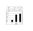
試験結果を表1に示す。比摩耗量は摩耗体積を摺動距離と荷重で除した値であり、形成された摩耗痕の短径、相手材の形状寸法(φ40mmおよびR60mm)から摩耗体積を算出した。なお、表1は、実験例1の摩耗量および摩擦係数を1.000とした場合の実験例2の摩耗量および摩擦係数を示した。
試験結果を表1に示す。比摩耗量は摩耗体積を摺動距離と荷重で除した値であり、形成された摩耗痕の短径、相手材の形状寸法(φ40mmおよびR60mm)から摩耗体積を算出した。なお、表1は、実験例1の摩耗量および摩擦係数を1.000とした場合の実験例2の摩耗量および摩擦係数を示した。

表1に示すように、電子線照射しなかった実験例1に比較して、実験例2は、摩擦係数は増加するものの優れた比摩耗量を示した。
次に本発明に用いる摺動部材の第二のフッ素樹脂層の表面層近傍が架橋構造を有していることについて説明する。一般に、フッ素系樹脂、特にポリテトラフルオロエチレン樹脂は化学的に非常に安定で、有機溶媒などに対しても極めて安定であるため、分子構造あるいは分子量などを同定することは困難である。しかしながら19F Magic angle Spinning(MAS)核磁気共鳴(NMR)法(High speed magic angle nuclear magnetic resonance)による測定ならびに解析により、本発明の摺動部材の架橋構造を同定することが可能となる。
測定は、日本電子株式会社製NMR装置JNM-ECX400を用いて、好適な測定核種(19F)、共鳴周波数(376.2MHz)、MAS(Magic Angle Spinning)回転数(15および12kHz)、サンプル量(4mm固体NMR管に約70μL)、待ち時間(recycle delay time)(10秒)ならびに測定温度(約24℃)で行なった。結果を図4~図7に示す。図4は実験例1の表面層のNMR、図5は実験例2のNMRチャートの拡大図をそれぞれ表す。また、実験例3の表面層のNMRを図6に表す。図4~図6において上段はMAS回転数15kHz、下段はMAS回転数12kHzをそれぞれ表す。図7は架橋に伴い強度が増加する-82ppmでのシグナル強度を主シグナルである-122ppmでのシグナル強度で規格化し、グラフにしたものである。図5において上段は測定値、下段はグラフを表す。このシグナル強度比が高いほど架橋度が進行しているものと考えられる。
放射線照射を行なっていない第二のフッ素樹脂層(実験例1、0kGy)を上記の条件で測定すると、MAS回転数15kHzにおいて、-82ppm、-122ppm、-162ppmのシグナルが観測された(図4上段)。また、MAS回転数12kHzにおいて、同じく、-58ppm、-82ppm、-90ppm、-122ppm、-154ppm、-186ppmのシグナルが観測された(図4下段)。-122ppmは-CF2-CF2-結合におけるF原子のシグナルであり、-82ppmは-CF2-CF3結合における-CF3のF原子のシグナルであることが知られている。このことから、MAS回転数15kHzにおける-82ppmおよび-162ppm、MAS回転数12kHzにおける-58ppm、-90ppm、-154ppm、-186ppmのシグナルはスピニングサイドバンド(Spinning Side Band:SSB)である。なお、-122ppm~-130ppmの領域で-122ppmのシグナルに隠れてブロードになっているシグナルが観測されている。このシグナルは-126ppmに観測されるはずの-CF2-CF3結合における-CF2-のF原子のシグナルである。従って、放射線照射を行なっていない未架橋の第二のフッ素樹脂層は-CF2-CF2-結合に帰属する-122ppm、-CF2-CF3に帰属する-82ppmおよび-126ppmのシグナルを有するNMRチャートで表される。
500kGyの線量の放射線を照射した第二のフッ素樹脂の表面層(実験例2、500kGy)の固体19F MAS NMRを未架橋の第二のフッ素樹脂層と同じ条件で測定すると、スピニングサイドバンドを除いて、-68ppm、-70ppm、-80ppm、-82ppm、-109ppm、-112ppm、-122ppm、-126ppm、-152ppm、および-186ppmのシグナルが観測された(図5上段および図5下段)。-68ppm、-70ppm、-80ppm、-109ppm、-112ppm、-152ppm、および-186ppmのシグナルが放射線照射により新たに出現し、-82ppmのシグナルはその強度が未照射より増加していた。
1000kGyの線量の放射線を照射した第二のフッ素樹脂の表面層(実験例3、1000kGy)の固体19F MAS NMRを未架橋の第二のフッ素樹脂層と同じ条件で測定すると、スピニングサイドバンドを除いて、-68ppm、-70ppm、-77ppm、-80ppm、-82ppm、-109ppm、-112ppm、-122ppm、-126ppm、-152ppm、および-186ppmのシグナルが観測された(図6上段および図6下段)。-68ppm、-70ppm、-77ppm、-80ppm、-109ppm、-112ppm、-152ppm、および-186ppmのシグナルが放射線照射により新たに出現し、-82ppmのシグナルはそのシグナル強度が500kGy照射時より増加していた。
上記シグナルは、帰属するF原子を下線で表せば、例えば-70ppmは=CF-CF
3、-109ppmは-CF
2-CF(CF3)-CF
2-、-152ppmは=CF-CF=、-186ppmは≡CFに帰属されることが知られている(Beate Fuchs and Ulrich Scheler., Branching and Cross-Linking in Radiation-Modified Poly(tetrafluoroethylene):A Solid-State NMR Investigation.Macromolecules,33,120-124.2000年)。
これらのシグナルは化学的に非等価なフッ素原子の存在を示すと同時に第二のフッ素樹脂の表面層が架橋による三次元構造を形成していることを示す。また、上記文献によれば、観測されるシグナルの強度は照射線量500kGyよりも照射線量1000kGyの方が強くなり、少なくとも照射線量3000kGyまでは、照射線量の増加に伴ってシグナルが強くなることが知られている。なお、上記文献に記載されていないシグナルについては、放射線の照射条件の違いにより第二のフッ素樹脂層の構造が異なっていることが考えられるが、架橋構造が形成されていることは、=CF-CF
3、-CF
2-CF(CF3)-CF
2-、=CF-CF=、≡CF等の構造が存在することから明白である。
図7に示すように、規格化シグナル強度比は、照射線量が増加するに従って増加している。照射線量が500kGyで明らかに架橋構造が出現していることが分かる。
上記実験例に用いた第二のフッ素樹脂層を形成する水系塗布液を90℃の恒温槽内で30分程度の乾燥条件により塗布後乾燥後、空気中で380℃の加熱炉内で30分間焼成して、厚さ4μmの未架橋フッ素樹脂被膜を作製した。このフィルムを5枚密接して積層し、一方の面から、上記第2の実験条件にて電子線照射を行なった。照射後、フッ素樹脂被膜を分離して、それぞれのフィルムについて、日本電子株式会社製NMR装置JNM-ECX400を用いて、上記実験例に従いNMR測定を行なった。測定の結果、照射面から照射と反対側の面に存在するフィルムに向かって架橋に伴うシグナル強度が低下し、傾斜構造を有していることが分かった。
[上記(2)の態様からなる摺動層]
摺動層の断面図を図3(b)に示す。摺動層12は、金属材13の表面に形成された下地層14と、この下地層14の表面に形成された架橋フッ素樹脂層15とからなる。架橋フッ素樹脂層15は摺動層表面から基材面まで架橋された架橋フッ素樹脂層である。
摺動層の断面図を図3(b)に示す。摺動層12は、金属材13の表面に形成された下地層14と、この下地層14の表面に形成された架橋フッ素樹脂層15とからなる。架橋フッ素樹脂層15は摺動層表面から基材面まで架橋された架橋フッ素樹脂層である。
金属材の表面に耐熱性樹脂および第一のフッ素樹脂を含む下地層と、この下地層表面に第二のフッ素樹脂層とを有し、上記耐熱性樹脂は、炭素原子と共に、酸素原子、窒素原子および硫黄原子の少なくとも1つの原子を高分子構造の少なくとも主鎖に含む樹脂である点は上記(1)の態様からなる摺動層と同じである。電子線照射装置として株式会社NHVコーポレーション社製EPS-3000を用い、加速電圧を1.16MVにする以外は上記(1)の態様と同一の方法で架橋フッ素樹脂層を得た。この摺動層の表面および基材側の面の固体19F MAS NMRを測定したところ、第二のフッ素樹脂層の表面から基材面まで架橋していることが分かった。
[上記(3)の態様からなる摺動層]
摺動層の断面図を図8(a)に示す。摺動層12は、金属材13の表面に形成された架橋フッ素樹脂層15からなる。架橋フッ素樹脂層15は金属基材と接していない一の面15aおよびその近傍に存在するフッ素樹脂が三次元構造からなる架橋構造を有し、該フッ素樹脂層の、金属基材と接している他の面14aおよびその近傍14に存在するフッ素樹脂が未架橋構造を有し、該一の面と該他の面との間に存在するフッ素樹脂の三次元構造の含率が連続的に変化している架橋フッ素樹脂層である。
摺動層の断面図を図8(a)に示す。摺動層12は、金属材13の表面に形成された架橋フッ素樹脂層15からなる。架橋フッ素樹脂層15は金属基材と接していない一の面15aおよびその近傍に存在するフッ素樹脂が三次元構造からなる架橋構造を有し、該フッ素樹脂層の、金属基材と接している他の面14aおよびその近傍14に存在するフッ素樹脂が未架橋構造を有し、該一の面と該他の面との間に存在するフッ素樹脂の三次元構造の含率が連続的に変化している架橋フッ素樹脂層である。
下地層を用いない以外は上記(1)の態様からなる架橋フッ素樹脂の製造工程と同様にして金属材13の表面に摺動層12を形成した。この摺動層の表面15aの固体19F MAS NMRを測定したところ、摺動層表面が架橋していることが分かった。
[上記(4)の態様からなる摺動層]
摺動層の断面図を図8(b)に示す。摺動層12は、上記(2)の態様からなる摺動層の形成と同様に、電子線照射装置として株式会社NHVコーポレーション社製EPS-3000を用い、加速電圧を1.16MVにして形成した。摺動層12は、金属材13の表面に形成された架橋フッ素樹脂層15からなる。架橋フッ素樹脂層15は金属基材面から摺動層表面まで三次元構造からなる架橋構造を有している。この摺動層の表面の面の固体19F MAS NMRを測定したところ、摺動層表面が架橋していることが分かった。
摺動層の断面図を図8(b)に示す。摺動層12は、上記(2)の態様からなる摺動層の形成と同様に、電子線照射装置として株式会社NHVコーポレーション社製EPS-3000を用い、加速電圧を1.16MVにして形成した。摺動層12は、金属材13の表面に形成された架橋フッ素樹脂層15からなる。架橋フッ素樹脂層15は金属基材面から摺動層表面まで三次元構造からなる架橋構造を有している。この摺動層の表面の面の固体19F MAS NMRを測定したところ、摺動層表面が架橋していることが分かった。
[上記(5)の態様からなる摺動層]
摺動層はフッ素樹脂と溶媒に可溶する耐熱性樹脂との混合樹脂組成物であり、初期混合物の配合割合に比較して、耐熱性樹脂の含有割合が摺動層の表面側よりも軸受の基材側に多く、また、フッ素樹脂の含有割合が基材側よりも摺動層の表面側に多くそれぞれ含まれている。また、フッ素樹脂は、摺動層の表面およびその近傍が架橋された三次元構造を、摺動層の基材側面およびその近傍が未架橋の二次元構造をそれぞれ有している。
摺動層の断面図を図9(a)、(b)に示す。図9(a)は摺動層の表面およびその近傍領域のフッ素樹脂が三次元構造を有する例であり、図9(b)はフッ素樹脂が三次元構造から二次元構造へ連続的に変化する傾斜構造を有する例である。
図9(a)に示すように、フォイル軸受の表面に形成される摺動層12は、金属材13の表面に形成されている。摺動層12は、フッ素樹脂と耐熱性樹脂との混合樹脂組成物であり、基材層側領域14に耐熱性樹脂が、摺動層の表面側領域15にフッ素樹脂が、混合樹脂組成物の全体の配合割合よりもそれぞれ多量に含まれている。また、フッ素樹脂は、摺動層の表面およびその近傍領域に三次元構造を有し、基材層側は未架橋の二次元構造を有している。
図9(b)はフッ素樹脂が三次元構造から二次元構造へ連続的に変化する傾斜構造を有する例である。軸受断面11に設けられる摺動層12は、フッ素樹脂と耐熱性樹脂との混合樹脂組成物であり、基材層側領域14に耐熱性樹脂が、摺動層の表面側領域15にフッ素樹脂が、混合樹脂組成物の全体の配合割合よりもそれぞれ多量に含まれている。また、摺動層12の層厚さtの表面15a側から基材側14aの面に向かってフッ素樹脂の高分子構造が三次元構造から二次元構造へ連続的に変化する傾斜構造を有している。
フッ素樹脂は、基材の表面に塗膜を形成できる分散液、または溶液であれば使用できる。分散液としては水系塗布液に粒子状に分散できるフッ素樹脂が好ましい。フッ素樹脂としては、PTFE樹脂、PFA共重合体、FEP共重合体、エチレン・テトラフルオロエチレン共重合体等が挙げられる。これらの樹脂は単独でも混合物としても使用できる。また、これらの中で、耐熱性および摺動性に優れるPTFEが好ましい。
摺動層を構成する耐熱性樹脂は、基材表面に分散液および/または溶液を塗布・乾燥後、焼成して摺動層を形成する時に熱分解しない樹脂である。ここで熱分解しないとは、混合樹脂を焼成する温度および時間内において、熱分解を開始しない樹脂である。熱分解の開始は、例えばTGなどの熱分解装置により測定できる。
耐熱性樹脂は、非プロトン極性溶媒に溶解する芳香族系樹脂であることが好ましい。耐熱および耐放射線性に優れると共に、塗膜形成時に耐熱樹脂が液状となり、表面エネルギーの小さいフッ素樹脂が摺動層表面側に分布し、フッ素樹脂よりも表面エネルギーの大きな耐熱性樹脂が基材側に分布することで、表面の潤滑性に優れ、基材との密着性に優れた摺動層が形成される。表面側のフッ素樹脂層は架橋されることで、更に摺動特性が向上する。
非プロトン極性溶媒としては、N-メチル-2-ピロリドン、N,N-ジメチルホルムアミド、N,N-ジエチルホルムアミド、N,N-ジメチルアセトアミド、ジメチルスルホキシド等が挙げられる。これらの中で沸点が202℃であり、水と任意の割合で混合するN-メチル-2-ピロリドンが好ましい。
上記非プロトン極性溶媒に溶解する芳香族系樹脂としては、芳香族ポリアミドイミド樹脂、溶媒可溶性芳香族ポリイミド樹脂、溶媒可溶性芳香族ポリアミド樹脂、芳香族ポリベンゾイミダゾール樹脂、芳香族ポリベンゾオキサゾール樹脂等が挙げられ、これらは単独でも混合しても使用できる。これらの中で、溶媒可溶性および被膜の耐熱性に優れている芳香族ポリアミドイミド樹脂が好ましい。
芳香族ポリアミドイミド樹脂は、分子内に芳香環とイミド結合とアミド結合とを有する樹脂である。このような芳香族系ポリアミドイミド樹脂は、芳香族第一級ジアミン、たとえばジフェニルメタンジアミンと芳香族三塩基酸無水物、たとえばトリメリット酸無水物のモノまたはジアシルハライド誘導体から製造されるポリアミドイミド、芳香族三塩基酸無水物と芳香族ジイソシアネート化合物、たとえばジフェニルメタンジイソシアネートとから製造されるポリアミドイミドなどがあり、さらに、アミド結合に比べてイミド結合の比率を大きくしたポリアミドイミドとして、芳香族、脂肪族または脂環族ジイソシアネート化合物と芳香族四塩基酸二無水物および芳香族三塩基酸無水物とから製造されるポリアミドイミド等があり、いずれのポリアミドイミド樹脂であっても使用することができる。
上記芳香族系樹脂に併用できる樹脂としては、エポキシ樹脂、ポリエステル樹脂、エーテルイミド樹脂、ポリエーテルスルホン樹脂、ポリスルホン樹脂、ポリエーテルエーテルケトン樹脂、シリコーン樹脂等が挙げられる。また、フッ素樹脂が塗膜形成時の収縮を防ぐウレタン樹脂、アクリル樹脂を併用することができる。
摺動層を形成する混合樹脂組成物におけるフッ素樹脂と耐熱性樹脂との混合割合は、フッ素樹脂および耐熱性樹脂の合計を100体積部として、耐熱性樹脂の割合が1~50体積部、好ましくは5~30体積部、より好ましくは5~10体積部である。耐熱性樹脂の割合が1体積部未満であると、金属基材とフッ素樹脂との線膨張係数の差が大きくなり、摺動層に引張り応力がかかり、フォイル表面に製膜した場合、ソリや剥離が生じ、軸受の場合、表面にひび割れが生じやすくなる。また、耐熱性樹脂の割合が50体積部を超えるとフッ素樹脂の割合が少なくなり、摺動性が不十分となる。
上記フッ素樹脂と上記耐熱性樹脂とを混合した水系塗布液を作製して、この塗布液を基板上に塗布・乾燥後、焼成して、未架橋前の混合樹脂組成物被膜が作製できる。
水系塗布液は、主溶媒としての水にフッ素樹脂および耐熱樹脂の微粒子を分散させることで得られる。溶媒としては耐熱性樹脂を溶解させると共に、水と任意の割合で混合するN-メチル-2-ピロリドンなどの非プロトン系極性溶剤を配合することが好ましい。また、水系塗布液には、ポリオキシエチレンアルキルエーテルなどの非イオン界面活性剤、カーボンブラックなどの無機顔料、主溶媒としての水が配合される。また、消泡剤、乾燥剤、増粘剤、レベリング剤、ハジキ防止剤などを配合できる。
水系塗布液は、主溶媒としての水にフッ素樹脂および耐熱樹脂の微粒子を分散させることで得られる。溶媒としては耐熱性樹脂を溶解させると共に、水と任意の割合で混合するN-メチル-2-ピロリドンなどの非プロトン系極性溶剤を配合することが好ましい。また、水系塗布液には、ポリオキシエチレンアルキルエーテルなどの非イオン界面活性剤、カーボンブラックなどの無機顔料、主溶媒としての水が配合される。また、消泡剤、乾燥剤、増粘剤、レベリング剤、ハジキ防止剤などを配合できる。
未架橋前の混合樹脂組成物被膜は、上記耐熱性樹脂を非プロトン極性溶媒に溶解または分散させた溶液に、フッ素樹脂の微粒子を分散させた分散型塗布液を用いて、塗布・乾燥後、焼成して製造することができる。その後、下地層を用いない以外は上記(1)の態様からなる架橋フッ素樹脂の製造工程と同様にして金属材13の表面に架橋フッ素樹脂からなる摺動層12を形成した。この摺動層の表面15aの固体19F MAS NMRを測定したところ、摺動層表面が架橋していることが分かった。
[上記(6)の態様からなる摺動層]
摺動層の断面図を図9(c)に示す。摺動層12はフッ素樹脂と耐熱性樹脂との混合樹脂組成物であり、初期混合物の配合割合に比較して、耐熱性樹脂の含有割合が摺動層の表面側よりも軸受の基材側に多く、また、フッ素樹脂の含有割合が基材側よりも摺動層の表面側に多くそれぞれ含まれている。また、フッ素樹脂は、上記(2)の態様からなる摺動層の形成と同様に、電子線照射装置として株式会社NHVコーポレーション社製EPS-3000を用い、加速電圧を1.16MVにして架橋し、摺動層の表面から基材側近傍まで架橋している。この摺動層全体の固体19F MAS NMRを測定したところ、摺動層が架橋していることが分かった。
摺動層の断面図を図9(c)に示す。摺動層12はフッ素樹脂と耐熱性樹脂との混合樹脂組成物であり、初期混合物の配合割合に比較して、耐熱性樹脂の含有割合が摺動層の表面側よりも軸受の基材側に多く、また、フッ素樹脂の含有割合が基材側よりも摺動層の表面側に多くそれぞれ含まれている。また、フッ素樹脂は、上記(2)の態様からなる摺動層の形成と同様に、電子線照射装置として株式会社NHVコーポレーション社製EPS-3000を用い、加速電圧を1.16MVにして架橋し、摺動層の表面から基材側近傍まで架橋している。この摺動層全体の固体19F MAS NMRを測定したところ、摺動層が架橋していることが分かった。
実施例1、比較例1、比較例2
図2(a)に示すリーフフォイル軸受のフォイルの表面に上記実験例2の材料を用いて厚さ50μmの架橋PTFEからなる摺動層を形成し実施例1とした。また、上記実験例1の材料を用いて厚さ50μmの未架橋架橋PTFEからなる摺動層を形成し比較例1とした。図2(a)に示すリーフフォイル軸受のフォイルの表面に公知の方法により厚さ2μmのDLC膜を形成し、比較例2とした。
これらのリーフフォイル軸受を用いて、軸の回転による浮上-停止を1サイクルとし、サイクル回数を重ねた際の摺動に対する被膜の耐久性を確認した。結果を表2に記す。
図2(a)に示すリーフフォイル軸受のフォイルの表面に上記実験例2の材料を用いて厚さ50μmの架橋PTFEからなる摺動層を形成し実施例1とした。また、上記実験例1の材料を用いて厚さ50μmの未架橋架橋PTFEからなる摺動層を形成し比較例1とした。図2(a)に示すリーフフォイル軸受のフォイルの表面に公知の方法により厚さ2μmのDLC膜を形成し、比較例2とした。
これらのリーフフォイル軸受を用いて、軸の回転による浮上-停止を1サイクルとし、サイクル回数を重ねた際の摺動に対する被膜の耐久性を確認した。結果を表2に記す。

表2に示すように、比較例2のDLC被膜を形成したリーフフォイル軸受と比較して、架橋PTFE被膜を形成した実施例1のリーフフォイル軸受は、耐久性能に優れ、サイクル回数25000サイクル後も被膜が残る結果となった。なお、50μmの厚さの被膜を施すことによるフォイルの可撓性への影響も見られなかった。PTFEの架橋の有無について比較例1と比較すると、放射線照射による架橋処理により、耐久性能の向上が確認できる。
本発明は、フォイル軸受の摺動面の摩擦摩耗耐久性能が向上すると共に始動時のトルクを低下できるので、ラジアルフォイル軸受、スラストフォイル軸受等全てのフォイル軸受に使用できる。
1 フォイル軸受
2 軸
3 トップフォイル
4 バックフォイル
5 フォイルホルダ
6 摺動層
7 リーフフォイル軸受
8 リーフ型のフォイル
9 フォイルホルダ
10 バンプフォイル軸受
11 バックフォイル
12 摺動層
13 金属材
14 下地層
15 架橋フッ素樹脂層
2 軸
3 トップフォイル
4 バックフォイル
5 フォイルホルダ
6 摺動層
7 リーフフォイル軸受
8 リーフ型のフォイル
9 フォイルホルダ
10 バンプフォイル軸受
11 バックフォイル
12 摺動層
13 金属材
14 下地層
15 架橋フッ素樹脂層
Claims (8)
- 可撓性を有する薄いフォイルで軸受面を構成し、このフォイルが弾性変形可能となるように支持部を備え、回転側部材の回転に伴って前記フォイルに設けた第1軸受面と、これに対向する前記回転側部材の第2軸受面との間の軸受隙間に流体膜が形成され、その圧力で前記回転側部材が支持されるフォイル軸受であって、
前記フォイルの表面および裏面の少なくとも1つの面に摺動層を有し、
前記第1軸受面および前記第2軸受面の少なくとも1つの軸受面が摺動層を有し、前記摺動層は少なくとも表面およびその近傍が架橋フッ素樹脂層を有することを特徴とするフォイル軸受。 - 前記摺動層は、前記軸受面に耐熱性樹脂および第一のフッ素樹脂を含む下地層と、この下地層表面に第二のフッ素樹脂層とを有し、
前記耐熱性樹脂は、炭素原子と共に、酸素原子、窒素原子および硫黄原子の少なくとも1つの原子を高分子構造の少なくとも主鎖に含む樹脂であり、
前記第二のフッ素樹脂層は摺動層表面およびその近傍が架橋されてなる架橋フッ素樹脂層であることを特徴とする請求項1記載のフォイル軸受。 - 前記摺動層は、前記軸受面に耐熱性樹脂および第一のフッ素樹脂を含む下地層と、この下地層表面に第二のフッ素樹脂層とを有し、
前記耐熱性樹脂は、炭素原子と共に、酸素原子、窒素原子および硫黄原子の少なくとも1つの原子を高分子構造の少なくとも主鎖に含む樹脂であり、
前記第一のフッ素樹脂および前記第二のフッ素樹脂層が摺動層表面から基材面まで架橋された架橋フッ素樹脂層であることを特徴とする請求項1記載のフォイル軸受。 - 前記摺動層はフッ素樹脂層であり、このフッ素樹脂層は摺動層表面およびその近傍に存在するフッ素樹脂が三次元構造からなる架橋構造を有し、前記基材と接している面およびその近傍に存在するフッ素樹脂が二次元構造からなる未架橋構造を有し、前記摺動層表面から前記基材と接している面に向かって前記三次元構造の含率が連続的に少なくなることを特徴とする請求項1記載のフォイル軸受。
- 前記摺動層はフッ素樹脂層であり、前記摺動層は摺動層表面から前記基材と接している面まで架橋された架橋フッ素樹脂層であることを特徴とする請求項1記載のフォイル軸受。
- 前記摺動層は樹脂組成物からなる摺動層であり、前記樹脂組成物はフッ素樹脂と溶媒に可溶する耐熱性樹脂との混合樹脂組成物であり、
前記耐熱性樹脂の含有割合は、前記混合樹脂組成物全体の配合割合に対して、前記摺動層の表面側よりも前記基材と接している面側に多く含まれ、
前記フッ素樹脂の含有割合は、前記混合樹脂組成物全体の配合割合に対して、前記基材と接している面側よりも前記摺動層の表面側に多く含まれ、
前記フッ素樹脂は、前記摺動層の表面およびその近傍が架橋された三次元構造を、前記基材と接している面およびその近傍が未架橋の二次元構造をそれぞれ有する架橋フッ素樹脂層であることを特徴とする請求項1記載のフォイル軸受。 - 前記摺動層は樹脂組成物からなる摺動層であり、前記樹脂組成物はフッ素樹脂と溶媒に可溶する耐熱性樹脂との混合樹脂組成物であり、
前記耐熱性樹脂の含有割合は、前記混合樹脂組成物全体の配合割合に対して、前記摺動層の表面側よりも前記基材と接している面側に多く含まれ、
前記フッ素樹脂の含有割合は、前記混合樹脂組成物全体の配合割合に対して、前記基材と接している面側よりも前記摺動層の表面側に多く含まれ、
前記フッ素樹脂は、前記摺動層表面から前記基材と接している面まで架橋された架橋フッ素樹脂層であることを特徴とする請求項1記載のフォイル軸受。 - 前記摺動層からなる軸受面の相手面となる摺動部材の表面粗さがRa 0.8μm以下であることを特徴とする請求項1記載のフォイル軸受。
Applications Claiming Priority (2)
| Application Number | Priority Date | Filing Date | Title |
|---|---|---|---|
| JP2015-153738 | 2015-08-03 | ||
| JP2015153738A JP6591820B2 (ja) | 2015-08-03 | 2015-08-03 | フォイル軸受 |
Publications (1)
| Publication Number | Publication Date |
|---|---|
| WO2017022795A1 true WO2017022795A1 (ja) | 2017-02-09 |
Family
ID=57943088
Family Applications (1)
| Application Number | Title | Priority Date | Filing Date |
|---|---|---|---|
| PCT/JP2016/072799 WO2017022795A1 (ja) | 2015-08-03 | 2016-08-03 | フォイル軸受 |
Country Status (2)
| Country | Link |
|---|---|
| JP (1) | JP6591820B2 (ja) |
| WO (1) | WO2017022795A1 (ja) |
Cited By (4)
| Publication number | Priority date | Publication date | Assignee | Title |
|---|---|---|---|---|
| WO2018164154A1 (ja) * | 2017-03-10 | 2018-09-13 | Ntn株式会社 | フォイル軸受 |
| WO2019124393A1 (ja) * | 2017-12-19 | 2019-06-27 | Ntn株式会社 | フォイル軸受、フォイル軸受ユニット、ターボ機械、フォイル軸受の製造方法 |
| JP2019108968A (ja) * | 2017-12-19 | 2019-07-04 | Ntn株式会社 | フォイル軸受、フォイル軸受ユニット、ターボ機械、フォイル軸受の製造方法 |
| WO2020099226A1 (de) * | 2018-11-14 | 2020-05-22 | Robert Bosch Gmbh | Luftlager |
Families Citing this family (1)
| Publication number | Priority date | Publication date | Assignee | Title |
|---|---|---|---|---|
| CN110701188B (zh) * | 2019-10-21 | 2020-09-29 | 北京航空航天大学 | 一种用于磁轴承的柔性簧片轴向保护轴承 |
Citations (5)
| Publication number | Priority date | Publication date | Assignee | Title |
|---|---|---|---|---|
| JP2003262222A (ja) * | 2002-03-08 | 2003-09-19 | Ntn Corp | フォイル軸受 |
| JP2005030460A (ja) * | 2003-07-09 | 2005-02-03 | Honda Motor Co Ltd | フォイル式流体軸受、フォイル式流体軸受の製造方法およびフォイル式流体軸受の寸法測定装置 |
| US20080057223A1 (en) * | 2006-08-29 | 2008-03-06 | Yong Bok Lee | Medium temperature coating material for high speed turbomachinery and method of coating same |
| JP2013503306A (ja) * | 2009-08-28 | 2013-01-31 | サン−ゴバン パフォーマンス プラスチックス パンプス ゲゼルシャフト ミット ベシュレンクテル ハフツング | 耐食性ブッシング |
| JP2013539846A (ja) * | 2010-09-28 | 2013-10-28 | サン−ゴバン パフォーマンス プラスティックス コーポレイション | ブッシュのためのキャストフルオロポリマーフィルム |
Family Cites Families (1)
| Publication number | Priority date | Publication date | Assignee | Title |
|---|---|---|---|---|
| JP4015388B2 (ja) * | 2001-08-20 | 2007-11-28 | 三菱重工業株式会社 | フォイルガス軸受 |
-
2015
- 2015-08-03 JP JP2015153738A patent/JP6591820B2/ja not_active Expired - Fee Related
-
2016
- 2016-08-03 WO PCT/JP2016/072799 patent/WO2017022795A1/ja active Application Filing
Patent Citations (5)
| Publication number | Priority date | Publication date | Assignee | Title |
|---|---|---|---|---|
| JP2003262222A (ja) * | 2002-03-08 | 2003-09-19 | Ntn Corp | フォイル軸受 |
| JP2005030460A (ja) * | 2003-07-09 | 2005-02-03 | Honda Motor Co Ltd | フォイル式流体軸受、フォイル式流体軸受の製造方法およびフォイル式流体軸受の寸法測定装置 |
| US20080057223A1 (en) * | 2006-08-29 | 2008-03-06 | Yong Bok Lee | Medium temperature coating material for high speed turbomachinery and method of coating same |
| JP2013503306A (ja) * | 2009-08-28 | 2013-01-31 | サン−ゴバン パフォーマンス プラスチックス パンプス ゲゼルシャフト ミット ベシュレンクテル ハフツング | 耐食性ブッシング |
| JP2013539846A (ja) * | 2010-09-28 | 2013-10-28 | サン−ゴバン パフォーマンス プラスティックス コーポレイション | ブッシュのためのキャストフルオロポリマーフィルム |
Cited By (5)
| Publication number | Priority date | Publication date | Assignee | Title |
|---|---|---|---|---|
| WO2018164154A1 (ja) * | 2017-03-10 | 2018-09-13 | Ntn株式会社 | フォイル軸受 |
| WO2019124393A1 (ja) * | 2017-12-19 | 2019-06-27 | Ntn株式会社 | フォイル軸受、フォイル軸受ユニット、ターボ機械、フォイル軸受の製造方法 |
| JP2019108968A (ja) * | 2017-12-19 | 2019-07-04 | Ntn株式会社 | フォイル軸受、フォイル軸受ユニット、ターボ機械、フォイル軸受の製造方法 |
| JP7065715B2 (ja) | 2017-12-19 | 2022-05-12 | Ntn株式会社 | フォイル軸受、フォイル軸受ユニット、ターボ機械、フォイル軸受の製造方法 |
| WO2020099226A1 (de) * | 2018-11-14 | 2020-05-22 | Robert Bosch Gmbh | Luftlager |
Also Published As
| Publication number | Publication date |
|---|---|
| JP2017032094A (ja) | 2017-02-09 |
| JP6591820B2 (ja) | 2019-10-16 |
Similar Documents
| Publication | Publication Date | Title |
|---|---|---|
| WO2017022795A1 (ja) | フォイル軸受 | |
| WO2017022803A1 (ja) | 摺動部材、転がり軸受および保持器 | |
| WO2015115655A1 (ja) | 摺動部材、転がり軸受および保持器 | |
| WO2012043336A1 (ja) | 斜板式コンプレッサの斜板および斜板式コンプレッサ | |
| JP2014046673A (ja) | 摺動部材 | |
| JPWO2006080527A1 (ja) | 薄肉軸受 | |
| JP2014240614A (ja) | 容積式ポンプ | |
| JP6457285B2 (ja) | 転がり軸受用保持器および転がり軸受 | |
| JP2017032142A (ja) | 摺動部材、転がり軸受および保持器 | |
| JP6517523B2 (ja) | 摺動部材、転がり軸受および保持器 | |
| JP2018059629A (ja) | 転がり軸受用保持器および転がり軸受 | |
| JP2007002912A (ja) | 転がり軸受 | |
| WO2017022801A1 (ja) | 摺動部材、転がり軸受および保持器 | |
| JP2017032143A (ja) | 摺動部材、転がり軸受および保持器 | |
| WO2017022794A1 (ja) | 転がり軸受用保持器および転がり軸受 | |
| WO2017164399A1 (ja) | 転がり軸受用保持器および転がり軸受 | |
| WO2018062407A1 (ja) | 転がり軸受用保持器および転がり軸受 | |
| JP6577193B2 (ja) | 転がり軸受用保持器および転がり軸受 | |
| JP6517562B2 (ja) | 主電動機用軸受 | |
| JP2020051444A (ja) | 駆動車輪用軸受装置 | |
| JP6855974B2 (ja) | 転がり軸受及びその製造方法 | |
| JP2020051506A (ja) | 転がり軸受用保持器および転がり軸受 | |
| JP2020051439A (ja) | 摺動部材、転がり軸受および保持器 | |
| JP2018059628A (ja) | 転がり軸受用保持器および転がり軸受 | |
| JP2017032092A (ja) | 転がり軸受用保持器および転がり軸受 |
Legal Events
| Date | Code | Title | Description |
|---|---|---|---|
| 121 | Ep: the epo has been informed by wipo that ep was designated in this application |
Ref document number: 16833074 Country of ref document: EP Kind code of ref document: A1 |
|
| NENP | Non-entry into the national phase |
Ref country code: DE |
|
| 122 | Ep: pct application non-entry in european phase |
Ref document number: 16833074 Country of ref document: EP Kind code of ref document: A1 |