WO2017018071A1 - セグメント - Google Patents
セグメント Download PDFInfo
- Publication number
- WO2017018071A1 WO2017018071A1 PCT/JP2016/067174 JP2016067174W WO2017018071A1 WO 2017018071 A1 WO2017018071 A1 WO 2017018071A1 JP 2016067174 W JP2016067174 W JP 2016067174W WO 2017018071 A1 WO2017018071 A1 WO 2017018071A1
- Authority
- WO
- WIPO (PCT)
- Prior art keywords
- piece
- segment
- ring
- concrete
- plate
- Prior art date
- Legal status (The legal status is an assumption and is not a legal conclusion. Google has not performed a legal analysis and makes no representation as to the accuracy of the status listed.)
- Ceased
Links
Images

Classifications
-
- E—FIXED CONSTRUCTIONS
- E02—HYDRAULIC ENGINEERING; FOUNDATIONS; SOIL SHIFTING
- E02D—FOUNDATIONS; EXCAVATIONS; EMBANKMENTS; UNDERGROUND OR UNDERWATER STRUCTURES
- E02D23/00—Caissons; Construction or placing of caissons
-
- E—FIXED CONSTRUCTIONS
- E21—EARTH OR ROCK DRILLING; MINING
- E21D—SHAFTS; TUNNELS; GALLERIES; LARGE UNDERGROUND CHAMBERS
- E21D11/00—Lining tunnels, galleries or other underground cavities, e.g. large underground chambers; Linings therefor; Making such linings in situ, e.g. by assembling
- E21D11/04—Lining with building materials
-
- E—FIXED CONSTRUCTIONS
- E21—EARTH OR ROCK DRILLING; MINING
- E21D—SHAFTS; TUNNELS; GALLERIES; LARGE UNDERGROUND CHAMBERS
- E21D5/00—Lining shafts; Linings therefor
- E21D5/06—Lining shafts; Linings therefor with iron or steel
- E21D5/10—Lining shafts; Linings therefor with iron or steel in the form of tubbing or of rings composed of profile elements
Definitions
- This invention relates to the segment which comprises a sunk structure.
- a ring body is constructed by connecting a plurality of segments, and a plurality of ring bodies are overlapped in the axial direction to be submerged in the ground.
- the sinking body is known.
- the segment constituting the sinking body includes a curved plate that becomes the wall surface of the sinking structure, a main girder provided at the upper end and lower end of the plate, and a joint provided at the left end and right end of the plate
- the segment which constructs the ring body provided with is known.
- the plate, the main beam, and the joint are all formed in a plate shape (see, for example, Patent Document 1).
- a sinking body in which a press-fit mold frame and a reinforcing bar as an inner frame and a steel structure as an outer frame are arranged from the inside is known. Concrete is driven into the space where the reinforcing bars are arranged between the press-fitting mold and the double frame of the steel structure. Only the steel structure is integrated with the reinforcing bar (see, for example, Patent Document 2).
- an object of the present invention is to provide a segment that can cope with a construction with a large cross section and can suppress a reduction in construction efficiency.
- the present invention is a segment constituting a subsidence structure embedded in the ground, wherein an outer piece forming an outer wall of the subsidence structure and an inner wall of the subsidence structure are formed.
- the piece formed of the concrete is provided with a connecting member for connecting the connecting piece.
- the connecting member is preferably embedded in the concrete in a state where a part of the connecting member is exposed between the outer piece and the inner piece.
- the connecting piece is connected to a portion exposed between the outer piece and the inner piece in the connecting member.
- the connecting member is provided with a distribution bar surrounding the connecting member.
- the connecting member is a steel material embedded in the concrete in a state where a part of the connecting member is exposed between the outer piece and the inner piece, a connecting piece that is provided in the steel material and connects the connecting piece, It is preferable to provide.
- the connecting piece is provided at both ends of the outer piece and the inner piece in the axial direction of the segment.
- the inner piece is made of concrete.
- the outer piece includes a plate forming a wall surface, main girders provided at the upper and lower ends of the plate, and ribs provided between the main girders, and the connecting piece is connected to the ribs. It is preferable that
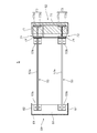
- FIG. 4 is a sectional view of a segment on the IV-IV line in FIG. 2.
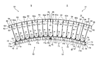
- FIG. 1 is a schematic front view of a part of a submerged structure 100 submerged in the ground, showing an example in which the subsidence structure 100 is applied to a shaft.
- FIG. 2 is a plan view partially showing two of the plurality of segments 5 constituting the double ring 44.
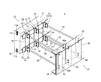
- FIG. 3 is a partial perspective view of the segment 5 as viewed obliquely from the outside in the radial direction toward the inside, and the outer piece 51 is depicted so as to be seen through.
- 4 is a cross-sectional view of the segment 5 shown in FIG. 2 on the IV-IV line.
- the subsidence structure 100 is provided at an excavation start point or an intermediate point of a tunnel T built in the ground by a shield method or the like, and a space S inside the subsidence structure 100 is a shield machine. It becomes a conveyance path and a vent.
- the subsidence structure 100 includes a subsidence body 1 submerged in the ground, a bottom plate part 2 provided at the bottom inside the subsidence body 1, a subsidence anchor 3 used when subsiding the subsidence body 1 into the ground, It has.
- the sinking body 1 is constructed in a cylindrical shape, and is set in the ground so that its axis is along the vertical direction.
- the sinking body 1 is assembled by connecting a plurality of ring bodies 4 having an annular shape in plan view in the axial direction.
- the ring body 4 constituting the set-up body 1 is configured by stacking a blade ring 41, a guide ring 42, a workbench ring 43, and a double ring 44 in the vertical direction.
- the cutting edge ring 41 is a ring body provided at the lowermost end of the settling body 1 and has a cutting edge at the lower end thereof.
- the blade ring 41 has the tooth tip (tip) on the outside.
- a plurality of guide rings 42 are connected to the upper end of the blade ring 41 to guide the sinking of the sinking body 1.
- the work table ring 43 is connected to the upper end of the guide ring 42.
- the worktable ring 43 is formed such that the upper end surface is larger than the lower end surface, and the upper end surface is formed so as to project inside the worktable ring 43.
- the upper end surface of the work table ring 43 is formed to have a size that allows at least the double ring 44 to be placed thereon.
- the double ring 44 is connected to the upper end of the work table ring 43. Above the work table ring 43, a double ring 44 is provided in a plurality of stages.
- the guide ring 42 provided between the blade ring 41 and the work table ring 43 is formed so that the width of the end surface in the axial direction gradually increases from the blade ring 41 toward the work table ring 43. It is more preferable. That is, it is preferable that the upper guide ring 42 is formed such that the width of the upper end surface thereof is closer to the width of the work table ring 43.
- the segments of the upper ring 42 and the segments of the lower ring 41 are shifted in the circumferential direction of the rings 41 and 42 and arranged in a staggered manner. This arrangement also applies to the ring 42 and ring 43, the ring 43 and ring 44, and the rings 44 and 44.
- the ring body 4 is formed by connecting and assembling the segments 5 along the wall surface direction.
- the double ring 44 of the ring body 4 has a plurality of segments 5 connected to each other, and is finally formed into an annular shape.
- FIG. 2 shows a state where two segments 5 are connected.
- the segment 5 of the double ring 44 includes an outer piece 51 that forms the outer wall of the sinking structure 100, an inner piece 52 that forms the inner wall of the sinking structure 100, and a connecting piece that connects the outer piece 51 and the inner piece 52. 53.
- the outer piece 51 is erected on a rectangular plate 61 that is curved and formed in an arc shape that forms the outer wall surface of the double ring 44, and an outer edge along the curvature of the plate 61.
- ribs 64 provided on the inner surface side of the plate 61, and connecting members 65 provided at both ends in the circumferential direction of the plate 61. As shown in FIG.
- the outer piece 51 is installed above the blade ring 41. Specifically, the outer peripheral surfaces of the blade ring 41 and the outer piece 51 are on the same diameter of the sinking body 1. As a result, when the ring body 4 is submerged in the ground, a force is applied above the outer piece 51, so that the pressing force for substituting the ring body 4 is applied to the blade ring 41 via the outer piece 51. It can be transmitted efficiently.
- the material of the outer piece 51 is only required to have resistance against a load when buried in the ground, and is particularly preferably made of steel.
- the main beam 62 and the ribs 64 may both be joined to the plate 61 by welding, or a part thereof may be formed integrally with the plate 61.
- the joint 63 may be joined to the main beam 62 by welding, or a part thereof may be formed integrally with the main beam 62.
- the plate 61 forms the outer wall surface of the double ring 44 and is joined to the end face of the main girder 62 on the outer side in the radial direction of the double ring 44 so as to connect the two main girders 62.
- the main girder 62 is erected on the upper end and lower end of the plate 61.
- Each main girder 62 is formed with a plurality of through holes 62a through which bolts are inserted at predetermined intervals along the longitudinal (extending) direction.
- the through holes 62a of the two main girders 62 are formed so that the through holes 62a penetrate each other along the same axis parallel to the axis of the double ring 44, and the double rings 44 are stacked vertically.
- the through holes 62a of the main girders 62 are formed to face each other.
- the joint 63 is erected at one end on the left side of the main girder 62 between both ends of the two main girders 62.
- the joint 63 on the left side of the adjacent segment 5 is connected to the other end on the right side of the main girder 62 when the segments 5 are connected, so the joint 63 is not provided. Good.
- the rib 64 having both the function of increasing the rigidity of the outer piece 51 and the function of connecting the connecting piece 53 described later is the bending direction (longitudinal direction) of the plate 61.
- the ribs 64 are connected to the inner peripheral surface of the plate 61 by welding or the like at equal intervals in the circumferential direction from the central axis of each through hole 62a of the main girder 62.
- the rib 64 extends between the upper and lower main beams 62, 62 along the axial direction of the segment 5, but is provided with a connecting piece 53 described later. It may be provided corresponding to the position.
- the “axial direction of the segment 5” is the extending direction of the axial line passing through the center of the ring when the segments 5 are connected to form a double ring 44.
- the cross-sectional shape of the rib 64 orthogonal to the axial direction of the segment 5 is substantially L-shaped, the cross-sectional shape is limited as long as the rigidity of the segment 5 is increased and the connection with the connection piece 53 is possible. Not.
- the rib 64 is formed with a through hole for enabling connection with a connection piece 53 described later.
- Bolts are inserted into the through holes on the rib 64 side and the through holes on the connection piece 53 side, and the nuts are fastened to the inserted bolts, whereby the connection piece 53 and the ribs 64 are fastened together.
- the coupling tool 65 is provided at both ends in the circumferential direction of the plate 61 and extends over the width direction (short direction) of the plate 61.
- One end of the coupler 65 is joined to the plate 61 by welding or the like, and the other end is formed in a bowl shape.
- the segments 5 are connected to each other by engaging the connecting tool 65 and the tip of the plates 61 of the adjacent segments 5.
- the segment 5 is connected to the segment 5 adjacent in the circumferential direction by connecting the connector 65 to the flanged other end of the connector 65 of the segment 5 adjacent in the circumferential direction at the other end of the flange shape. Can do.
- the coupling tool 65 may be joined to the plate 61 as a separate member by welding, or may be formed integrally with the plate 61.
- the inner piece 52 includes a segment body 71 having a rectangular shape in plan view, which is curved in an arc shape, which forms the body of the inner piece 52, and a connecting member 72 provided in the segment body 71.
- the segment body 71 is made of concrete.
- the segment main body 71 accommodates a connector 76 described later on both end surfaces on the upper and lower sides in the axial direction passing through the center of the ring when the segments 5 are connected to form a double ring 44.
- a recess 71a is provided.
- the segment body 71 has a plurality of through-holes 71 b that penetrate in the axial direction of the double ring 44 and are arranged in parallel to each other at equal intervals.
- penetrate in the axial direction means that the through-hole 71 b extends from the upper end surface of the segment main body 71 to the lower end surface of the segment main body 71 through the web 73 b of the steel material 73 to be described later. It means to penetrate along the same parallel axis.
- a part of the connecting member 72 is embedded in the segment body 71 and the remaining part is exposed so as to protrude between the outer piece 51 and the inner piece 52, and the connecting piece 53 is connected to the connecting member 72. It is connected to the exposed part. More specifically, the connecting member 72 is exposed to the segment main body 71, that is, the portion embedded in the concrete, and not embedded, and protrudes into the space between the outer piece 51 and the inner piece 52.
- Steel member 73 having a portion (H-shaped steel in the present embodiment, see FIG. 4) and a steel connecting piece 74 provided on the exposed portion of steel member 73 and connected by connecting piece 53 described later. And.
- the steel material 73 is provided at two locations near the upper end and near the lower end in the axial direction of the segment 5, and extends in the circumferential direction of the segment body 71.
- the steel material 73 has two flange portions 73a and 73a and a web 73b that connects the two flange portions 73a and 73a.
- One flange part 73a and a part of the web 73b of the steel material 73 are embedded in the segment body 71, that is, in the concrete, and the other flange part 73a and the remaining part of the web 73b are connected to the outer piece 51 from the segment body 71. It protrudes toward and is exposed.
- the connecting piece 74 is spaced outside the flange portion 73 a where the upper and lower steel members 73 are exposed at a predetermined interval along the bending direction (longitudinal direction) of the segment body 71. It is erected on the surface facing the piece 51. Specifically, the connecting piece 74 is connected to the flange portion 73a by welding or the like. A through hole is formed in the connecting piece 74 for connection with a connecting piece 53 described later, and a bolt is inserted into the through hole on the connecting piece 74 side and the through hole on the connecting piece 53 side. The connecting piece 53 and the connecting piece 74 are fastened to each other by tightening a nut on the bolt.
- the two steel materials 73 and 73 are surrounded by a steel distribution bar 75. More specifically, the distribution bar 75 is a surface facing the outer piece 51 of the flange portions 73a and 73a exposed from the segment body 71 of the steel materials 73 and 73 provided at the upper end portion and the lower end portion, respectively.
- the flange portions 73a and 73a embedded in the segment main body 71 are wound around two steel materials 73 and 73 so as to be in contact with the surface facing the inner peripheral surface of the inner piece 52.
- the portion of the distribution bar 75 that extends along the axial direction of the segment 5 between the upper steel member 73 and the lower steel member 73 and that is exposed from the segment main body 71 and in the segment main body 71.
- the portions to be embedded are connected to each other at a predetermined location so as to fulfill a higher reinforcing function.
- connectors 76 and 76 are provided along a predetermined length in the axial direction of the segment 5. More specifically, the upper connecting member 76 extends from the upper end surface of the segment main body 71 to the surface facing the upper side of the web 73b of the upper steel material 73 on the upper side of the segment main body 71. The connector 76 extends below the segment body 71 from the lower end surface of the segment body 71 to a surface facing the lower side of the web 73b of the lower steel material 73.
- One end of the connector 76 is embedded in the segment main body 71, that is, in the concrete in the recess 71a, and the other end is exposed from the segment main body 71 and is formed in a bowl shape.
- the segments 5 are connected to each other by engaging the connecting tool 76 provided on the segment main body 71 of the adjacent segment 5 with the tips. That is, the segment 5 is connected to the segment 5 adjacent in the circumferential direction by connecting the connector 76 to the flanged other end of the connector 76 of the segment 5 adjacent in the circumferential direction at the other end of the flange shape. be able to.
- the plurality of connecting pieces 53 are provided between the outer piece 51 and the inner piece 52 to connect the two pieces 51, 52, and thereby the shear strength of the segment 5.
- the connecting piece 53 has one end connected to the rib 64 of the outer piece 51 and the other end connected to the connecting member 72 and the connecting piece 74 of the inner piece 52 to connect the outer piece 51 and the inner piece 52. is doing.
- the connecting pieces 53 are provided at the upper end portion and the lower end portion of the segment 5 in the axial direction of the segment 5, respectively.
- the connecting piece 53 includes a steel bar 53a and a steel rectangular plate 53b provided at both ends of the bar 53a.
- the plate material 53b is formed with a through hole that is concentric with the through hole formed in the rib 64 and the connecting piece 74 when connected.
- the plate member 53b, the rib 64, and the connecting piece 74 are connected to each other by inserting bolts into the concentrically aligned through holes and tightening the nuts to the bolts protruding to the opposite side of the insertion side. ing. That is, the connecting piece 53 connects the outer piece 51 and the inner piece 52 by connecting the plate member 53b to the rib 64 of the outer piece 51 and the connecting piece 74 of the inner piece 52 through bolts and nuts. Can do.
- the bottom plate part 2 serves as a foundation of the subsidence structure 100 and prevents underground water from flowing into the subsidence body 1.
- the bottom board part 2 is constructed by, for example, underwater concrete.
- the bottom board part 2 is constructed so that the upper surface thereof is substantially along the horizontal plane.
- the sinking anchor 3 takes a reaction force on the ground when the sinking body 1 is pushed into the ground by applying force to the ring body 4 from above the uppermost ring body 4 in the step of sinking the sinking body 1 into the ground. is there.
- the anchoring anchor 3 is embedded in and fixed to the ground excavated outside and below the settling position of the sinking body 1, and is connected to the fixing part 31. It has a connecting portion 32 that extends to the ground surface along the wall surface and is connected to a stationary portion (such as a base portion) of a sinking device (not shown) that pushes the ring body 4.
- the outer piece 51 and the inner piece 52 are connected by the connecting piece 53, so Also during construction, the outer piece 51 and the inner piece 52 can be separately created and transported to the construction site, and can be connected by the connecting piece 53 at the construction site to form the large segment 5. Thereby, it can respond to the construction in a large section and can suppress the fall of construction efficiency.
- the connecting piece 53 can be used as a shear reinforcement for the segment 5 and can prevent the outer piece 51 and the inner piece 52 from being displaced or inclined from each other.
- the inner piece 52 that faces the space S inside the settling structure 100 is formed of concrete, it is necessary to apply the antirust coating necessary for forming the inner piece 52 of steel to the inner piece 52. Therefore, the work load when creating the segment 5 can be greatly reduced.
- the inner piece 52 formed of concrete is provided with a connecting member 72 having a steel material 73 and a connecting piece 74 for connecting the connecting piece 53, so the inner piece 52, more specifically, While improving the rigidity of the segment main body 71 which consists of concrete, the connection of the connection piece 53 and the inner piece 52 can be made easy.
- the connecting piece 53 when the connecting piece 53 is provided at both ends of the segment 5 in the axial direction thereof, that is, on the upper side and the lower side, respectively, concrete is placed in the space between the outer piece 51 and the inner piece 52. Even if it exists, the relative movement of the outer piece 51 and the inner piece 52 can be suppressed, and the outer piece 51 and the inner piece 52 can always be maintained in the initial positional relationship. Further, since the connecting piece 53 includes the bar 53a and the plate members 53b provided at both ends thereof, the space between the outer piece 51 and the inner piece 52 is not completely partitioned, and the concrete casting is performed. It is possible to spread the concrete over the entire space between the outer piece 51 and the inner piece 52 just by placing the concrete from one place at the time of installation, and also to reduce the weight of the segment 5.
- the rigidity of the segment body 71 can be further increased by having the distribution bars 75 surrounding the steel material 73.
- the present invention is not limited to the above embodiment.
- the double ring 44 is not limited to a circular shape in plan view, and may be formed in an oval shape in plan view (oval shape) or a polygonal shape in plan view.
- the segment 5 may be a segment formed of concrete in the same manner as the inner piece 52 for the outer piece 51. Even when the outer piece 51 is made of concrete, after the settling body 1 is set, the anti-lifting anchor that prevents the settling body 1 from being lifted can be inserted into the through hole 71b.
- the steel 73 can increase the rigidity of the segment main body 71, and partially protrudes from the segment main body 71 into the space between the outer piece 51 and the inner piece 52 so that the connecting piece 53 can be connected. If it is, it is not restricted to H-section steel, You may have another cross-sectional shape. As long as the steel material 73 provides the segment body 71 with a predetermined rigidity, a plurality of steel materials may be provided at predetermined intervals.
- connecting piece 74 of the connecting member 72 is not limited to the case where it is provided on the steel material 73, and may be connected to the distribution bar 75 by welding or the like.
- the connecting piece 53 is not limited to the bar as described above, and may be a steel plate or the like along the axial direction of the segment 5.
- connection between the connection piece 53 and the rib 64 and the connection between the connection piece 53 and the connection piece 74 are not limited to a connection method using bolts and nuts as long as they are connected to each other.
- the connector 76 may be provided across the segment body 71 along the axial direction of the segment 5.
- the recess 71 a is provided along the axial direction of the segment 5 across the end surface on the circumferential side of the segment body 71.
Landscapes
- Engineering & Computer Science (AREA)
- Mining & Mineral Resources (AREA)
- Life Sciences & Earth Sciences (AREA)
- General Life Sciences & Earth Sciences (AREA)
- Structural Engineering (AREA)
- Civil Engineering (AREA)
- Architecture (AREA)
- Geochemistry & Mineralogy (AREA)
- Geology (AREA)
- Paleontology (AREA)
- General Engineering & Computer Science (AREA)
- Mechanical Engineering (AREA)
- Underground Structures, Protecting, Testing And Restoring Foundations (AREA)
- Lining And Supports For Tunnels (AREA)
Applications Claiming Priority (2)
| Application Number | Priority Date | Filing Date | Title |
|---|---|---|---|
| JP2015-147437 | 2015-07-27 | ||
| JP2015147437A JP6545557B2 (ja) | 2015-07-27 | 2015-07-27 | セグメント |
Publications (1)
| Publication Number | Publication Date |
|---|---|
| WO2017018071A1 true WO2017018071A1 (ja) | 2017-02-02 |
Family
ID=57884261
Family Applications (1)
| Application Number | Title | Priority Date | Filing Date |
|---|---|---|---|
| PCT/JP2016/067174 Ceased WO2017018071A1 (ja) | 2015-07-27 | 2016-06-09 | セグメント |
Country Status (2)
| Country | Link |
|---|---|
| JP (1) | JP6545557B2 (enExample) |
| WO (1) | WO2017018071A1 (enExample) |
Citations (6)
| Publication number | Priority date | Publication date | Assignee | Title |
|---|---|---|---|---|
| JPS5125315A (en) * | 1974-08-24 | 1976-03-01 | Chuo Fukuken Konsarutantsu Kk | Pc burotsukunitekochikusuru izutsu mataha senkannokutai |
| JPH09228379A (ja) * | 1996-02-22 | 1997-09-02 | Ishikawajima Constr Materials Co Ltd | 構造物の基礎 |
| JPH09291782A (ja) * | 1996-04-26 | 1997-11-11 | Nippon Steel Corp | 複数のセグメントを用いた柱状構造体 |
| JPH10205271A (ja) * | 1997-01-24 | 1998-08-04 | Kato Kensetsu:Kk | 沈設体用セグメントピースおよび沈設体の構築方法 |
| JP2003328369A (ja) * | 2002-05-09 | 2003-11-19 | Sumitomo Mitsui Construction Co Ltd | プレキャストコンクリート部材、これを用いたケーソンの構築方法及びトンネルの構築方法 |
| JP2004011327A (ja) * | 2002-06-10 | 2004-01-15 | Daiho Constr Co Ltd | ケーソン及びケーソン構築方法 |
-
2015
- 2015-07-27 JP JP2015147437A patent/JP6545557B2/ja active Active
-
2016
- 2016-06-09 WO PCT/JP2016/067174 patent/WO2017018071A1/ja not_active Ceased
Patent Citations (6)
| Publication number | Priority date | Publication date | Assignee | Title |
|---|---|---|---|---|
| JPS5125315A (en) * | 1974-08-24 | 1976-03-01 | Chuo Fukuken Konsarutantsu Kk | Pc burotsukunitekochikusuru izutsu mataha senkannokutai |
| JPH09228379A (ja) * | 1996-02-22 | 1997-09-02 | Ishikawajima Constr Materials Co Ltd | 構造物の基礎 |
| JPH09291782A (ja) * | 1996-04-26 | 1997-11-11 | Nippon Steel Corp | 複数のセグメントを用いた柱状構造体 |
| JPH10205271A (ja) * | 1997-01-24 | 1998-08-04 | Kato Kensetsu:Kk | 沈設体用セグメントピースおよび沈設体の構築方法 |
| JP2003328369A (ja) * | 2002-05-09 | 2003-11-19 | Sumitomo Mitsui Construction Co Ltd | プレキャストコンクリート部材、これを用いたケーソンの構築方法及びトンネルの構築方法 |
| JP2004011327A (ja) * | 2002-06-10 | 2004-01-15 | Daiho Constr Co Ltd | ケーソン及びケーソン構築方法 |
Also Published As
| Publication number | Publication date |
|---|---|
| JP2017025645A (ja) | 2017-02-02 |
| JP6545557B2 (ja) | 2019-07-17 |
Similar Documents
| Publication | Publication Date | Title |
|---|---|---|
| JP6703307B2 (ja) | 鋼管の接合方法及び接合構造 | |
| KR101322122B1 (ko) | 버팀보용 강관 이음장치, 이를 이용한 흙막이 벽체 지지용 강관 버팀보 및 그 버팀보의 시공방법 | |
| JP2011117274A (ja) | 道路等の人工地盤及びその構築方法 | |
| JP6740738B2 (ja) | 鋼製部材の接合方法及び接合構造 | |
| JP6253630B2 (ja) | 合成セグメント、リング及び沈設構造物 | |
| KR20100125162A (ko) | 건축용 파일의 조립식 두부보강장치 | |
| KR20100052847A (ko) | 말뚝연결장치 | |
| JP2016205119A (ja) | セグメント及び沈設構造物の構築方法 | |
| JP4947650B2 (ja) | Pcウェル構造物の構築方法 | |
| JP3899094B2 (ja) | 鋼管杭圧入による既存構造物の基礎補強工法 | |
| JP3162264U (ja) | 支持杭の構造 | |
| KR101773434B1 (ko) | 콘크리트 파일과 강관 파일 결합용 이음장치 | |
| WO2017018071A1 (ja) | セグメント | |
| JP6893799B2 (ja) | 切梁火打接続構造および切梁火打接続ピース | |
| JP2009144424A (ja) | 支持杭の構造 | |
| WO2016136980A1 (ja) | 柱と杭の接合方法および接合構造 | |
| JP7543164B2 (ja) | 土留構造物 | |
| JP7543170B2 (ja) | 鋼製土留パネル及び該鋼製土留パネルを用いた土留構造物 | |
| JP6905813B2 (ja) | 合成セグメント及びリング体 | |
| JP4448816B2 (ja) | コンクリート製管体および推進工法 | |
| JP2006016777A (ja) | 回転圧入杭 | |
| JP2020190133A (ja) | 道路施工方法および道路構造 | |
| JP4469300B2 (ja) | 接合金物 | |
| JP7543163B2 (ja) | 鋼製土留パネル及び該鋼製土留パネルを用いた土留構造物 | |
| KR102637139B1 (ko) | 축부재 연결부의 좌굴방지용 이중 소켓형 축부재 연결구조 및 연결방법 |
Legal Events
| Date | Code | Title | Description |
|---|---|---|---|
| 121 | Ep: the epo has been informed by wipo that ep was designated in this application |
Ref document number: 16830176 Country of ref document: EP Kind code of ref document: A1 |
|
| NENP | Non-entry into the national phase |
Ref country code: DE |
|
| 32PN | Ep: public notification in the ep bulletin as address of the adressee cannot be established |
Free format text: NOTING OF LOSS OF RIGHTS PURSUANT TO RULE 112(1) EPC (EPO FORM 1205 DATED 04/05/2018) |
|
| 122 | Ep: pct application non-entry in european phase |
Ref document number: 16830176 Country of ref document: EP Kind code of ref document: A1 |