WO2017013825A1 - 送電装置 - Google Patents
送電装置 Download PDFInfo
- Publication number
- WO2017013825A1 WO2017013825A1 PCT/JP2016/002600 JP2016002600W WO2017013825A1 WO 2017013825 A1 WO2017013825 A1 WO 2017013825A1 JP 2016002600 W JP2016002600 W JP 2016002600W WO 2017013825 A1 WO2017013825 A1 WO 2017013825A1
- Authority
- WO
- WIPO (PCT)
- Prior art keywords
- power transmission
- coil
- power
- magnetic field
- cla
- Prior art date
Links
- 230000005540 biological transmission Effects 0.000 title claims abstract description 203
- 239000003990 capacitor Substances 0.000 claims abstract description 19
- XLYOFNOQVPJJNP-UHFFFAOYSA-N water Substances O XLYOFNOQVPJJNP-UHFFFAOYSA-N 0.000 claims description 63
- 238000004088 simulation Methods 0.000 description 30
- 238000004891 communication Methods 0.000 description 25
- 238000010586 diagram Methods 0.000 description 12
- 101100328360 Schizosaccharomyces pombe (strain 972 / ATCC 24843) clr1 gene Proteins 0.000 description 9
- 101100328361 Schizosaccharomyces pombe (strain 972 / ATCC 24843) clr2 gene Proteins 0.000 description 9
- 102100023457 Chloride channel protein 1 Human genes 0.000 description 8
- 102100034477 H(+)/Cl(-) exchange transporter 3 Human genes 0.000 description 8
- 101000906651 Homo sapiens Chloride channel protein 1 Proteins 0.000 description 8
- 101000710223 Homo sapiens H(+)/Cl(-) exchange transporter 3 Proteins 0.000 description 8
- 238000013480 data collection Methods 0.000 description 8
- 230000000694 effects Effects 0.000 description 7
- 239000004065 semiconductor Substances 0.000 description 7
- 239000013535 sea water Substances 0.000 description 6
- 238000001646 magnetic resonance method Methods 0.000 description 5
- 239000000463 material Substances 0.000 description 5
- 101000906633 Homo sapiens Chloride channel protein 2 Proteins 0.000 description 4
- 101000620620 Homo sapiens Placental protein 13-like Proteins 0.000 description 4
- 102100022336 Placental protein 13-like Human genes 0.000 description 4
- 230000008878 coupling Effects 0.000 description 4
- 238000010168 coupling process Methods 0.000 description 4
- 238000005859 coupling reaction Methods 0.000 description 4
- 230000002238 attenuated effect Effects 0.000 description 3
- 238000009826 distribution Methods 0.000 description 3
- 238000000034 method Methods 0.000 description 3
- HBBGRARXTFLTSG-UHFFFAOYSA-N Lithium ion Chemical compound [Li+] HBBGRARXTFLTSG-UHFFFAOYSA-N 0.000 description 2
- 230000008859 change Effects 0.000 description 2
- 230000005674 electromagnetic induction Effects 0.000 description 2
- 229910001416 lithium ion Inorganic materials 0.000 description 2
- 230000007246 mechanism Effects 0.000 description 2
- 230000003071 parasitic effect Effects 0.000 description 2
- 238000012545 processing Methods 0.000 description 2
- 230000001902 propagating effect Effects 0.000 description 2
- 238000010521 absorption reaction Methods 0.000 description 1
- 238000007792 addition Methods 0.000 description 1
- 238000009360 aquaculture Methods 0.000 description 1
- 244000144974 aquaculture Species 0.000 description 1
- 238000005516 engineering process Methods 0.000 description 1
- 238000011835 investigation Methods 0.000 description 1
- 238000005259 measurement Methods 0.000 description 1
- 108091008872 membrane-bound PRRs Proteins 0.000 description 1
- 238000005065 mining Methods 0.000 description 1
- 238000012986 modification Methods 0.000 description 1
- 230000004048 modification Effects 0.000 description 1
- 230000009467 reduction Effects 0.000 description 1
- 239000011347 resin Substances 0.000 description 1
- 229920005989 resin Polymers 0.000 description 1
- 238000009774 resonance method Methods 0.000 description 1
- 239000000126 substance Substances 0.000 description 1
Images


Classifications
-
- B—PERFORMING OPERATIONS; TRANSPORTING
- B60—VEHICLES IN GENERAL
- B60L—PROPULSION OF ELECTRICALLY-PROPELLED VEHICLES; SUPPLYING ELECTRIC POWER FOR AUXILIARY EQUIPMENT OF ELECTRICALLY-PROPELLED VEHICLES; ELECTRODYNAMIC BRAKE SYSTEMS FOR VEHICLES IN GENERAL; MAGNETIC SUSPENSION OR LEVITATION FOR VEHICLES; MONITORING OPERATING VARIABLES OF ELECTRICALLY-PROPELLED VEHICLES; ELECTRIC SAFETY DEVICES FOR ELECTRICALLY-PROPELLED VEHICLES
- B60L53/00—Methods of charging batteries, specially adapted for electric vehicles; Charging stations or on-board charging equipment therefor; Exchange of energy storage elements in electric vehicles
- B60L53/10—Methods of charging batteries, specially adapted for electric vehicles; Charging stations or on-board charging equipment therefor; Exchange of energy storage elements in electric vehicles characterised by the energy transfer between the charging station and the vehicle
- B60L53/12—Inductive energy transfer
-
- B—PERFORMING OPERATIONS; TRANSPORTING
- B60—VEHICLES IN GENERAL
- B60L—PROPULSION OF ELECTRICALLY-PROPELLED VEHICLES; SUPPLYING ELECTRIC POWER FOR AUXILIARY EQUIPMENT OF ELECTRICALLY-PROPELLED VEHICLES; ELECTRODYNAMIC BRAKE SYSTEMS FOR VEHICLES IN GENERAL; MAGNETIC SUSPENSION OR LEVITATION FOR VEHICLES; MONITORING OPERATING VARIABLES OF ELECTRICALLY-PROPELLED VEHICLES; ELECTRIC SAFETY DEVICES FOR ELECTRICALLY-PROPELLED VEHICLES
- B60L53/00—Methods of charging batteries, specially adapted for electric vehicles; Charging stations or on-board charging equipment therefor; Exchange of energy storage elements in electric vehicles
- B60L53/30—Constructional details of charging stations
- B60L53/31—Charging columns specially adapted for electric vehicles
-
- B—PERFORMING OPERATIONS; TRANSPORTING
- B63—SHIPS OR OTHER WATERBORNE VESSELS; RELATED EQUIPMENT
- B63G—OFFENSIVE OR DEFENSIVE ARRANGEMENTS ON VESSELS; MINE-LAYING; MINE-SWEEPING; SUBMARINES; AIRCRAFT CARRIERS
- B63G8/00—Underwater vessels, e.g. submarines; Equipment specially adapted therefor
- B63G8/001—Underwater vessels adapted for special purposes, e.g. unmanned underwater vessels; Equipment specially adapted therefor, e.g. docking stations
-
- B—PERFORMING OPERATIONS; TRANSPORTING
- B63—SHIPS OR OTHER WATERBORNE VESSELS; RELATED EQUIPMENT
- B63H—MARINE PROPULSION OR STEERING
- B63H19/00—Marine propulsion not otherwise provided for
-
- H—ELECTRICITY
- H02—GENERATION; CONVERSION OR DISTRIBUTION OF ELECTRIC POWER
- H02J—CIRCUIT ARRANGEMENTS OR SYSTEMS FOR SUPPLYING OR DISTRIBUTING ELECTRIC POWER; SYSTEMS FOR STORING ELECTRIC ENERGY
- H02J50/00—Circuit arrangements or systems for wireless supply or distribution of electric power
- H02J50/10—Circuit arrangements or systems for wireless supply or distribution of electric power using inductive coupling
- H02J50/12—Circuit arrangements or systems for wireless supply or distribution of electric power using inductive coupling of the resonant type
-
- H—ELECTRICITY
- H02—GENERATION; CONVERSION OR DISTRIBUTION OF ELECTRIC POWER
- H02J—CIRCUIT ARRANGEMENTS OR SYSTEMS FOR SUPPLYING OR DISTRIBUTING ELECTRIC POWER; SYSTEMS FOR STORING ELECTRIC ENERGY
- H02J50/00—Circuit arrangements or systems for wireless supply or distribution of electric power
- H02J50/50—Circuit arrangements or systems for wireless supply or distribution of electric power using additional energy repeaters between transmitting devices and receiving devices
- H02J50/502—Circuit arrangements or systems for wireless supply or distribution of electric power using additional energy repeaters between transmitting devices and receiving devices the energy repeater being integrated together with the emitter or the receiver
-
- B—PERFORMING OPERATIONS; TRANSPORTING
- B60—VEHICLES IN GENERAL
- B60L—PROPULSION OF ELECTRICALLY-PROPELLED VEHICLES; SUPPLYING ELECTRIC POWER FOR AUXILIARY EQUIPMENT OF ELECTRICALLY-PROPELLED VEHICLES; ELECTRODYNAMIC BRAKE SYSTEMS FOR VEHICLES IN GENERAL; MAGNETIC SUSPENSION OR LEVITATION FOR VEHICLES; MONITORING OPERATING VARIABLES OF ELECTRICALLY-PROPELLED VEHICLES; ELECTRIC SAFETY DEVICES FOR ELECTRICALLY-PROPELLED VEHICLES
- B60L2200/00—Type of vehicles
- B60L2200/32—Waterborne vessels
-
- H—ELECTRICITY
- H02—GENERATION; CONVERSION OR DISTRIBUTION OF ELECTRIC POWER
- H02J—CIRCUIT ARRANGEMENTS OR SYSTEMS FOR SUPPLYING OR DISTRIBUTING ELECTRIC POWER; SYSTEMS FOR STORING ELECTRIC ENERGY
- H02J2310/00—The network for supplying or distributing electric power characterised by its spatial reach or by the load
- H02J2310/40—The network being an on-board power network, i.e. within a vehicle
- H02J2310/42—The network being an on-board power network, i.e. within a vehicle for ships or vessels
-
- H—ELECTRICITY
- H04—ELECTRIC COMMUNICATION TECHNIQUE
- H04B—TRANSMISSION
- H04B5/00—Near-field transmission systems, e.g. inductive or capacitive transmission systems
- H04B5/70—Near-field transmission systems, e.g. inductive or capacitive transmission systems specially adapted for specific purposes
- H04B5/79—Near-field transmission systems, e.g. inductive or capacitive transmission systems specially adapted for specific purposes for data transfer in combination with power transfer
-
- Y—GENERAL TAGGING OF NEW TECHNOLOGICAL DEVELOPMENTS; GENERAL TAGGING OF CROSS-SECTIONAL TECHNOLOGIES SPANNING OVER SEVERAL SECTIONS OF THE IPC; TECHNICAL SUBJECTS COVERED BY FORMER USPC CROSS-REFERENCE ART COLLECTIONS [XRACs] AND DIGESTS
- Y02—TECHNOLOGIES OR APPLICATIONS FOR MITIGATION OR ADAPTATION AGAINST CLIMATE CHANGE
- Y02T—CLIMATE CHANGE MITIGATION TECHNOLOGIES RELATED TO TRANSPORTATION
- Y02T10/00—Road transport of goods or passengers
- Y02T10/60—Other road transportation technologies with climate change mitigation effect
- Y02T10/70—Energy storage systems for electromobility, e.g. batteries
-
- Y—GENERAL TAGGING OF NEW TECHNOLOGICAL DEVELOPMENTS; GENERAL TAGGING OF CROSS-SECTIONAL TECHNOLOGIES SPANNING OVER SEVERAL SECTIONS OF THE IPC; TECHNICAL SUBJECTS COVERED BY FORMER USPC CROSS-REFERENCE ART COLLECTIONS [XRACs] AND DIGESTS
- Y02—TECHNOLOGIES OR APPLICATIONS FOR MITIGATION OR ADAPTATION AGAINST CLIMATE CHANGE
- Y02T—CLIMATE CHANGE MITIGATION TECHNOLOGIES RELATED TO TRANSPORTATION
- Y02T10/00—Road transport of goods or passengers
- Y02T10/60—Other road transportation technologies with climate change mitigation effect
- Y02T10/7072—Electromobility specific charging systems or methods for batteries, ultracapacitors, supercapacitors or double-layer capacitors
-
- Y—GENERAL TAGGING OF NEW TECHNOLOGICAL DEVELOPMENTS; GENERAL TAGGING OF CROSS-SECTIONAL TECHNOLOGIES SPANNING OVER SEVERAL SECTIONS OF THE IPC; TECHNICAL SUBJECTS COVERED BY FORMER USPC CROSS-REFERENCE ART COLLECTIONS [XRACs] AND DIGESTS
- Y02—TECHNOLOGIES OR APPLICATIONS FOR MITIGATION OR ADAPTATION AGAINST CLIMATE CHANGE
- Y02T—CLIMATE CHANGE MITIGATION TECHNOLOGIES RELATED TO TRANSPORTATION
- Y02T90/00—Enabling technologies or technologies with a potential or indirect contribution to GHG emissions mitigation
- Y02T90/10—Technologies relating to charging of electric vehicles
- Y02T90/12—Electric charging stations
-
- Y—GENERAL TAGGING OF NEW TECHNOLOGICAL DEVELOPMENTS; GENERAL TAGGING OF CROSS-SECTIONAL TECHNOLOGIES SPANNING OVER SEVERAL SECTIONS OF THE IPC; TECHNICAL SUBJECTS COVERED BY FORMER USPC CROSS-REFERENCE ART COLLECTIONS [XRACs] AND DIGESTS
- Y02—TECHNOLOGIES OR APPLICATIONS FOR MITIGATION OR ADAPTATION AGAINST CLIMATE CHANGE
- Y02T—CLIMATE CHANGE MITIGATION TECHNOLOGIES RELATED TO TRANSPORTATION
- Y02T90/00—Enabling technologies or technologies with a potential or indirect contribution to GHG emissions mitigation
- Y02T90/10—Technologies relating to charging of electric vehicles
- Y02T90/14—Plug-in electric vehicles
Definitions
- the present disclosure relates to a power transmission device that wirelessly transmits power in water.
- an underwater base station as a power transmission device transmits power in a contactless manner with an underwater vehicle as a power receiving device using a magnetic resonance method (see, for example, Patent Document 1).
- the power transmission device includes a power transmission resonance coil, a balloon, and a balloon control mechanism.
- the power transmission resonance coil transmits power in a non-contact manner to the power reception resonance coil of the power receiving device by a magnetic field resonance method.
- the balloon contains a power transmission resonance coil.
- the balloon control mechanism removes water between the power transmission resonance coil and the power reception resonance coil by expanding the balloon during power transmission.
- an antenna device that transmits power and data to an IC-mounted medium using an electromagnetic induction method using a frequency of 13.56 MHz band is known (see, for example, Patent Document 2).
- This antenna apparatus has at least one feeding loop antenna to which a signal current is fed and at least one parasitic loop antenna to which no signal current is fed, and uses the magnetic field generated by the feeding loop antenna as a parasitic loop antenna. Also discloses that a signal current is generated and the communication range of the feed loop antenna is expanded.
- the present disclosure has been made in view of the above circumstances, and provides a power transmission device capable of efficiently performing non-contact power transmission to an underwater vehicle in water.
- the power transmission device of the present disclosure transmits power to an underwater vehicle having a power receiving coil in water.
- the power transmission device is connected to the power transmission coil that transmits electric power to the power reception coil via a magnetic field, an AC voltage having a frequency of 10 kHz or less to the power transmission coil, the power transmission coil, and the above-mentioned frequency together with the power transmission coil.
- a first capacitor that forms a resonant circuit that resonates.
- a simulation model for investigating the propagation characteristics of magnetic fields generated from power transmission coils Schematic diagram showing an example of frequency characteristics of magnetic field strength Hy attenuation at observation point 1
- placed Simulation model for investigating magnetic field propagation characteristics of power transmission systems in the sea Schematic diagram showing an example of magnetic field propagation characteristics in the sea
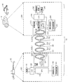
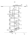
- FIG. 1 is a schematic diagram illustrating an example of an environment in which the power transmission system 10 according to the first embodiment is placed.
- the power transmission system 10 includes a power transmission device 100, a power reception device 200, and a coil CL (see FIG. 2).
- the power transmission device 100 transmits power to the power reception device 200 wirelessly (contactlessly) according to the magnetic resonance method via the plurality of coils CL.
- the number of coils CL to be arranged is n and is arbitrary.
- the coil CL is, for example, formed in an annular shape and covered with a resin cover to be insulated.
- the coil CL is, for example, a helical coil or a spiral coil.
- the coil CL includes a power transmission coil CLA and a power reception coil CLB.
- the power transmission coil CLA is a primary coil
- the power reception coil CLB is a secondary coil.
- the coil CL may include one or more relay coils CLC (Booster Coil) disposed between the power transmission coil CLA and the power reception coil CLB.
- the relay coils CLC are arranged substantially in parallel, and more than half of the opening surfaces formed by the relay coils CLC overlap. The interval between the plurality of relay coils CLC is ensured, for example, at least the radius of the relay coil CLC.
- the power transmission coil CLA is provided in the power transmission device 100.
- the power receiving coil CLB is provided in the power receiving device 200.
- the relay coil CLC may be provided in the power transmission device 100, the power reception device 200, or provided separately from the power transmission device 100 and the power reception device 200. A part of the relay coil CLC may be provided in the power transmission device 100, and the other part may be provided in the power reception device 200.
- the power transmission device 100 is installed in the ship 50.
- the power receiving device 200 is installed in the underwater vehicle 60 (for example, the submersible boat 70 or the submarine excavator 80).
- Each coil CL is disposed in water (for example, in the sea).
- a part of the ship 50 exists above the water surface 90 (for example, the sea surface), that is, on the water, and the other part of the ship 50 exists below the water surface 90, that is, in the water.
- the ship 50 can move on the water, for example, can move freely on the water of the data acquisition location.
- the power transmission device 100 of the ship 50 and the power transmission coil CLA are connected by the electric wire 20.
- the electric wire 20 is connected to, for example, a driver 151 (see FIG. 2) in the power transmission device 100 via a water connector (not shown).
- the underwater vehicle 60 exists underwater or at the bottom 95 (for example, the seabed) and travels underwater or the bottom 95. For example, it is possible to move freely to the data acquisition point according to an instruction from the ship 50 on the water.
- the instruction from the ship 50 may be transmitted by communication via each coil CL, or may be transmitted by other communication methods.
- Each coil CL is connected to the coupling body 30 and is arranged at equal intervals, for example.
- the distance between adjacent coils CL (coil interval) is, for example, a distance of the order of 100 m.
- the coil interval is, for example, about half the diameter of the coil CL.
- the power transmission frequency is 10 kHz or less. The reason for setting the power transmission frequency to 10 kHz will be described later. Note that the lower the power transmission frequency, the longer the power transmission distance, the larger the coil CL, and the longer the coil interval.
- the inductance of the coil CL is determined based on the transmission frequency, and the length and the number of turns of the coil CL are determined.
- the length of the coil CL is, for example, several meters to several hundred meters. Further, as the thickness of the coil CL is increased, the electric resistance in the coil CL is reduced and the power loss is reduced.
- the power transmitted through the coil CL is, for example, 50 W or more, and may be on the kW order.
- the number of the linked bodies 30 is three, but is not limited thereto.
- a weight 40 is connected to the end of the coupling body 30 on the power receiving coil CLB side.
- a buoy 45 is connected to the end of the coupling body 30 on the power transmission coil CLA side.
- the movement of the connection body 30 can be restricted by the weight 40, and the movement of each coil CL fixed to the connection body 30 can be restricted. Therefore, even if a water flow occurs in the water, the movement of each coil CL is restricted by the weight 40, so that it is possible to suppress a reduction in the efficiency of power transmission using the coil CL.
- FIG. 2 is a block diagram illustrating a configuration example of the power transmission system 10.
- the power transmission system 10 includes a power transmission device 100 and a power reception device 200.
- the power transmission apparatus 100 includes a power source 110, an ADC (AC / DC Converter) 120, a CPU (Central Processing Unit) 130, an information communication unit 140, and a power transmission circuit 150.
- ADC AC / DC Converter
- CPU Central Processing Unit
- the ADC 120 converts AC power supplied from the power source 110 into DC power.
- the converted DC power is sent to the power transmission circuit 150.
- the CPU 130 controls the operation of each unit (for example, the power supply 110, the ADC 120, the information communication unit 140, and the power transmission circuit 150) of the power transmission device 100.
- the information communication unit 140 includes a modulation / demodulation circuit 141 for modulating or demodulating communication data communicated with the power receiving apparatus 200.
- the information communication unit 140 transmits control information from the power transmission apparatus 100 to the power reception apparatus 200 via the coil CL.
- the information communication unit 140 receives data from the power receiving device 200 to the power transmitting device 100 via the coil CL.
- This data includes, for example, search result data obtained by underwater exploration or bottom exploration by the power receiving device 200.
- the information communication unit 140 allows the underwater vehicle 60 to quickly perform data communication with the underwater vehicle 60 while performing operations such as data collection.
- the power transmission circuit 150 includes a driver 151 and a resonance circuit 152.
- the driver 151 converts the DC power from the ADC 120 into an AC voltage (pulse waveform) having a predetermined frequency.
- the resonance circuit 152 includes a capacitor CA and a power transmission coil CLA, and generates an AC voltage with a sine wave waveform from an AC voltage with a pulse waveform from the driver 151.
- the power transmission coil CLA resonates at a predetermined resonance frequency according to the AC voltage applied from the driver 151.
- the power transmission coil CLA is impedance matched to the output impedance of the power transmission device 100.
- the power receiving apparatus 200 includes a power receiving circuit 210, a CPU 220, a charge control circuit 230, a secondary battery 240, and an information communication unit 250.
- the power receiving circuit 210 includes a rectifier circuit 211, a regulator 212, and a resonance circuit 213.
- the resonance circuit 213 includes a capacitor CB and a power reception coil CLB, and receives AC power transmitted from the power transmission coil CLA.
- the power receiving coil CLB is impedance matched to the input impedance of the power receiving device 200.
- the rectifier circuit 211 converts AC power induced in the power receiving coil CLB into DC power.
- the regulator 212 converts the DC voltage sent from the rectifier circuit 211 into a predetermined voltage that is suitable for charging the secondary battery 240.
- the CPU 220 controls the operation of each unit of the power receiving device 200 (for example, the power receiving circuit 210, the charging control circuit 230, the secondary battery 240, and the information communication unit 250).
- the charging control circuit 230 controls charging to the secondary battery 240 according to the type of the secondary battery 240. For example, when the secondary battery 240 is a lithium ion battery, the charging control circuit 230 starts charging the secondary battery 240 with a constant voltage and DC power from the regulator 212.
- the secondary battery 240 stores the electric power transmitted from the power transmission device 100.
- the secondary battery 240 is, for example, a lithium ion battery.
- the information communication unit 250 includes a modulation / demodulation circuit 251 for modulating or demodulating communication data communicated with the power transmission device 100.
- the information communication unit 250 receives control information from the power transmission device 100 to the power reception device 200 via the coil CL.
- the information communication unit 250 transmits data from the power receiving device 200 to the power transmitting device 100 via the coil CL.
- This data includes, for example, search result data obtained by underwater exploration or bottom exploration by the power receiving device 200.
- the information communication unit 250 allows the underwater vehicle 60 to quickly perform data communication with the ship 50 while performing operations such as data collection.
- the relay coil CLC forms a resonance circuit together with the capacitor CC, like the power transmission coil CLA and the power reception coil CLB. That is, in this embodiment, electric power is transmitted by the magnetic resonance method by arranging the resonance circuits in multiple stages in water.
- the resonance circuit 152 when a current flows through the power transmission coil CLA of the power transmission device 100, a magnetic field is generated around the power transmission coil CLA.
- the generated vibration of the magnetic field is transmitted to a resonance circuit including a relay coil CLC that resonates at the same frequency or a resonance circuit 213 including a power receiving coil CLB.
- a current is excited in the relay coil CLC due to the vibration of the magnetic field, a current flows, and a magnetic field is further generated around the relay coil CLC.
- the generated vibration of the magnetic field is transmitted to a resonance circuit including another relay coil CLC that resonates at the same frequency or a resonance circuit 213 including a power receiving coil CLB.
- an alternating current is induced in the power receiving coil CLB by the vibration of the magnetic field of the relay coil CLC or the power transmitting coil CLA.
- the induced alternating current is rectified, converted into a predetermined voltage, and the secondary battery 240 is charged.
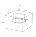
- FIG. 3 shows a simulation model 300 for investigating the propagation characteristics of the magnetic field emitted from the power transmission coil CLA.
- the simulation model 300 includes a power transmission coil CLA model and an analysis area 310.
- the power transmission coil CLA is modeled with a coil diameter of 10 m, a coil wire diameter of 0.2 m, and a coil turn number of 1.
- the measurement of propagation characteristics by simulation is performed by, for example, a PC (Personal Computer) (not shown).
- Analysis area 310 is an area of x direction (horizontal direction): 15 m, y direction (vertical direction): 10 m, and z direction (depth direction): 15 m.
- vacuum vacuum, also simply referred to as “V”
- water water, also simply referred to as “W”
- seawater water (sea), also simply referred to as “WS”).
- V vacuum
- W water
- WS seawater
- the center point of the analysis area 310 is set as the origin.
- the center point of the power transmission coil CLA coincides with the center point of the analysis area 310.
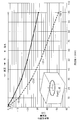
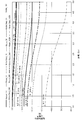
- FIG. 4 shows the frequency characteristics of the attenuation amount of the magnetic field strength Hy at the origin of the analysis area 310 (the center point of the power transmission coil CLA).
- the attenuation of the magnetic field strength Hy is plotted in decibels (dB).
- the origin may be referred to as observation point 1 (Point 1).
- FIG. 4 shows that the magnetic field strength Hy at the observation point 1 does not change with frequency in a vacuum.
- the attenuation amount of the magnetic field strength Hy increases as the frequency increases. Furthermore, the amount of attenuation is larger in the sea than in the case of underwater.
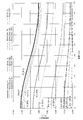
- FIG. 5 shows the frequency characteristics of the attenuation amount of the magnetic field strength Hy at a position shifted by ⁇ 5 m from the observation point 1 (origin) in the analysis area 310 in the y direction (longitudinal direction).
- the attenuation amount of the magnetic field strength Hy is plotted in decibels (dB).
- dB decibels
- a position shifted by ⁇ 5 m in the vertical direction from the observation point 1 (origin) may be referred to as an observation point 2 (Point 2).
- FIG. 5 shows that the magnetic field strength Hy at the observation point 2 does not change with frequency in a vacuum.
- the attenuation amount of the magnetic field strength Hy increases as the frequency increases as in the case of the observation point 1. Furthermore, the amount of attenuation is larger in the sea than in the case of underwater.
- the value of the magnetic field strength Hy is reduced by the distance from the power transmission coil CLA, but the tendency is similar to that at the observation point 1.
- FIG. 7 is a plot of the distance characteristics of the magnetic field strength Hy shown in FIG. 6 in decibel values (dB).
- the magnetic field strength Hy in the sea is about 94% of the vacuum magnetic field strength Hy.
- the magnetic field strength Hy in the sea is about 78% of the vacuum magnetic field strength Hy.
- the magnetic field strength Hy in the sea is about 41% of the vacuum magnetic field strength Hy.
- the magnetic field strength Hy in the sea is about 16% of the vacuum magnetic field strength Hy.
- the magnetic field strength Hy in the sea is about 2% of the vacuum magnetic field strength Hy.
- the magnetic field strength Hy in the sea is about 90% of the vacuum magnetic field strength Hy.
- the magnetic field strength Hy in the sea is about 71% of the vacuum magnetic field strength Hy.
- the magnetic field strength Hy in the sea is about 28% of the vacuum magnetic field strength Hy.
- the magnetic field strength Hy in the sea is about 6% of the vacuum magnetic field strength Hy.
- the magnetic field strength Hy in the sea is about 0.1% of the vacuum magnetic field strength Hy.
- the magnetic field strength Hy is about a maximum as compared with the case of the vacuum. It can be seen that it is attenuated to 20%.
- the underwater vehicle 60 receives power supply at a distance of several meters from the power transmission coil CLA (or the relay coil CLC), but when the magnetic field strength Hy is attenuated to about 20% at maximum, The contactless power transmission cannot be performed efficiently for the middle traveling vehicle 60.
- a magnetic field strength of about 30% of the vacuum ratio is required at least in the region of several meters from the power transmission coil CLA. . Therefore, in non-contact power transmission in the sea, it is necessary to set the frequency of the alternating voltage applied to the power transmission coil CLA to 10 kHz or less.
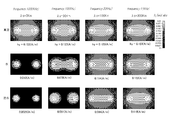
- FIG. 8 shows the magnetic field intensity distribution around the power transmission coil CLA for each material (vacuum, water, seawater) set in the analysis area 301.
- FIG. 8 shows magnetic field strength distributions corresponding to four analysis frequencies (1 kHz, 3 kHz, 10 kHz, 100 kHz).
- FIG. 9 is a schematic diagram illustrating an example of an environment in which the power transmission system 400 according to the second embodiment is placed.
- the same reference numerals are used for portions common to the first embodiment.
- the description common to the first embodiment will be omitted as appropriate.
- the power transmission system 400 is different from the first embodiment in that a reflection coil CLR is provided between the power transmission coil CLA and the water surface 90.
- the reflection coil CLR reflects the magnetic field emitted from the power transmission coil CLA toward the water surface 90 toward the water bottom 95. Thereby, it can suppress that the magnetic field discharge
- FIG. Therefore, it is possible to suppress interference between the magnetic field emitted from the power transmission coil CLA and the communication of the ultra long wave (VLF) band or the ultra long wave (ULF) on or in water.
- VLF ultra long wave
- ULF ultra long wave
- the reflection coil CLR is not connected to a capacitor like the power reception coil CLB and the relay coil CLC, and does not form a resonance circuit. That is, the reflection coil CLR is a closed loop without a capacitor.
- the reflection coil CLR is not necessarily a single ring as shown in FIG.
- a second reflection coil having a smaller coil diameter than the reflection coil CLR may be disposed inside the reflection coil CLR so as to be concentric with the reflection coil CLR.
- FIG. 10 shows simulation models 500 and 600 for investigating the magnetic field propagation characteristics of the power transmission system 400 in the sea.
- the simulation model 500 includes a power transmission coil CLA model and an analysis area 510.
- the power transmission coil CLA is modeled with a coil diameter of 10 m, a coil wire diameter of 0.2 m, and a coil turn number of 1.
- the analysis area 510 is a rectangular parallelepiped region of x direction (horizontal direction): 15 m, y direction (vertical direction): 30 m, and z direction (depth direction): 15 m.
- seawater is set as the material of the analysis area 510, and the strength of the magnetic field propagating in the seawater is investigated.
- an alternating current having an amplitude of 1 A and a frequency of 3 kHz is supplied to the power transmission coil CLA.
- the center point of the upper surface (zx plane) of the rectangular parallelepiped in the analysis area 510 is set as the origin.
- the center point of the power transmission coil CLA is a position shifted by ⁇ 10 m in the y direction with respect to the origin.
- the simulation model 600 includes a power transmission coil CLA, three relay coils (CLC1, CLC2, CLC3), two reflection coils (CLR1, CLR2), and an analysis area 610.
- the power transmission coil CLA, the relay coils CLC1 to CLC3, and the reflection coil CLR1 have the same shape, and are modeled with a coil diameter of 10 m, a coil wire diameter of 0.2 m, and a coil turn number of 1.
- the shape of the reflection coil CLR2 is modeled as a coil diameter: 5 m, a coil wire diameter: 0.2 m, and the number of coil turns: 1.
- the center point of the reflection coil CLR2 overlaps the center point of the reflection coil CLR1. Be placed.
- the purpose of the simulation model 600 is to investigate the difference in magnetic field strength depending on the presence or absence of the relay coils (CLC1 to CLC3) and the reflection coils (CLR1, CLR2) by comparison with the simulation model 500.
- Analysis area 610 is a rectangular parallelepiped region having x direction (horizontal direction): 15 m, y direction (vertical direction): 30 m, and z direction (depth direction): 15 m, similarly to analysis area 510.
- seawater is set as the material of the analysis area 610.
- an alternating current having an amplitude of 1 A and a frequency of 3 kHz is supplied to the power transmission coil CLA.
- the center point of the upper surface (zx plane) of the rectangular parallelepiped in the analysis area 610 is set as the origin.
- the center point of the power transmission coil CLA is a position shifted by ⁇ 10 m in the y direction with respect to the origin.
- the center point of the relay coil CLC1 is shifted by ⁇ 15 m in the y direction with respect to the origin.
- the center point of the relay coil CLC2 is a position shifted by ⁇ 20 m in the y direction with respect to the origin.
- the center point of the relay coil CLC3 is a position shifted by ⁇ 25 m in the y direction with respect to the origin.
- the center points of the reflection coils CLR1 and CLR2 are shifted by ⁇ 5 m in the y direction with respect to the origin.
- FIG. 11 shows the magnetic field propagation characteristics of the simulation models 500 and 600 in the sea.
- the magnetic field strength of the simulation model 600 is larger than the magnetic field strength of the simulation model 500 in a region where the depth from the sea surface is deeper than 10 m (y ⁇ 10).
- the three relay coils (CLC1 to CLC3) cause magnetic resonance in a chain manner by the magnetic field generated from the power transmission coil CLA.
- the magnetic field strength can be kept high even in the region of y ⁇ 10.
- the magnetic field strength of the simulation model 600 is smaller than the magnetic field strength of the simulation model 500. This is because, as described above, in the simulation model 600, the magnetic field generated from the power transmission coil CLA is reflected by the two reflection coils (CLR1, CLR2) to the seabed. Therefore, by arranging the reflection coils CLR1 and CLR2, the strength of the magnetic field radiated from the water surface can be reduced.
- the magnetic field intensity at the origin (sea surface) is reduced by 5.3 dB compared to the case where there is no reflection coil.
- the frequency of the AC voltage applied to the power transmission coil CLA is set to 10 kHz or less. Therefore, in the region of approximately half the diameter of the power transmission coil CLA from the power transmission coil CLA.
- the magnetic field strength of about 30% of the vacuum ratio can be maintained at least. Therefore, it is possible to efficiently perform non-contact power transmission to the underwater vehicle 60 moving in the sea. Therefore, in non-contact power transmission in the sea, it is necessary to set the frequency of the alternating voltage applied to the power transmission coil CLA to 10 kHz or less.
- the reflection coil CLR is provided between the power transmission coil CLA and the water surface 90, the magnetic field emitted from the power transmission coil CLA toward the water surface 90 is directed toward the water bottom 95. Can be reflected. Thereby, it can suppress that the magnetic field discharge
- FIG. Therefore, it is possible to suppress interference between the magnetic field emitted from the power transmission coil CLA and the communication of the ultra long wave (VLF) band or the ultra long wave (ULF) on or in water.
- VLF ultra long wave
- ULF ultra long wave
- the movement of the power transmission coil CLA is suppressed by the weight 40 even in an environment where there is a flow of water. Therefore, the underwater vehicle 60 does not need to be in contact with the power transmission coil CLA even in an environment where there is an underwater flow, and can be stably supplied with power by suppressing a decrease in efficiency of power transmission by the magnetic resonance method. Can do. Therefore, the underwater vehicle 60 can receive continuous power supply while performing activities such as data collection, and the operating rate of the underwater vehicle 60 when receiving power supply is improved. Therefore, the power transmission device 100 can improve the efficiency of data collection activities in water.
- the power transmission device 100 can transmit power wirelessly by the magnetic resonance method by using the power transmission coil CLA of the power transmission device 100 and the power reception coil CLB of the power reception device 200. Moreover, since the underwater vehicle 60 can receive power without moving the underwater vehicle 60 to a predetermined power supply location, the underwater vehicle 60 can move freely even during power supply, and position-free power transmission is possible. It becomes. Therefore, the power transmission device 100 can suppress the activity of the underwater vehicle 60 underwater or at the bottom 95 from being inhibited. Therefore, the underwater vehicle 60 can expand the work range even during charging, and can be continuously charged during work. Moreover, since the underwater vehicle 60 can be charged at an arbitrary timing, the working time can be shortened.
- the power transmission device 100 can extend the power transmission distance by continuous electromagnetic induction by using the relay coil CLC. For example, as illustrated in FIG. 1, by arranging the relay coils CLC in multiple stages from the vicinity of the water surface 90 toward the bottom of the water, the power transmission device 100 can transmit power to a deep water position (for example, a water depth of 1000 m or more). In this case, the power transmission device 100 can wirelessly transmit power to the underwater vehicle 60 that performs mining and investigation of the seabed resources, and can suppress a decrease in the operating rate of the underwater vehicle 60 during power feeding.
- a deep water position for example, a water depth of 1000 m or more.
- the power transmission device 100 can wirelessly transmit power to the underwater vehicle 60 that performs mining and investigation of the seabed resources, and can suppress a decrease in the operating rate of the underwater vehicle 60 during power feeding.
- the underwater vehicle 60 since the underwater vehicle 60 does not need to be equipped with a large battery for operation without power supply, the underwater vehicle 60 can be reduced in size and weight.
- the first embodiment has been described as an example of the technique in the present disclosure.
- the technology in the present disclosure is not limited to this, and can also be applied to embodiments in which changes, replacements, additions, omissions, and the like are performed.
- the power transmission system 10 is exemplified by a submarine camera system that performs data collection or the like in the sea or the sea floor, but may be applied to other uses.
- the power receiving device 200 may be provided in an underwater robot or an unmanned explorer equipped with various sensors, and may be disposed in the water or in the bottom 95. This makes it possible to manage marine resources and aquaculture, maintain and manage infrastructure systems such as bridges and dams, and monitor the seabed of harbors, etc., using underwater robots and unmanned explorers.
- the power transmission coil CLA, the relay coil CLC, and the power reception coil CLB are arranged side by side from the water surface 90 toward the water bottom 95, but the arrangement direction of the coil CL is this. Not limited to.
- the power transmission coil CLA, the relay coil CLC, and the power reception coil CLB may be arranged side by side in the direction along the water surface 90 or the water bottom 95. Thereby, the power transmission apparatus 100 can transmit electric power horizontally in water.
- the CPUs 130 and 220 are exemplified, but a processor other than the CPUs 130 and 220 may be used.
- the processor may be physically configured in any manner. Further, if a programmable processor is used, the processing contents can be changed by changing the program, so that the degree of freedom in designing the processor can be increased.
- the processor may be composed of one semiconductor chip or physically composed of a plurality of semiconductor chips. When configured by a plurality of semiconductor chips, each control of the first embodiment may be realized by separate semiconductor chips. In this case, it can be considered that a plurality of semiconductor chips constitute one processor.
- the processor may be configured by a member (capacitor or the like) having a function different from that of the semiconductor chip. Further, one semiconductor chip may be configured so as to realize the functions of the processor and other functions.
- the power transmission apparatus 100 transmits electric power to the underwater vehicle 60 having the power receiving coil CLB in water.
- the power transmission device 100 includes a power transmission coil CLA that transmits power to the power reception coil CLB via a magnetic field, a power transmission unit that transmits an AC voltage having a frequency of 10 kHz or less to the power transmission coil CLA, and a first capacitor.
- the first capacitor is connected to the power transmission coil CLA and forms a resonance circuit 152 that resonates with the power transmission coil CLA at the above frequency.
- the power transmission unit is, for example, a driver 151.
- the first capacitor is, for example, a capacitor CA.
- the underwater vehicle 60 since the underwater vehicle 60 does not need to move to the vicinity of the power transmission device 100 when receiving power supply, it can receive power while performing activities such as data collection. Therefore, the power transmission device 100 can improve the operation rate of the underwater vehicle 60 during power feeding, and can improve the efficiency of activities such as underwater data collection of the underwater vehicle 60. Moreover, since the frequency of the alternating voltage applied to the power transmission coil CLA is set to 10 kHz or less, a desired magnetic field strength can be maintained in a region approximately half the diameter of the power transmission coil CLA from the power transmission coil CLA. Therefore, non-contact power transmission can be efficiently performed with respect to the underwater vehicle 60 that moves underwater.
- the power transmission device 100 includes at least one relay coil CLC that transmits power to the power reception coil CLB using a magnetic field from the power transmission coil CLA, at least one second capacitor, the power transmission coil CLA, and the relay coil CLC. And a connecting body 30 to be connected.
- the second capacitor is connected to the relay coil CLC and forms a resonance circuit that resonates with the relay coil CLC at the above frequency.
- the second capacitor is, for example, a capacitor CC.
- the power transmission device 100 can extend the power transmission distance using the relay coil CLC. Moreover, since the power transmission apparatus 100 can restrict
- the power transmission coil CLA may transmit power in a direction substantially orthogonal to the water surface 90.
- the power transmission apparatus 100 can extend the power transmission distance in the depth direction, can supply power to the underwater vehicle 60 located in a deep water location (deep sea), and improve the work efficiency of the underwater vehicle 60. it can.
- the power transmission coil CLA may transmit power and communicate data.
- the underwater vehicle 60 can charge power from the power transmission device 100 while suppressing a decrease in activity efficiency such as data collection, and can perform data communication with the underwater vehicle 60.
- the power transmission device 100 may include a reflection coil CLR that reflects the magnetic field generated by the power transmission coil CLA toward the water bottom 95.
- the power transmission apparatus 100 can suppress the magnetic field emitted from the power transmission coil CLA from being released from the water surface 90, and the magnetic field emitted from the power transmission coil CLA and the ultra-long wave band or the ultra-long wave on the water or in water. Interference with communication can be suppressed.
- This disclosure is useful for a power transmission device that can improve the operation rate of the underwater vehicle during power feeding.
Landscapes
- Engineering & Computer Science (AREA)
- Mechanical Engineering (AREA)
- Power Engineering (AREA)
- Computer Networks & Wireless Communication (AREA)
- Transportation (AREA)
- Aviation & Aerospace Engineering (AREA)
- Chemical & Material Sciences (AREA)
- Combustion & Propulsion (AREA)
- Ocean & Marine Engineering (AREA)
- Charge And Discharge Circuits For Batteries Or The Like (AREA)
Abstract
給電時の水中航走体の稼働率を向上できる送電装置を提供する。 送電装置(100)は、水中において、受電コイル(CLB)を有する水中航走体(60)に電力を伝送する。送電装置(100)は、磁界を介して受電コイル(CLB)に電力を伝送する送電コイル(CLA)と、周波数が10kHz以下の交流電圧を送電コイル(CLA)へ送電する送電部と、送電コイル(CLA)に接続されると共に、送電コイル(CLA)と共に上記周波数で共振する共振回路(152)を形成する第1のコンデンサと、を備える。
Description
本開示は、水中において無線で送電する送電装置に関する。
従来、送電装置としての水中基地局が、受電装置としての水中航走体との間で、磁気共鳴方式を用いて非接触で電力伝送することが知られている(例えば特許文献1参照)。この送電装置は、送電用共鳴コイルと、風船と、風船制御機構と、を具備する。送電用共鳴コイルは、磁界共鳴方式により受電装置の受電用共鳴コイルに非接触で電力伝送する。風船は、送電用共鳴コイルを内包する。風船制御機構は、風船を電力伝送時に膨張させることにより、送電用共鳴コイルと受電用共鳴コイルとの間の水を排除する。
また、13.56MHz帯の周波数を用いる電磁誘導方式を利用して、電力とデータをIC搭載媒体に送信するアンテナ装置が知られている(例えば特許文献2参照)。このアンテナ装置は、信号電流が給電される少なくとも1つの給電ループアンテナと信号電流が給電されない少なくとも1つの無給電ループアンテナを有し、給電ループアンテナが発生する磁界を利用して無給電ループアンテナにも信号電流を発生させ、給電ループアンテナの通信範囲を拡大させる点を開示している。
水中の電磁波は、発散、吸収、反射等の現象により減衰することが知られている。特に、電磁波の周波数が高くなるほど電磁波の減衰量は大きくなる。特許文献2に記載のような13.56MHz帯の電磁波を用いて、水中航走体に対して非接触電力伝送を行う場合は、電磁波の伝搬強度は1メートルあたり数十分の1に減衰してしまうので、非接触電力伝送を効率的に行うことは困難である。
本開示は、上記事情に鑑みてなされたものであり、水中における水中航走体への非接触電力伝送を効率的に行うことが可能な送電装置を提供する。
本開示の送電装置は、水中において、受電コイルを有する水中航走体に電力を伝送する。送電装置は、磁界を介して受電コイルに電力を伝送する送電コイルと、周波数が10kHz以下の交流電圧を送電コイルへ送電する送電部と、送電コイルに接続されると共に、送電コイルと共に上記周波数で共振する共振回路を形成する第1のコンデンサと、を備える。
本開示によれば、水中における水中航走体への非接触電力伝送を効率的に行うことが可能になる。
以下、適宜図面を参照しながら、実施形態を詳細に説明する。但し、必要以上に詳細な説明は省略する場合がある。例えば、既によく知られた事項の詳細説明や実質的に同一の構成に対する重複説明を省略する場合がある。これは、以下の説明が不必要に冗長になることを避け、当業者の理解を容易にするためである。尚、添付図面及び以下の説明は、当業者が本開示を十分に理解するために提供されるものであり、これらにより特許請求の範囲に記載の主題を限定することは意図されていない。
(第1の実施形態)
[構成等]
図1は、第1の実施形態における電力伝送システム10が置かれる環境の一例を示す模式図である。電力伝送システム10は、送電装置100、受電装置200、及びコイルCLを備える(図2参照)。送電装置100は、受電装置200に対して、複数のコイルCLを介して、磁気共鳴方式に従ってワイヤレス(無接点)で電力伝送する。配置されるコイルCLの数は、n個であり、任意である。
[構成等]
図1は、第1の実施形態における電力伝送システム10が置かれる環境の一例を示す模式図である。電力伝送システム10は、送電装置100、受電装置200、及びコイルCLを備える(図2参照)。送電装置100は、受電装置200に対して、複数のコイルCLを介して、磁気共鳴方式に従ってワイヤレス(無接点)で電力伝送する。配置されるコイルCLの数は、n個であり、任意である。
コイルCLは、例えば、環状に形成され、樹脂のカバーで覆われて絶縁されている。コイルCLは、例えば、ヘリカルコイルやスパイラルコイルである。コイルCLは、送電コイルCLA及び受電コイルCLBを含む。送電コイルCLAは、一次コイル(Primary Coil)であり、受電コイルCLBは、二次コイル(Secondary Coil)である。
また、コイルCLは、送電コイルCLAと受電コイルCLBとの間に配置された1つ以上の中継コイルCLC(Booster Coil)を含んでもよい。中継コイルCLC同志は、略平行に配置され、中継コイルCLCにより形成される開口面の半分以上が重なる。複数の中継コイルCLC間の間隔は、例えば中継コイルCLCの半径以上確保される。
送電コイルCLAは、送電装置100に設けられる。受電コイルCLBは、受電装置200に設けられる。中継コイルCLCは、送電装置100に設けられても、受電装置200に設けられても、送電装置100及び受電装置200とは別に設けられてもよい。中継コイルCLCは、一部が送電装置100に設けられ、他の一部が受電装置200に設けられてもよい。
送電装置100は、船舶50に設置される。受電装置200は、水中航走体60(例えば潜水艇70や水底掘削機80)に設置される。各コイルCLは、水中(例えば海中)に配置される。
船舶50の一部は、水面90(例えば海面)より上部つまり水上に存在し、船舶50の他の一部は、水面90よりも下部つまり水中に存在する。船舶50は、水上で移動可能であり、例えばデータ取得場所の水上へ自由に移動可能である。船舶50の送電装置100と送電コイルCLAとの間は、電線20により接続される。電線20は、水上のコネクタ(不図示)を介して、例えば送電装置100内のドライバ151(図2参照)と接続される。
水中航走体60は、水中又は水底95(例えば海底)に存在し、水中又は水底95を航走する。例えば、水上の船舶50からの指示により、データ取得ポイントへ自由に移動可能である。船舶50からの指示は、各コイルCLを介した通信により伝送されてもよいし、その他の通信方法により伝送されてもよい。
各コイルCLは、連結体30と接続され、例えば等間隔に配置される。隣り合うコイルCL間の距離(コイル間隔)は、例えば100mオーダーの距離である。コイル間隔は、例えばコイルCLの直径の半分程度の長さである。送電周波数は、10kHz以下とする。送電周波数を10kHzとした理由については後で説明する。尚、送電周波数が低周波であるほど、電力伝送距離が長くなり、コイルCLを大きくでき、コイル間隔を長くできる。
また、送電周波数に基づいてコイルCLのインダクタンスが定まり、コイルCLの長さと巻き数とが定まる。コイルCLの長さは、例えば数m~数100mである。また、コイルCLの太さが太い程、コイルCLでの電気抵抗が減り、電力損失が小さくなる。また、コイルCLを介して伝送される電力は、例えば50W以上であり、kWオーダーでもよい。
図1では、連結体30の数が3つであるが、これに限られない。連結体30における受電コイルCLB側の端部には、錘40が接続される。連結体30における送電コイルCLA側の端部には、ブイ(Buoy)45が接続される。
錘40により、連結体30の移動を規制でき、連結体30に固定された各コイルCLの移動を規制できる。よって、水中において水流が発生しても、錘40により各コイルCLの移動が規制されるので、コイルCLを用いた電力伝送の効率が低下することを抑制できる。
図2は、電力伝送システム10の構成例を示すブロック図である。電力伝送システム10は、送電装置100及び受電装置200を備える。
送電装置100は、電源110、ADC(AC/DC Converter)120、CPU(Central Processing Unit)130、情報通信部140、及び送電回路150、を備える。
ADC120は、電源110から供給される交流電力を直流電力に変換する。変換された直流電力は、送電回路150へ送られる。
CPU130は、送電装置100の各部(例えば電源110、ADC120、情報通信部140、送電回路150)の動作を統括する。
情報通信部140は、受電装置200との間で通信される通信データを変調又は復調するための変復調回路141を含む。情報通信部140は、例えば、送電装置100から受電装置200への制御情報を、コイルCLを介して送信する。情報通信部140は、例えば、受電装置200から送電装置100へのデータを、コイルCLを介して受信する。このデータは、例えば、受電装置200により水中探査や水底探査された探査結果のデータが含まれる。情報通信部140により、水中航走体60がデータ収集等の作業しながら、水中航走体60との間で迅速にデータ通信できる。
送電回路150は、ドライバ151及び共振回路152を含む。ドライバ151は、ADC120からの直流電力を所定の周波数の交流電圧(パルス波形)に変換する。共振回路152は、コンデンサCAと送電コイルCLAとを含んで構成され、ドライバ151からのパルス波形の交流電圧から正弦波波形の交流電圧を生成する。送電コイルCLAは、ドライバ151から印加される交流電圧に応じて、所定の共振周波数で共振する。尚、送電コイルCLAは、送電装置100の出力インピーダンスにインピーダンス整合される。
受電装置200は、受電回路210、CPU220、充電制御回路230、2次電池240、及び情報通信部250を備える。
受電回路210は、整流回路211、レギュレータ212、及び共振回路213を含む。共振回路213は、コンデンサCBと受電コイルCLBとを含んで構成され、送電コイルCLAから送電された交流電力を受電する。尚、受電コイルCLBは、受電装置200の入力インピーダンスにインピーダンス整合される。整流回路211は、受電コイルCLBに誘起された交流電力を直流電力に変換する。レギュレータ212は、整流回路211から送られる直流電圧を、2次電池240の充電に適合する所定の電圧に変換する。
CPU220は、受電装置200の各部(例えば受電回路210、充電制御回路230、2次電池240、情報通信部250)の動作を統括する。
充電制御回路230は、2次電池240の種別に応じて2次電池240への充電を制御する。例えば、2次電池240がリチウムイオン電池の場合、充電制御回路230は、定電圧で、レギュレータ212からの直流電力により2次電池240への充電を開始する。
2次電池240は、送電装置100から伝送された電力を蓄積する。2次電池240は、例えばリチウムイオン電池である。
情報通信部250は、送電装置100との間で通信される通信データを変調又は復調するための変復調回路251を含む。情報通信部250は、例えば、送電装置100から受電装置200への制御情報を、コイルCLを介して受信する。情報通信部250は、例えば、受電装置200から送電装置100へのデータを、コイルCLを介して送信する。このデータは、例えば、受電装置200により水中探査や水底探査された探査結果のデータが含まれる。情報通信部250により、水中航走体60がデータ収集等の作業しながら、船舶50との間で迅速にデータ通信できる。
尚、中継コイルCLCは、送電コイルCLA及び受電コイルCLBと同様に、コンデンサCCとともに共振回路を構成する。つまり、本実施形態では、共振回路が水中において多段に配置されることで、磁気共鳴方式により電力が伝送される。
次に、送電装置100から受電装置200への電力伝送について説明する。
共振回路152では、送電装置100の送電コイルCLAに電流が流れると送電コイルCLAの周囲に磁場が発生する。発生した磁場の振動は、同一の周波数で共振する中継コイルCLCを含む共振回路又は受電コイルCLBを含む共振回路213に伝達される。
中継コイルCLCを含む共振回路では、磁場の振動により中継コイルCLCに電流が励起され、電流が流れ、中継コイルCLCの周囲に更に磁場が発生する。発生した磁場の振動は、同一の周波数で共振する他の中継コイルCLCを含む共振回路又は受電コイルCLBを含む共振回路213に伝達される。
共振回路213では、中継コイルCLC又は送電コイルCLAの磁場の振動により、受電コイルCLBに交流電流が誘起される。誘起された交流電流が整流され、所定の電圧に変換され、2次電池240に充電される。
[伝搬特性のシミュレーション]
図3は、送電コイルCLAから発せられる磁界の伝搬特性を調査するためのシミュレーションモデル300を示す。シミュレーションモデル300は、送電コイルCLAのモデルと解析エリア310とから構成される。送電コイルCLAは、コイル直径:10m、コイル線径:0.2m、コイルターン数:1としてモデル化を行っている。シミュレーションによる伝搬特性の測定は、例えば図示しないPC(Personal Coputer)により行われる。
図3は、送電コイルCLAから発せられる磁界の伝搬特性を調査するためのシミュレーションモデル300を示す。シミュレーションモデル300は、送電コイルCLAのモデルと解析エリア310とから構成される。送電コイルCLAは、コイル直径:10m、コイル線径:0.2m、コイルターン数:1としてモデル化を行っている。シミュレーションによる伝搬特性の測定は、例えば図示しないPC(Personal Coputer)により行われる。
解析エリア310は、x方向(横方向):15m、y方向(縦方向):10m、z方向(奥行き方向):15mの領域である。シミュレーションでは、解析エリア310の材質として真空(Vacuum、単に「V」とも記す)、水(Water、単に「W」とも記記す)、海水(Water(Sea)、単に「W.S」とも記す)の3種類を設定し、これら3種類の物質中を伝搬する磁界の強度を調査する。シミュレーションモデル300では、送電コイルCLAに対して、振幅が1Aの交流電流を流すものとする。また、交流電流の周波数(解析周波数)としては、1kHz~100kHzの範囲を設定している。また、シミュレーションモデル300では、解析エリア310の中心点を原点として設定している。送電コイルCLAの中心点と解析エリア310の中心点は一致している。
図4は、解析エリア310の原点(送電コイルCLAの中心点)における磁界強度Hyの減衰量の周波数特性を示す。図4では、磁界強度Hyの減衰量をデシベル(dB)単位でプロットしている。以後、原点については観測ポイント1(Point1)と称する場合がある。また、原点を(x、y、z)=(0、0、0)と表現する場合もある。
図4によると、真空では、観測ポイント1における磁界強度Hyは周波数によって変化していないことがわかる。一方、水中および海中では、周波数が大きくなるにしたがって、磁界強度Hyの減衰量が大きくなっていることがわかる。さらに、海中では、水中の場合に比べて、更に減衰量が大きくなっている。
図5は、解析エリア310の観測ポイント1(原点)からy方向(縦方向)に-5mシフトした位置における磁界強度Hyの減衰量の周波数特性を示す。図5では、図4と同様に、磁界強度Hyの減衰量をデシベル(dB)単位でプロットしている。以後、観測ポイント1(原点)から縦方向に-5mシフトした位置を観測ポイント2(Point2)と称する場合がある。また、観測ポイント2を(x、y、z)=(0、-5、0)と表現する場合もある。
図5によると、真空では、観測ポイント2における磁界強度Hyは周波数によって変化していないことがわかる。一方、水中および海中では、観測ポイント1の場合と同様に周波数が大きくなるにしたがって、磁界強度Hyの減衰量が大きくなっていることがわかる。さらに、海中では、水中の場合に比べて、更に減衰量が大きくなっている。観測ポイント2では、送電コイルCLAから距離が離れている分、磁界強度Hyの値が小さくなっているが、観測ポイント1と同様の傾向になる。
図6では、解析エリア301で設定した各材質(真空、水、海水)について、解析周波数1kHz、3kHz、10kHz、30kHz、100kHzにおける磁界強度Hy(単位:A/m)の距離特性をプロットしている。距離特性のプロットは、観測ポイント1(y=0m)からy軸に沿った観測ポイント2(y=-5m)の区間について行っている。また、図7は、図6に示す磁界強度Hyの距離特性をデシベル値(dB)でプロットしたものである。
図4~7を参照すると、観測ポイント1では、周波数が1kHzの場合、海中の磁界強度Hyは真空の磁界強度Hyの約94%になる。周波数が3kHzの場合、海中の磁界強度Hyは真空の磁界強度Hyの約78%になる。周波数が10kHzの場合、海中の磁界強度Hyは真空の磁界強度Hyの約41%になる。周波数が30kHzの場合、海中の磁界強度Hyは真空の磁界強度Hyの約16%になる。周波数が100kHzの場合、海中の磁界強度Hyは真空の磁界強度Hyの約2%になる。
また、観測ポイント2では、周波数が1kHzの場合、海中の磁界強度Hyは真空の磁界強度Hyの約90%になる。周波数が3kHzの場合、海中の磁界強度Hyは真空の磁界強度Hyの約71%になる。周波数が10kHzの場合、海中の磁界強度Hyは真空の磁界強度Hyの約28%になる。周波数が30kHzの場合、海中の磁界強度Hyは真空の磁界強度Hyの約6%になる。周波数が100kHzの場合、海中の磁界強度Hyは真空の磁界強度Hyの約0.1%になる。
このように、海中では周波数が10kHzを超えてしまうと、観測ポイント1~観測ポイント2の区間(すなわち、送電コイルCLAから5m程度の領域)では、磁界強度Hyが真空の場合に比べて最大約20%まで減衰されることが理解できる。水中航走体60は、送電コイルCLA(または、中継コイルCLC)から数メートル程度離間して電力供給を受けることになるが、磁界強度Hyが最大20%程度にまで減衰してしまうと、水中航走体60に対して効率的に非接触電力伝送を行うことはできない。
海中で水中航走体60に対して効率的に非接触電力伝送を行うには、送電コイルCLAから数m程度の領域であると、最低でも真空比の30%程度の磁界強度が必要になる。したがって、海中での非接触電力伝送では、送電コイルCLAに印加する交流電圧の周波数を10kHz以下に設定することが必要になる。
図8は、解析エリア301で設定した各材質(真空、水、海水)について、送電コイルCLAの周囲の磁界強度分布を示したものである。図8では4つの解析周波数(1kHz、3kHz、10kHz、100kHz)に対応する磁界強度分布を示している。
(第2の実施形態)
図9は、第2の実施形態における電力伝送システム400が置かれる環境の一例を示す模式図である。図9において、第1の実施形態と共通する部分については同じ符号を用いている。また、説明の簡潔のために、第1の実施形態と共通する部分については、適宜、説明を省略する。
図9は、第2の実施形態における電力伝送システム400が置かれる環境の一例を示す模式図である。図9において、第1の実施形態と共通する部分については同じ符号を用いている。また、説明の簡潔のために、第1の実施形態と共通する部分については、適宜、説明を省略する。
[構成等]
電力伝送システム400は、送電コイルCLAと水面90の間に反射コイルCLRを有する点で、第1の実施形態と相違する。反射コイルCLRは、送電コイルCLAから水面90の方向へ放出される磁界を水底95の方向へ反射する。これにより、送電コイルCLAから放出された磁界が水面90から放出されることを抑制できる。よって、送電コイルCLAから放出された磁界と水上や水中での超長波(VLF)帯や極超長波(ULF)の通信との干渉を抑制することが可能になる。
電力伝送システム400は、送電コイルCLAと水面90の間に反射コイルCLRを有する点で、第1の実施形態と相違する。反射コイルCLRは、送電コイルCLAから水面90の方向へ放出される磁界を水底95の方向へ反射する。これにより、送電コイルCLAから放出された磁界が水面90から放出されることを抑制できる。よって、送電コイルCLAから放出された磁界と水上や水中での超長波(VLF)帯や極超長波(ULF)の通信との干渉を抑制することが可能になる。
尚、反射コイルCLRは、送電コイルCLAとの共振を避ける必要があるため、受電コイルCLBや中継コイルCLCの様にコンデンサが接続されておらず、共振回路を形成しない。すなわち、反射コイルCLRはコンデンサの無い閉ループになる。
また、反射コイルCLRは、図9に示すような一つの環とは限らない。例えば、反射コイルCLRの内側に、反射コイルCLRよりもコイル直径の小さな第2の反射コイルを反射コイルCLRと同心円状に配置してもよい。これにより、送電コイルCLAから発生する磁界を水底方向へ反射可能な面積が増えるので、水面90から磁界が放出されることをより確実に抑えることができる。
[伝搬特性のシミュレーション]
図10は、電力伝送システム400の海中における磁界伝搬特性を調査するためのシミュレーションモデル500、600を示す。シミュレーションモデル500は、送電コイルCLAのモデルと解析エリア510とから構成される。送電コイルCLAは、コイル直径:10m、コイル線径:0.2m、コイルターン数:1としてモデル化を行っている。
図10は、電力伝送システム400の海中における磁界伝搬特性を調査するためのシミュレーションモデル500、600を示す。シミュレーションモデル500は、送電コイルCLAのモデルと解析エリア510とから構成される。送電コイルCLAは、コイル直径:10m、コイル線径:0.2m、コイルターン数:1としてモデル化を行っている。
解析エリア510は、x方向(横方向):15m、y方向(縦方向):30m、z方向(奥行き方向):15mの直方体領域である。シミュレーションでは、解析エリア510の材質として、海水を設定し、海水中を伝搬する磁界の強度を調査する。シミュレーションモデル500では、送電コイルCLAに対して、振幅:1A、周波数:3kHzの交流電流を流すものとする。また、シミュレーションモデル500では、解析エリア510の直方体上面(zx平面)の中心点を原点として設定している。送電コイルCLAの中心点は、原点に対してy方向に-10mシフトした位置になる。
シミュレーションモデル600は、送電コイルCLA、3つの中継コイル(CLC1、CLC2、CLC3)、2つの反射コイル(CLR1、CLR2)及び解析エリア610から構成される。送電コイルCLA、中継コイルCLC1~CLC3、及び反射コイルCLR1は、形状が同じであり、コイル直径:10m、コイル線径:0.2m、コイルターン数:1としてモデル化を行っている。反射コイルCLR2の形状は、コイル直径:5m、コイル線径:0.2m、コイルターン数:1としてモデル化を行っており、反射コイルCLR2の中心点は、反射コイルCLR1の中心点と重なって配置される。
シミュレーションモデル600の目的は、シミュレーションモデル500との対比によって、中継コイル(CLC1~CLC3)及び反射コイル(CLR1、CLR2)の有無による磁界強度の差を調査することである。
解析エリア610は、解析エリア510と同様に、x方向(横方向):15m、y方向(縦方向):30m、z方向(奥行き方向):15mの直方体領域である。シミュレーションでは、解析エリア610の材質として、海水を設定している。シミュレーションモデル600では、送電コイルCLAに対して、振幅:1A、周波数:3kHzの交流電流を流すものとする。
また、シミュレーションモデル600では、解析エリア610の直方体上面(zx平面)の中心点を原点として設定している。送電コイルCLAの中心点は、原点に対してy方向に-10mシフトした位置になる。中継コイルCLC1の中心点は、原点に対してy方向に-15mシフトした位置になる。中継コイルCLC2の中心点は、原点に対してy方向に-20mシフトした位置になる。中継コイルCLC3の中心点は、原点に対してy方向に-25mシフトした位置になる。反射コイルCLR1及びCLR2の中心点は、原点に対してy方向に-5mシフトした位置になる。
図11は、シミュレーションモデル500および600の海中における磁界伝搬特性を示している。図11では、送電コイルCLAの中心点(x=0m、y=-10m、z=0m)における磁界強度を基準として、y軸上に沿った深さ方向の相対的な磁界強度をプロットしている。
図11を参照すると、海面からの深さが10mよりも深い領域(y<-10)では、シミュレーションモデル600の磁界強度は、シミュレーションモデル500の磁界強度よりも大きくなっていることが理解できる。これは、前述したように、シミュレーションモデル600では、送電コイルCLAから発せられた磁界によって、3つの中継コイル(CLC1~CLC3)が連鎖的に磁気共鳴を起こすからである。これにより、シミュレーションモデル600(すなわち電力伝送システム400)では、y<-10の領域でも磁界強度を高く維持することができる。中継コイルCLC1~CLC3を深さ方向に多段的に配置することによって、水中航走体60に電力供給を行うことが可能な領域が増大する。
より具体的には、中継コイルCLC1の中心点(x=0m、y=-15m、z=0m)における磁界強度は、中継コイルが無い場合に比べて3.1dB増大する。また、中継コイルCLC2の中心点(x=0m、y=-20m、z=0m)における磁界強度は、中継コイルが無い場合に比べて12.5dB増大する。中継コイルCLC3の中心点(x=0m、y=-25m、z=0m)における磁界強度は、中継コイルが無い場合に比べて20.2dB増大する。また、ポイント(x=0m、y=-30m、z=0m)における磁界強度は、中継コイルが無い場合に比べて25.1dB増大する。
一方、海面からの深さが10mよりも浅い領域(y>-10)では、シミュレーションモデル600の磁界強度は、シミュレーションモデル500の磁界強度よりも小さくなっていることが理解できる。これは、前述したように、シミュレーションモデル600では、送電コイルCLAから発せられた磁界が、2つの反射コイル(CLR1、CLR2)によって、海底へ反射されるからである。したがって、反射コイルCLR1、CLR2を配置することによって、水面から放射される磁界の強度を小さくすることが可能となる。
より具体的には、反射コイルCLR1及びCLR2の中心点(x=0m、y=-5m、z=0m)における磁界強度は、反射コイルが無い場合に比べて4dB減少する。また、原点(海面)における磁界強度は、反射コイルが無い場合に比べて5.3dB減少する。
[第1,第2の実施形態の効果等]
このように、第1の実施形態の電力伝送システム10によれば、送電コイルCLAに印加する交流電圧の周波数を10kHz以下にするので、送電コイルCLAから送電コイルCLAの直径の概半分の領域で、最低でも真空比の30%程度の磁界強度を維持することができる。したがって、海中を移動する水中航走体60に対して効率的に非接触電力伝送を行うことが可能になる。したがって、海中での非接触電力伝送では、送電コイルCLAに印加する交流電圧の周波数を10kHz以下に設定することが必要になる。
このように、第1の実施形態の電力伝送システム10によれば、送電コイルCLAに印加する交流電圧の周波数を10kHz以下にするので、送電コイルCLAから送電コイルCLAの直径の概半分の領域で、最低でも真空比の30%程度の磁界強度を維持することができる。したがって、海中を移動する水中航走体60に対して効率的に非接触電力伝送を行うことが可能になる。したがって、海中での非接触電力伝送では、送電コイルCLAに印加する交流電圧の周波数を10kHz以下に設定することが必要になる。
また、第2の実施形態の電力伝送システム400によれば、送電コイルCLAと水面90の間に反射コイルCLRを備えるので、送電コイルCLAから水面90の方向へ放出される磁界を水底95の方向へ反射させることができる。これにより、送電コイルCLAから放出された磁界が水面90から放出されることを抑制できる。よって、送電コイルCLAから放出された磁界と水上や水中での超長波(VLF)帯や極超長波(ULF)の通信との干渉を抑制することが可能になる。
また、第1,第2の実施形態の電力伝送システム10、400によれば、送電コイルCLAは、水中の流れがある環境においても錘40によって移動が抑制される。そのため、水中航走体60は、水中の流れがある環境においても、送電コイルCLAに接触する必要なく、磁気共鳴方式による電力伝送の効率低下を抑制して、安定的に電力の供給を受けることができる。従って、水中航走体60は、データ収集等の活動を行いながら連続給電を受けることが可能になり、給電を受ける際の水中航走体60の稼働率が向上する。よって、送電装置100は、水中でのデータ収集活動の効率を向上できる。
また、送電装置100は、送電装置100の送電コイルCLA及び受電装置200の受電コイルCLBを用いることで、磁気共鳴方式によりワイヤレスで電力伝送できる。また、送電装置100は、水中航走体60が所定の給電場所に移動することなく電力を受けられるので、給電時においても水中航走体60は自由に移動でき、ポジションフリーの電力伝送が可能となる。よって、送電装置100は、水中航走体60による水中や水底95での活動が阻害されることを抑制できる。よって、水中航走体60は、充電中でも作業範囲を拡大でき、作業中に連続充電できる。また、水中航走体60は、任意のタイミングで充電できるので、作業時間を短縮できる。
また、送電装置100は、中継コイルCLCを用いることで、連続した電磁誘導により電力伝送距離を延長できる。例えば、図1に示したように、中継コイルCLCを多段に水面90付近から水底方向へ配置することで、送電装置100は、水深の深い位置(例えば水深1000m以上)まで電力伝送可能となる。この場合、送電装置100は、海底資源の採掘や調査を行う水中航走体60に対して、ワイヤレスで電力伝送でき、給電時の水中航走体60の稼働率の低下を抑制できる。
また、無給電により動作するための大型のバッテリを水中航走体60が備える必要がないので、水中航走体60を小型化、軽量化できる。
(他の実施形態)
以上のように、本開示における技術の例示として、第1の実施形態を説明した。しかし、本開示における技術は、これに限定されず、変更、置き換え、付加、省略などを行った実施形態にも適用できる。
以上のように、本開示における技術の例示として、第1の実施形態を説明した。しかし、本開示における技術は、これに限定されず、変更、置き換え、付加、省略などを行った実施形態にも適用できる。
第1,第2の実施形態では、電力伝送システム10として、海中又は海底においてデータ収集等を行う海底カメラシステムを例示したが、これ以外の用途に適用されてもよい。例えば、受電装置200を様々なセンサを備える水中ロボットや無人探査機に設け、水中や水底95に配置してもよい。これにより、水中ロボットや無人探査機により、水産資源や養殖の管理、橋梁やダムなどのインフラシステムの維持管理、港湾などの海底監視が可能となる。
第1,第2の実施形態では、水面90から水底95に向かって、送電コイルCLA、中継コイルCLC、及び受電コイルCLBが並んで配置されることを例示したが、コイルCLの配置方向はこれに限られない。例えば、水面90や水底95に沿う方向に、送電コイルCLA、中継コイルCLC、及び受電コイルCLBが並んで配置されてもよい。これにより、送電装置100は、水中で水平方向に電力伝送できる。
第1,第2の実施形態では、CPU130,220を例示したが、CPU130,220以外のプロセッサが用いられてもよい。プロセッサは、物理的にどのように構成してもよい。また、プログラム可能なプロセッサを用いれば、プログラムの変更により処理内容を変更できるので、プロセッサの設計の自由度を高めることができる。プロセッサは、1つの半導体チップで構成してもよいし、物理的に複数の半導体チップで構成してもよい。複数の半導体チップで構成する場合、第1の実施形態の各制御をそれぞれ別の半導体チップで実現してもよい。この場合、それらの複数の半導体チップで1つのプロセッサを構成すると考えることができる。また、プロセッサは、半導体チップと別の機能を有する部材(コンデンサ等)で構成してもよい。また、プロセッサが有する機能とそれ以外の機能とを実現するように、1つの半導体チップを構成してもよい。
(本開示の一形態の概要)
このように、送電装置100は、水中において、受電コイルCLBを有する水中航走体60に電力を伝送する。送電装置100は、磁界を介して受電コイルCLBに電力を伝送する送電コイルCLAと、周波数が10kHz以下の交流電圧を送電コイルCLAへ送電する送電部と、第1のコンデンサを備える。第1のコンデンサは、送電コイルCLAに接続されると共に、送電コイルCLAと共に上記周波数で共振する共振回路152を形成する。尚、送電部は、例えばドライバ151である。第1のコンデンサは、例えばコンデンサCAである。
このように、送電装置100は、水中において、受電コイルCLBを有する水中航走体60に電力を伝送する。送電装置100は、磁界を介して受電コイルCLBに電力を伝送する送電コイルCLAと、周波数が10kHz以下の交流電圧を送電コイルCLAへ送電する送電部と、第1のコンデンサを備える。第1のコンデンサは、送電コイルCLAに接続されると共に、送電コイルCLAと共に上記周波数で共振する共振回路152を形成する。尚、送電部は、例えばドライバ151である。第1のコンデンサは、例えばコンデンサCAである。
これにより、水中航走体60は、給電を受ける際に送電装置100付近に移動する必要がないので、データ収集等の活動を行いながら給電を受けることができる。従って、送電装置100は、給電時の水中航走体60の稼働率が向上でき、水中航走体60の水中でのデータ収等の活動の効率を向上できる。また、送電コイルCLAに印加する交流電圧の周波数を10kHz以下にするので、送電コイルCLAから送電コイルCLAの直径の概半分の領域で、所望の磁界強度を維持できる。従って、水中を移動する水中航走体60に対して効率的に非接触電力伝送を実施できる。
また、送電装置100は、送電コイルCLAからの磁界を用いて受電コイルCLBに電力を伝送する少なくとも1つの中継コイルCLCと、少なくとも1つの第2のコンデンサと、送電コイルCLAと中継コイルCLCとを連結する連結体30と、を備えてもよい。第2のコンデンサは、中継コイルCLCに接続されると共に、中継コイルCLCと共に上記周波数で共振する共振回路を形成する。尚、第2のコンデンサは、例えばコンデンサCCである。
これにより、送電装置100は、中継コイルCLCを用いて、電力伝送距離を延長できる。また、送電装置100は、連結体30により各コイルCLの移動を制限でき、共振回路による共振効率を向上できるので、電力伝送効率を向上できる。従って、送電装置100は、水中において水流が発生しても、水中航走体60の充電効率が低下することを抑制できる。
また、送電コイルCLAは、水面90と略直交する方向に電力を伝送してもよい。
これにより、送電装置100は、深さ方向に電力伝送距離を延長でき、水深の深い場所(深海)に位置する水中航走体60に対して給電でき、水中航走体60の作業効率を向上できる。
また、送電コイルCLAは、電力を伝送するとともに、データを通信してもよい。
これにより、水中航走体60は、データ収集等の活動効率の低下を抑制しながら、送電装置100からの電力を充電でき、水中航走体60との間でデータ通信できる。
また、送電装置100は、送電コイルCLAが発生する磁界を水底95に向けて反射する反射コイルCLRを備えてもよい。
これにより、送電装置100は、送電コイルCLAから放出された磁界が水面90から放出されることを抑制でき、送電コイルCLAから放出された磁界と水上や水中での超長波帯や極超長波の通信との干渉を抑制できる。
本発明を詳細にまた特定の実施態様を参照して説明したが、本発明の精神と範囲を逸脱することなく様々な変更や修正を加えることができることは当業者にとって明らかである。
本出願は、2015年7月21日出願の日本特許出願特願2015-144090に基づくものであり、その内容はここに参照として取り込まれる。
本出願は、2015年7月21日出願の日本特許出願特願2015-144090に基づくものであり、その内容はここに参照として取り込まれる。
本開示は、給電時の水中航走体の稼働率を向上できる送電装置等に有用である。
10,400 電力伝送システム
20 電線
30 連結体
40 錘
45 ブイ
50 船舶
60 水中航走体
70 潜水艇
80 水底掘削機
90 水面
95 水底
100 送電装置
110 電源
120 ADC
130 CPU
140 情報通信部
141 変復調回路
150 送電回路
151 ドライバ
152 共振回路
200 受電装置
210 受電回路
211 整流回路
212 レギュレータ
220 CPU
230 充電制御回路
240 2次電池
250 情報通信部
251 変復調回路
300,500,600 シミュレーションモデル
310,510,610 解析エリア
CL コイル
CLA 送電コイル
CLB 受電コイル
CLC,CLC1,CLC2,CLC3 中継コイル
CLR,CLR1,CLR2 反射コイル
CA,CB,CC コンデンサ
Claims (5)
- 水中において、受電コイルを有する水中航走体に電力を伝送する送電装置であって、
磁界を介して前記受電コイルに電力を伝送する送電コイルと、
周波数が10kHz以下の交流電圧を前記送電コイルへ送電する送電部と、
前記送電コイルに接続されると共に、前記送電コイルと共に前記周波数で共振する共振回路を形成する第1のコンデンサと、
を備える送電装置。 - 請求項1に記載の送電装置であって、更に、
前記送電コイルからの磁界を用いて前記受電コイルに電力を伝送する少なくとも1つの中継コイルと、
前記中継コイルに接続されると共に、前記中継コイルと共に前記周波数で共振する共振回路を形成する少なくとも1つの第2のコンデンサと、
前記送電コイルと前記中継コイルとを連結する連結体と、
を備える送電装置。 - 請求項2に記載の送電装置であって、
前記送電コイルは、水面と略直交する方向に電力を伝送する、送電装置。 - 請求項1~3のいずれか1項に記載の送電装置であって、
前記送電コイルは、前記電力を伝送するとともに、データを通信する、送電装置。 - 請求項1~4のいずれか1項に記載の送電装置であって、更に、
前記送電コイルが発生する磁界を水底に向けて反射する反射コイルを備える、送電装置。
Priority Applications (1)
| Application Number | Priority Date | Filing Date | Title |
|---|---|---|---|
| US15/746,327 US10549652B2 (en) | 2015-07-21 | 2016-05-27 | Power transmission device |
Applications Claiming Priority (2)
| Application Number | Priority Date | Filing Date | Title |
|---|---|---|---|
| JP2015-144090 | 2015-07-21 | ||
| JP2015144090A JP6531942B2 (ja) | 2015-07-21 | 2015-07-21 | 送電装置 |
Publications (1)
| Publication Number | Publication Date |
|---|---|
| WO2017013825A1 true WO2017013825A1 (ja) | 2017-01-26 |
Family
ID=57834946
Family Applications (1)
| Application Number | Title | Priority Date | Filing Date |
|---|---|---|---|
| PCT/JP2016/002600 WO2017013825A1 (ja) | 2015-07-21 | 2016-05-27 | 送電装置 |
Country Status (3)
| Country | Link |
|---|---|
| US (1) | US10549652B2 (ja) |
| JP (1) | JP6531942B2 (ja) |
| WO (1) | WO2017013825A1 (ja) |
Cited By (3)
| Publication number | Priority date | Publication date | Assignee | Title |
|---|---|---|---|---|
| WO2018003568A1 (ja) * | 2016-06-30 | 2018-01-04 | パナソニック株式会社 | 送電装置 |
| WO2018207899A1 (ja) * | 2017-05-10 | 2018-11-15 | パナソニック株式会社 | 送電装置 |
| WO2019187607A1 (ja) * | 2018-03-28 | 2019-10-03 | パナソニックIpマネジメント株式会社 | 水中通信装置及び水中通信システム |
Families Citing this family (6)
| Publication number | Priority date | Publication date | Assignee | Title |
|---|---|---|---|---|
| JP6568133B2 (ja) | 2017-03-30 | 2019-08-28 | パナソニック株式会社 | 伝送コイル及び送電装置 |
| KR101986362B1 (ko) * | 2017-09-20 | 2019-06-05 | 한국철도기술연구원 | 고주파 전원 전달 장치 |
| CN107947385B (zh) * | 2017-12-14 | 2020-10-09 | 中国船舶重工集团公司第七一九研究所 | 一种基于无线电能传输的易分离式水下变压器 |
| WO2019187708A1 (ja) * | 2018-03-27 | 2019-10-03 | パナソニック株式会社 | 送電装置 |
| US11491935B2 (en) * | 2019-10-25 | 2022-11-08 | Sea Clear Power Inc. | Systems and methods for distribution of power in a marine vessel, ATVS, and vehicles |
| JP2022034812A (ja) * | 2020-08-19 | 2022-03-04 | ソフトバンク株式会社 | 充電システム |
Citations (6)
| Publication number | Priority date | Publication date | Assignee | Title |
|---|---|---|---|---|
| JP2004096182A (ja) * | 2002-08-29 | 2004-03-25 | Reideikku:Kk | 水中又は地中通信装置 |
| JP2013215049A (ja) * | 2012-04-02 | 2013-10-17 | Advantest Corp | ワイヤレス給電装置およびワイヤレス送電システム |
| WO2014129531A1 (ja) * | 2013-02-20 | 2014-08-28 | 日本電気株式会社 | 電力伝送システム、送電装置、受電装置、及び電力伝送方法 |
| JP2014222975A (ja) * | 2013-05-13 | 2014-11-27 | 株式会社Ihi | 非接触給電システム |
| JP2015023669A (ja) * | 2013-07-18 | 2015-02-02 | Ihi運搬機械株式会社 | 非接触給電システム |
| WO2015087724A1 (ja) * | 2013-12-09 | 2015-06-18 | 有限会社 アール・シー・エス | 磁力波アンテナおよびそれを用いる磁力波通信装置 |
Family Cites Families (19)
| Publication number | Priority date | Publication date | Assignee | Title |
|---|---|---|---|---|
| US5301096A (en) * | 1991-09-27 | 1994-04-05 | Electric Power Research Institute | Submersible contactless power delivery system |
| JP2005102101A (ja) | 2003-09-01 | 2005-04-14 | Matsushita Electric Ind Co Ltd | ゲートアンテナ装置 |
| US7511502B2 (en) * | 2007-01-05 | 2009-03-31 | Kabushiki Kaisha Toshiba | Magnetic resonance imaging apparatus |
| US20110076940A1 (en) * | 2009-09-25 | 2011-03-31 | Mark Rhodes | Underwater wireless communications hotspot |
| JP2011183950A (ja) * | 2010-03-09 | 2011-09-22 | Universal Tokki Kk | 磁場生成装置およびこれを有する船舶 |
| US8482250B2 (en) * | 2010-08-06 | 2013-07-09 | Cynetic Designs Ltd. | Inductive transmission of power and data through ceramic armor panels |
| WO2013042224A1 (ja) * | 2011-09-21 | 2013-03-28 | パイオニア株式会社 | 非接触電力送電装置、非接触電力受電装置、及び非接触給電システム |
| JP2013110805A (ja) * | 2011-11-18 | 2013-06-06 | Nec Corp | 非接触給電システム及び給電方法 |
| EP3076517B1 (en) | 2011-12-07 | 2017-07-26 | IHI Corporation | Power transmission system |
| JP2013126326A (ja) * | 2011-12-15 | 2013-06-24 | Toyota Motor Corp | 非接触受電装置およびそれを搭載する車両、非接触送電装置、ならびに非接触給電システム |
| CN104040833B (zh) * | 2012-01-12 | 2016-08-24 | 富士通株式会社 | 送电装置以及送受电系统 |
| JP2013219972A (ja) | 2012-04-11 | 2013-10-24 | Ihi Corp | 水中電力供給システム |
| EP2674950A1 (en) * | 2012-06-11 | 2013-12-18 | Tyco Electronics Nederland B.V. | Contactless connector, contactless connector system, and a manufacturing method for the contactless connector |
| US9444270B2 (en) * | 2012-08-02 | 2016-09-13 | Sandisk Technologies Llc | Wireless power transfer |
| GB201215152D0 (en) * | 2012-08-24 | 2012-10-10 | Imp Innovations Ltd | Maximising DC to load efficiency for inductive power transfer |
| JP5643270B2 (ja) * | 2012-09-13 | 2014-12-17 | トヨタ自動車株式会社 | 車両および非接触給電システム |
| US9362776B2 (en) * | 2012-11-27 | 2016-06-07 | Qualcomm Incorporated | Wireless charging systems and methods |
| WO2014181669A1 (ja) | 2013-05-10 | 2014-11-13 | 株式会社Ihi | 非接触給電システム |
| JP6038386B1 (ja) * | 2015-03-23 | 2016-12-07 | 三菱電機株式会社 | 双方向非接触給電装置および双方向非接触給電システム |
-
2015
- 2015-07-21 JP JP2015144090A patent/JP6531942B2/ja active Active
-
2016
- 2016-05-27 WO PCT/JP2016/002600 patent/WO2017013825A1/ja active Application Filing
- 2016-05-27 US US15/746,327 patent/US10549652B2/en active Active
Patent Citations (6)
| Publication number | Priority date | Publication date | Assignee | Title |
|---|---|---|---|---|
| JP2004096182A (ja) * | 2002-08-29 | 2004-03-25 | Reideikku:Kk | 水中又は地中通信装置 |
| JP2013215049A (ja) * | 2012-04-02 | 2013-10-17 | Advantest Corp | ワイヤレス給電装置およびワイヤレス送電システム |
| WO2014129531A1 (ja) * | 2013-02-20 | 2014-08-28 | 日本電気株式会社 | 電力伝送システム、送電装置、受電装置、及び電力伝送方法 |
| JP2014222975A (ja) * | 2013-05-13 | 2014-11-27 | 株式会社Ihi | 非接触給電システム |
| JP2015023669A (ja) * | 2013-07-18 | 2015-02-02 | Ihi運搬機械株式会社 | 非接触給電システム |
| WO2015087724A1 (ja) * | 2013-12-09 | 2015-06-18 | 有限会社 アール・シー・エス | 磁力波アンテナおよびそれを用いる磁力波通信装置 |
Cited By (8)
| Publication number | Priority date | Publication date | Assignee | Title |
|---|---|---|---|---|
| WO2018003568A1 (ja) * | 2016-06-30 | 2018-01-04 | パナソニック株式会社 | 送電装置 |
| US10790705B2 (en) | 2016-06-30 | 2020-09-29 | Panasonic Corporation | Power transmission device |
| WO2018207899A1 (ja) * | 2017-05-10 | 2018-11-15 | パナソニック株式会社 | 送電装置 |
| US11031820B2 (en) | 2017-05-10 | 2021-06-08 | Panasonic Corporation | Power transmitting device |
| US20210273490A1 (en) * | 2017-05-10 | 2021-09-02 | Panasonic Corporation | Power transmitting device |
| US11502550B2 (en) | 2017-05-10 | 2022-11-15 | Panasonic Holdings Corporation | Power transmitting device that transmits power to power receiving device having power receiving coil in water |
| WO2019187607A1 (ja) * | 2018-03-28 | 2019-10-03 | パナソニックIpマネジメント株式会社 | 水中通信装置及び水中通信システム |
| US10965381B2 (en) | 2018-03-28 | 2021-03-30 | Panasonic Intellectual Property Management Co., Ltd. | Underwater communication device and underwater communication system |
Also Published As
| Publication number | Publication date |
|---|---|
| JP2017028832A (ja) | 2017-02-02 |
| US20180215277A1 (en) | 2018-08-02 |
| JP6531942B2 (ja) | 2019-06-19 |
| US10549652B2 (en) | 2020-02-04 |
Similar Documents
| Publication | Publication Date | Title |
|---|---|---|
| WO2017013825A1 (ja) | 送電装置 | |
| JP7222035B2 (ja) | 送電装置 | |
| WO2018079082A1 (ja) | 送電装置 | |
| JP6594373B2 (ja) | 送電装置 | |
| JP6620906B1 (ja) | 水中通信装置及び水中通信システム | |
| US20210166855A1 (en) | Transmission coil and power transmission apparatus | |
| US11569689B2 (en) | Power receiving device, power transmitting device, and underwater power supply system | |
| US20210281328A1 (en) | Underwater communication device and underwater communication system | |
| JP6492651B2 (ja) | 給電システム、移動体および給電装置 | |
| JP2016207872A (ja) | 無線給電システムおよび無線給電方法 | |
| Duarte et al. | Experimental evaluation of coupling coils for underwater wireless power transfer | |
| WO2016170769A1 (ja) | 無線給電システムおよび無線給電方法 | |
| KR101462138B1 (ko) | 전자기 감응 공명 방식의 수중 무선전력전송 장치 | |
| JP2016059146A (ja) | 海水中給電システム | |
| JP2016127626A (ja) | 無線給電システム、移動体および情報収集システム | |
| Santos et al. | Experimental Evaluation of Coupling Coils for Underwater Wireless Power Transfer | |
| Rodrigues et al. | Experimental Evaluation of TENGs for Energy Harvesting in Maritime Applications |
Legal Events
| Date | Code | Title | Description |
|---|---|---|---|
| 121 | Ep: the epo has been informed by wipo that ep was designated in this application |
Ref document number: 16827394 Country of ref document: EP Kind code of ref document: A1 |
|
| WWE | Wipo information: entry into national phase |
Ref document number: 15746327 Country of ref document: US |
|
| NENP | Non-entry into the national phase |
Ref country code: DE |
|
| 122 | Ep: pct application non-entry in european phase |
Ref document number: 16827394 Country of ref document: EP Kind code of ref document: A1 |