WO2017010396A1 - 導風ユニットおよび冷却モジュール - Google Patents
導風ユニットおよび冷却モジュール Download PDFInfo
- Publication number
- WO2017010396A1 WO2017010396A1 PCT/JP2016/070131 JP2016070131W WO2017010396A1 WO 2017010396 A1 WO2017010396 A1 WO 2017010396A1 JP 2016070131 W JP2016070131 W JP 2016070131W WO 2017010396 A1 WO2017010396 A1 WO 2017010396A1
- Authority
- WO
- WIPO (PCT)
- Prior art keywords
- opening
- duct
- air
- door
- air guide
- Prior art date
- Legal status (The legal status is an assumption and is not a legal conclusion. Google has not performed a legal analysis and makes no representation as to the accuracy of the status listed.)
- Ceased
Links
Images






Classifications
-
- B—PERFORMING OPERATIONS; TRANSPORTING
- B60—VEHICLES IN GENERAL
- B60K—ARRANGEMENT OR MOUNTING OF PROPULSION UNITS OR OF TRANSMISSIONS IN VEHICLES; ARRANGEMENT OR MOUNTING OF PLURAL DIVERSE PRIME-MOVERS IN VEHICLES; AUXILIARY DRIVES FOR VEHICLES; INSTRUMENTATION OR DASHBOARDS FOR VEHICLES; ARRANGEMENTS IN CONNECTION WITH COOLING, AIR INTAKE, GAS EXHAUST OR FUEL SUPPLY OF PROPULSION UNITS IN VEHICLES
- B60K11/00—Arrangement in connection with cooling of propulsion units
- B60K11/08—Air inlets for cooling; Shutters or blinds therefor
-
- B—PERFORMING OPERATIONS; TRANSPORTING
- B60—VEHICLES IN GENERAL
- B60K—ARRANGEMENT OR MOUNTING OF PROPULSION UNITS OR OF TRANSMISSIONS IN VEHICLES; ARRANGEMENT OR MOUNTING OF PLURAL DIVERSE PRIME-MOVERS IN VEHICLES; AUXILIARY DRIVES FOR VEHICLES; INSTRUMENTATION OR DASHBOARDS FOR VEHICLES; ARRANGEMENTS IN CONNECTION WITH COOLING, AIR INTAKE, GAS EXHAUST OR FUEL SUPPLY OF PROPULSION UNITS IN VEHICLES
- B60K11/00—Arrangement in connection with cooling of propulsion units
- B60K11/02—Arrangement in connection with cooling of propulsion units with liquid cooling
- B60K11/04—Arrangement or mounting of radiators, radiator shutters, or radiator blinds
-
- F—MECHANICAL ENGINEERING; LIGHTING; HEATING; WEAPONS; BLASTING
- F01—MACHINES OR ENGINES IN GENERAL; ENGINE PLANTS IN GENERAL; STEAM ENGINES
- F01P—COOLING OF MACHINES OR ENGINES IN GENERAL; COOLING OF INTERNAL-COMBUSTION ENGINES
- F01P11/00—Component parts, details, or accessories not provided for in, or of interest apart from, groups F01P1/00 - F01P9/00
- F01P11/10—Guiding or ducting cooling-air, to, or from, liquid-to-air heat exchangers
-
- F—MECHANICAL ENGINEERING; LIGHTING; HEATING; WEAPONS; BLASTING
- F01—MACHINES OR ENGINES IN GENERAL; ENGINE PLANTS IN GENERAL; STEAM ENGINES
- F01P—COOLING OF MACHINES OR ENGINES IN GENERAL; COOLING OF INTERNAL-COMBUSTION ENGINES
- F01P5/00—Pumping cooling-air or liquid coolants
- F01P5/02—Pumping cooling-air; Arrangements of cooling-air pumps, e.g. fans or blowers
-
- F—MECHANICAL ENGINEERING; LIGHTING; HEATING; WEAPONS; BLASTING
- F01—MACHINES OR ENGINES IN GENERAL; ENGINE PLANTS IN GENERAL; STEAM ENGINES
- F01P—COOLING OF MACHINES OR ENGINES IN GENERAL; COOLING OF INTERNAL-COMBUSTION ENGINES
- F01P1/00—Air cooling
- F01P1/06—Arrangements for cooling other engine or machine parts
-
- F—MECHANICAL ENGINEERING; LIGHTING; HEATING; WEAPONS; BLASTING
- F01—MACHINES OR ENGINES IN GENERAL; ENGINE PLANTS IN GENERAL; STEAM ENGINES
- F01P—COOLING OF MACHINES OR ENGINES IN GENERAL; COOLING OF INTERNAL-COMBUSTION ENGINES
- F01P1/00—Air cooling
- F01P2001/005—Cooling engine rooms
-
- F—MECHANICAL ENGINEERING; LIGHTING; HEATING; WEAPONS; BLASTING
- F01—MACHINES OR ENGINES IN GENERAL; ENGINE PLANTS IN GENERAL; STEAM ENGINES
- F01P—COOLING OF MACHINES OR ENGINES IN GENERAL; COOLING OF INTERNAL-COMBUSTION ENGINES
- F01P5/00—Pumping cooling-air or liquid coolants
- F01P5/02—Pumping cooling-air; Arrangements of cooling-air pumps, e.g. fans or blowers
- F01P5/04—Pump-driving arrangements
- F01P2005/046—Pump-driving arrangements with electrical pump drive
-
- F—MECHANICAL ENGINEERING; LIGHTING; HEATING; WEAPONS; BLASTING
- F01—MACHINES OR ENGINES IN GENERAL; ENGINE PLANTS IN GENERAL; STEAM ENGINES
- F01P—COOLING OF MACHINES OR ENGINES IN GENERAL; COOLING OF INTERNAL-COMBUSTION ENGINES
- F01P3/00—Liquid cooling
- F01P3/18—Arrangements or mounting of liquid-to-air heat-exchangers
-
- F—MECHANICAL ENGINEERING; LIGHTING; HEATING; WEAPONS; BLASTING
- F01—MACHINES OR ENGINES IN GENERAL; ENGINE PLANTS IN GENERAL; STEAM ENGINES
- F01P—COOLING OF MACHINES OR ENGINES IN GENERAL; COOLING OF INTERNAL-COMBUSTION ENGINES
- F01P5/00—Pumping cooling-air or liquid coolants
- F01P5/02—Pumping cooling-air; Arrangements of cooling-air pumps, e.g. fans or blowers
- F01P5/06—Guiding or ducting air to, or from, ducted fans
Definitions
- the present disclosure relates to an air guide unit and a cooling module provided in an engine room of an automobile.
- a duct for cooling an intercooler for a vehicle described in Patent Document 1 is known as one of the air guiding units such as the above-described air guiding unit.
- the intercooler cooling duct is a duct that connects an air outlet formed on the engine room side of the engine hood of the vehicle and an air inlet of the intercooler.
- the intercooler cooling duct of Patent Document 1 includes an upper end opening connected to an air outlet of the engine hood and a lower end opening that is abutted against the air intake of the intercooler when the engine hood is closed. And.
- the intercooler cooling duct supplies outside air that has passed through the engine hood and exited from the air outlet to the intercooler.
- an engine room of an automobile is provided with a cooling module that performs a cooling function, in other words, a cooling module.
- the cooling module is composed of a radiator that radiates engine cooling water, a condenser that is a radiator of an air conditioner that air-conditions the vehicle interior, a blower that generates cooling air, and a shroud that fixes them and guides the cooling air Has been.
- the heat of the refrigerant circulating in the air conditioner and the heat of the engine cooling water are dissipated by the running wind and the cooling air from the blower.
- the cooling module is usually placed in front of the engine room. Therefore, the heat discarded by the cooling module, that is, the heat transferred to the outside air by the radiator and the condenser flows to the traveling engine disposed at the rear of the vehicle with respect to the cooling module, which causes a reduction in heat radiation efficiency. .
- the inventors considered providing a duct that guides the front wind flowing into the engine room from the front of the vehicle to the space behind the engine. As a result, the front wind is guided to the engine rear space during normal vehicle travel.
- the vehicle front side of the duct becomes negative pressure, so that the blower sucks air from the front of the vehicle, Air is sucked from the space behind the engine through the duct.
- the present disclosure allows air flowing into the engine room from the front of the vehicle to be directed to the engine rear space, while the air in the engine rear space flows to the front of the vehicle through the air duct in the engine room. It aims at suppressing this.
- an air guide unit of the present disclosure includes: A wind guide unit applied to an automobile in which air flows into an engine room from an engine room opening that is opened in front of a vehicle in an engine room where a traveling engine is disposed, The air conditioner radiator and the engine cooling heat exchanger for cooling the traveling engine and the blower are fixed, and the air passing through the radiator and the engine cooling heat exchanger is guided through the engine room opening, A shroud with a vent hole, A first opening that is connected to the shroud at the ventilation hole and opens through the ventilation hole, and a second opening that opens to the rear of the vehicle with respect to the traveling engine in the engine room, the first opening and the second opening.
- An air duct that forms a flow path in the duct that allows air to flow between the And a valve portion that is provided in the air guide duct and increases or decreases the opening degree of the flow path in the duct.
- the first opening of the air guide duct is connected to the shroud through the ventilation hole and opens through the ventilation hole.
- the 2nd opening part of a wind guide duct is opened in the vehicle back with respect to a driving
- FIG. 6 is a sectional view taken along line VI-VI in FIG. 3.
- FIG. 7 is a cross-sectional view showing a state in which the opening of the revolving door minimizes the opening of the duct internal passage in the same VI-VI cross section (see FIG. 3) as FIG. It is a top view of the on-off valve of 2nd Embodiment, Comprising: It is a figure equivalent to FIG. 3 of 1st Embodiment.
- FIG. 9 is a cross-sectional view taken along the line IX-IX in FIG. 8.
- FIG. 8 is a cross-sectional view of the third embodiment in which the air guide duct and the open / close valve are cut along a cross-section corresponding to the VI-VI cross-section of FIG. 3, and corresponding to FIG. 7 of the first embodiment.
- FIG. 8 is a cross-sectional view of the third embodiment in which the air guide duct and the open / close valve are cut along a cross-section corresponding to the VI-VI cross-section of FIG. 3, and corresponding to FIG. 7 of the first embodiment.
- FIG. 8 is a cross-sectional view of the fourth embodiment in which the air guide duct and the open / close valve are cut along a cross section corresponding to the VI-VI cross section of FIG. 3, and is a view corresponding to FIG. 7 of the first embodiment.
- FIG. 8 is a cross-sectional view of the fifth embodiment in which the air guide duct and the open / close valve are cut along a cross-section corresponding to the VI-VI cross-section of FIG. 3, and corresponding to FIG. 7 of the first embodiment.
- FIG. 1 is a schematic view of the entire configuration of the cooling module 10 according to the present embodiment as viewed from above the vehicle.
- Arrows DR1 and DR2 in FIG. 1 and an arrow DR3 in FIG. 2 described later indicate the direction of the vehicle 12 on which the cooling module 10 is mounted. That is, the double-ended arrow DR1 in FIG. 1 indicates the vehicle longitudinal direction DR1, the double-ended arrow DR2 indicates the vehicle left-right direction DR2, that is, the vehicle width direction DR2, and the double-ended arrow DR3 in FIG.
- an engine room 14 is formed in the vehicle 12, in other words, in the automobile 12 in front of the automobile 12.
- the cooling module 10 is disposed from the portion between the engine room opening 2 and the traveling engine 16 to the rear of the traveling engine 16 in the vehicle longitudinal direction DR1 in the engine room 14.
- the engine room 14 is a space in which the traveling engine 16 is disposed, and is a front engine room provided in front of the vehicle with respect to the passenger compartment (that is, the passenger compartment) of the automobile 12.
- the engine room opening 2 is an opening that opens in front of the engine room 14 in the vehicle and allows air to pass in the vehicle front-rear direction DR ⁇ b> 1, and is formed in the front grill 4 of the automobile 12. Since the engine room opening 2 is provided in the front grill 4 in this way, for example, outside air in the vehicle compartment, such as traveling wind, that is, outside air passes through the engine room opening 2 and passes through the engine room opening 2 to the engine room 14. Flow into.
- the cooling module 10 includes a capacitor 20, a radiator 30, an electric fan 40, a shroud 50, an air guide duct 60, and an opening / closing valve 70 as a valve unit.
- the shroud 50, the air guide duct 60, and the open / close valve 70 constitute an air guide unit that guides air in the cooling module 10 as a whole.
- the condenser 20, the radiator 30, the electric fan 40, and the shroud 50 are disposed between the engine room opening 2 and the traveling engine 16 in the vehicle front-rear direction DR1.
- the condenser 20 is a component of an air conditioner that performs air conditioning of the vehicle interior, and constitutes a refrigeration cycle apparatus that circulates refrigerant contained in the air conditioner together with a compressor, a pressure reducing valve, and an evaporator.
- the capacitor 20 is a heat exchanger as a radiator that dissipates heat of the high-pressure refrigerant discharged from the compressor to the outside air and condenses the high-pressure refrigerant.
- the radiator 30 is disposed at the rear of the vehicle with respect to the capacitor 20 and at the front of the vehicle with respect to the electric fan 40.
- the radiator 30 is an engine cooling heat exchanger for cooling the traveling engine 16. Specifically, the radiator 30 cools the traveling engine 16 by dissipating heat of engine cooling water as a heat medium circulating in the traveling engine 16 to the outside air.
- the radiator 30 is disposed on the upstream side with respect to the electric fan 40 in the air flow direction in the introduction flow path 50a.
- the introduction flow path 50a is an air passage for guiding the air flow sucked from the engine room opening 2 through the condenser 20 and the radiator 30 to the electric fan 40 as shown by an arrow K in FIG.
- the air flow direction in the introduction flow path 50a is the flow direction of the main flow having the largest air volume among the plurality of air flows flowing through the introduction flow path 50a.
- the electric fan 40 is, for example, an axial flow blower, and generates an air flow (that is, cooling air) that passes through the condenser 20 and the radiator 30 from the front of the automobile 12 through the engine room opening 2.
- air flow that is, cooling air
- electric fan 40 sucks air that has passed through condenser 20 and radiator 30 from the front of the vehicle, and blows out the sucked air to the rear of the vehicle.
- the electric fan 40 is switched between on and off. That is, when the electric fan 40 is turned on, it operates and sucks air from the front of the vehicle as described above, and when it is turned off, it stops.
- the shroud 50 is fixed to the vehicle body 6, and the capacitor 20, the radiator 30, and the electric fan 40 are fixed to the shroud 50. They may be fixed directly or indirectly with respect to the shroud 50. In the present embodiment, for example, the radiator 30 and the electric fan 40 are directly fixed to the shroud 50.
- the capacitor 20 is directly fixed to the radiator 30, and is fixed to the shroud 50 through the radiator 30.
- the shroud 50 is a casing that forms an introduction flow path 50a for guiding the air flow sucked from the engine room opening 2 through the condenser 20 and the radiator 30 to the electric fan 40.
- the shroud 50 is an air guide member that guides air (that is, outside air) passing through the condenser 20 and the radiator 30 through the engine room opening 2.
- the shroud 50 is formed so as to surround the space formed between the capacitor 20 and the radiator 30 and the space formed between the radiator 30 and the electric fan 40 in a cylindrical shape.
- the shroud 50 is formed with a ventilation hole 50b through which a part of the air flowing through the introduction flow path 50a flows into the air guide duct 60.
- the ventilation hole 50 b is disposed on the downstream side of the radiator 30 and the upstream side of the electric fan 40 in the air flow in the introduction flow path 50 a. That is, in the vehicle front-rear direction DR ⁇ b> 1, the ventilation holes 50 b of the shroud 50 are disposed behind the radiator 30 and forward of the electric fan 40. Further, the ventilation hole 50b is disposed at a position biased to one of the left and right with respect to the electric fan 40 in the vehicle width direction DR2.
- the air guide duct 60 is an air guide pipe disposed on the upper side of the traveling engine 16 in the engine room 14, and forms an in-duct flow path 60 a, which is an air flow path 60 a through which air flows, in the air guide duct 60. ing.
- the air duct 60 has a front opening 61 as a first opening and a rear opening 62 as a second opening. Air flows between the front opening 61 and the rear opening 62.
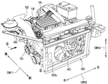
- FIG. 2 is a perspective view illustrating the air guide duct 60, the shroud 50, the electric fan 40, and the traveling engine 16 extracted from FIG.
- the rear opening 62 of the air guide duct 60 constitutes an end portion of the air guide duct 60 on the rear side of the vehicle, and opens in the engine room 14 to the rear of the vehicle with respect to the traveling engine 16.
- the rear opening 62 is open to the exhaust manifold 18 side with respect to the traveling engine 16 in the engine room 14.
- the rear side opening 62 forms a duct outlet provided on the side of the air guide duct 60 opposite to the shroud 50 side.
- the rear side opening part 62 should just be the vehicle rear side with respect to the engine 16 for driving
- the air guide duct 60 flows the air flowing in from the front opening 61 to the rear opening 62.
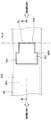
- FIG. 3 is an enlarged view of a portion III in FIG. 2, and is a plan view of the on-off valve 70.
- the open / close valve 70 is provided on the way from the front opening 61 (see FIG. 1) of the air guide duct 60 to the rear opening 62.
- the on-off valve 70 is a door mechanism that opens and closes the in-duct flow path 60a of the air guide duct 60, that is, increases or decreases the opening degree of the in-duct flow path 60a.
- the opening of the in-duct flow path 60a is the degree of opening of the in-duct flow path 60a, and the increase / decrease of the opening is to increase / decrease the cross-sectional area of the in-duct flow path 60a.
- the open / close valve 70 includes a rotating door 701, a door rotating shaft 702, and an actuator 703.
- the rotating door 701 is a so-called cantilever door having a flat plate shape as shown in FIG.
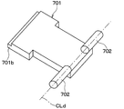
- FIG. 4 is a perspective view showing an excerpt of the pivot door 701 and the door pivot shaft 702.
- the turning door 701 and the door turning shaft 702 are made of resin, for example, and are integrally formed. Therefore, the turning door 701 and the door turning shaft 702 are configured as separate parts from the air guide duct 60.
- the door rotation shaft 702 has a cylindrical shape, and the rotation door 701 rotates about the door rotation shaft 702. In other words, the rotating door 701 rotates around the door axis CLd that is the center line of the door rotating shaft 702.
- the air guide duct 60 has connecting portions 601 on one side and the other side of the rotary door 701 in the door axial direction which is the axial direction of the door axis CLd. Yes. That is, the air guide duct 60 has a pair of connecting portions 601.
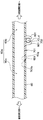
- FIG. 5 is an arrow view of the air guide duct 60 and the opening / closing valve 70 viewed from the direction of the arrow V in FIG.
- the pair of connecting portions 601 are connected to the rotating door 701 via the door rotating shaft 702, and support the rotating door 701 so as to be rotatable about the door axis CLd.
- a door rotation shaft 702 is rotatably fitted in each of the pair of connecting portions 601, whereby the connecting portion 601 supports the rotating door 701 in a rotatable manner.
- the air guide duct 60 has an opening hole 60 f provided in the middle from the front opening 61 (see FIG. 1) of the air guide duct 60 to the rear opening 62. Is formed. 6 is a sectional view taken along line VI-VI in FIG.
- the opening hole 60 f is a through hole that allows the duct internal flow path 60 a to communicate with the outside of the air guide duct 60.
- the door axis line CLd passes through a position biased toward the front opening 61 with respect to the opening hole 60f in the longitudinal direction of the air guide duct 60, and intersects the duct flow path 60a (specifically, orthogonal). Direction).
- the opening hole 60f of the wind guide duct 60 may be open to the outside of the wind guide duct 60 in any direction. However, the opening hole 60f is oriented, for example, such that when the opening hole 60f is opened, the air inflow into the opening hole 60f is not obstructed by an obstacle and the air easily flows into the opening hole 60f. Is preferred.
- the opening hole 60f of the air duct 60 and the opening / closing valve 70 are provided on the way from the front opening 61 to the rear opening 62, but even when the opening hole 60f is opened. It is preferable that the air is provided at a position where air easily flows into the opening hole 60f.
- the opening hole 60f and the opening / closing valve 70 are preferably provided in front of the vehicle as much as possible from the front opening 61 to the rear opening 62.
- the duct internal flow path 60a includes two flow paths 60b and 60c. It can be said. That is, the in-duct flow path 60 a is formed between the front side flow path 60 b as the first open side flow path between the front opening 61 and the hole forming part 602, and between the hole forming part 602 and the rear opening 62. And a rear flow path 60c as a second opening-side flow path.
- the open / close valve 70 opens and closes the front channel 60b and the opening hole 60f with respect to the rear channel 60c. More specifically, the opening degree of the in-duct flow path 60a decreases as the rotating door 701 rotates in the direction in which the front flow path 60b is closed with respect to the rear flow path 60c. As the opening degree of the flow path 60a is decreased, the opening degree of the opening hole 60f with respect to the rear side flow path 60c is increased.
- the turning door 701 fits into the opening hole 60f when the opening of the duct internal passage 60a is maximized within the movable range of the turning door 701. In that case, the rotating door 701 fits in the opening hole 60f and closes the opening hole 60f. More specifically, the rotating door 701 rotates in the air guide duct 60 to close the opening hole 60 f from the inside of the air guide duct 60.
- the opening / closing valve 70 has a door structure in which the rotating door 701 that also becomes a part of the air guide duct 60 falls to the inside of the air guide duct 60.
- the closing of the opening hole 60f by the rotating door 701 is not limited to completely closing the opening hole 60f, and the opening of the opening hole 60f is minimized within the movable range of the rotating door 701. It is. The same applies to the opening and closing of the front channel 60b.
- the opening hole 60f of the air guide duct 60 is slightly smaller than the outer shape of the rotating door 701 so as not to prevent the rotating door 701 fitted in the opening hole 60f from rotating and coming out of the opening hole 60f. It is greatly formed.
- FIG. 7 is a cross-sectional view showing a state where the pivot door 701 minimizes the opening of the duct internal passage 60a in the same VI-VI cross section (see FIG. 3) as FIG.
- the rotating door 701 has a wall surface contact portion 701b on the side edge portion opposite to the shaft connecting portion 701a bonded to the door rotating shaft 702.
- the wall surface contact portion 701 b of the rotation door 701 is included in the air guide duct 60. It contacts the channel wall surface 603 facing the inner channel 60a.
- the wall surface contact portion 701b is made of an elastic material such as rubber, and is integrally formed with a portion other than the wall surface contact portion 701b in the rotating door 701 by two-color molding or the like. Since the wall surface contact portion 701b has elasticity, when the opening of the in-duct flow path 60a is minimized, the wall surface contact section 701b is pressed against and closely contacts the flow path wall surface 603.
- the wall surface contact portion 701b of the rotating door 701 is formed on the door abutting portion 60g of the air guide duct 60 when the opening degree of the in-duct flow path 60a is maximized, that is, when the opening hole 60f is closed. On the other hand, it strikes from the inside of the air duct 60. Also in this case, the wall surface contact portion 701b is pressed against and closely contacts the door abutting portion 60g of the air guide duct 60 due to the elasticity of the wall surface contact portion 701b.
- the door abutting portion 60 g of the air guide duct 60 is a part of the peripheral edge of the air guide duct 60 that forms the opening hole 60 f.
- the opening degree of the duct internal flow path 60a is maximized by the rotation of the rotating door 701
- the opening degree of the opening hole 60f is minimized at the same time.
- the opening degree of the in-duct flow path 60a is minimized by the rotation of the rotating door 701
- the opening degree of the opening hole 60f is maximized at the same time.
- the actuator 703 of the opening / closing valve 70 is composed of an electric motor such as a stepping motor, for example, and the rotation shaft of the actuator 703 is connected to the door rotation shaft 702 as shown in FIG. Thereby, the actuator 703 can change and position the rotation position of the rotation door 701 continuously.
- the operation of the actuator 703 is controlled by the control device 72.
- the control device 72 that controls the actuator 703 has a case where the traveling speed of the automobile 12 is equal to or lower than a predetermined determination vehicle speed, and the electric fan 40 is activated to suck air from the front of the vehicle.
- the opening of the in-duct flow path 60a is minimized within the movable range of the rotating door 701. In short, as shown in FIG. 7, the front flow path 60b is closed with respect to the rear flow path 60c to open the opening hole 60f.
- the control device 72 of the actuator 703 when the control device 72 of the actuator 703 does not satisfy the condition for closing the front flow path 60b and opening the opening hole 60f, the control device 72 of the duct 603 is within the movable range of the rotary door 701. Maximize the opening. Specifically, the control device 72 is used when the traveling speed of the automobile 12 is higher than the determination vehicle speed, or when the electric fan 40 does not suck air from the front of the vehicle, for example, when the electric fan 40 is stopped. In the movable range of the rotary door 701, the opening degree of the duct internal flow path 60a is maximized. In short, in those cases, as shown in FIG. 6, the front channel 60b is opened with respect to the rear channel 60c, and the opening hole 60f is closed.
- the determination vehicle speed is experimentally determined in advance so that a low vehicle speed can be determined such that the air pressure in the introduction flow path 50a becomes a negative pressure during the operation of the electric fan 40.
- the case where the traveling speed is equal to or lower than the determination vehicle speed includes not only during low-speed traveling below the determination vehicle speed but also during stopping.
- the exhaust manifold 18 is a manifold that collects a plurality of exhaust passages connected to the traveling engine 16 into one exhaust pipe that discharges exhaust gas from the traveling engine 16.
- the exhaust manifold 18 is disposed in the rear of the vehicle with respect to the traveling engine 16 in the engine room 14.
- a turbocharger turbine and a catalyst device are arranged in addition to the exhaust manifold 18 at the rear of the engine room 14 with respect to the traveling engine 16.
- the catalyst device is a device that purifies harmful components in exhaust gas blown from the traveling engine 16 by reduction and oxidation.
- the turbocharger extracts rotational energy from the internal energy of the exhaust gas blown out from the traveling engine 16 by the turbine, operates the compressor by this rotational energy, generates compressed air, and supplies the compressed air to the intake port of the traveling engine 16.
- a turbocharger turbine is a device that extracts rotational energy from internal energy of exhaust gas.
- the duct 60 is introduced into the in-duct flow path 60a.
- the vehicle traveling wind introduced into the duct internal flow path 60 a is blown out from the rear opening 62 of the air guide duct 60 to the exhaust manifold 18 side.
- the exhaust manifold 18, the catalyst device, and the turbocharger turbine disposed in the engine rear space in the engine room 14 can be cooled by the air that is guided to the air guide duct 60 and blown out from the rear opening 62. it can.
- the engine rear space is a space behind the vehicle with respect to the traveling engine 16 in the engine room 14.
- the remaining air flow other than the air flow flowing into the air guide duct 60 is an electric fan. Inhaled into 40. The remaining air sucked in by the electric fan 40 passes around the traveling engine 16 and flows below the floor. For this reason, the traveling engine 16 is cooled by the airflow that flows from the introduction flow path 50a through the electric fan 40 to the traveling engine 16 side.
- the front opening 61 of the air guide duct 60 is connected to the shroud 50 through the ventilation hole 50b of the shroud 50 and opens through the ventilation hole 50b.
- the rear opening 62 of the air guide duct 60 is open to the rear of the vehicle with respect to the traveling engine 16 in the engine room 14. Therefore, it is possible to guide the air flowing into the engine room from the front of the vehicle to the engine rear space behind the vehicle with respect to the traveling engine 16 in the engine room 14. Further, since the opening / closing valve 70 is provided in the wind guide duct 60, the opening / closing valve 70 prevents the air in the engine rear space from flowing forward through the wind guide duct 60 in the engine room 14. Is possible.
- the opening / closing valve 70 for increasing or decreasing the opening degree of the in-duct flow path 60 a is provided on the way from the front opening 61 to the rear opening 62 of the air guide duct 60. Therefore, the open / close valve 70 can be provided in the wind guide duct 60 even when it is difficult to secure a space for providing the open / close valve 70 in front of and behind the vehicle with respect to the wind guide duct 60 in the engine room 14.
- the control device 72 that controls the actuator 703 has a case where the traveling speed of the automobile 12 is equal to or lower than the determination vehicle speed and the electric fan 40 is activated and sucks air from the front of the vehicle. Minimizes the opening of the duct internal flow path 60 a within the movable range of the rotary door 701. Thereby, when the inside of the introduction flow path 50a becomes a negative pressure by the operation of the electric fan 40, the flow rate of the air sucked from the engine rear space by the electric fan 40 through the air guide duct 60 can be reduced. As a result, even when the inside of the introduction flow path 50a has a negative pressure, it is possible to secure the same amount of air passing through the capacitor 20 and the radiator 30 as when the air guide duct 60 is not provided. is there.
- the opening hole 60 f of the air guide duct 60 is a hole that allows the in-duct flow path 60 a to communicate with the outside of the air guide duct 60.
- the opening / closing valve 70 increases the opening degree of the opening hole 60f with respect to the rear side flow path 60c, so that the opening degree of the flow path 60a in a duct is decreased. Accordingly, even when the opening / closing valve 70 closes the duct internal flow path 60a, the vehicle speed wind that flows into the engine room 14 from the front of the vehicle as the vehicle travels flows into the rear flow path 60c from the opening hole 60f. It is possible to guide the wind to the space behind the engine.
- the turning door 701 of the opening / closing valve 70 is operated to turn in the air guide duct 60 and close the opening hole 60 f from the inside of the air guide duct 60.
- the rotating door 701 rotates about the door axis CLd, and the door axis CLd extends in a direction crossing the duct internal flow path 60a through a position biased toward the front opening 61 with respect to the opening hole 60f. ing.
- the single flow door 701 can open and close the front flow path 60b with respect to the rear flow path 60c, and the opening hole 60f can also be opened and closed with respect to the rear flow path 60c.
- the wall surface contact portion 701b of the rotation door 701 when the rotation door 701 minimizes the opening of the duct internal flow path 60a within the movable range of the rotation door 701, the wall surface contact portion 701b of the rotation door 701 is shown in FIG. 7, it contacts the flow channel wall surface 603 of the air guide duct 60. And the wall surface contact part 701b has elasticity. Therefore, the adhesion of the wall surface contact portion 701b to the flow channel wall surface 603 is improved, and it is possible to improve the closing property when the rotary door 701 closes the front flow channel 60b, that is, the shutter property.
- the opening / closing valve 70 is provided on the way from the front opening 61 to the rear opening 62 of the air guide duct 60, so that the rotating door 701 of the opening / closing valve 70 is guided. It operates in the wind duct 60. Therefore, the space required for the opening / closing valve 70 to operate can be overlapped with the space occupied by the air guide duct 60. Therefore, for example, compared to a configuration in which the opening / closing valve 70 is provided not at the middle of the air guide duct 60 but at the end, the occupied space occupied by the entire opening / closing valve 70 and the air guide duct 60 can be reduced.
- FIG. 8 is a plan view of the on-off valve 70 of the present embodiment and corresponds to FIG. 3 of the first embodiment.
- FIG. 9 is a cross-sectional view taken along the line IX-IX in FIG. As shown in FIGS. 8 and 9, the rotating door 701 of this embodiment is integrated with the air guide duct 60, and this point is different from the first embodiment. 8 and 9, the actuator 703 is not shown.
- the opening / closing valve 70 does not have a door rotation shaft 702 (see FIG. 3), but instead, the rotation door 701 of the opening / closing valve 70 is a flexible portion having flexibility. 704.
- the flexible portion 704 constitutes a part of the peripheral portion of the rotating door 701 and is connected to the air guide duct 60.
- that the flexible portion 704 has flexibility means that it is easy to bend.
- the rotating door 701 is configured integrally with the air guide duct 60 via the flexible portion 704. With such a configuration, the pivot door 701 pivots around the door axis CLd in the same manner as the pivot door 701 of the first embodiment when the flexible portion 704 is bent. That is, the flexible portion 704 of the rotating door 701 functions as a joint portion that allows the rotating door 701 to bend with respect to the air guide duct 60.
- the rotating door 701 in a state where the opening of the duct internal flow path 60 a is maximized within the movable range of the rotating door 701 is represented by a solid line, and the opening of the duct internal flow path 60 a is minimized.
- the rotating door 701 in the state is represented by a two-dot chain line.
- the flexible portion 704 has flexibility by being formed with a small thickness or made of a soft material, for example.
- the flexible part 704 may be comprised with the material different from parts other than the flexible part 704 among the rotation doors 701, and when doing so, of the rotation door 701 and the air guide duct 60, it does.
- two-color molding may be adopted as the molding method.
- the pivot door 701 is configured integrally with the air guide duct 60 via the flexible portion 704. Therefore, as compared with the case where the rotating door 701 is configured as a separate part with respect to the air guide duct 60, it is possible to save the trouble of assembling the rotating door 701 to the air guide duct 60.
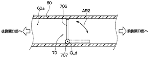
- FIG. 10 is a cross-sectional view of the air guide duct 60 and the on-off valve 70 cut along a cross section corresponding to the VI-VI cross section of FIG. 3 in the present embodiment, and corresponds to FIG. 7 of the first embodiment.
- the air guide duct 60 is not formed with an opening hole 60 f (see FIG. 7), and the opening / closing valve 70 is replaced with a rotating door 701 and a door rotating shaft 702, and a film door 705. have. These points are different from the first embodiment.
- the actuator 703 is not shown, and the same applies to FIGS. 11 and 12 described later.
- the film door 705 of the opening / closing valve 70 has a sheet shape. And the film door 705 increases / decreases the opening degree of the flow path 60a in a duct by slidingly moving like arrow AR1. For example, in order to slide the film door 705, the side edge of the film door 705 extending in the sliding movement direction is guided by the air guide duct 60.
- the film door 705 in a state where the opening degree of the duct internal flow path 60 a is minimized within the movable range of the film door 705 is represented by a solid line, and the opening degree of the duct internal flow path 60 a is maximized.
- the film door 705 is represented by a two-dot chain line.
- FIG. 11 is a cross-sectional view of the air duct 60 and the opening / closing valve 70 cut along a cross-section corresponding to the VI-VI cross-section of FIG. 3 in the present embodiment, and corresponds to FIG. 7 of the first embodiment.
- the air guide duct 60 is not formed with an opening hole 60f (see FIG. 7), and the opening / closing valve 70 is replaced with the rotating door 701 and the door rotating shaft 702 in FIG. 11 has a pivot door 706 and a door pivot shaft 707 in FIG.
- the turning door 706 of the opening / closing valve 70 has a plate shape and is accommodated in the air guide duct 60.
- the door rotation shaft 707 has, for example, a cylindrical shape, and is disposed in the duct inner flow path 60a so as to be biased toward one of the directions intersecting the air flow direction in the duct inner flow path 60a.
- the rotating door 706 is provided in one of the air guide ducts 60 in the radial direction with respect to the door axis line CLd in the direction intersecting the duct flow path 60a. That is, the door axis line CLd is the center line of the door rotation shaft 707, and the rotation door 706 is connected to the door rotation shaft 707 at the side edge of the rotation door 706.
- Rotating door 706 configured in this manner rotates like AR2 around door axis CLd in air guide duct 60, thereby increasing or decreasing the opening degree of duct internal flow path 60a.
- the rotating door 706 in a state where the opening of the duct internal flow path 60a is minimized within the movable range of the rotating door 706 is represented by a solid line, and the opening of the duct internal flow path 60a is maximized.
- the rotating door 706 in the state is represented by a two-dot chain line.
- FIG. 12 is a cross-sectional view of the present embodiment in which the air duct 60 and the opening / closing valve 70 are cut along a cross-section corresponding to the VI-VI cross-section of FIG. 3, and corresponds to FIG. 7 of the first embodiment. .
- the air guide duct 60 is not formed with an opening hole 60f (see FIG. 7), and the opening / closing valve 70 is replaced with the rotating door 701 and the door rotating shaft 702 of FIG. 12 has a pivot door 708 and a door pivot shaft 709 in FIG. These points are different from the first embodiment.
- the turning door 708 of the opening / closing valve 70 has a plate shape and is accommodated in the air guide duct 60.
- the door rotation shaft 709 has, for example, a cylindrical shape, and is disposed in the duct inner passage 60a at a central portion in a direction intersecting the air flow direction in the duct inner passage 60a.
- the rotating door 708 is provided in the air guide duct 60 from one side to the other side in the radial direction with respect to the door axis line CLd in a direction intersecting the duct flow path 60a. That is, the door axis line CLd is the center line of the door rotation shaft 709, and the rotation door 708 is connected to the door rotation shaft 709 at the central portion of the rotation door 708.
- Rotating door 708 configured as described above rotates like AR3 around door axis CLd in air guide duct 60, thereby increasing or decreasing the opening degree of duct internal flow path 60a.
- the rotating door 708 in a state where the opening of the duct internal passage 60a is minimized within the movable range of the rotating door 708 is indicated by a solid line, and the opening of the duct internal passage 60a is maximized.
- the rotating door 708 in the state is represented by a two-dot chain line.
- the engine room opening 2 is formed in the front grill 4 of the automobile 12, but is not limited thereto, and is formed, for example, in the lower front surface of the front bumper of the automobile 12. There is no problem.
- the cooling module 10 includes the radiator 30 as an engine cooling heat exchanger. Instead, an oil cooler that cools engine oil as a heat medium is engine-cooled. It may be provided as a heat exchanger for use.
- the air guide duct 60 is disposed on the upper side of the traveling engine 16 in the engine room 14, but may be disposed at a position other than the upper side of the traveling engine 16. Absent.
- the engine room opening 2 is provided in front of the vehicle with respect to the radiator 30.
- the engine room opening 2 is offset in the vehicle width direction DR2 with respect to the radiator 30. It may be provided at a different position.
- the exhaust manifold 18 is disposed in the engine room 14 at the rear of the vehicle with respect to the traveling engine 16, but at a position other than the rear of the vehicle with respect to the traveling engine 16. It may be arranged.
- the electric fan 40 is described as being an axial flow fan, for example, but may be a fan other than the axial flow fan, for example, a centrifugal fan.
- the capacitor 20, the radiator 30, and the electric fan 40 are arranged in the order of the capacitor 20, the radiator 30, and the electric fan 40 from the front of the vehicle. It's okay.
- the opening / closing valve 70 is provided on the way from the front opening 61 to the rear opening 62 of the air duct 60, but this is an example.
- the opening / closing valve 70 is provided in the front opening 61 or the rear opening 62 of the air guide duct 60.
Landscapes
- Engineering & Computer Science (AREA)
- Chemical & Material Sciences (AREA)
- Combustion & Propulsion (AREA)
- Mechanical Engineering (AREA)
- General Engineering & Computer Science (AREA)
- Transportation (AREA)
- Cooling, Air Intake And Gas Exhaust, And Fuel Tank Arrangements In Propulsion Units (AREA)
Abstract
Description
走行用エンジンが配置されるエンジンルームの車両前方にて開口したエンジンルーム開口部からエンジンルーム内へ空気が流入する自動車に適用される導風ユニットであって、
空調装置の放熱器と走行用エンジンを冷却するためのエンジン冷却用熱交換器と送風機とが固定され、エンジンルーム開口部を経て放熱器およびエンジン冷却用熱交換器を通過する空気を案内し、通風孔が形成されたシュラウドと、
通風孔にてシュラウドに接続されその通風孔を通して開口する第1開口部とエンジンルーム内のうち走行用エンジンに対する車両後方に開口する第2開口部とを有し、第1開口部と第2開口部との間に空気を流すダクト内流路を形成する導風ダクトと、
その導風ダクトに設けられ、ダクト内流路の開度を増減するバルブ部とを備えている。
図1は、本実施形態における冷却モジュール10の全体構成を車両上側から視た模式図である。図1の矢印DR1、DR2および後述する図2の矢印DR3は、冷却モジュール10が搭載された車両12の向きを示す。すなわち、図1の両端矢印DR1は車両前後方向DR1を示し、両端矢印DR2は車両左右方向DR2すなわち車両幅方向DR2を示し、図2の両端矢印DR3は車両上下方向DR3を示している。
次に、第2実施形態について説明する。本実施形態では、前述の第1実施形態と異なる点を主として説明する。また、前述の実施形態と同一または均等な部分については省略または簡略化して説明する。後述の第3実施形態以降でも同様である。
次に、第3実施形態について説明する。本実施形態では、前述の第1実施形態と異なる点を主として説明する。
次に、第4実施形態について説明する。本実施形態では、前述の第1実施形態と異なる点を主として説明する。
次に、第5実施形態について説明する。本実施形態では、前述の第1実施形態と異なる点を主として説明する。
(1)上述の各実施形態において、エンジンルーム開口部2は自動車12のフロントグリル4に形成されているが、それに限らず例えば、自動車12のフロントバンパーの下側前面に開口して形成されていても差し支えない。
Claims (11)
- 走行用エンジン(16)が配置されるエンジンルーム(14)の車両前方にて開口したエンジンルーム開口部(2)から前記エンジンルーム内へ空気が流入する自動車(12)に適用される導風ユニットであって、
空調装置の放熱器(20)と前記走行用エンジンを冷却するためのエンジン冷却用熱交換器(30)と送風機(40)とが固定され、前記エンジンルーム開口部を経て前記放熱器および前記エンジン冷却用熱交換器を通過する空気を案内し、通風孔(50b)が形成されたシュラウド(50)と、
前記通風孔にて前記シュラウドに接続され該通風孔を通して開口する第1開口部(61)と前記エンジンルーム内のうち前記走行用エンジンに対する車両後方に開口する第2開口部(62)とを有し、前記第1開口部と前記第2開口部との間に空気を流すダクト内流路(60a)を形成する導風ダクト(60)と、
該導風ダクトに設けられ、前記ダクト内流路の開度を増減するバルブ部(70)とを備えている導風ユニット。 - 前記バルブ部は、前記導風ダクトの前記第1開口部から前記第2開口部へ至る途中に設けられている請求項1に記載の導風ユニット。
- 前記導風ダクトには、該導風ダクトの前記第1開口部から前記第2開口部へ至る途中に設けられ前記ダクト内流路を前記導風ダクトの外部へ連通させる開口孔(60f)が形成され、
前記ダクト内流路は、前記導風ダクトのうち前記開口孔が形成された孔形成部位(602)と前記第2開口部との間の第2開口側流路(60c)を含み、
前記バルブ部は、前記ダクト内流路の開度を減少させるほど、前記第2開口側流路に対する前記開口孔の開度を増大させる請求項2に記載の導風ユニット。 - 前記バルブ部は、前記導風ダクト内で回動して前記開口孔を前記導風ダクトの内側から閉じる回動ドア(701)を有し、
該回動ドアは、前記開口孔に対して前記第1開口部側に偏った位置を通り前記ダクト内流路に交差する向きの軸線(CLd)まわりに回動する請求項3に記載の導風ユニット。 - 前記バルブ部は、前記導風ダクト内で回動して前記開口孔を前記導風ダクトの内側から閉じる回動ドア(701)を有し、
該回動ドアは前記導風ダクトとは別部品として構成され、
前記導風ダクトは、前記回動ドアに連結され該回動ドアを前記軸線まわりに回動可能に支持する連結部(601)を有している請求項3に記載の導風ユニット。 - 前記バルブ部は、前記導風ダクト内で回動して前記開口孔を前記導風ダクトの内側から閉じる回動ドア(701)を有し、
該回動ドアは、
前記導風ダクトに連結され可撓性を有する可撓部(704)を、前記回動ドアの周縁部分の一部に有し、
前記可撓部を介して前記導風ダクトと一体に構成され、
前記可撓部が撓むことにより回動する請求項3に記載の導風ユニット。 - 前記導風ダクトは、前記ダクト内流路に面する流路壁面(603)を有し、
前記回動ドアは、該回動ドアの可動範囲内で前記ダクト内流路の開度を最小にしたときに前記流路壁面に接触する壁面接触部(701b)を有し、
該壁面接触部は弾力性を有している請求項4ないし6のいずれか1つに記載の導風ユニット。 - 前記バルブ部は、シート状のフィルムドア(705)を有し、
該フィルムドアは、スライド移動することにより前記ダクト内流路の開度を増減する請求項1または2に記載の導風ユニット。 - 前記バルブ部は、前記導風ダクト内に収容され該導風ダクト内で回動する板状の回動ドア(706)を有し、
該回動ドアは、前記ダクト内流路に交差する向きの軸線(CLd)に対する径方向の一方に設けられ、該軸線まわりに回動することにより前記ダクト内流路の開度を増減する請求項1または2に記載の導風ユニット。 - 前記バルブ部は、前記導風ダクト内に収容され該導風ダクト内で回動する板状の回動ドア(708)を有し、
該回動ドアは、前記ダクト内流路に交差する向きの軸線(CLd)に対する径方向の一方から他方にわたって設けられ、該軸線まわりに回動することにより前記ダクト内流路の開度を増減する請求項1または2に記載の導風ユニット。 - 請求項1ないし10のいずれか1つに記載の導風ユニット(50、60、70)と、前記エンジン冷却用熱交換器と、前記送風機と、前記放熱器とを備えた冷却モジュール。
Priority Applications (3)
| Application Number | Priority Date | Filing Date | Title |
|---|---|---|---|
| JP2017528641A JP6447730B2 (ja) | 2015-07-10 | 2016-07-07 | 導風ユニットおよび冷却モジュール |
| US15/740,391 US10814717B2 (en) | 2015-07-10 | 2016-07-07 | Air guiding unit and cooling module |
| DE112016003129.7T DE112016003129T5 (de) | 2015-07-10 | 2016-07-07 | Luftleitungs-Einheit und Kühlmodul |
Applications Claiming Priority (2)
| Application Number | Priority Date | Filing Date | Title |
|---|---|---|---|
| JP2015138450 | 2015-07-10 | ||
| JP2015-138450 | 2015-07-10 |
Publications (1)
| Publication Number | Publication Date |
|---|---|
| WO2017010396A1 true WO2017010396A1 (ja) | 2017-01-19 |
Family
ID=57757329
Family Applications (1)
| Application Number | Title | Priority Date | Filing Date |
|---|---|---|---|
| PCT/JP2016/070131 Ceased WO2017010396A1 (ja) | 2015-07-10 | 2016-07-07 | 導風ユニットおよび冷却モジュール |
Country Status (4)
| Country | Link |
|---|---|
| US (1) | US10814717B2 (ja) |
| JP (1) | JP6447730B2 (ja) |
| DE (1) | DE112016003129T5 (ja) |
| WO (1) | WO2017010396A1 (ja) |
Cited By (1)
| Publication number | Priority date | Publication date | Assignee | Title |
|---|---|---|---|---|
| CN108343506A (zh) * | 2018-05-02 | 2018-07-31 | 隆鑫通用动力股份有限公司 | 一种发电机组 |
Families Citing this family (7)
| Publication number | Priority date | Publication date | Assignee | Title |
|---|---|---|---|---|
| JP6447730B2 (ja) * | 2015-07-10 | 2019-01-09 | 株式会社デンソー | 導風ユニットおよび冷却モジュール |
| JP7232090B2 (ja) * | 2019-03-19 | 2023-03-02 | 株式会社Subaru | 車両 |
| CN111267605B (zh) * | 2020-03-31 | 2023-03-28 | 重庆长安汽车股份有限公司 | 一种发动机舱引流结构 |
| US11555291B2 (en) * | 2020-04-06 | 2023-01-17 | Deere & Company | Self-propelled work vehicle and method implementing perception inputs for cooling fan control operations |
| JP2022032788A (ja) * | 2020-08-14 | 2022-02-25 | 日本電気株式会社 | 冷却装置、冷却システム、および冷却方法 |
| DE102021102468B3 (de) | 2021-02-03 | 2022-07-07 | Audi Aktiengesellschaft | Luftführungsanordnung für ein Fahrzeug |
| FR3141390A1 (fr) * | 2022-10-28 | 2024-05-03 | Psa Automobiles Sa | Système de gestion d’entrée d’air pour véhicule automobile et véhicule automobile équipé d’un tel système |
Citations (2)
| Publication number | Priority date | Publication date | Assignee | Title |
|---|---|---|---|---|
| JPH11321347A (ja) * | 1998-03-13 | 1999-11-24 | Denso Corp | 車両用冷却装置 |
| JP2007099194A (ja) * | 2005-10-07 | 2007-04-19 | Toyota Motor Corp | 車両用冷却システムの導風構造 |
Family Cites Families (25)
| Publication number | Priority date | Publication date | Assignee | Title |
|---|---|---|---|---|
| JPS59110326U (ja) * | 1983-01-18 | 1984-07-25 | トヨタ自動車株式会社 | 自動車エンジンル−ム内部品の冷却装置 |
| US4971172A (en) * | 1989-06-30 | 1990-11-20 | Navistar International Transportation Corp. | Truck hood engine air induction system |
| AU642787B2 (en) * | 1990-11-23 | 1993-10-28 | Nippondenso Co. Ltd. | Cooling system for a water cooled internal combustion engine for vehicle having an airconditioning apparatus |
| DE59108887D1 (de) * | 1991-08-30 | 1997-12-11 | Weinhold Wolfgang P M Sc Dipl | Kühlvorrichtung für einen Verbrennungsmotor in einem Kraftfahrzeug |
| JP2830788B2 (ja) * | 1995-08-25 | 1998-12-02 | トヨタ自動車株式会社 | エンジンルーム内の吸気冷却構造 |
| FR2782480B1 (fr) * | 1998-08-24 | 2000-10-20 | Solvay | Dispositif et procede d'evacuation des calories d'un compartiment |
| JP3646577B2 (ja) | 1999-07-29 | 2005-05-11 | トヨタ車体株式会社 | 車両のインタークーラ冷却用ダクト |
| JP2003083046A (ja) * | 2001-09-11 | 2003-03-19 | Honda Motor Co Ltd | エンジンの排気系冷却装置 |
| EP1348845A3 (en) * | 2002-03-26 | 2005-05-11 | Honda Giken Kogyo Kabushiki Kaisha | Engine cooling system for rear-engine vehicle |
| JP4126601B2 (ja) | 2002-09-30 | 2008-07-30 | 株式会社イノアックコーポレーション | 車両用ダクト |
| JP2005053464A (ja) * | 2003-07-24 | 2005-03-03 | Denso Corp | 車両の前端構造 |
| US6988574B2 (en) * | 2003-08-28 | 2006-01-24 | Jones Performance Products, Inc. | One-way air duct for engine compartment cooling |
| JP2007055274A (ja) * | 2005-08-22 | 2007-03-08 | Mazda Motor Corp | 車体前部構造 |
| JP2007083861A (ja) * | 2005-09-22 | 2007-04-05 | Nissan Motor Co Ltd | 車両用冷却装置 |
| JP4482538B2 (ja) | 2006-04-26 | 2010-06-16 | 本田技研工業株式会社 | 車両用フード構造 |
| US8186153B2 (en) * | 2009-05-01 | 2012-05-29 | Deere & Company | Engine compartment arrangement for cleaning diesel particulate filter |
| JP5131410B2 (ja) * | 2010-08-03 | 2013-01-30 | トヨタ自動車株式会社 | 車両用冷却構造 |
| KR101542992B1 (ko) * | 2014-05-08 | 2015-08-07 | 현대자동차 주식회사 | 자동차의 냉각 장치 |
| FR3022878B1 (fr) * | 2014-06-27 | 2018-04-13 | Compagnie Plastic Omnium | Face avant de vehicule automobile avec entree d'air centrale et sorties laterales |
| JP6380212B2 (ja) * | 2014-12-09 | 2018-08-29 | 株式会社デンソー | 冷却装置、および冷却モジュール |
| JP6447730B2 (ja) * | 2015-07-10 | 2019-01-09 | 株式会社デンソー | 導風ユニットおよび冷却モジュール |
| KR101713741B1 (ko) * | 2016-03-30 | 2017-03-08 | 현대자동차 주식회사 | 차량 엔진 룸 공기 유량 제어 시스템 및 그 제어 방법 |
| JP6311744B2 (ja) * | 2016-06-06 | 2018-04-18 | トヨタ自動車株式会社 | 空冷式燃料電池車 |
| US10479191B2 (en) * | 2017-12-19 | 2019-11-19 | Cnh Industrial America Llc | Cooling systems and methods for an agricultural harvester |
| JP2019147527A (ja) * | 2018-02-28 | 2019-09-05 | トヨタ自動車株式会社 | 車両前部構造 |
-
2016
- 2016-07-07 JP JP2017528641A patent/JP6447730B2/ja not_active Expired - Fee Related
- 2016-07-07 DE DE112016003129.7T patent/DE112016003129T5/de not_active Withdrawn
- 2016-07-07 WO PCT/JP2016/070131 patent/WO2017010396A1/ja not_active Ceased
- 2016-07-07 US US15/740,391 patent/US10814717B2/en not_active Expired - Fee Related
Patent Citations (2)
| Publication number | Priority date | Publication date | Assignee | Title |
|---|---|---|---|---|
| JPH11321347A (ja) * | 1998-03-13 | 1999-11-24 | Denso Corp | 車両用冷却装置 |
| JP2007099194A (ja) * | 2005-10-07 | 2007-04-19 | Toyota Motor Corp | 車両用冷却システムの導風構造 |
Cited By (2)
| Publication number | Priority date | Publication date | Assignee | Title |
|---|---|---|---|---|
| CN108343506A (zh) * | 2018-05-02 | 2018-07-31 | 隆鑫通用动力股份有限公司 | 一种发电机组 |
| CN108343506B (zh) * | 2018-05-02 | 2024-03-15 | 隆鑫通用动力股份有限公司 | 一种发电机组 |
Also Published As
| Publication number | Publication date |
|---|---|
| JP6447730B2 (ja) | 2019-01-09 |
| DE112016003129T5 (de) | 2018-03-22 |
| JPWO2017010396A1 (ja) | 2017-11-16 |
| US10814717B2 (en) | 2020-10-27 |
| US20180264932A1 (en) | 2018-09-20 |
Similar Documents
| Publication | Publication Date | Title |
|---|---|---|
| JP6447730B2 (ja) | 導風ユニットおよび冷却モジュール | |
| JP6380212B2 (ja) | 冷却装置、および冷却モジュール | |
| CN104203611B (zh) | 空气通路开闭装置 | |
| US9168811B2 (en) | Partial recirculation vehicle HVAC system | |
| US10794261B2 (en) | Cooling module | |
| WO2012114573A1 (ja) | 車両用空調装置 | |
| CN105517822A (zh) | 空调单元 | |
| CN106457975A (zh) | 空气吹出装置 | |
| JP2016097802A (ja) | エンジンルーム通風構造 | |
| US8425284B2 (en) | Heating ventilation and air conditioning case with honeycomb | |
| WO2017221460A1 (ja) | 空調装置 | |
| CN107249911A (zh) | 车辆用空调单元 | |
| CN107921861A (zh) | 冷却装置 | |
| JP4682443B2 (ja) | 車両用空調装置 | |
| JP4326235B2 (ja) | 車両用空気調和装置 | |
| JP2014061790A (ja) | 車両用空調装置 | |
| WO2007074878A1 (ja) | 空調装置 | |
| US20240093633A1 (en) | Vehicle cooling system | |
| JPH11180128A (ja) | 車両用空調装置 | |
| CN116601029A (zh) | 具有切向流涡轮机的用于电动或混合动力机动车辆的冷却模块 | |
| WO2018030378A1 (ja) | 車両の放熱器冷却システム、車両、及び車両の放熱器冷却方法 | |
| JP5527302B2 (ja) | 送風装置 | |
| JP2015003684A (ja) | 車両用空調装置 | |
| JP2018144501A (ja) | 導風ユニットおよび冷却モジュール | |
| JP2007276547A (ja) | 空気流通路切替え装置およびこれを備えた車両用空調装置 |
Legal Events
| Date | Code | Title | Description |
|---|---|---|---|
| 121 | Ep: the epo has been informed by wipo that ep was designated in this application |
Ref document number: 16824376 Country of ref document: EP Kind code of ref document: A1 |
|
| ENP | Entry into the national phase |
Ref document number: 2017528641 Country of ref document: JP Kind code of ref document: A |
|
| WWE | Wipo information: entry into national phase |
Ref document number: 15740391 Country of ref document: US |
|
| WWE | Wipo information: entry into national phase |
Ref document number: 112016003129 Country of ref document: DE |
|
| 122 | Ep: pct application non-entry in european phase |
Ref document number: 16824376 Country of ref document: EP Kind code of ref document: A1 |