WO2017006743A1 - 自動車の制御装置 - Google Patents
自動車の制御装置 Download PDFInfo
- Publication number
- WO2017006743A1 WO2017006743A1 PCT/JP2016/068024 JP2016068024W WO2017006743A1 WO 2017006743 A1 WO2017006743 A1 WO 2017006743A1 JP 2016068024 W JP2016068024 W JP 2016068024W WO 2017006743 A1 WO2017006743 A1 WO 2017006743A1
- Authority
- WO
- WIPO (PCT)
- Prior art keywords
- engine
- vehicle
- host vehicle
- acceleration
- control
- Prior art date
Links
Images


Classifications
-
- B—PERFORMING OPERATIONS; TRANSPORTING
- B60—VEHICLES IN GENERAL
- B60W—CONJOINT CONTROL OF VEHICLE SUB-UNITS OF DIFFERENT TYPE OR DIFFERENT FUNCTION; CONTROL SYSTEMS SPECIALLY ADAPTED FOR HYBRID VEHICLES; ROAD VEHICLE DRIVE CONTROL SYSTEMS FOR PURPOSES NOT RELATED TO THE CONTROL OF A PARTICULAR SUB-UNIT
- B60W10/00—Conjoint control of vehicle sub-units of different type or different function
- B60W10/02—Conjoint control of vehicle sub-units of different type or different function including control of driveline clutches
-
- B—PERFORMING OPERATIONS; TRANSPORTING
- B60—VEHICLES IN GENERAL
- B60W—CONJOINT CONTROL OF VEHICLE SUB-UNITS OF DIFFERENT TYPE OR DIFFERENT FUNCTION; CONTROL SYSTEMS SPECIALLY ADAPTED FOR HYBRID VEHICLES; ROAD VEHICLE DRIVE CONTROL SYSTEMS FOR PURPOSES NOT RELATED TO THE CONTROL OF A PARTICULAR SUB-UNIT
- B60W10/00—Conjoint control of vehicle sub-units of different type or different function
- B60W10/04—Conjoint control of vehicle sub-units of different type or different function including control of propulsion units
- B60W10/06—Conjoint control of vehicle sub-units of different type or different function including control of propulsion units including control of combustion engines
-
- B—PERFORMING OPERATIONS; TRANSPORTING
- B60—VEHICLES IN GENERAL
- B60W—CONJOINT CONTROL OF VEHICLE SUB-UNITS OF DIFFERENT TYPE OR DIFFERENT FUNCTION; CONTROL SYSTEMS SPECIALLY ADAPTED FOR HYBRID VEHICLES; ROAD VEHICLE DRIVE CONTROL SYSTEMS FOR PURPOSES NOT RELATED TO THE CONTROL OF A PARTICULAR SUB-UNIT
- B60W30/00—Purposes of road vehicle drive control systems not related to the control of a particular sub-unit, e.g. of systems using conjoint control of vehicle sub-units, or advanced driver assistance systems for ensuring comfort, stability and safety or drive control systems for propelling or retarding the vehicle
- B60W30/08—Active safety systems predicting or avoiding probable or impending collision or attempting to minimise its consequences
- B60W30/09—Taking automatic action to avoid collision, e.g. braking and steering
-
- B—PERFORMING OPERATIONS; TRANSPORTING
- B60—VEHICLES IN GENERAL
- B60W—CONJOINT CONTROL OF VEHICLE SUB-UNITS OF DIFFERENT TYPE OR DIFFERENT FUNCTION; CONTROL SYSTEMS SPECIALLY ADAPTED FOR HYBRID VEHICLES; ROAD VEHICLE DRIVE CONTROL SYSTEMS FOR PURPOSES NOT RELATED TO THE CONTROL OF A PARTICULAR SUB-UNIT
- B60W30/00—Purposes of road vehicle drive control systems not related to the control of a particular sub-unit, e.g. of systems using conjoint control of vehicle sub-units, or advanced driver assistance systems for ensuring comfort, stability and safety or drive control systems for propelling or retarding the vehicle
- B60W30/10—Path keeping
-
- B—PERFORMING OPERATIONS; TRANSPORTING
- B60—VEHICLES IN GENERAL
- B60W—CONJOINT CONTROL OF VEHICLE SUB-UNITS OF DIFFERENT TYPE OR DIFFERENT FUNCTION; CONTROL SYSTEMS SPECIALLY ADAPTED FOR HYBRID VEHICLES; ROAD VEHICLE DRIVE CONTROL SYSTEMS FOR PURPOSES NOT RELATED TO THE CONTROL OF A PARTICULAR SUB-UNIT
- B60W30/00—Purposes of road vehicle drive control systems not related to the control of a particular sub-unit, e.g. of systems using conjoint control of vehicle sub-units, or advanced driver assistance systems for ensuring comfort, stability and safety or drive control systems for propelling or retarding the vehicle
- B60W30/18—Propelling the vehicle
- B60W30/18009—Propelling the vehicle related to particular drive situations
- B60W30/18072—Coasting
-
- F—MECHANICAL ENGINEERING; LIGHTING; HEATING; WEAPONS; BLASTING
- F02—COMBUSTION ENGINES; HOT-GAS OR COMBUSTION-PRODUCT ENGINE PLANTS
- F02D—CONTROLLING COMBUSTION ENGINES
- F02D29/00—Controlling engines, such controlling being peculiar to the devices driven thereby, the devices being other than parts or accessories essential to engine operation, e.g. controlling of engines by signals external thereto
- F02D29/02—Controlling engines, such controlling being peculiar to the devices driven thereby, the devices being other than parts or accessories essential to engine operation, e.g. controlling of engines by signals external thereto peculiar to engines driving vehicles; peculiar to engines driving variable pitch propellers
-
- F—MECHANICAL ENGINEERING; LIGHTING; HEATING; WEAPONS; BLASTING
- F02—COMBUSTION ENGINES; HOT-GAS OR COMBUSTION-PRODUCT ENGINE PLANTS
- F02N—STARTING OF COMBUSTION ENGINES; STARTING AIDS FOR SUCH ENGINES, NOT OTHERWISE PROVIDED FOR
- F02N11/00—Starting of engines by means of electric motors
- F02N11/08—Circuits or control means specially adapted for starting of engines
- F02N11/0814—Circuits or control means specially adapted for starting of engines comprising means for controlling automatic idle-start-stop
- F02N11/0818—Conditions for starting or stopping the engine or for deactivating the idle-start-stop mode
- F02N11/0833—Vehicle conditions
- F02N11/0837—Environmental conditions thereof, e.g. traffic, weather or road conditions
-
- F—MECHANICAL ENGINEERING; LIGHTING; HEATING; WEAPONS; BLASTING
- F16—ENGINEERING ELEMENTS AND UNITS; GENERAL MEASURES FOR PRODUCING AND MAINTAINING EFFECTIVE FUNCTIONING OF MACHINES OR INSTALLATIONS; THERMAL INSULATION IN GENERAL
- F16D—COUPLINGS FOR TRANSMITTING ROTATION; CLUTCHES; BRAKES
- F16D48/00—External control of clutches
- F16D48/02—Control by fluid pressure
-
- B—PERFORMING OPERATIONS; TRANSPORTING
- B60—VEHICLES IN GENERAL
- B60W—CONJOINT CONTROL OF VEHICLE SUB-UNITS OF DIFFERENT TYPE OR DIFFERENT FUNCTION; CONTROL SYSTEMS SPECIALLY ADAPTED FOR HYBRID VEHICLES; ROAD VEHICLE DRIVE CONTROL SYSTEMS FOR PURPOSES NOT RELATED TO THE CONTROL OF A PARTICULAR SUB-UNIT
- B60W30/00—Purposes of road vehicle drive control systems not related to the control of a particular sub-unit, e.g. of systems using conjoint control of vehicle sub-units, or advanced driver assistance systems for ensuring comfort, stability and safety or drive control systems for propelling or retarding the vehicle
- B60W30/18—Propelling the vehicle
- B60W30/18009—Propelling the vehicle related to particular drive situations
- B60W30/18072—Coasting
- B60W2030/18081—With torque flow from driveshaft to engine, i.e. engine being driven by vehicle
-
- B—PERFORMING OPERATIONS; TRANSPORTING
- B60—VEHICLES IN GENERAL
- B60W—CONJOINT CONTROL OF VEHICLE SUB-UNITS OF DIFFERENT TYPE OR DIFFERENT FUNCTION; CONTROL SYSTEMS SPECIALLY ADAPTED FOR HYBRID VEHICLES; ROAD VEHICLE DRIVE CONTROL SYSTEMS FOR PURPOSES NOT RELATED TO THE CONTROL OF A PARTICULAR SUB-UNIT
- B60W30/00—Purposes of road vehicle drive control systems not related to the control of a particular sub-unit, e.g. of systems using conjoint control of vehicle sub-units, or advanced driver assistance systems for ensuring comfort, stability and safety or drive control systems for propelling or retarding the vehicle
- B60W30/18—Propelling the vehicle
- B60W30/18009—Propelling the vehicle related to particular drive situations
- B60W30/18072—Coasting
- B60W2030/1809—Without torque flow between driveshaft and engine, e.g. with clutch disengaged or transmission in neutral
-
- B—PERFORMING OPERATIONS; TRANSPORTING
- B60—VEHICLES IN GENERAL
- B60W—CONJOINT CONTROL OF VEHICLE SUB-UNITS OF DIFFERENT TYPE OR DIFFERENT FUNCTION; CONTROL SYSTEMS SPECIALLY ADAPTED FOR HYBRID VEHICLES; ROAD VEHICLE DRIVE CONTROL SYSTEMS FOR PURPOSES NOT RELATED TO THE CONTROL OF A PARTICULAR SUB-UNIT
- B60W2540/00—Input parameters relating to occupants
- B60W2540/10—Accelerator pedal position
-
- B—PERFORMING OPERATIONS; TRANSPORTING
- B60—VEHICLES IN GENERAL
- B60W—CONJOINT CONTROL OF VEHICLE SUB-UNITS OF DIFFERENT TYPE OR DIFFERENT FUNCTION; CONTROL SYSTEMS SPECIALLY ADAPTED FOR HYBRID VEHICLES; ROAD VEHICLE DRIVE CONTROL SYSTEMS FOR PURPOSES NOT RELATED TO THE CONTROL OF A PARTICULAR SUB-UNIT
- B60W2540/00—Input parameters relating to occupants
- B60W2540/12—Brake pedal position
-
- B—PERFORMING OPERATIONS; TRANSPORTING
- B60—VEHICLES IN GENERAL
- B60W—CONJOINT CONTROL OF VEHICLE SUB-UNITS OF DIFFERENT TYPE OR DIFFERENT FUNCTION; CONTROL SYSTEMS SPECIALLY ADAPTED FOR HYBRID VEHICLES; ROAD VEHICLE DRIVE CONTROL SYSTEMS FOR PURPOSES NOT RELATED TO THE CONTROL OF A PARTICULAR SUB-UNIT
- B60W2552/00—Input parameters relating to infrastructure
- B60W2552/15—Road slope
-
- B—PERFORMING OPERATIONS; TRANSPORTING
- B60—VEHICLES IN GENERAL
- B60W—CONJOINT CONTROL OF VEHICLE SUB-UNITS OF DIFFERENT TYPE OR DIFFERENT FUNCTION; CONTROL SYSTEMS SPECIALLY ADAPTED FOR HYBRID VEHICLES; ROAD VEHICLE DRIVE CONTROL SYSTEMS FOR PURPOSES NOT RELATED TO THE CONTROL OF A PARTICULAR SUB-UNIT
- B60W2552/00—Input parameters relating to infrastructure
- B60W2552/30—Road curve radius
-
- B—PERFORMING OPERATIONS; TRANSPORTING
- B60—VEHICLES IN GENERAL
- B60W—CONJOINT CONTROL OF VEHICLE SUB-UNITS OF DIFFERENT TYPE OR DIFFERENT FUNCTION; CONTROL SYSTEMS SPECIALLY ADAPTED FOR HYBRID VEHICLES; ROAD VEHICLE DRIVE CONTROL SYSTEMS FOR PURPOSES NOT RELATED TO THE CONTROL OF A PARTICULAR SUB-UNIT
- B60W2552/00—Input parameters relating to infrastructure
- B60W2552/40—Coefficient of friction
-
- B—PERFORMING OPERATIONS; TRANSPORTING
- B60—VEHICLES IN GENERAL
- B60W—CONJOINT CONTROL OF VEHICLE SUB-UNITS OF DIFFERENT TYPE OR DIFFERENT FUNCTION; CONTROL SYSTEMS SPECIALLY ADAPTED FOR HYBRID VEHICLES; ROAD VEHICLE DRIVE CONTROL SYSTEMS FOR PURPOSES NOT RELATED TO THE CONTROL OF A PARTICULAR SUB-UNIT
- B60W2554/00—Input parameters relating to objects
- B60W2554/80—Spatial relation or speed relative to objects
-
- B—PERFORMING OPERATIONS; TRANSPORTING
- B60—VEHICLES IN GENERAL
- B60W—CONJOINT CONTROL OF VEHICLE SUB-UNITS OF DIFFERENT TYPE OR DIFFERENT FUNCTION; CONTROL SYSTEMS SPECIALLY ADAPTED FOR HYBRID VEHICLES; ROAD VEHICLE DRIVE CONTROL SYSTEMS FOR PURPOSES NOT RELATED TO THE CONTROL OF A PARTICULAR SUB-UNIT
- B60W2720/00—Output or target parameters relating to overall vehicle dynamics
- B60W2720/10—Longitudinal speed
- B60W2720/106—Longitudinal acceleration
-
- F—MECHANICAL ENGINEERING; LIGHTING; HEATING; WEAPONS; BLASTING
- F02—COMBUSTION ENGINES; HOT-GAS OR COMBUSTION-PRODUCT ENGINE PLANTS
- F02N—STARTING OF COMBUSTION ENGINES; STARTING AIDS FOR SUCH ENGINES, NOT OTHERWISE PROVIDED FOR
- F02N2200/00—Parameters used for control of starting apparatus
- F02N2200/12—Parameters used for control of starting apparatus said parameters being related to the vehicle exterior
- F02N2200/121—Atmospheric pressure, e.g. for determination of geodetic height
-
- F—MECHANICAL ENGINEERING; LIGHTING; HEATING; WEAPONS; BLASTING
- F02—COMBUSTION ENGINES; HOT-GAS OR COMBUSTION-PRODUCT ENGINE PLANTS
- F02N—STARTING OF COMBUSTION ENGINES; STARTING AIDS FOR SUCH ENGINES, NOT OTHERWISE PROVIDED FOR
- F02N2200/00—Parameters used for control of starting apparatus
- F02N2200/12—Parameters used for control of starting apparatus said parameters being related to the vehicle exterior
- F02N2200/123—Information about vehicle position, e.g. from navigation systems or GPS signals
-
- F—MECHANICAL ENGINEERING; LIGHTING; HEATING; WEAPONS; BLASTING
- F02—COMBUSTION ENGINES; HOT-GAS OR COMBUSTION-PRODUCT ENGINE PLANTS
- F02N—STARTING OF COMBUSTION ENGINES; STARTING AIDS FOR SUCH ENGINES, NOT OTHERWISE PROVIDED FOR
- F02N2200/00—Parameters used for control of starting apparatus
- F02N2200/12—Parameters used for control of starting apparatus said parameters being related to the vehicle exterior
- F02N2200/124—Information about road conditions, e.g. road inclination or surface
-
- F—MECHANICAL ENGINEERING; LIGHTING; HEATING; WEAPONS; BLASTING
- F02—COMBUSTION ENGINES; HOT-GAS OR COMBUSTION-PRODUCT ENGINE PLANTS
- F02N—STARTING OF COMBUSTION ENGINES; STARTING AIDS FOR SUCH ENGINES, NOT OTHERWISE PROVIDED FOR
- F02N2200/00—Parameters used for control of starting apparatus
- F02N2200/12—Parameters used for control of starting apparatus said parameters being related to the vehicle exterior
- F02N2200/125—Information about other vehicles, traffic lights or traffic congestion
-
- Y—GENERAL TAGGING OF NEW TECHNOLOGICAL DEVELOPMENTS; GENERAL TAGGING OF CROSS-SECTIONAL TECHNOLOGIES SPANNING OVER SEVERAL SECTIONS OF THE IPC; TECHNICAL SUBJECTS COVERED BY FORMER USPC CROSS-REFERENCE ART COLLECTIONS [XRACs] AND DIGESTS
- Y02—TECHNOLOGIES OR APPLICATIONS FOR MITIGATION OR ADAPTATION AGAINST CLIMATE CHANGE
- Y02T—CLIMATE CHANGE MITIGATION TECHNOLOGIES RELATED TO TRANSPORTATION
- Y02T10/00—Road transport of goods or passengers
- Y02T10/10—Internal combustion engine [ICE] based vehicles
- Y02T10/40—Engine management systems
-
- Y—GENERAL TAGGING OF NEW TECHNOLOGICAL DEVELOPMENTS; GENERAL TAGGING OF CROSS-SECTIONAL TECHNOLOGIES SPANNING OVER SEVERAL SECTIONS OF THE IPC; TECHNICAL SUBJECTS COVERED BY FORMER USPC CROSS-REFERENCE ART COLLECTIONS [XRACs] AND DIGESTS
- Y02—TECHNOLOGIES OR APPLICATIONS FOR MITIGATION OR ADAPTATION AGAINST CLIMATE CHANGE
- Y02T—CLIMATE CHANGE MITIGATION TECHNOLOGIES RELATED TO TRANSPORTATION
- Y02T10/00—Road transport of goods or passengers
- Y02T10/60—Other road transportation technologies with climate change mitigation effect
Definitions
- the present invention relates to an automobile control device, and more particularly to an automobile control device having an automatic stop and restart function for automatically stopping and restarting an engine.
- engine stop and inertia traveling control This can be expected to improve fuel consumption because the engine can be stopped and the vehicle speed can be maintained for a long time without depressing the accelerator pedal.
- Patent Document 1 Japanese Patent Application Laid-Open No. 2007-291919
- Patent Document 1 when the distance between the host vehicle and the preceding vehicle is greater than the maximum distance between the host vehicle and the host vehicle is traveling down a slope, the host vehicle is not generated without starting generation of driving force. It is described that the coasting is carried out.
- An object of the present invention is to provide a novel automobile control apparatus that can reduce the number of stops and restarts while performing engine stop and inertial running control.
- the feature of the present invention is that when the probability of restarting the engine is high under a state where the engine is stopped and inertial running control is performed, only the clutch is disengaged and the engine continues to be driven at a predetermined rotational speed. is there.
- the predetermined rotational speed is preferably an idle rotational speed, which can reduce fuel consumption.
- the clutch is disengaged and coasting is performed, and the engine is in a driving state. Therefore, it is not necessary to restart the engine, and the number of restarts can be suppressed.
- FIG. 1 is a configuration diagram showing a schematic configuration of a vehicle to which the present invention is applied. It is a block diagram which shows the internal structure of the control apparatus of the motor vehicle shown in FIG. It is a flowchart which shows the specific control flow of the control apparatus of the motor vehicle which becomes the 1st Example of this invention. It is explanatory drawing explaining the state in which the own vehicle is located in front of the downward slope, and the preceding vehicle has entered the traveling road on the downward slope. It is explanatory drawing explaining the state in which both the own vehicle and a preceding vehicle have approached the downhill traveling path.
- FIG. 6 is an explanatory diagram for explaining a state in which the host vehicle is positioned in front of the vicinity of the curvature change area of the travel path and the preceding vehicle enters the travel path of the curvature change area, according to the second embodiment of the present invention. is there. It is explanatory drawing explaining the state which both the own vehicle and the preceding vehicle got out of the curvature change area
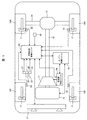
- FIG. 1 shows a schematic configuration of a drive system of an automobile, an in-cylinder injection engine 10 as a driving power source, an automatic transmission 11 that adjusts the rotational force of the engine 10 by a transmission mechanism, and an automatic transmission.
- a front wheel 15F steered by the device and a friction brake 17 provided on each of the wheels 15F and 15R are provided.
- a clutch mechanism (not shown) is interposed between the engine 10 and the automatic transmission 11, and by rotating the clutch, the rotation of the engine 10 is transmitted to the automatic transmission 11 and the clutch is disconnected. Thus, the rotation of the engine 10 is not transmitted to the automatic transmission 11.
- the engine 10 is controlled by an engine control unit 18 and the automatic transmission 11 is controlled by a transmission control unit 19.
- the above-described clutch mechanism is also controlled by the transmission control unit 19.
- the engine control unit 18 and the transmission control unit 19 are communicated with each other via a communication line.
- the engine control unit 18 and the transmission control unit 19 are communicated with the vehicle integrated control unit 20 via a communication line.
- the vehicle integrated control unit 20 is depressed by an external recognition means 21, a wheel speed sensor 22 that detects the rotational speed of the wheels 15F and 15R, an accelerator pedal sensor 24 that detects that the accelerator pedal 23 is depressed, and a brake pedal 25.
- Information from a brake pedal sensor 26, a direction indicator signal 27, a gyro sensor 28, and the like are detected.
- each control unit incorporating a microcomputer such as a vehicle integrated control unit 20, an engine control unit 18, a transmission control unit 19 and the like is configured to transfer control information through a communication line.
- each control unit and actuators and devices including sensors to be described later can exchange control information via an in-vehicle LAN (CAN).
- CAN in-vehicle LAN
- the outside world recognizing means 21 has a control unit part with a built-in microcomputer, and the control unit part, based on the captured image, the relative speed between the preceding vehicle ahead of the host vehicle and the host vehicle, the host vehicle Various information such as the distance between the vehicle ahead of the vehicle, obstacles, oncoming vehicles, etc. (vehicle distance, etc.), the height in the vertical direction from the road surface of the road of the preceding vehicle, and the difference in lateral position Then, the calculation result is transmitted to the vehicle integrated control unit 20.
- one or more of laser radar, millimeter wave radar, mono camera, stereo camera, etc. may be used in combination. Moreover, you may acquire using road-to-vehicle communication or vehicle-to-vehicle communication. In this embodiment, a stereo camera is used.
- the vehicle integrated control unit 20 is depressed by four wheel speed sensors 22 for detecting the rotational speeds of the wheels 15F and 15R, an accelerator pedal sensor 24 for detecting that the accelerator pedal 23 is depressed, and a brake pedal 25.
- Information from the brake pedal sensor 26, the direction indicator signal 27, the gyro sensor 28, and the like that detect this is also input.
- the engine control unit 18 includes an operation state of the engine 10 (for example, engine speed, intake air) from sensors provided in the engine 10. Various information representing the amount, throttle opening, in-cylinder pressure, etc.) or serving as a basis for obtaining them. Further, the engine control unit 18 transmits a predetermined drive signal to the fuel injection valve 29, the ignition unit 30 including an ignition coil, an ignition plug, and the like based on these pieces of information, the electric throttle valve 31, etc. , Quantity) control, ignition (energization angle, ignition timing) control, throttle opening control, and the like.
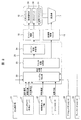
- the vehicle integrated control unit 20 includes a system determination unit 32, a clutch state determination unit 33, and an engine state determination unit 34 as related to the present embodiment.
- the system determination unit 32, the clutch state determination unit 33, and the engine state determination unit 34 function as automatic stop and restart means.
- the system determination unit 32 calculates the speed of the host vehicle and the depression amount of the accelerator pedal based on information from the four wheel speed sensors 22 and the accelerator pedal sensor 24. Further, the system determination unit 32 is based on information on the relative relationship (for example, relative speed, relative distance, etc.) with the preceding vehicle obtained from the accelerator pedal sensor 24, the direction indicator 27, the brake pedal sensor 26, and the external world recognition sensor 21. Thus, a deceleration required for promptly avoiding a collision of the host vehicle (hereinafter referred to as a requested deceleration) is calculated. If this required deceleration is equal to or greater than a predetermined value (for example, a deceleration estimated to be generated by engine braking), it is determined that deceleration assist by engine braking is necessary.
- a predetermined value for example, a deceleration estimated to be generated by engine braking
- the probability that the acceleration of the host vehicle or the preceding vehicle changes is determined in a state where the accelerator pedal 23 and the brake pedal 25 of the host vehicle are not depressed.
- the probability means the degree of certainty.
- the acceleration of the host vehicle or the preceding vehicle may change due to other factors. In short, it is only necessary to detect the event that the acceleration of the host vehicle or the preceding vehicle changes and determine the probability that the acceleration changes.
- the change in acceleration includes the case where the vehicle is decelerated.
- the clutch state determination unit 33 (1) determines that the accelerator pedal 23 is depressed, or (2) determines that deceleration assistance by engine braking is necessary, or (3) performs inertial running. In this case, when it is determined that the pedal-off continuation time is shorter than the pedal-off continuation time when engine braking is performed, a function for determining that the clutch engagement condition is satisfied is provided.
- the engine state determination unit 34 determines that the fuel stop condition is satisfied when the accelerator pedal 23 is not depressed and the clutch state determination unit 33 does not determine that the clutch is disengaged.
- the pedal-off duration is the fuel stop time
- the longer pedal-off duration in engine brake travel means that the fuel economy improvement effect is greater in engine brake travel than in fuel efficiency improvement due to coasting. Means.
- the engine state determination unit 34 turns off the pedal of the host vehicle when the system determination unit 51 determines that the accelerator pedal 23 and the brake pedal 25 are not depressed and the clutch state determination unit 33 determines that the clutch disengagement is permitted. The probability that the acceleration of the host vehicle or the preceding vehicle will change is determined. If it is determined that there is a high probability that the acceleration will change, the engine continues to burn with the clutch disengaged.
- the probability that the acceleration changes is considered to be high when the host vehicle and the preceding vehicle enter a downhill.
- the probability that the acceleration changes is determined.
- the transmission control unit 19 When a clutch disengagement command is transmitted from the clutch state determination unit 33, the transmission control unit 19 immediately disengages the clutch to reduce the deceleration of the host vehicle, and realizes the inertia running state.
- the clutch engagement is maintained or, if the clutch is disconnected, the engine rotation and the wheel rotation are synchronized and the clutch is immediately Conclude. Thereby, it can be set as the drive state which performs engine brake driving
- the engine control unit 18 stops supplying the fuel injection drive pulse signal to the fuel injection valve 29 and further supplies the ignition signal to the ignition unit 30. It operates to stop and stop the engine 10. Further, when an engine restart command is transmitted from the engine state determination unit 34, the engine control unit 18 resumes the supply of the fuel injection drive pulse signal to the fuel injection valve 29, and further the ignition signal to the ignition unit 30. And the engine 10 is restarted.
- control flow shown in FIG. 3 is started at the start timing every predetermined time, and after each control step from start to return is executed, each start from start to return is again performed at the next start timing.
- the control step is repeatedly executed.
- This activation timing is activated at predetermined time intervals by, for example, a free-run counter compare match interrupt.
- FIGS. 4A and 4B there is a downhill traveling path in front of the host vehicle 36 and the preceding vehicle 35 in a state where the host vehicle 36 is traveling following the preceding vehicle 35. This is intended for a state where the vehicle is traveling on this road.
- a gradient change start point, a gradient change completion point, and a gradient information acquisition completion point are set for convenience in the travel path, and the outside change recognition unit 21 uses the gradient change start point, the gradient change completion point, and the gradient information.
- the acquisition completion point is recognized.
- FIG 4A shows a state in which the host vehicle 36 has not yet entered the downhill traveling road, and the preceding vehicle 35 has entered the downhill traveling road.
- the preceding vehicle 35 is accelerated because it has entered a downward slope, and the inter-vehicle distance between the host vehicle 36 and the preceding vehicle 35 is increased.
- FIG. 4B shows a state in which the host vehicle 36 has entered a downgraded road after a lapse of time, and the preceding vehicle 35 is traveling on a downgraded road. And since the own vehicle 36 has entered a downward slope, it is accelerated, and the inter-vehicle distance between the own vehicle 36 and the preceding vehicle 35 is shortened.
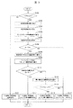
- Step S100 information on the amount of accelerator depression is acquired to determine the traveling state of the host vehicle. If it is determined that the accelerator pedal is depressed, the driver determines that the vehicle is running normally, and does not execute the automatic stop and restart function that automatically stops and restarts the engine. Proceed to step S101. On the other hand, if it is determined in step S100 that the accelerator pedal is not depressed, an automatic stop and restart function for automatically stopping and restarting the engine and a clutch disengagement and engagement function are executed. Execute the process.
- Step S101 If it is determined in step S100 that the accelerator pedal 23 is depressed, in this step S101, after performing normal running in which the clutch is engaged and combustion of the engine is continued, the routine returns to the return and prepares for the next activation timing. Is.
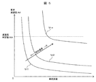
- Step S102 in order for the host vehicle to quickly decelerate including collision avoidance based on the amount of depression of the brake pedal of the host vehicle, the current relative speed between the host vehicle 36 and the preceding vehicle 35, the relative distance, and the like, The current required deceleration Ad required for the host vehicle 36 is calculated. As shown in FIG. 5, the required deceleration Ad is obtained by using a deceleration map determined from the inter-vehicle distance between the host vehicle 36 and the preceding vehicle 35 and the relative speed Vr.
- the required deceleration is determined by the relative speed Vr depending on the inter-vehicle distance and the relative speeds Vr1 to Vrn. The greater the inter-vehicle distance, the smaller the required deceleration, and the greater the relative speed (the speed of the host vehicle) is greater. Increases deceleration.
- This deceleration map is exemplary, and a deceleration map using other parameters may be used. Further, the brake depression amount may be referred to.
- the required deceleration Ad is set to a predetermined small required deceleration Ad or “0”. When this process is completed, the process proceeds to step S103.
- Step S103 an inertia deceleration A1 of the host vehicle when the host vehicle is coasting in a state where the accelerator pedal 23 and the brake pedal 25 are not depressed and the clutch is disengaged is calculated.
- the running resistance is obtained from one or more parameters such as the vehicle weight, Cd value, and gradient of the host vehicle, and is estimated based on the running resistance and the vehicle speed information of the host vehicle.
- the vehicle speed of the host vehicle and the deceleration during inertial running may be mapped by conforming work and estimated by referring to the vehicle speed. Further, it may be estimated from the deceleration at the time of the previous inertial running. Further, when correction information such as the number of passengers and the air pressure of the wheels can be acquired, the deceleration deceleration A1 may be corrected using these correction information. When this process is completed, the process proceeds to step S104.
- Step S104 the engine braking deceleration A2 is estimated and calculated when the host vehicle runs the engine brake while the accelerator pedal 23 and the brake pedal 25 are not depressed and the clutch is engaged.
- the estimation calculation method is to estimate the engine braking deceleration A2 by adding a predetermined value to the inertia deceleration A1 estimated in step S103.
- the resistance acting on the axle is estimated and calculated, or it is estimated from a map using the vehicle speed and the SOC of the battery as parameters, and from these, The engine braking deceleration A2 may be estimated. As is well known, the engine braking deceleration A2 is larger than the inertia braking deceleration A1. When this process is completed, the process proceeds to step S105.
- Step S105 a deceleration determination value Ath, which is estimated that the driver does not feel uncomfortable with the deceleration of inertial traveling, is calculated.
- the deceleration determination value Ath is a threshold value for determining whether the current deceleration state of the host vehicle may shift to inertial traveling or engine braking traveling. As shown in FIG. 5, the deceleration determination value Ath is rapidly decelerated when the required deceleration Ad is larger than the deceleration determination value Ath, and is slow when the required deceleration Ad is smaller than the deceleration determination value Ath. It is a standard to do.
- the inertia deceleration A1 obtained in step S103 is replaced with a deceleration determination value Ath, and a threshold value for comparison is set in the next step S105.
- the deceleration determination value Ath will be described as inertial deceleration A1.
- the inertia deceleration A1 of the travel path on which the host vehicle is currently traveling is “0”, that is, the host vehicle 36 is neither accelerated nor decelerated while coasting.
- a gradient change region gradient change from the start point of the gradient change is completed) that reduces the gradient in the downward direction relative to the gradient of the own vehicle, that is, decreases the deceleration of the own vehicle and turns the own vehicle to acceleration. If there is a point), since the deceleration operation of the host vehicle is predicted after passing through the gradient change region, the required deceleration Ath may be set to “0”.
- step S106 the vehicle is immediately selected for engine braking. For this reason, compared with the case where coasting is performed while driving the engine until entering a downward slope, it is possible to save the amount of fuel consumed by not driving the engine (deceleration fuel cut).
- step S106 the process proceeds to step S106.
- step S107 it is possible to provide the driver with a sense of incongruity in the deceleration state caused by executing a small deceleration during inertial traveling, and to provide a decelerating travel without any discomfort due to engine braking. Then, after executing “engine brake traveling control” in step S107, the process returns to the return and prepares for the next activation timing.
- Fig. 6 shows how to calculate the pedal-off duration.
- the vehicle speed during coasting changes as shown by the vehicle speed Sd with the passage of time as shown by the broken line in FIG.
- the relative speed and the change in the inter-vehicle distance are predicted from the information such as the vehicle speed, acceleration, and inter-vehicle distance of the preceding vehicle 35 obtained using the external recognition sensor 21. Using this information, the time until the host vehicle 36 steps on the brake pedal 25 next time is calculated. In inertial running, the clutch is disengaged, so the vehicle speed of the host vehicle 36 is faster than engine braking, and the distance between the vehicle and the preceding vehicle 35 tends to be shortened. Is expensive.
- the condition for depressing the brake pedal 25 on the host vehicle 36 is, for example, as shown by a broken line in FIG. 6C, where TTC (Time-To-Collision) is equal to or less than a predetermined value (brake pedal reference TTC). Therefore, it is estimated that the brake pedal 25 is depressed in a situation where it is predicted that it is necessary to decelerate rapidly to avoid a collision.
- TTC time-To-Collision
- the pedal-off duration time T1 and the pedal-off duration time T2 obtained in the next step S109 correlate with the fuel cut time for stopping the engine drive. The longer the pedal-off duration time, the greater the effect of improving the fuel consumption.
- Step S109 Similar to step S108, in step S109, when the host vehicle 36 performs engine brake traveling, a pedal-off duration T2 during which engine brake traveling can be continued is calculated.
- Fig. 6 shows how to calculate the pedal-off duration.
- the relative speed and the change in the inter-vehicle distance are predicted from the information such as the vehicle speed, acceleration, and inter-vehicle distance of the preceding vehicle 35 obtained using the external recognition sensor 21. Using this information, the time until the host vehicle 36 steps on the accelerator pedal 23 next time is calculated. Since the clutch is engaged in the engine brake travel, the vehicle speed of the host vehicle 36 is slower than the inertia travel, and the inter-vehicle distance from the preceding vehicle 35 tends to increase. Therefore, the host vehicle 36 may step on the accelerator pedal 23. Is expensive.
- the condition for depressing the accelerator pedal 23 in the host vehicle 36 is, for example, as shown by the solid line in FIG. 6B, the relative speed becomes “0” or more (accelerator step reference relative speed). It is estimated that the accelerator pedal 23 is depressed when the relationship of vehicle speed ⁇ vehicle speed of the host vehicle is satisfied.
- step S108 and step S109 when the preceding vehicle 35 is not detected, the time until the vehicle speed of the host vehicle is equal to or lower than the predetermined vehicle speed when the inertial running is assumed is referred to as a pedal-off continuation time T1.
- the time until the vehicle speed of the host vehicle becomes equal to or lower than the predetermined vehicle speed when it is assumed that the engine brake travel is performed may be determined as the pedal-off continuation time T2. Note that the predetermined vehicle speeds may be different from each other.
- the probability that the acceleration will change is considered to be high in the present embodiment, for example, when the host vehicle and the preceding vehicle enter a downhill.
- the fuel cut is performed by turning off the accelerator, the speed of the host vehicle increases when entering a downhill, and the fuel cut condition is changed by depressing the brake pedal, and the engine is restarted. For this reason, in order to suppress the frequency
- the change area of the gradient can be detected by, for example, a stereo camera that is the external recognition sensor 21. That is, in FIGS. 4A and 4B, the change in the position of the characteristic part of the preceding vehicle 35, for example, the rear bumper can be used. Since the lower end position of the rear bumper changes in the vertical direction when the preceding vehicle 35 passes through the gradient change start point, it can be acquired using this change. According to this method, since the gradient change area information can be acquired by the external recognition sensor 21, the gradient information can be detected without using a navigation device including the gradient information.
- the present invention is not limited to this method, and the presence / absence of a change in the gradient of the traveling road (which can be inferred from the disappearance of the white line) may be estimated from the shape of the white line of the road.
- a change in the gradient of the traveling road may be estimated from information such as the gradient of the traveling road or the altitude.
- the presence / absence and position of the traveling road gradient may be acquired from other vehicles including the preceding vehicle, communication infrastructure on the road, and the like by wireless communication.
- the determination of the probability that the acceleration changes in step S110 may be continued even after the host vehicle 36 has actually passed through the downward slope change region.
- the host vehicle 36 has entered the downward slope, it is possible to determine whether to stop the engine after acquiring information about the slope of the slope or a change in the deceleration of the host vehicle 36 due to the slope.
- step S110 If it is determined in step S110 that an event occurs in which the acceleration of the host vehicle 36 or the preceding vehicle 35 changes within the pedal-off duration T1, the process proceeds to step S111. On the other hand, if it is determined in step S110 that an event in which the acceleration of the host vehicle 36 or the preceding vehicle 35 changes does not occur within the pedal-off continuation time T1, the process proceeds to step S112.
- Step S111 since it is highly probable that the acceleration will change, a clutch disengagement process is performed, and "engine drive and inertial running control" for continuing the engine drive is executed. At this time, it is desirable that the engine be in an idle state from the viewpoint of fuel efficiency, but it can be changed according to a request transmitted from the ECU or the like.
- Step S112 If it is determined in step S110 that an event in which the acceleration changes does not occur within the pedal-off duration T1, in step S112, the pedal-off duration T1 and T2 calculated in steps S108 and S109 are used to perform inertial driving. The minimum inertial running duration Tth that can be expected to improve fuel efficiency is calculated.
- the inertia running duration Tth is, for example, the inertia running duration Tth when it is assumed that the fuel efficiency effect of inertia running can be obtained when the pedal off duration T1 in inertia running is longer than the pedal off duration T2 in engine braking.
- the pedal-off continuation time T2 for braking is set.
- the inertia traveling duration Tth is replaced with a predetermined value set in advance.
- the predetermined value may be a value obtained by dividing the amount of fuel injected at the start of the engine by the amount of fuel consumed per second in the idle state. With this setting, it is possible to determine whether or not fuel that is greater than the amount of fuel consumed when the engine is started can be saved. When this process is completed, the process proceeds to step S113.
- the process proceeds to step S114.
- step S108 This determination is to determine which can improve the fuel efficiency between coasting and engine braking.
- "Engine stop and inertial running control” is executed. With this control, when the engine stop time during inertia traveling, that is, the fuel cut time is longer than the fuel cut time during engine brake travel, the “engine stop and inertia travel control” can be performed, so that an effect of improving fuel efficiency can be obtained. Be able to.
- step S112 and step S113 are executed.
- step S112 and step S113 may be omitted depending on circumstances.
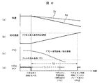
- FIG. 7 shows the speed of the host vehicle, the change in the height of the rear bumper of the preceding vehicle, the engagement state of the clutch, and the engine speed when the above-described control is executed.
- state 1 is a state where only the preceding vehicle 35 is entering a downward slope as shown in FIG. 4A
- state 2 is a state where the host vehicle 36 is also entering a downward slope as shown in FIG. 4B. Yes.
- the stereo camera detects the position of the rear bumper of the preceding vehicle 35. Therefore, as shown in the state 1, as the preceding vehicle 35 progresses downhill, The bumper position moves downward. On the other hand, when the host vehicle 36 also travels downhill, the position of the rear bumper does not change as shown in state 2. Therefore, it is determined that there is a high probability that the acceleration changes in the initial period of state 1.
- the clutch is disengaged from the engaged state as shown in FIG.
- the fuel injection amount is controlled to be the idling speed.
- the driving of the engine is conventionally stopped, but in the present embodiment, the engine is driven in an idling state. Therefore, when the state is shifted to the state 2, conventionally restarting is necessary. However, in this embodiment, it is not necessary to restart the engine, so that the number of operations of auxiliary components such as a starter can be reduced.
- the control flow shown in FIG. 3 is executed. For example, it is determined whether the engine brake is necessary, and the engine brake is necessary. If it is determined, the clutch is re-engaged and the rotation from the wheel is transmitted to increase the engine speed. Thereafter, as the deceleration progresses, the engine speed gradually decreases.
- the present embodiment is different from the first embodiment in that the present embodiment targets a traveling road in which a curvature changing region such as a curve exists.
- a traveling path in which the curvature changes in front of the host vehicle 36 and the preceding vehicle 35 in a state where the host vehicle 36 is traveling following the preceding vehicle 35 (so-called “so-called”).
- a curved traveling path) There is a curved traveling path), and the vehicle travels along this traveling path.
- a curvature change start point and a curvature change completion point are set for convenience in the travel path, and the curvature change start point and the curvature change completion point are recognized by the external recognition means 21.
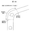
- FIG 8A shows a state in which the host vehicle 36 has not yet entered the curvature change area of the travel path and the preceding vehicle 35 has entered the travel path of the curvature change area. And the own vehicle 35 is decelerating as it enters the curvature change region, and the inter-vehicle distance between the own vehicle 36 and the preceding vehicle 35 is increased.
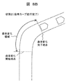
- FIG. 8B shows a state in which the host vehicle 36 enters the travel path in the curvature change region after a lapse of time, and then the host vehicle 36 and the preceding vehicle 35 travel out of the curvature change region. Then, the host vehicle 36 is accelerated by exiting the curvature change region, and the inter-vehicle distance between the host vehicle 36 and the preceding vehicle 35 is shortened.
- steps S100 to S109 and steps S111 to S114 are the same control steps, and thus description thereof is omitted.
- step S110 it is determined whether or not the host vehicle 36 enters the curvature change point of the travel path within the pedal-off duration T1 calculated in step S108.
- the acceleration of the host vehicle may change due to the driver of the host vehicle 36 performing a deceleration action.
- the curvature change region can be detected by, for example, a stereo camera that is the external recognition sensor 21. That is, in FIGS. 8A and 8B, when the characteristic portion of the preceding vehicle 35, for example, the position of the rear bumper passes the curvature change start point, the lower end position of the rear bumper changes in the left-right direction. According to this method, since the curvature change area information can be acquired by the external recognition sensor 21, the curvature information can be detected without using a navigation device including the curvature information.
- the present invention is not limited to such a method, and the presence or absence of a change in the curvature of the road (can be estimated by the white line being bent) may be estimated from the shape of the white line on the road, or the vehicle may be driven from the map information of the navigation device.
- the curvature change of the traveling road may be estimated from the curvature information of the road.
- the presence / absence of the curvature change of the traveling road and the position may be acquired from other vehicles including the preceding vehicle, communication infrastructure on the road, and the like by wireless communication.
- step S110 and subsequent steps processing similar to that in the first embodiment is performed.
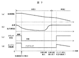
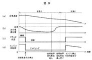
- FIG. 9 shows the speed of the host vehicle, the change in the lateral position of the rear bumper of the preceding vehicle, the clutch engagement state, and the engine speed when the above-described control is executed.
- state 1 is a state where the preceding vehicle 35 has entered the curvature change region as shown in FIG. 8A
- state 2 is a point where both the preceding vehicle 35 and the host vehicle 36 have completed the change in curvature as shown in FIG. 8B. Shows the state of exiting.
- the clutch is disengaged from the engaged state as shown in FIG.
- the fuel injection amount is controlled to be the idling speed.
- the driving of the engine is conventionally stopped, but in the present embodiment, the engine is driven in an idling state. Therefore, when the state is shifted to the state 2, conventionally restarting is necessary. However, in this embodiment, it is not necessary to restart the engine, so that the number of operations of auxiliary components such as a starter can be reduced.
- the control flow of the present embodiment is executed. For example, it is determined whether engine braking is necessary, and engine braking is necessary. When judged, the clutch is re-engaged to transmit the rotation from the wheel, and the engine speed increases. Thereafter, as the deceleration progresses, the engine speed gradually decreases.
- the present embodiment by determining the probability that the driver of the own vehicle will perform a deceleration operation according to the change in the curvature of the traveling path, by continuing the engine drive during inertial traveling until the change in the curvature of the traveling path is completed, The number of times the engine is restarted can be suppressed.
- the present embodiment can be further improved by adding the following technical functions.
- the following technical functions are provided in the vehicle integrated control unit. Specifically, it is a function incorporated in the software of the microcomputer.
- the probability that the acceleration of the host vehicle or the preceding vehicle will change will be lower during the time that the engine is driven after the clutch is disengaged, that is, the acceleration of the host vehicle. Until a change in acceleration of the host vehicle is completed.
- the state in which the acceleration of the host vehicle or the preceding vehicle changes is a state in which the resistance of the wheel and the road surface of the host vehicle such as a puddle, snow accumulation, road surface freezing, etc. existing in front of the host vehicle is reduced. It can be determined that the probability that the acceleration changes is high.
- the state in which the acceleration of the host vehicle or the preceding vehicle changes is a state in which the resistance of the wheels of the host vehicle and the road surface such as a gravel road existing in front of the host vehicle is increased, and the acceleration changes by detecting this. It can be determined that there is a high probability of being.
- an abnormality detection means for determining an abnormality of the external recognition means is provided, and it is determined that an abnormality has occurred in the external recognition means, and the clutch is disengaged while the host vehicle is traveling at a predetermined vehicle speed or higher. If it is, the engine can be driven to increase the safety by re-engaging the clutch.
- the deceleration information of the own vehicle at the time of the previous or current coasting is calculated based on at least one of the vehicle speed of the own vehicle, the deceleration information of the own vehicle at the time of the previous or current coasting, the vehicle weight of the own vehicle, or the slope information of the road on which the own vehicle travels. It is possible to calculate the deceleration during inertial running. In other words, the deceleration compared with the required deceleration for determining whether the required deceleration that requires engine braking or inertial driving is determined based on the vehicle speed and running resistance of the host vehicle. It is possible to estimate and calculate the deceleration during inertia.
- the present invention when there is a high probability of restarting the engine with the engine stopped and inertial running control, only the clutch is disengaged and the engine continues to drive at a predetermined speed. And the configuration. According to this, for example, when it is determined that there is a high probability that the acceleration of the host vehicle or the preceding vehicle changes and the engine is restarted, the clutch is disengaged and coasting is performed, and the engine is in a driving state. Thus, it is not necessary to restart the engine, and the number of restarts can be suppressed.
- the fuel consumption can be improved by stopping the engine and inertial running control, and the number of restarts in the lifetime of the automobile is reduced. Therefore, adverse effects on auxiliary components such as starters and batteries can be reduced. .
- this invention is not limited to the above-mentioned Example, Various modifications are included.
- the above-described embodiments have been described in detail for easy understanding of the present invention, and are not necessarily limited to those having all the configurations described.
- a part of the configuration of one embodiment can be replaced with the configuration of another embodiment, and the configuration of another embodiment can be added to the configuration of one embodiment.
- SYMBOLS 10 ... Engine, 11 ... Automatic transmission, 12 ... Propeller shaft, 13 ... Differential gear, 14 ... Drive shaft, 15R, 15F ... Wheel, 17 ... Friction brake, 18 ... Engine control unit, 19 ... Transmission control unit, 20 DESCRIPTION OF SYMBOLS ... Vehicle integrated control unit, 21 ... Outside world recognition means, 22 ... Wheel speed sensor, 23 ... Accelerator pedal, 24 ... Accelerator pedal sensor, 25 ... Brake pedal, 26 ... Brake pedal sensor, 27 ... Direction indicator sensor, 28 ... Gyro Sensor: 29 ... Fuel injection valve, 30 ... Ignition unit, 31 ... Electric throttle valve, 32 ... System determination unit, 33 ... Clutch state determination unit, 34 ... Engine state determination unit, 35 ... Preceding vehicle, 36 ... Both vehicles .
Abstract
エンジン停止及び惰性走行制御を行ないながら、停止及び再始動回数を低減することができる新規な自動車の制御装置を提供することになる。 エンジン停止及び惰性走行制御を行なう状態でエンジンを再始動させる蓋然性が高い状態の時には、クラッチだけを切断すると共に、エンジンはアイドル回転で運転を続ける構成とした。例えば、自車両や先行車両の加速度が変化して再始動する蓋然性が高いと判断されると、クラッチを切断して惰行走行を行うと共に、エンジンはアイドリング状態としているので再始動を行う必要なく、再始動回数を抑制することができるようになる。
Description
本発明は自動車の制御装置に係り、特にエンジンを自動的に停止させて再始動する自動停止及び再始動機能を備える自動車の制御装置に関するものである。
近年、燃費向上、排気エミッション低減等を目的として、エンジンの自動停止及び再始動制御システムを搭載した自動車が増加している。従来の一般的な自動停止及び再始動制御システムは、運転者が車両を停車させたときに燃料噴射と火花点火を停止してエンジンを自動的に停止させ、その後、運転者が車両を発進させようとする操作(ブレーキ解除操作やアクセル踏込み操作等)を行ったときに自動的にスタータ又はスタータ兼用のモータに通電してエンジンをクランキングして再始動させるようにしている。
更に、最近では走行中に或る所定の条件が成立すると、エンジンを一時的に停止すると共に、自動変速機とエンジンの間に介装されているクラッチを切断して自動車を惰性で走行させ、その後に所定の条件が成立するとエンジンを再始動し、クラッチを再締結する制御(以下、エンジン停止及び惰性走行制御と表記する)が実施されている。これは、アクセルペダルを踏まない状態で長い時間に亘って、エンジンを停止して車速を維持できるので、燃費の向上が期待できるものである。
このようなエンジン停止及び惰性走行制御は、例えば、特開2007-291919号公報(特許文献1)に記載されている。特許文献1には、自車両と先行車両の車間距離が最大車間距離よりも大きくなったときに、自車両が下り勾配を走行中であれば、駆動力の発生を開始せずに自車両を惰性走行させることが記載されている。
ところで、上述したようなエンジン停止及び惰性走行制御は燃費改善の上では効果があるが、自動車の生涯における再始動回数が増大するため、スタータやバッテリなどの補機コンポーネントへの悪影響が大きくなる。よって、燃費が確実に改善されるという条件が成立しなければ、できるだけエンジンの停止及び再始動は避け、停止及び再始動回数を低減するほうが望ましいものである。
そして、特許文献1においては、自車両が走行している勾配の情報を用いてエンジンの駆動を停止しているので、惰性走行中に勾配が変わる、先行車両が加速したというような場合にエンジンの再始動が必要になる可能性が高くなり、エンジンの再始動回数が増大するという課題が新たに発生する。したがって、エンジン停止及び惰性走行制御を行ないながら燃費の改善を行い、しかもできるだけエンジンの停止及び再始動回数を低減する制御技術の開発が強く要請されている。
本発明の目的は、エンジン停止及び惰性走行制御を行ないながら、停止及び再始動回数を低減することができる新規な自動車の制御装置を提供することにある。
本発明の特徴は、エンジン停止及び惰性走行制御を行なう状態下でエンジンを再始動させる蓋然性が高い状態の時には、クラッチだけを切断すると共に、エンジンは所定の回転数で駆動を継続する、ところにある。尚、所定の回転数は、好ましくはアイドル回転数が適しており、これによって燃料消費量をより少なくすることができる。
本発明によれば、例えば、自車両や先行車両の加速度が変化してエンジンを再始動する蓋然性が高いと判断されると、クラッチを切断して惰行走行を行うと共に、エンジンは駆動状態としているので、エンジンの再始動を行う必要がなく再始動回数を抑制することができるようになる。
次に、本発明の実施例について図面を用いて詳細に説明するが、本発明は以下の実施例に限定されることなく、本発明の技術的な概念の中で種々の変形例や応用例をもその範囲に含むものである。
図1は自動車の駆動系の概略構成を示すものであり、走行用動力源としての筒内噴射式のエンジン10と、エンジン10の回転力を変速機構によって調整する自動変速機11と、自動変速機11の回転を車輪に伝えるプロペラシャフト12と、プロペラシャフト12と連結されたディファレンシャルギア13と、ディファレンシャルギア13と連結されたドライブシャフト14と、ドライブシャフト14によって駆動される後輪15Rと、操舵装置によって操舵される前輪15Fと、各車輪15F、15Rに設けられた摩擦ブレーキ17を備えている。
ここで、エンジン10と自動変速機11の間にはクラッチ機構(図示せず)が介装されており、クラッチを締結することでエンジン10の回転を自動変速機11に伝え、クラッチを切断することでエンジン10の回転を自動変速機11に伝えないようにしている。
エンジン10はエンジン制御ユニット18によって制御され、自動変速機11は変速機制御ユニット19によって制御されている。尚、上述したクラッチ機構も変速機制御ユニット19によって制御されている。エンジン制御ユニット18と変速機制御ユニット19は互いに通信回線を介して通信されている。
更に、エンジン制御ユニット18と変速機制御ユニット19は車両統合制御ユニット20に通信回線を介して通信されている。車両統合制御ユニット20には、外界認識手段21、車輪15F、15Rの回転速度を検出する車輪速センサ22、アクセルペダル23が踏み込まれたことを検出するアクセルペダルセンサ24、ブレーキペダル25が踏み込まれたことを検出するブレーキペダルセンサ26、方向指示器信号27、ジャイロセンサ28等からの情報が入力されている。
次に、車両統合制御ユニット20の詳細について図2を用いて説明する。図2において、車両統合制御ユニット20、エンジン制御ユニット18、変速機制御ユニット19等のマイクロコンピュータを内蔵した夫々の制御ユニットは、通信回線で制御情報が転送される構成とされている。また、夫々の制御ユニットと後述するセンサ類を含むアクチュエータ、機器類は、車内LAN(CAN)を介して制御情報の授受を行えるようになっている。
外界認識手段21は、マイクロコンピュータを内蔵した制御ユニット部を有しており、制御ユニット部は、撮影された映像に基づいて、自車両の前方の先行車両と自車両との相対速度、自車両の前方の先行車両、障害物、対向車等と自車両との距離(車間距離等)、先行車両の走行路の路面からの上下方向の高さや横方向の位置の差などの各種情報を算出し、その算出結果を車両統合制御ユニット20に送信する。
外界認識手段21としては、レーザーレーダーやミリ波レーダー、モノカメラ、ステレオカメラ等のうちの一つないし複数を組み合わせて使用しても良い。また、路車間通信、あるいは車々間通信を用いて取得しても良いものである。本実施例ではステレオカメラを使用している。
また、車両統合制御ユニット20には、各車輪15F、15Rの回転速度を検出する4つの車輪速センサ22、アクセルペダル23が踏み込まれたことを検出するアクセルペダルセンサ24、ブレーキペダル25が踏み込まれたことを検出するブレーキペダルセンサ26、方向指示器信号27、ジャイロセンサ28等からの情報も入力されている。
エンジン制御ユニット18には、車両統合制御ユニット20や変速機制御ユニット14等からの制御情報の他に、エンジン10に配備されたセンサ類からエンジン10の運転状態(例えば、エンジン回転数、吸入空気量、スロットル開度、筒内圧力等)を表わす、あるいはそれらを求める際の基礎となる様々な情報が入力されている。また、エンジン制御ユニット18は、これらの情報に基づいて燃料噴射弁29、点火コイルや点火プラグ等からなる点火ユニット30、電制スロットル弁31等に所定の駆動信号を送信し、燃料噴射(時期、量)制御、点火(通電角、点火時期)制御、スロットル開度制御等を実行するものである。
ここで、本実施例においてはエンジン停止及び惰行走行制御を実行するため、アクセルペダル23、ブレーキペダル25が踏み込まれていないペダルオフ時の制御を前提とするものである。
車両統合制御ユニット20は、本実施例に関係するものとしてシステム判定部32、クラッチ状態決定部33、及びエンジン状態決定部34とを有している。これらのシステム判定部32、クラッチ状態決定部33、及びエンジン状態決定部34は自動停止及び再始動手段として機能する。
システム判定部32は、4つの車輪速センサ22やアクセルペダルセンサ24からの情報に基づいて、自車両の速度とアクセルペダルの踏み込み量を算出する。更に、システム判定部32は、アクセルペダルセンサ24、方向指示器27、ブレーキペダルセンサ26、外界認識センサ21から得た先行車両との相対関係(例えば、相対速度、相対距離等)の情報に基づいて、自車両の衝突回避等を速やかに行うために必要な減速度(以下、要求減速度という)を算出する。そして、この要求減速度が所定値(例えば、エンジンブレーキにより発生すると推定される減速度)以上であれば、エンジンブレーキによる減速アシストが必要であると判定する。
一方、要求減速度が所定値以下であればエンジンブレーキが不要と判断され、かつこの判断のもとで自車両の車速が所定値以上の場合、(1)クラッチを締結した状態のエンジンブレーキ走行と、(2)クラッチを切断した状態の惰性走行を行った場合の夫々で、アクセルペダル23が踏み込まれなくなった時点(ペダルオフ時点)からアクセルペダル23、またはブレーキペダル25が踏まれるまでの時間(以下、共にペダルオフ継続時間とする)を計算する。この計算については後述のフローチャートで説明する。
また、自車両のアクセルペダル23、及びブレーキペダル25が踏まれていない状態で、自車両、または先行車両の加速度が変化する蓋然性(=エンジンを再始動させる蓋然性)を判定する。尚、ここで蓋然性とは確からしさの度合いを意味している。
そして、これらの結果をクラッチ状態決定部33とエンジン状態決定部34へ送信する。例えば、自車両のアクセルペダル23、及びブレーキペダル25が踏まれていない状態で自車両が加速する場合は、下り勾配の走行路を走行する場合が想定される。また、先行車両が加速する場合は先行車両の運転者によって加速された場合が想定される。
尚、これ以外の要因でも自車両、または先行車両の加速度が変化する場合がある。要は、自車両、または先行車両の加速度が変化する事象を検出して加速度が変化する蓋然性を判定すれば良いものである。ここで、加速度が変化するとは減速される場合も含むものである。
クラッチ状態決定部33は、アクセルペダル23が踏まれておらず、かつエンジンブレーキ走行が不要と判定された状態で、惰性走行を行った場合のペダルオフ継続時間がエンジンブレーキ走行を行った場合のペダルオフ継続時間よりも長いと判断されたときに、クラッチ切断(=解放)許可と判断する機能を備えている。
また、クラッチ状態決定部33は、(1)アクセルペダル23が踏まれていると判定される、或いは(2)エンジンブレーキによる減速アシストが必要と判定される、或いは(3)惰性走行を行った場合のペダルオフ継続時間がエンジンブレーキ走行を行った場合のペダルオフ継続時間より短いと判定されるときに、クラッチ締結条件が成立したと判断する機能を備えている。
エンジン状態決定部34は、アクセルペダル23が踏まれておらず、かつクラッチ状態決定部33でクラッチ切断許可の判定がなされていない場合は、燃料停止条件が成立したと判断する。これにより、先行車両への衝突回避のために比較的強い減速が必要な場合や、エンジンブレーキ走行でのペダルオフ継続時間が、惰性走行でのペダルオフ継続時間に比べて長くなる場合に、エンジンブレーキ走行を選択することができる。ここで、ペダルオフ継続時間は燃料停止時間であり、エンジンブレーキ走行でのペダルオフ継続時間が長いということは、惰性走行による燃費の改善効果に比べてエンジンブレーキ走行の方が燃費の改善効果が大きいことを意味している。
また、エンジン状態決定部34は、システム判定部51でアクセルペダル23、ブレーキペダル25が踏まれておらず、かつクラッチ状態決定部33でクラッチ切断許可と判定されているときは、自車両のペダルオフ中に自車両または先行車両の加速度が変化する可能性の蓋然性を判定する。加速度が変化する蓋然性が高いと判定されている場合は、クラッチを切断した状態でエンジンの燃焼を継続する。
加速度が変化する蓋然性は、本実施例では例えば、自車両及び先行車両が下り坂に進入する状況の場合が、加速度が変化する蓋然性が高いと見做される。つまり、従来の方法ではアクセルオフによって減速燃料カットを行っている状態で、下り坂に進入すると自車両の速度が速くなり、ブレーキペダルを踏むことによって減速燃料カットの条件が変化してエンジンが再始動される。このため、本実施例ではエンジンの再始動回数を抑制させるために、再始動が必要となる加速度が変化する蓋然性を判断している。
また、曲線状道路の曲率変化領域に進入した場合にも加速度が変化する蓋然性が高いと見做されるが、これについては後述の実施例2で説明する。尚、本実施例1及び後述の実施例2にある加速度が変化する蓋然性の判断については、あくまでも例示的なものであり、これ以外のパラメータを使用して加速度が変化する蓋然性を判定して良いことはいうまでもない。
一方、加速度が変化する蓋然性が低いと判定されている場合は、クラッチを切断した状態で、エンジンへの燃焼供給を停止してエンジンの回転を完全に停止させる。
これらの処理を行うことで、惰性走行時において加速度が変化する蓋然性を判断することで、加速度が変化する蓋然性が低い場合は、エンジンを停止させるので燃費の改善効果を向上することができる。また、加速度が変化する蓋然性が高い場合は、エンジンを停止させないので、エンジンの停止及び再始動回数を低減できて補機コンポーネントの寿命を長くすることができるようになる。
変速機制御ユニット19は、クラッチ状態決定部33からクラッチ切断指令が送信されると、直ちにクラッチを切断して自車両の減速度を小さくし、惰性走行状態を実現する。一方、クラッチ状態決定部33からクラッチ締結指令が送信されると、クラッチの締結を維持する、或いはクラッチが切断されていれば、エンジンの回転と車輪の回転が同期するのを待って、直ちにクラッチを締結する。これにより、エンジンブレーキ走行を実行するか、または車輪にエンジンの駆動力が伝わる駆動状態とすることができる。
エンジン制御ユニット18は、エンジン状態決定部34からエンジンの停止指令が送信されると、燃料噴射弁29への燃料噴射駆動パルス信号の供給を停止し、更に点火ユニット30への点火信号の供給を停止してエンジン10を停止するように動作する。また、エンジン制御ユニット18は、エンジン状態決定部34からエンジンの再始動指令が送信されると、燃料噴射弁29への燃料噴射駆動パルス信号の供給を再開し、更に点火ユニット30への点火信号の供給を再開して、エンジン10の再始動を行うように動作する。
上述した車両統合制御ユニット20のシステム判定部32、クラッチ状態決定部33、及びエンジン状態決定部34は、実際にはマイクロコンピュータによって実行されている制御プログラムの制御機能であるので、次に具体的な制御を図3に示す制御フローを参照しながら説明する。
尚、図3に示す制御フローは所定時間毎の起動タイミングで起動されるものであり、スタートからリターンまでの各制御ステップを実行した後に、次の起動タイミングの到来で再びスタートからリターンまでの各制御ステップを繰り返して実行するものである。この起動タイミングは、例えばフリーランカウンタのコンペアマッチ割り込みによって所定時時間毎に起動されている。
本実施例では図4A、図4Bに示すように、先行車両35に自車両36が追従して走行している状態で、自車両36及び先行車両35の前方に下り勾配の走行路が存在し、この走行路を走行している状態を対象にしている。走行路には説明の都合上、勾配変化開始地点、勾配変化完了地点、及び勾配情報取得完了地点が便宜上設定されており、外界認識手段21によって勾配変化開始地点、勾配変化完了地点、及び勾配情報取得完了地点が認識されるものである。
図4Aにおいて、自車両36はまだ下り勾配の走行路には進入していなく、先行車両35が下り勾配の走行路に進入している状態を示している。そして、先行車両35は下り勾配に進入しているので加速されており、自車両36と先行車両35の間の車間距離が長くなっている状態を示している。
図4Bにおいて、時間が経過して自車両36が下り勾配の走行路に進入し、更に先行車両35が下り勾配の走行路を走行している状態を示している。そして、自車両36は下り勾配に進入しているので加速されており、自車両36と先行車両35の間の車間距離が短くなっている状態を示している。
このような状態における車両統合制御ユニット20の動作を図3に示す制御フローを参照しながら説明する。
≪ステップS100≫
ステップS100では、自車両の走行状態を判断するためアクセル踏込量の情報を取得する。アクセルペダルが踏み込まれていると判断されると、運転者が通常の走行を行っていると判断して、エンジンを自動的に停止させて再始動する自動停止及び再始動機能を実行しないで、ステップS101に進む。一方、ステップS100でアクセルペダルが踏み込まれていないと判断されると、エンジンを自動的に停止させて再始動する自動停止及び再始動機能、及びクラッチ切断及び締結機能を実行するため、ステップS102以降の処理を実行する。
ステップS100では、自車両の走行状態を判断するためアクセル踏込量の情報を取得する。アクセルペダルが踏み込まれていると判断されると、運転者が通常の走行を行っていると判断して、エンジンを自動的に停止させて再始動する自動停止及び再始動機能を実行しないで、ステップS101に進む。一方、ステップS100でアクセルペダルが踏み込まれていないと判断されると、エンジンを自動的に停止させて再始動する自動停止及び再始動機能、及びクラッチ切断及び締結機能を実行するため、ステップS102以降の処理を実行する。
≪ステップS101≫
ステップS100でアクセルペダル23が踏み込まれていると判断されると、このステップS101では、クラッチを締結してエンジンの燃焼を継続する通常走行を実行した後にリターンに抜けて、次の起動タイミングに備えるものである。
ステップS100でアクセルペダル23が踏み込まれていると判断されると、このステップS101では、クラッチを締結してエンジンの燃焼を継続する通常走行を実行した後にリターンに抜けて、次の起動タイミングに備えるものである。
≪ステップS102≫
ステップS102では、自車両のブレーキペダルの踏込量、及び現在の自車両36と先行車両35との相対速度、相対距離等から、自車両が衝突回避を含めた減速走行を速やかに行うために、自車両36に必要とされている現在の要求減速度Adを算出する。図5に示すように要求減速度Adは、自車両36と先行車両35との車間距離、及び相対速度Vrから決まる減速度マップを用いて求められている。
ステップS102では、自車両のブレーキペダルの踏込量、及び現在の自車両36と先行車両35との相対速度、相対距離等から、自車両が衝突回避を含めた減速走行を速やかに行うために、自車両36に必要とされている現在の要求減速度Adを算出する。図5に示すように要求減速度Adは、自車両36と先行車両35との車間距離、及び相対速度Vrから決まる減速度マップを用いて求められている。
車間距離及び相対速度Vr1~Vrnによって、夫々の相対速度Vrで要求減速度が決まるものであり、車間距離が大きいほど要求減速度は小さく、相対速度(自車両の速度が大きい)が大きいほど要求減速度が大きくなる。尚、この減速度マップは例示的なものであり他のパラメータを用いた減速度マップを使用しても良いものである。更には、ブレーキの踏み込み量を参照しても良い。また、先行車両35が検出されず、ブレーキペダル25の踏み込みがない場合は、要求減速度Adは所定の小さい要求減速度Ad、或いは「0」が設定される。この処理が完了するとステップS103に移行する。
≪ステップS103≫
ステップS103では、アクセルペダル23、ブレーキペダル25が踏み込まれていなくクラッチを切断している状態で、自車両が惰性走行を行った場合の自車両の惰性時減速度A1を推定演算する。推定演算の方法は、自車両の車両重量、Cd値、勾配等の1つ以上のパラメータによって走行抵抗を求め、この走行抵抗と自車両の車速情報を基に推定するものである。
ステップS103では、アクセルペダル23、ブレーキペダル25が踏み込まれていなくクラッチを切断している状態で、自車両が惰性走行を行った場合の自車両の惰性時減速度A1を推定演算する。推定演算の方法は、自車両の車両重量、Cd値、勾配等の1つ以上のパラメータによって走行抵抗を求め、この走行抵抗と自車両の車速情報を基に推定するものである。
また、自車両の車速と惰性走行時の減速度を適合作業によってマップ化し、これを車速によって参照して推定しても良いものである。また、前回の惰性走行時の減速度から推定しても良いものである。更に、乗員人数や車輪の空気圧等の補正情報を取得できる場合は、これらの補正情報を用いて惰性時減速度A1を補正しても良いものである。この処理が完了するとステップS104に移行する。
≪ステップS104≫
ステップS104では、アクセルペダル23、ブレーキペダル25が踏み込まれていなくクラッチが締結されている状態で、自車両がエンジンブレーキ走行を行った場合のエンジンブレーキ時減速度A2を推定演算する。推定演算の方法は、ステップS103で推定された惰性時減速度A1に所定値を加えてエンジンブレーキ時減速度A2を推定するものである。
ステップS104では、アクセルペダル23、ブレーキペダル25が踏み込まれていなくクラッチが締結されている状態で、自車両がエンジンブレーキ走行を行った場合のエンジンブレーキ時減速度A2を推定演算する。推定演算の方法は、ステップS103で推定された惰性時減速度A1に所定値を加えてエンジンブレーキ時減速度A2を推定するものである。
また、車速とバッテリのSOC(State Of Charge=残容量)の関係から、車軸に作用する抵抗力を推定演算する、或いは車速とバッテリのSOCをパラメータとするマップから推定し、これらから自車両のエンジンブレーキ時減速度A2を推定しても良いものである。エンジンブレーキ時減速度A2は、惰性時減速度A1より減速度が大きいのは周知の通りである。この処理が完了するとステップS105に移行する。
≪ステップS105≫
ステップS105では、運転者が惰性走行の減速度に違和感を持たないと推定される減速度判定値Athを算出する。この減速度判定値Athは、現在の自車両の減速状態が惰性走行に移行して良いか、或いはエンジンブレーキ走行に移行して良いかの判断を行うための閾値である。この減速度判定値Athは図5にあるように、要求減速度Adが減速度判定値Athより大きいと急速な減速を行い、要求減速度Adが減速度判定値Athより小さいと緩慢な減速を行う基準となるものである。本実施例ではステップS103で求めた惰性時減速度A1を減速度判定値Athとして置き換えて、次のステップS105で比較のための閾値としている。以下、減速度判定値Athを惰性時減速度A1として説明する。
ステップS105では、運転者が惰性走行の減速度に違和感を持たないと推定される減速度判定値Athを算出する。この減速度判定値Athは、現在の自車両の減速状態が惰性走行に移行して良いか、或いはエンジンブレーキ走行に移行して良いかの判断を行うための閾値である。この減速度判定値Athは図5にあるように、要求減速度Adが減速度判定値Athより大きいと急速な減速を行い、要求減速度Adが減速度判定値Athより小さいと緩慢な減速を行う基準となるものである。本実施例ではステップS103で求めた惰性時減速度A1を減速度判定値Athとして置き換えて、次のステップS105で比較のための閾値としている。以下、減速度判定値Athを惰性時減速度A1として説明する。
尚、図4Aに示しているように、自車両が現在走行している走行路の惰性時減速度A1が「0」、すなわち自車両36が惰性走行中に加速も減速もしない状態で、前方に、自車両の走行する勾配に対して相対的に下り方向の勾配、すなわち自車両の減速度を減少し、自車両を加速に転じさせるような勾配変化領域(勾配変化開始地点から勾配変化完了地点)が存在する場合は、勾配変化領域を通過した後に自車両の減速操作が予測されるため、要求減速度Athを「0」と設定しても良いものである。
尚、要求減速度Athを「0」と設定した場合、次のステップS106では、自車両は直ちにエンジンブレーキ走行が選択される。このため、下り勾配に入るまでエンジンを駆動しながら惰性走行を行う場合に比べて、エンジンを駆動しない(減速燃料カット)分だけ消費される燃料量を節約することができる。この処理が完了するとステップS106に移行する。
≪ステップS106≫
ステップS106では、ステップS103で求められた要求減速度Adと、ステップS106で求められた減速判定値Athの大きさを比較しており、現在の要求減速度Adが減速度判定値Ath(=A1)より大きいと判断されるとステップS107に進み、現在の要求減速度Adが減速度判定値Ath(=A1)より小さいと判断されるとステップS108に移行するものである。基本的には、ステップS107に進む場合は、減速度が大きいエンジンブレーキ走行であり、ステップS108に進む場合は、減速度が小さい惰性走行である。尚、惰性走行に移行する場合は、クラッチを切断した状態でエンジンを駆動しながら惰性走行する「エンジン駆動及び惰性走行制御」と、クラッチを切断した状態でエンジンを駆動しないで惰性走行する「エンジン停止及び惰性走行制御」のどちらか一方を実行する、
≪ステップS107≫
要求減速度Adが減速度判定値Ath(=A1)より大きいと判断されると、ステップS107では「エンジンブレーキ走行制御」を実行する。「エンジンブレーキ走行制御」では、クラッチを締結した状態でエンジンの駆動を停止(減速燃料カット)するものであり、要求減速度Adに対応して急速な減速を実行できる。これにより、惰性走行時の小さい減速を実行することによって生じる減速状態の違和感を運転者に与えることがなく、エンジンブレーキによって違和感のない減速走行を提供できるものとなる。そして、ステップS107で「エンジンブレーキ走行制御」を実行した後にリターンに抜けて、次の起動タイミング備えるものである。
≪ステップS108≫
ステップS107で要求減速度Adが減速度判定値Ath(=A1)より小さいと判断されると、ステップS109では自車両36が惰性走行を行った場合に、惰性走行を継続できるペダルオフ継続時間T1を推定演算する。
ステップS107で要求減速度Adが減速度判定値Ath(=A1)より小さいと判断されると、ステップS109では自車両36が惰性走行を行った場合に、惰性走行を継続できるペダルオフ継続時間T1を推定演算する。
ペダルオフ継続時間の算出方法を図6に示している。アクセルオフが発生した時刻をt=0とし、ステップS103において求められた惰性時減速度A1を用いて自車両36の車速の変化を予測する。惰性走行時の車速は、図6の(a)の破線で示すように時間経過と共に車速Sdに示すように変化する。
また、外界認識センサ21を用いて求められた先行車両35の車速、加速度、車間距離等の情報から、相対速度、及び車間距離の変化を予測する。これらの情報を用いて、自車両36が次にブレーキペダル25を踏むまでの時間を計算する。惰性走行ではクラッチが切断されているので自車両36の車速がエンジンブレーキ走行より速く、先行車両35との間の車間距離が短縮する傾向にあるので、自車両36ではブレーキペダル25を踏み込む可能性が高い。
そして、自車両36でブレーキペダル25を踏み込む条件は、例えば、図6の(c)の破線で示すように、TTC(Time-To-Collision:衝突時間)が所定値(ブレーキ踏み基準TTC)以下になり、衝突回避のために急速に減速する必要があると予測される状況で、ブレーキペダル25の踏み込みが行われると推定する。ここで、TTC=車間距離/相対速度の式によって求められている。
したがって、アクセルオフ(t=0)の後、惰性走行を行ったと仮定したときに、次にブレーキペダル25が踏み込まれると推定される時刻(t=t1)までの時間をペダルオフ継続時間T1として設定する。このペダルオフ継続時間T1及び次のステップS109で求めるペダルオフ継続時間T2は、エンジンの駆動を停止する燃料カット時間と相関しており、ペダルオフ継続時間が長いほど燃費の改善効果が大きいものである。この処理が完了するとステップS109に移行する。
尚、アクセルペダル23が踏み込まれる場合も想定され、この場合はアクセルペダル23を踏むまでの時間を計算する。
≪ステップS109≫
ステップS108と同様にステップS109では、自車両36がエンジンブレーキ走行を行った場合に、エンジンブレーキ走行を継続できるペダルオフ継続時間T2を算出する。
ステップS108と同様にステップS109では、自車両36がエンジンブレーキ走行を行った場合に、エンジンブレーキ走行を継続できるペダルオフ継続時間T2を算出する。
ペダルオフ継続時間の算出方法を図6に示している。アクセルオフが発生した時刻をt=0とし、ステップS104において求められたエンジンブレーキ時減速度A2を用いて自車両36の車速の変化を予測する。惰性走行時の車速は、図6の(a)の実線で示すように時間経過と共に車速Seに示すように変化する。
また、外界認識センサ21を用いて求められた先行車両35の車速、加速度、車間距離等の情報から、相対速度、及び車間距離の変化を予測する。これらの情報を用いて、自車両36が次にアクセルペダル23を踏むまでの時間を計算する。エンジンブレーキ走行ではクラッチが締結されているので自車両36の車速が惰性走行より遅く、先行車両35との間の車間距離が拡大する傾向にあるので、自車両36ではアクセルペダル23を踏み込む可能性が高い。
そして、自車両36でアクセルペダル23を踏み込む条件は、例えば、図6の(b)の実線で示すように、相対速度が「0」以上(アクセル踏み基準相対速度)になる、すなわち、先行車両の車速≧自車両の車速、の関係になったときにアクセルペダル23の踏み込みが行われると推定する。
したがって、アクセルオフ(t=0)の後、エンジンブレーキ走行を行ったと仮定したときに、次にアクセルペダル23が踏み込まれると推定される時刻(t=t2)までの時間をペダルオフ継続時間T2として設定する。この処理が完了するとステップS110に移行する。
尚、ステップS108、及びステップS109において、先行車両35が検出されなかった場合は、惰性走行を行ったと仮定したときに自車両の車速が所定の車速以下になるまでの時間をペダルオフ継続時間T1と設定し、同様にエンジンブレーキ走行を行ったと仮定したときに自車両の車速が上述の所定の車速以下になるまでの時間をペダルオフ継続時間T2と判断するようにしても良い。尚、所定の車速は夫々異なっていても良いものである。この処理が完了するとステップS110に移行する。
尚、ブレーキペダル25が踏み込まれる場合も想定され、この場合はブレーキペダル25を踏むまでの時間を計算する。
≪ステップS110≫
ステップS110では、ステップS108で算出したペダルオフ継続時間T1内に、自車両36、または先行車両35の加速度を変化させる事象が発生する蓋然性(=エンジンを再始動させる蓋然性)を判定する。
ステップS110では、ステップS108で算出したペダルオフ継続時間T1内に、自車両36、または先行車両35の加速度を変化させる事象が発生する蓋然性(=エンジンを再始動させる蓋然性)を判定する。
本実施例においては図4A、4Bに示すように、アクセルオフからペダルオフ継続時間T1内に自車両が下り勾配の走行路の変化領域に進入すると推定される場合、自車両36の加速度が変化すると判断して、加速度を変化させる事象が発生する蓋然性が高いと推定する。
加速度が変化する蓋然性は、本実施例では例えば、自車両及び先行車両が下り坂に進入する状況の場合において加速度が変化する蓋然性が高いと見做される。つまり、アクセルオフによって燃料カットを行っていると、下り坂に進入すると自車両の速度が速くなり、ブレーキペダルを踏むことによって燃料カットの条件が変化してエンジンが再始動される。このため、エンジンの再始動回数を抑制させるために、再始動が必要となる加速度が変化する蓋然性を判断している。
勾配の変化領域は、例えば外界認識センサ21であるステレオカメラによって検出することができる。つまり図4A、4Bにおいて、先行車両35の特徴部、例えばリアバンパーの位置の変化を利用することができる。先行車両35が勾配の変化開始地点を通過する際、リアバンパーの下端位置が上下方向に変化するので、この変化を利用して取得できる。この方法によれば、外界認識センサ21で勾配の変化領域情報を取得することができるため、勾配情報を含むナビゲーション装置を用いずに勾配情報を検出できる。
もちろん、このような方法に限定されずに、道路の白線形状から走行路の勾配変化の有無(白線が消失していることで推測可能)を推定しても良いし、ナビゲーション装置の地図情報から走行路の勾配、或いは標高等の情報から走行路の勾配の変化を推定しても良いものである。また、無線通信により、先行車両を含む他車両、道路上の通信インフラ等から走行路の勾配変化の有無、及び位置を取得しても良いものである。
更に、このステップS110における加速度が変化する蓋然性の判断は、自車両36が実際に下り勾配の変化領域を通過した後も、この判断を継続しても良いものである。これにより、自車両36が下り勾配に進入後、その勾配の傾きの情報、或いは勾配による自車両36の減速度の変化を取得した後に、エンジンの停止を行うかの判定を行うことができる。
ステップS110で、ペダルオフ継続時間T1内に自車両36、または先行車両35の加速度が変化する事象が発生すると判断された場合、ステップS111へ移行する。一方、ステップS110でペダルオフ継続時間T1内に自車両36、または先行車両35の加速度が変化する事象が発生しないと判断された場合は、ステップS112に移行する。
≪ステップS111≫
ステップS111では、加速度が変化する蓋然性が高いのでクラッチの切断処理を行うと共に、エンジンの駆動を継続させる「エンジン駆動及び惰性走行制御」を実行する。このとき、エンジンは燃費の観点からアイドル状態にすることが望ましいが、ECUその他から送信される要求に従って変更可能である。
ステップS111では、加速度が変化する蓋然性が高いのでクラッチの切断処理を行うと共に、エンジンの駆動を継続させる「エンジン駆動及び惰性走行制御」を実行する。このとき、エンジンは燃費の観点からアイドル状態にすることが望ましいが、ECUその他から送信される要求に従って変更可能である。
この制御により、前方に勾配の変化領域がある場合に、その変化領域を自車両36が通り過ぎるまで、エンジンを駆動しながら惰性走行状態で走行することができる。したがって、加速度が変化する蓋然性が高いと判断されると、エンジンを駆動した状態に維持してこれに備える。このため、従来のようにエンジンを停止しないのでエンジンの再始動を行う必要がなく、再始動回数を抑制することができるようになる。
また、勾配変化領域を通過後に、所定の起動タイミングで上述した制御フローが実行されるので改めてエンジン停止の判定を行うことができるため、惰性走行による燃費効果が得られる見込みが高い場合にエンジンを停止させることができる。
≪ステップS112≫
ステップS110でペダルオフ継続時間T1内に、加速度が変化する事象が発生しないと判断されると、ステップS112では、ステップS108とステップS109で算出したペダルオフ継続時間T1、T2を使用して、惰性走行による燃費向上が見込める最小の惰性走行継続時間Tthを算出する。
ステップS110でペダルオフ継続時間T1内に、加速度が変化する事象が発生しないと判断されると、ステップS112では、ステップS108とステップS109で算出したペダルオフ継続時間T1、T2を使用して、惰性走行による燃費向上が見込める最小の惰性走行継続時間Tthを算出する。
惰性走行継続時間Tthは、例えば、惰性走行におけるペダルオフ継続時間T1がエンジンブレーキ走行におけるペダルオフ継続時間T2より長いときに、惰性走行の燃費効果が得られると仮定した場合、惰性走行継続時間Tthとしてエンジンブレーキ走行によけるペダルオフ継続時間T2を設定する。
また、先行車両35が検出されなかった場合は、惰性走行継続時間Tthは、予め設定された所定値に置き換えられる。この所定値は、例えばエンジン始動時に噴射される燃料量を、アイドル状態の1秒あたりの消費燃料量で割った値とすることができる。この設定により、エンジン始動に伴う消費燃料量以上の燃料を節約できるか否かを判断することができる。この処理が完了するとステップS113に移行する。
≪ステップS113≫
ステップS113では、惰性走行を行ったと仮定したときのペダルオフ継続時間T1が、ステップS112で設定した惰性走行継続時間Tth(=T2)よりも長いかどうかを判断する。惰性走行でのペダルオフ継続時間T1が惰性走行継続時間Tth(=T2)より長いと判断した場合、ステップS114へ移行する。
ステップS113では、惰性走行を行ったと仮定したときのペダルオフ継続時間T1が、ステップS112で設定した惰性走行継続時間Tth(=T2)よりも長いかどうかを判断する。惰性走行でのペダルオフ継続時間T1が惰性走行継続時間Tth(=T2)より長いと判断した場合、ステップS114へ移行する。
一方、惰性走行でのペダルオフ継続時間T1が惰性走行継続時間Tth(=T2)より短いと判断した場合、ステップS108へ移行する。この判断は惰性走行とエンジンブレーキ走行の間でどちらがより燃費を改善できるかを判断しているものである。
≪ステップS114≫
ステップS113で惰性走行でのペダルオフ継続時間T1が惰性走行継続時間Tth(=T2)より長いと判断されると、ステップS114では、クラッチを切断してエンジンの駆動を停止(減速燃料カット)する「エンジン停止及び惰性走行制御」を実行する。この制御によって、惰性走行時のエンジン停止時間、すなわち燃料カット時間がエンジンブレーキ走行時の燃料カット時間より長い場合に「エンジン停止及び惰性走行制御」を行うことができるので、燃費改善の効果が得られるようになる。
ステップS113で惰性走行でのペダルオフ継続時間T1が惰性走行継続時間Tth(=T2)より長いと判断されると、ステップS114では、クラッチを切断してエンジンの駆動を停止(減速燃料カット)する「エンジン停止及び惰性走行制御」を実行する。この制御によって、惰性走行時のエンジン停止時間、すなわち燃料カット時間がエンジンブレーキ走行時の燃料カット時間より長い場合に「エンジン停止及び惰性走行制御」を行うことができるので、燃費改善の効果が得られるようになる。
一方、ステップS113で惰性走行でのペダルオフ継続時間T1が惰性走行継続時間Tth(=T2)より短いと判断されると、エンジンブレーキ走行の方が燃費改善の効果が高いので、ステップS107へ移行し、エンジンブレーキ走行となるように、クラッチを締結して燃料カットの制御を実行する。
上述した制御を実行することにより、下り勾配の存在によって、惰性走行をすることで燃費が改善される見通しが不透明な場合に、不要なエンジン停止、再始動を行う回数を抑制できるようになる。
尚、本実施例ではステップS112、ステップS113を実行するようにしているが、場合によってはステップS112、ステップS113を省略することも可能である。
図7は、上述した制御を実行した場合の自車両の速度、先行車両のリアバンパーの高さ変化、クラッチの締結状態、及びエンジン回転数を示している。図7において、状態1は図4Aにある通り先行車両35のみ下り勾配に進入している状態であり、状態2は図4Bにある通り自車両36も下り勾配に進入している状態を示している。
今、図7の(a)にあるように、自車両36の車速は状態1のように平坦路を走行している場合は所定の傾きをもって車速が低下している。そして、自車両36が下り勾配に進入し、その後に進入完了する間は下り勾配の影響によって車速の低下は抑えられている。一方、状態2に移行するとエンジンブレーキ作用によって車速が低下している。
そして、図7の(b)にあるように、ステレオカメラは先行車両35のリアバンパーの位置を検出しているため、状態1に示すように先行車両35が下り勾配を進行するにしたがって、リアバンパーの位置は下側に移動していく。一方、自車両36も下り勾配を進行すると状態2に示すようにリアバンパーの位置は変化しなくなる。したがって、状態1の初期の時期に加速度が変化する蓋然性が高いと判断される。
加速度が変化する蓋然性が高いと判断されると図7の(c)にあるように、クラッチが締結された状態からクラッチを切断する。これと並行して図7の(d)にあるように、燃料噴射量がアイドリングの回転数になるように制御される。この状態では従来はエンジンの駆動は停止されていたが、本実施例ではエンジンはアイドリング状態で駆動されている。したがって、状態2に移行した場合には従来は再始動が必要であったが、本実施例ではエンジンを再始動しなくて良いのでスタータ等の補機コンポーネントの動作回数を少なくすることができる。
そして、この状態を維持して図4Bに示すように状態2に移行すると、図3に示す制御フローが実行されるので、例えばエンジンブレーキが必要かどうかの判断が行われ、エンジンブレーキが必要と判断されると、クラッチが再締結されて車輪からの回転を伝えられてエンジンの回転数が高くなる。その後、減速が進むにつれてエンジンの回転数は徐々に低下することになる。
尚、加速度が変化する蓋然性が低い場合は、エンジンの駆動が行われない(燃料カット状態)のでエンジンの回転数は「0」であり、クラッチも切断されている状態になっている。
このように、本実施例では、「エンジン停止及び惰性走行制御」を行なう状態下でエンジンを再始動させる蓋然性が高い状態の時には、クラッチだけを切断すると共に、エンジンをアイドリング状態にして駆動を継続する、構成とした。これによれば、例えば、自車両や先行車両の加速度が変化してエンジンを再始動する蓋然性が高いと判断されると、クラッチを切断して惰行走行を行うと共に、エンジンはアイドリング状態としているので、エンジンの再始動を行う必要がなく再始動回数を抑制することができるようになる。
次に本発明の第2の実施例について説明するが、本実施例ではカーブのような曲率の変化領域が存在する走行路を対象とする点で実施例1とは異なっている。
本実施例では図8A、図8Bに示すように、先行車両35に自車両36が追従して走行している状態で、自車両36及び先行車両35の前方に曲率が変化する走行路(いわゆるカーブ状の走行路)が存在し、この走行路を走行しているものである。走行路には説明の都合上、曲率変化開始地点、曲率変化完了地点が便宜上設定されており、外界認識手段21によって曲率変化開始地点、曲率変化完了地点が認識されるものである。
図8Aにおいて、自車両36はまだ走行路の曲率変化領域には進入していなく、先行車両35が曲率変化領域の走行路に進入している状態を示している。そして、自車両35は曲率変化領域に進入していくので減速されており、自車両36と先行車両35の間の車間距離が長くなる状態を示している。
図8Bにおいて、時間が経過して自車両36が曲率変化領域の走行路に進入し、その後に自車両36及び先行車両35が曲率変化領域を抜け出して走行している状態を示している。そして、自車両36は曲率変化領域を抜け出して加速されており、自車両36と先行車両35の間の車間距離が短くなっている状態を示している。
このような状態における車両統合制御ユニット20の動作を図3に示す制御フローを参照しながら説明する。尚、図3に示す制御フローのうち、ステップS100~ステップS109、及びステップS111~ステップS114までは同じ制御ステップなので説明を略する。
さて、ステップS110において、ステップS108で算出したペダルオフ継続時間T1内に、自車両36が走行路の曲率の変化地点に進入するか否かを判定する。曲率変化点に進入すると推定される場合、自車両36の運転者が減速行動を行うことで自車両の加速度が変化する可能性があると判定する。
曲率変化領域は、例えば外界認識センサ21であるステレオカメラによって検出することができる。つまり図8A、8Bにおいて、先行車両35の特徴部、例えばリアバンパーの位置が曲率の変化開始地点を通過する際、リアバンパーの下端位置が左右方向に変化することを利用して取得できる。この方法によれば、外界認識センサ21で曲率の変化領域情報を取得することができるため、曲率情報を含むナビゲーション装置を用いずに曲率情報を検出できる。
もちろん、このような方法に限定されずに、道路の白線形状から走行路の曲率変化の有無(白線が曲がっていることで推測可能)を推定しても良いし、ナビゲーション装置の地図情報から走行路の曲率情報から走行路の曲率変化を推定しても良いものである。また、無線通信により、先行車両を含む他車両、道路上の通信インフラ等から走行路の曲率変化の有無、及び位置を取得しても良いものである。ステップS110以降は実施例1と同様の処理を行うものである。
図9は、上述した制御を実行した場合の自車両の速度、先行車両のリアバンパーの横位置の変化、クラッチの締結状態、及びエンジン回転数を示している。図9において、状態1は図8Aにある通り先行車両35が曲率変化領域に進入している状態であり、状態2は図8Bにある通り先行車両35、自車両36の両方が曲率変化完了点を抜け出した状態を示している。
今、図9の(a)にあるように、自車両36の車速は状態1のように直線路を走行している場合は所定の傾きをもって車速が低下している。そして、自車両36が曲率変化領域に進入し、その後に曲率変化領域を抜け出す間は曲率の影響によって車速の低下は継続される。一方、状態2に移行するとエンジンブレーキ作用によって車速が低下している。
そして、図7の(b)にあるように、ステレオカメラは先行車両35のリアバンパーの横位置を検出しているため、状態1に示すように先行車両35が曲率変化領域を進行するにしたがって、リアバンパーの位置は横側に移動していく。一方、自車両36も曲率変化領域を抜け出すと状態2に示すようにリアバンパーの横位置は変化しなくなる。したがって、状態1の初期の時期に加速度が変化する蓋然性が高いと判断される。
加速度が変化する蓋然性が高いと判断されると図7の(c)にあるように、クラッチが締結された状態からクラッチを切断する。これと並行して図7の(d)にあるように、燃料噴射量がアイドリングの回転数になるように制御される。この状態では従来はエンジンの駆動は停止されていたが、本実施例ではエンジンはアイドリング状態で駆動されている。したがって、状態2に移行した場合には従来は再始動が必要であったが、本実施例ではエンジンを再始動しなくて良いのでスタータ等の補機コンポーネントの動作回数を少なくすることができる。
そして、この状態を維持して図8Bに示すように状態2に移行すると、本実施例の制御フローが実行されるので、例えばエンジンブレーキが必要かどうかの判断が行われ、エンジンブレーキが必要と判断されると、クラッチは再締結されて車輪からの回転を伝えられてエンジンの回転数が高くなる。その後、減速が進むにつれてエンジンの回転数は徐々に低下することになる。
尚、加速度が変化する蓋然性が低い場合は、エンジンの駆動が行われないのでエンジンの回転数は「0」であり、クラッチも切断されている状態になっている。
本実施例により、走行路の曲率の変化によって、自車両の運転者が減速操作を行う蓋然性を判断し、走行路の曲率の変化が終了するまで惰性走行時のエンジン駆動を継続することによって、エンジンの再始動が行われる回数を抑制できるようになる。
上記した実施例の他に、本実施例では以下に示すような技術的機能を追加して実施例をさらに改良することができる。以下の技術的機能は車両統合制御ユニットに備えられているものである。具体的にはマイクロコンピュータのソフトウエアに組み込まれた機能である。
例えば、自車両または先行車両の加速度が変化する蓋然性が高い場合、クラッチを切断してエンジンを駆動させ続ける時間は、自車両または先行車両の加速度が変化する蓋然性が低くなる、すなわち自車両の加速度が変化するような挙動や事象を回避するか、自車両の加速度の変化が終了するまでとすることができる。
また、自車両または先行車両の加速度が変化する状態は、自車両の前方に存在する水溜り、積雪、路面凍結などの自車両の車輪と路面の抵抗を小さくする状態であり、これを検出することで加速度が変化する蓋然性が高いと判定できる。
また、自車両または先行車両の加速度が変化する状態は、自車両の前方に存在する砂利路などの自車両の車輪と路面の抵抗を大きくする状態であり、これを検出することで加速度が変化する蓋然性が高いと判定できる。
また、外界認識手段の異常を判定する異常検出手段を設け、外界認識手段に異常が発生していると判定され、かつ、自車両が所定の車速以上で走行している状態で、クラッチが切断されている場合にはクラッチの再締結を実行することによって、エンジンブレーキ走行にして安全性を高めることができる。
また、自車両の車速または前回もしくは現在の惰性走行時の自車両の減速度情報または自車両の車両重量または自車両の走行する道路の勾配情報の少なくともいずれか1つに基づいて、自車両の惰性走行時の減速度を算出することができる。つまり、エンジンブレーキ走行が必要な要求減速度か、或いは惰性走行が必要な要求減速度かを判断するための要求減速度と比較される減速度を、自車両の車速と走行抵抗から惰性走行時の惰性時減速度として推定演算することができる。
以上述べた通り本発明によれば、エンジン停止及び惰性走行制御を行なう状態でエンジンを再始動させる蓋然性が高い状態の時には、クラッチだけを切断すると共に、エンジンは所定の回転数で駆動を継続する、構成とした。これによれば、例えば、自車両や先行車両の加速度が変化してエンジンを再始動する蓋然性が高いと判断されると、クラッチを切断して惰行走行を行うと共に、エンジンは駆動状態としているので、エンジンの再始動を行う必要がなく再始動回数を抑制することができるようになる。
そして、結果的にエンジン停止及び惰性走行制御による燃費改善の効果を得ると共に、自動車の生涯における再始動回数が低減されるため、スタータやバッテリなどの補機コンポーネントへの悪影響を小さくできるものである。
尚、本発明は上記した実施例に限定されるものではなく、様々な変形例が含まれる。例えば、上記した実施例は本発明を分かりやすく説明するために詳細に説明したものであり、必ずしも説明した全ての構成を備えるものに限定されるものではない。また、ある実施例の構成の一部を他の実施例の構成に置き換えることが可能であり、また、ある実施例の構成に他の実施例の構成を加えることも可能である。また、各実施例の構成の一部について、他の構成の追加・削除・置換をすることが可能である。
10…エンジン、11…自動変速機、12…プロペラシャフト、13…ディファレンシャルギア、14…ドライブシャフト、15R、15F…車輪、17…摩擦ブレーキ、18…エンジン制御ユニット、19…変速機制御ユニット、20…車両統合制御ユニット、21…外界認識手段、22…車輪速センサ、23…アクセルペダル、24…アクセルペダルセンサ、25…ブレーキペダル、26…ブレーキペダルセンサ、27…方向指示器センサ、28…ジャイロセンサ、29…燃料噴射弁、30…点火ユニット、31…電制スロットル弁、32…システム判定部、33…クラッチ状態決定部、34…エンジン状態決定部、35…先行車両、36…自車両両。
Claims (12)
- エンジンを自動的に停止させて再始動させ、かつ前記エンジンと自動変速機の間に介装されたクラッチを切断、或いは締結する自動停止及び再始動手段を備える自動車の制御装置において、
前記自動停止及び再始動手段は、前記エンジンを停止させると共に前記クラッチを切断する「エンジン停止及び惰性走行制御」を行なう状態下で、前記エンジンを再始動させる蓋然性が高い状態の時には、前記クラッチを切断すると共に前記エンジンの駆動を継続する「エンジン駆動及び惰性走行制御」を実行することを特徴とする自動車の制御装置。 - 請求項1に記載の自動車の制御装置において、
前記エンジンを再始動させる蓋然性は前記自車両、または前記先行車両の加速度が変化する蓋然性であり、
前記「エンジン駆動及び惰性走行制御」での前記エンジンの回転数はアイドリングでの回転数であることを特徴とする自動車の制御装置。 - 請求項2に記載の自動車の制御装置において、
前記自動停止及び再始動手段には、
少なくとも外界環境を認識する外界認識手段により自車両と先行車両車との位置関係を求める位置関係判定手段と、
前記自車両、または前記先行車両の加速度が変化する蓋然性が高いかどうかを判断する加速度変化判定手段と、
前記先行車との位置関係及び前記自車両または前記先行車の加速度が変化する蓋然性に基づいて、前記クラッチの切断と締結、前記エンジンの停止と駆動の判定を行う制御手段とを有し、
前記制御手段は、前記自車両または前記先行車の加速度が変化する蓋然性が高いと判断されると、前記「エンジン駆動及び惰性走行制御」を実行することを特徴とする自動車の制御装置。 - 請求項2に記載の自動車の制御装置において、
前記自動停止及び再始動手段には、
少なくとも外界環境を認識する外界認識手段により自車両と先行車両車との位置関係を求める位置関係判定手段と、
前記自車両、または前記先行車両の加速度が変化する蓋然性が高いかどうかを判断する加速度変化判定手段と、
アクセルペダル及びブレーキペダルの踏込状態を判断するアクセルペダル及びブレーキペダル踏込判定手段と、
前記先行車との位置関係、前記アクセルペダル及び前記ブレーキペダルの踏込状態及び前記自車両または前記先行車の加速度が変化する蓋然性に基づいて、前記「エンジン停止及び惰性走行制御」、前記「エンジン駆動及び惰性走行制御」及び前記エンジンを停止させると共に前記クラッチを締結する「エンジンブレーキ走行制御」のいずれを実行するかの判定を行う制御手段とを有し、
前記制御手段は、前記自車両または前記先行車の加速度が変化する蓋然性が高いと判断されると、前記「エンジン駆動及び惰性走行制御」を実行することを特徴とする自動車の制御装置。 - 請求項3或いは請求項4に記載の自動車の制御装置において、
前記加速度変化判定手段は、前記自車両の走行路の前方に存在する下り勾配を検出すると加速度が変化する蓋然性が高いと判定することを特徴とする自動車の制御装置。 - 請求項3或いは請求項4に記載の自動車の制御装置において、
前記加速度変化判定手段は、前記自車両の走行路の前方に存在する曲率変化領域を検出すると加速度の変化の蓋然性が高いと判定することを特徴とする自動車の制御装置。 - 請求項3或いは請求項4に記載の自動車の制御装置において、
前記加速度変化判定手段は、前記自車両の走行路の前方に存在する、前記自車両の車輪と前記走行路の路面の間の抵抗を小さくする水溜り、積雪、路面凍結等を検出すると加速度の変化の蓋然性が高いと判定することを特徴とする自動車の制御装置。 - 請求項3或いは請求項4に記載の自動車の制御装置において、
前記加速度変化判定手段は、前記自車両の走行路の前方に存在する、前記自車両の車輪と前記走行路の路面の間の抵抗を大きくする砂利路を検出すると加速度の変化の蓋然性が高いと判定することを特徴とする自動車の制御装置。 - 請求項3或いは請求項4に記載の自動車の制御装置において、
前記制御手段は、前記「エンジン駆動及び惰性走行制御」を実行する期間として、前記自車両または前記先行車両の加速度が変化する蓋然性が低くなる、或いは前記自車両の加速度の変化が終了するまでとすることを特徴とする自動車の制御装置。 - 請求項3或いは請求項4に記載の自動車の制御装置において、
前記制御手段は、前記外界認識手段の異常を判定する機能を有し、前記外界認識手段に異常が発生していると判定され、かつ、前記自車両が所定の車速以上で走行している状態で、前記クラッチが切断されている場合には、前記クラッチの再締結を実行することによって、前記「エンジンブレーキ走行制御」を実行することを特徴とする自動車の制御装置。 - 請求項4に記載の自動車の制御装置において、
前記制御手段は、
前記アクセルペダル及びブレーキペダル踏込判定手段の情報によって前記アクセルペダルと前記ブレーキペダルが踏まれていない状態を検出すると、
前記位置関係判定手段からの情報によって少なくとも前記自車両と前記先行車両の車間距離と相対速度から前記自車両の現在の要求減速度を求め、更に、前記要求減速度はエンジンブレーキ走行が必要な要求減速度か、或いは惰性走行が必要な要求減速度かを判断し、
惰性走行が必要な要求減速度と判断されると、前記加速度変化判定手段からの情報によって前記自車両または前記先行車の加速度が変化する蓋然性を判断し、加速度が変化する蓋然性が高いと判断されると前記「エンジン駆動及び惰性走行制御」を実行し、加速度が変化する蓋然性が低いと判断されると前記「エンジン停止及び惰性走行制御」を実行する
ことを特徴とする自動車の制御装置。 - 請求項11に記載の自動車の制御装置において、
前記制御手段は、エンジンブレーキ走行が必要な要求減速度か、或いは惰性走行が必要な要求減速度かを判断するための前記要求減速度と比較される減速度を、前記自車両の車速と走行抵抗から惰性走行時の惰性時減速度として推定演算することを特徴とする自動車の制御装置。
Priority Applications (3)
| Application Number | Priority Date | Filing Date | Title |
|---|---|---|---|
| US15/580,100 US10583836B2 (en) | 2015-07-03 | 2016-06-17 | Control apparatus for vehicle |
| EP16821213.2A EP3318460B1 (en) | 2015-07-03 | 2016-06-17 | Control apparatus for vehicle |
| CN201680024815.0A CN107683230B (zh) | 2015-07-03 | 2016-06-17 | 汽车的控制装置 |
Applications Claiming Priority (2)
| Application Number | Priority Date | Filing Date | Title |
|---|---|---|---|
| JP2015-134094 | 2015-07-03 | ||
| JP2015134094A JP6437891B2 (ja) | 2015-07-03 | 2015-07-03 | 自動車の制御装置 |
Publications (1)
| Publication Number | Publication Date |
|---|---|
| WO2017006743A1 true WO2017006743A1 (ja) | 2017-01-12 |
Family
ID=57685682
Family Applications (1)
| Application Number | Title | Priority Date | Filing Date |
|---|---|---|---|
| PCT/JP2016/068024 WO2017006743A1 (ja) | 2015-07-03 | 2016-06-17 | 自動車の制御装置 |
Country Status (5)
| Country | Link |
|---|---|
| US (1) | US10583836B2 (ja) |
| EP (1) | EP3318460B1 (ja) |
| JP (1) | JP6437891B2 (ja) |
| CN (1) | CN107683230B (ja) |
| WO (1) | WO2017006743A1 (ja) |
Cited By (1)
| Publication number | Priority date | Publication date | Assignee | Title |
|---|---|---|---|---|
| CN110446643A (zh) * | 2017-03-22 | 2019-11-12 | 五十铃自动车株式会社 | 行驶控制装置、车辆及行驶控制方法 |
Families Citing this family (10)
| Publication number | Priority date | Publication date | Assignee | Title |
|---|---|---|---|---|
| JP6414133B2 (ja) * | 2016-04-28 | 2018-10-31 | トヨタ自動車株式会社 | 車両制御装置 |
| WO2019073583A1 (ja) | 2017-10-12 | 2019-04-18 | 日産自動車株式会社 | 自動運転車両の制御方法および制御装置 |
| EP3702228B1 (en) * | 2017-10-26 | 2022-04-20 | Nissan Motor Co., Ltd. | Control method and control device for autonomous vehicle |
| KR102440525B1 (ko) * | 2018-02-20 | 2022-09-06 | 현대자동차주식회사 | 내리막 구간에서의 변속 제어 장치 및 변속 제어 방법 |
| JP6978377B2 (ja) * | 2018-05-10 | 2021-12-08 | 本田技研工業株式会社 | 車両制御装置、及び車両制御装置を備える車両 |
| JP7255113B2 (ja) | 2018-09-13 | 2023-04-11 | いすゞ自動車株式会社 | 車両制御装置及び車両制御方法 |
| JP7363118B2 (ja) * | 2019-06-14 | 2023-10-18 | マツダ株式会社 | 外部環境認識装置 |
| FR3104118B1 (fr) * | 2019-12-10 | 2023-01-06 | Alstom Transp Tech | Dispositif de contrôle, système de contrôle, véhicule ferroviaire et procédé de contrôle associés |
| US11560130B2 (en) * | 2020-03-20 | 2023-01-24 | Dana Automotive Systems Group, Llc | Control allocation for vehicle torque |
| CN114435340B (zh) * | 2020-10-30 | 2024-04-09 | 上汽通用汽车有限公司 | 发动机启停控制系统和方法 |
Citations (4)
| Publication number | Priority date | Publication date | Assignee | Title |
|---|---|---|---|---|
| JP2012097843A (ja) * | 2010-11-02 | 2012-05-24 | Toyota Motor Corp | 車両制御装置 |
| WO2013046381A1 (ja) * | 2011-09-28 | 2013-04-04 | トヨタ自動車株式会社 | 車両制御装置 |
| JP2014092102A (ja) * | 2012-11-05 | 2014-05-19 | Toyota Motor Corp | 車両の走行制御装置 |
| JP2015059639A (ja) * | 2013-09-20 | 2015-03-30 | 三菱電機株式会社 | 車両用制御装置 |
Family Cites Families (18)
| Publication number | Priority date | Publication date | Assignee | Title |
|---|---|---|---|---|
| JP2000337190A (ja) * | 1999-03-25 | 2000-12-05 | Toyota Motor Corp | 車両用エンジン自動停止制御装置 |
| DE102004017115A1 (de) * | 2004-04-07 | 2005-10-27 | Zf Friedrichshafen Ag | Verfahren zur Geschwindigkeitsregelung für ein Fahrzeug mit automatischem oder automatisiertem Getriebe |
| JP4677945B2 (ja) * | 2006-04-24 | 2011-04-27 | トヨタ自動車株式会社 | 車両用走行制御装置 |
| DE102010030346A1 (de) | 2010-06-22 | 2011-12-22 | Zf Friedrichshafen Ag | Verfahren zur Fahrbetriebssteuerung eines Kraftfahrzeugs |
| WO2013014741A1 (ja) * | 2011-07-25 | 2013-01-31 | トヨタ自動車株式会社 | 車両制御装置 |
| US8808140B2 (en) | 2012-05-04 | 2014-08-19 | Ford Global Technologies, Llc | Methods and systems for driveline sailing mode entry |
| FR2990997B1 (fr) | 2012-05-22 | 2016-01-01 | Peugeot Citroen Automobiles Sa | Systeme de commande automatique d'arret et de demarrage d'un moteur de vehicule automobile a rentabilite amelioree |
| JP5915496B2 (ja) * | 2012-10-19 | 2016-05-11 | トヨタ自動車株式会社 | 車両の走行制御装置 |
| JP5724985B2 (ja) | 2012-10-19 | 2015-05-27 | トヨタ自動車株式会社 | 車両の走行制御装置 |
| JP5741551B2 (ja) * | 2012-10-24 | 2015-07-01 | トヨタ自動車株式会社 | 車両の走行制御装置 |
| JP5704148B2 (ja) * | 2012-10-26 | 2015-04-22 | トヨタ自動車株式会社 | 車両の走行制御装置 |
| WO2014068722A1 (ja) * | 2012-10-31 | 2014-05-08 | トヨタ自動車株式会社 | 車両の走行制御装置 |
| US9598084B2 (en) | 2012-10-31 | 2017-03-21 | Toyota Jidosha Kabushiki Kaisha | Vehicle travel controller |
| KR101428251B1 (ko) | 2012-12-06 | 2014-08-07 | 현대자동차주식회사 | Dct 차량의 제어방법 |
| JP2015068387A (ja) | 2013-09-27 | 2015-04-13 | トヨタ自動車株式会社 | 車両の制御装置 |
| KR101491325B1 (ko) | 2013-10-08 | 2015-02-06 | 현대자동차주식회사 | 하이브리드 차량의 페일 세이프 제어방법 |
| US9045132B1 (en) | 2013-12-19 | 2015-06-02 | Ford Global Technologies, Llc | System and method for engine idle stop control with starter motor protection |
| JP6331802B2 (ja) * | 2014-07-15 | 2018-05-30 | 株式会社デンソー | 車両制御装置 |
-
2015
- 2015-07-03 JP JP2015134094A patent/JP6437891B2/ja active Active
-
2016
- 2016-06-17 US US15/580,100 patent/US10583836B2/en active Active
- 2016-06-17 WO PCT/JP2016/068024 patent/WO2017006743A1/ja active Application Filing
- 2016-06-17 EP EP16821213.2A patent/EP3318460B1/en active Active
- 2016-06-17 CN CN201680024815.0A patent/CN107683230B/zh active Active
Patent Citations (4)
| Publication number | Priority date | Publication date | Assignee | Title |
|---|---|---|---|---|
| JP2012097843A (ja) * | 2010-11-02 | 2012-05-24 | Toyota Motor Corp | 車両制御装置 |
| WO2013046381A1 (ja) * | 2011-09-28 | 2013-04-04 | トヨタ自動車株式会社 | 車両制御装置 |
| JP2014092102A (ja) * | 2012-11-05 | 2014-05-19 | Toyota Motor Corp | 車両の走行制御装置 |
| JP2015059639A (ja) * | 2013-09-20 | 2015-03-30 | 三菱電機株式会社 | 車両用制御装置 |
Cited By (1)
| Publication number | Priority date | Publication date | Assignee | Title |
|---|---|---|---|---|
| CN110446643A (zh) * | 2017-03-22 | 2019-11-12 | 五十铃自动车株式会社 | 行驶控制装置、车辆及行驶控制方法 |
Also Published As
| Publication number | Publication date |
|---|---|
| CN107683230B (zh) | 2020-04-03 |
| JP2017015030A (ja) | 2017-01-19 |
| EP3318460A4 (en) | 2019-03-13 |
| EP3318460A1 (en) | 2018-05-09 |
| JP6437891B2 (ja) | 2018-12-12 |
| CN107683230A (zh) | 2018-02-09 |
| EP3318460B1 (en) | 2020-08-19 |
| US20180178795A1 (en) | 2018-06-28 |
| US10583836B2 (en) | 2020-03-10 |
Similar Documents
| Publication | Publication Date | Title |
|---|---|---|
| JP6437891B2 (ja) | 自動車の制御装置 | |
| JP6370388B2 (ja) | 車両制御装置及び車両制御方法 | |
| US9714621B2 (en) | Automatic engine control apparatus | |
| JP6089103B2 (ja) | 車両制御装置及び車両制御方法 | |
| JP6515040B2 (ja) | 車両制御装置 | |
| JP6297688B2 (ja) | 車両制御装置及び車両制御方法 | |
| JP6988908B2 (ja) | 自動運転車両の制御方法および制御装置 | |
| JP5496176B2 (ja) | 衝突被害軽減システム | |
| KR100906870B1 (ko) | 적응형 크루즈 컨트롤 시스템이 구비된 하이브리드 차량의제어 방법 | |
| KR101738818B1 (ko) | 하이브리드 차량의 엔진 제어 방법 | |
| JP6106758B2 (ja) | 車両制御装置 | |
| JP6312356B2 (ja) | 車両用制御装置 | |
| US11926323B2 (en) | Vehicle controller | |
| JP2013132933A (ja) | 車両用制御装置 | |
| JP2018167719A (ja) | 車両制御装置 | |
| JP6467903B2 (ja) | 車両制御装置および車両制御プログラム | |
| JP5924242B2 (ja) | アイドルストップ制御装置及びアイドルストップ制御方法 | |
| JP5483382B2 (ja) | 衝突被害軽減システム | |
| JP2015068191A (ja) | 車両制御装置 | |
| JP2016070242A (ja) | 車両用制御装置 | |
| JP2014172456A (ja) | アイドルストップ車の制御装置 | |
| Lee et al. | Development of Adaptive Powertrain Control Utilizing ADAS and GPS | |
| JP5812853B2 (ja) | 車両用制御装置 | |
| JP7114171B2 (ja) | 車両制御装置 | |
| JP6993145B2 (ja) | ブレーキ制御装置 |
Legal Events
| Date | Code | Title | Description |
|---|---|---|---|
| 121 | Ep: the epo has been informed by wipo that ep was designated in this application |
Ref document number: 16821213 Country of ref document: EP Kind code of ref document: A1 |
|
| WWE | Wipo information: entry into national phase |
Ref document number: 15580100 Country of ref document: US |
|
| NENP | Non-entry into the national phase |
Ref country code: DE |
|
| WWE | Wipo information: entry into national phase |
Ref document number: 2016821213 Country of ref document: EP |