WO2016203978A1 - 高周波処置具 - Google Patents
高周波処置具 Download PDFInfo
- Publication number
- WO2016203978A1 WO2016203978A1 PCT/JP2016/066463 JP2016066463W WO2016203978A1 WO 2016203978 A1 WO2016203978 A1 WO 2016203978A1 JP 2016066463 W JP2016066463 W JP 2016066463W WO 2016203978 A1 WO2016203978 A1 WO 2016203978A1
- Authority
- WO
- WIPO (PCT)
- Prior art keywords
- sheath
- tip
- electrode member
- electrode
- frequency treatment
- Prior art date
Links
- LBZWBPYYVVORQY-UHFFFAOYSA-N CCC1C2=C(C)C2CC1CC=C Chemical compound CCC1C2=C(C)C2CC1CC=C LBZWBPYYVVORQY-UHFFFAOYSA-N 0.000 description 1
Images


Classifications
-
- A—HUMAN NECESSITIES
- A61—MEDICAL OR VETERINARY SCIENCE; HYGIENE
- A61B—DIAGNOSIS; SURGERY; IDENTIFICATION
- A61B18/00—Surgical instruments, devices or methods for transferring non-mechanical forms of energy to or from the body
- A61B18/04—Surgical instruments, devices or methods for transferring non-mechanical forms of energy to or from the body by heating
- A61B18/12—Surgical instruments, devices or methods for transferring non-mechanical forms of energy to or from the body by heating by passing a current through the tissue to be heated, e.g. high-frequency current
- A61B18/14—Probes or electrodes therefor
- A61B18/148—Probes or electrodes therefor having a short, rigid shaft for accessing the inner body transcutaneously, e.g. for neurosurgery or arthroscopy
-
- A—HUMAN NECESSITIES
- A61—MEDICAL OR VETERINARY SCIENCE; HYGIENE
- A61B—DIAGNOSIS; SURGERY; IDENTIFICATION
- A61B1/00—Instruments for performing medical examinations of the interior of cavities or tubes of the body by visual or photographical inspection, e.g. endoscopes; Illuminating arrangements therefor
- A61B1/00064—Constructional details of the endoscope body
- A61B1/00071—Insertion part of the endoscope body
- A61B1/0008—Insertion part of the endoscope body characterised by distal tip features
- A61B1/00087—Tools
-
- A—HUMAN NECESSITIES
- A61—MEDICAL OR VETERINARY SCIENCE; HYGIENE
- A61B—DIAGNOSIS; SURGERY; IDENTIFICATION
- A61B18/00—Surgical instruments, devices or methods for transferring non-mechanical forms of energy to or from the body
- A61B18/04—Surgical instruments, devices or methods for transferring non-mechanical forms of energy to or from the body by heating
- A61B18/12—Surgical instruments, devices or methods for transferring non-mechanical forms of energy to or from the body by heating by passing a current through the tissue to be heated, e.g. high-frequency current
- A61B18/14—Probes or electrodes therefor
- A61B18/1492—Probes or electrodes therefor having a flexible, catheter-like structure, e.g. for heart ablation
-
- A—HUMAN NECESSITIES
- A61—MEDICAL OR VETERINARY SCIENCE; HYGIENE
- A61B—DIAGNOSIS; SURGERY; IDENTIFICATION
- A61B17/00—Surgical instruments, devices or methods, e.g. tourniquets
- A61B17/00234—Surgical instruments, devices or methods, e.g. tourniquets for minimally invasive surgery
- A61B2017/00238—Type of minimally invasive operation
- A61B2017/00269—Type of minimally invasive operation endoscopic mucosal resection EMR
-
- A—HUMAN NECESSITIES
- A61—MEDICAL OR VETERINARY SCIENCE; HYGIENE
- A61B—DIAGNOSIS; SURGERY; IDENTIFICATION
- A61B18/00—Surgical instruments, devices or methods for transferring non-mechanical forms of energy to or from the body
- A61B2018/00005—Cooling or heating of the probe or tissue immediately surrounding the probe
- A61B2018/00011—Cooling or heating of the probe or tissue immediately surrounding the probe with fluids
- A61B2018/00029—Cooling or heating of the probe or tissue immediately surrounding the probe with fluids open
-
- A—HUMAN NECESSITIES
- A61—MEDICAL OR VETERINARY SCIENCE; HYGIENE
- A61B—DIAGNOSIS; SURGERY; IDENTIFICATION
- A61B18/00—Surgical instruments, devices or methods for transferring non-mechanical forms of energy to or from the body
- A61B2018/00053—Mechanical features of the instrument of device
- A61B2018/0016—Energy applicators arranged in a two- or three dimensional array
-
- A—HUMAN NECESSITIES
- A61—MEDICAL OR VETERINARY SCIENCE; HYGIENE
- A61B—DIAGNOSIS; SURGERY; IDENTIFICATION
- A61B18/00—Surgical instruments, devices or methods for transferring non-mechanical forms of energy to or from the body
- A61B2018/00571—Surgical instruments, devices or methods for transferring non-mechanical forms of energy to or from the body for achieving a particular surgical effect
- A61B2018/00601—Cutting
-
- A—HUMAN NECESSITIES
- A61—MEDICAL OR VETERINARY SCIENCE; HYGIENE
- A61B—DIAGNOSIS; SURGERY; IDENTIFICATION
- A61B18/00—Surgical instruments, devices or methods for transferring non-mechanical forms of energy to or from the body
- A61B2018/00982—Surgical instruments, devices or methods for transferring non-mechanical forms of energy to or from the body combined with or comprising means for visual or photographic inspections inside the body, e.g. endoscopes
-
- A—HUMAN NECESSITIES
- A61—MEDICAL OR VETERINARY SCIENCE; HYGIENE
- A61B—DIAGNOSIS; SURGERY; IDENTIFICATION
- A61B18/00—Surgical instruments, devices or methods for transferring non-mechanical forms of energy to or from the body
- A61B18/04—Surgical instruments, devices or methods for transferring non-mechanical forms of energy to or from the body by heating
- A61B18/12—Surgical instruments, devices or methods for transferring non-mechanical forms of energy to or from the body by heating by passing a current through the tissue to be heated, e.g. high-frequency current
- A61B18/14—Probes or electrodes therefor
- A61B2018/1475—Electrodes retractable in or deployable from a housing
-
- A—HUMAN NECESSITIES
- A61—MEDICAL OR VETERINARY SCIENCE; HYGIENE
- A61B—DIAGNOSIS; SURGERY; IDENTIFICATION
- A61B2218/00—Details of surgical instruments, devices or methods for transferring non-mechanical forms of energy to or from the body
- A61B2218/001—Details of surgical instruments, devices or methods for transferring non-mechanical forms of energy to or from the body having means for irrigation and/or aspiration of substances to and/or from the surgical site
- A61B2218/002—Irrigation
Definitions
- the present invention relates to a high-frequency treatment instrument.
- a high-frequency treatment instrument that treats a living tissue such as a mucous membrane by applying a high-frequency current is known (see, for example, Patent Document 1).
- a rod-like electrode portion is inserted and disposed in a through-hole of an electrically insulating cap member provided at the distal end of the sheath so as to be movable back and forth in the axial direction, and the liquid fed through the sheath is supplied to the cap member. It has a structure that can be discharged forward through the liquid feed opening.
- the liquid feed opening is formed by exposing at least part of the liquid feed opening to the outside of the tip in the front view of the cap member.
- the liquid discharged from the liquid is prevented from being blocked on the back side of the tip of the rod-shaped electrode portion.
- the liquid feeding opening is comprised by the non-circular shape which has the small diameter part supported near a rod-shaped electrode part, and the large diameter part exposed on the outer side of a front-end
- the cap member is an extremely small part that requires precise processing, it is not easy to precisely form a non-circular liquid feeding opening.
- the liquid feed opening is formed into a simple shape such as a circular shape that is easy to process, it is necessary to increase the diameter so that the liquid is exposed to the outside in a plan view in order to discharge the liquid straight forward.
- the support in a state where the rod-shaped electrode portion protrudes forward is lost, and there is a disadvantage that the rod-shaped electrode portion and the central axis of the liquid feeding opening are difficult to match.
- the present invention has been made in view of the above-described circumstances, and an object thereof is to provide an easy-to-manufacture high-frequency treatment instrument that can achieve both smooth liquid feeding and stable support of an electrode.
- One aspect of the present invention includes an elongated cylindrical sheath inserted into a body, a straight rod-shaped electrode member that is disposed in the sheath so as to be movable back and forth in the longitudinal axis direction, and to which a high-frequency current is supplied, and a distal end of the sheath
- a tip member having a through-hole that passes through the electrode member, a flow path formed in the sheath and connected to the sheath, and the through-hole communicating with the flow path and the electrode member
- a liquid delivery means for discharging liquid to the front in the longitudinal axis direction of the sheath through a gap between the electrode member and an electrode tip portion that is provided at the tip of the electrode member and extends radially outward in a radial direction.
- a stopper portion that is disposed on the proximal side of the distal end member and that has a substantially rotating body centered on the central axis of the electrode member, the distal end member moving the electrode member to the distal end side as much as possible.
- the stopper when it is A taper inner surface that tapers in the longitudinal axis direction and tapers toward the front end, and constitutes a flow path that can circulate the liquid in a state of abutting each other on either the taper inner surface or the stopper portion
- the high-frequency treatment instrument is provided with a concave portion that is provided with a small-diameter portion that is recessed in the radial direction in at least a portion of the electrode in the circumferential direction, and the concave portion is provided at the same circumferential position as the small-diameter portion. .
- Treatments such as cutting of tissue in the body are performed by advancing the electrode member relative to the sheath to increase the protruding amount of the electrode tip and supplying a high-frequency current to the electrode member.
- the distal end portion of the radial electrode is hooked on the surrounding tissue, so that the treatment can be performed stably without slipping.
- the stopper portion provided on the proximal end side of the electrode member abuts against the tapered inner surface of the distal end member disposed at the distal end of the sheath and penetrating the electrode member through the through hole, These advancements are limited. Further, since the stopper portion is formed in a substantially rotating body shape, when it abuts against the taper inner surface, the stopper portion abuts against the taper inner surface at each position surrounding the electrode member so that the electrode member is centered with respect to the through hole. It can be kept in the state.
- a flow path is formed between the tapered inner surface and the stopper portion which are in contact with each other by the concave portion provided in either the tapered inner surface or the stopper portion.
- the flow path formed by the recess and the small diameter portion of the electrode tip are always kept in phase with the stopper and the taper inner surface being in contact, and the electrode tip is a longitudinal axis with respect to the through hole. Even when rotating around, the liquid discharged from the flow path can always be discharged straight forward through the small diameter portion of the electrode tip.
- the electrode member is firmly supported by abutting the tapered inner surface and the stopper portion at each position surrounding the electrode member. It is held so as not to vibrate. That is, according to this aspect, instead of supporting the electrode member in the through hole, centering and strong support are performed by the contact between the tapered inner surface provided in the tip member and the stopper portion provided in the electrode member. A sufficiently large gap between the through hole and the electrode member can be secured. As a result, the liquid discharged forward through the gap can be discharged without being disturbed by the electrode tip and without vibrating the electrode member.
- the stopper portion may include a tapered surface that is brought into surface contact with the tapered inner surface.
- the projected shape in the longitudinal axis direction of the tip opening of the through hole is circular, and the projected shape in the longitudinal axis direction of the electrode tip portion is larger than the circumscribed circle and the diameter larger than the diameter of the tip opening. It may be non-circular with a small inscribed circle.
- the portion protruding in the radial direction of the non-circular electrode tip portion with respect to the tip opening of the circular through hole is the tip member.
- the liquid discharged from the tip opening is straight forward without being completely blocked by the electrode tip portion. hardly released.
- the said recessed part may be formed in the said stopper part.
- a plurality of the small diameter portions may be provided at equal intervals in the circumferential direction, and the concave portions may be provided at positions corresponding to the respective small diameter portions.
- both the smooth liquid feeding and the stable support of the electrode can be achieved, and the effect of being easily manufactured can be achieved.
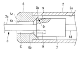
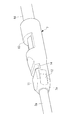
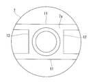
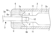
- FIG. 2 is an enlarged longitudinal sectional view of a distal end portion showing a state where an electrode member of the high-frequency treatment instrument in FIG. It is a perspective view which shows the electrode member of the high frequency treatment tool of FIG. It is a front view which shows the relationship between the electrode front-end
- the high-frequency treatment instrument 1 is a treatment instrument in which a distal end is introduced into a body through a channel provided in an insertion portion of an endoscope, for example, as shown in FIG.
- a liquid feeding means 5 for discharging liquid from the distal end of the sheath 2 via the inner hole (flow path) 2a of the sheath 2.
- a plug-like tip member 6 is fixed to the tip of the sheath 2 so as to close the inner hole 2a.
- the tip member 6 is provided with a through hole 6 a that penetrates in the longitudinal axis direction and penetrates the electrode member 3 movably.
- the through-hole 6a has a circular cross section, and a tapered inner surface 6b having a conical inner surface tapering toward the distal end side is provided on the base end side thereof.
- the sheath 2 and the tip member 6 are made of an electrically insulating material.
- the electrode member 3 is made of a conductive material.
- the electrode member 3 includes a columnar portion 3a having a circular cross section that is sufficiently smaller in diameter than the through-hole 6a, and a triangular plate electrode tip that is provided at the tip of the columnar portion 3a and extends radially outward in the radial direction.
- the stopper portion 7 has a tapered surface 7a in a shape complementary to the tapered inner surface 6b on the tip side.
- the taper surface 7a is provided with groove-like recesses 9 that are recessed inward in the radial direction and extending in the longitudinal axis direction at three locations spaced in the circumferential direction. As shown in FIG. 3, each concave portion 9 is provided at a circumferential position corresponding to the center of each side of the triangular electrode tip 3b.
- the electrode tip portion 3b has a shape in which the circumscribed circle A is larger than the diameter of the through hole 6a and the inscribed circle B is smaller than the diameter of the through hole 6a.
- the dimension of the circumscribed circle A is ⁇ 1.2
- the dimension of the through hole 6a is ⁇ 0.8.
- the electrode member 3 protrudes forward from the tip surface 6 c of the tip member 6, and the stopper portion 7.
- the taper surface 7a abuts against the taper inner surface 6b of the tip member 6 to restrict further advancement.
- the tapered surface 7a having a shape complementary to the tapered inner surface 6b is brought into close contact with the tapered inner surface 6b by surface contact, so that the electrode member 3 is firmly supported by the tip member 6.
- the taper surface 7a concentric with the columnar portion 3a of the electrode member 3 is brought into close contact with the tapered inner surface 6b connected to the through hole 6a, so that the electrode member 3 can be aligned with the central axis with respect to the through hole 6a (centering). To be).
- the operation section 4 includes a handle 4b having a finger hooking hole 4a attached to the proximal end side of the sheath 2, a movable section 4c provided so as to be movable in the longitudinal axis direction of the sheath 2 with respect to the handle 4b, and the sheath 2 And a wire 4d made of a conductive material for connecting the movable part 4c and the electrode member 3 to each other.
- reference numeral 4e denotes a finger hole provided in the movable portion 4c.
- the movable portion 4c When the movable portion 4c is moved toward the distal end side of the sheath 2 with respect to the handle 4b, the pressing force is transmitted to the electrode member 3 through the wire 4d, and the electrode member 3 is moved in the direction of moving forward with respect to the distal end member 6. It is like that.
- the movable portion 4c When the movable portion 4c is moved to the proximal end side of the sheath 2 with respect to the handle 4b, the traction force is transmitted to the electrode member 3 through the wire 4d, and the electrode member 3 is drawn into the through hole 6a of the distal end member 6. It can be retracted in the direction.
- a power source (not shown) is connected to the proximal end side of the wire 4d so that a high-frequency current can be supplied to the electrode member 3 through the wire 4d.
- the handle 4 b is provided with a connection port 8 that communicates with the inner hole 2 a of the sheath 2.
- the liquid feeding means 5 is a syringe or a pump connected to the connection port 8, and a liquid such as physiological saline is fed into the inner hole 2 a of the sheath 2 by the operation of the liquid feeding means 5.
- the operation unit 4 is operated to maximize the electrode member 3 as shown in FIG.
- the sheath 2 is introduced into the body from the distal end side through the channel of the insertion portion of the endoscope, and the distal end of the sheath 2 is projected from the distal end of the insertion portion of the endoscope.
- the operator performs the treatment while confirming the image acquired by the endoscope on the monitor.
- the electrode member 3 is retracted to the maximum, only the electrode tip 3b of the electrode member 3 is exposed on the tip surface 6c of the tip member 6, so that a high-frequency current is applied to the electrode member 3 in this state.
- the tissue is not deeply cut, and so-called marking can be performed in which only the tissue surface is cauterized.
- the operator removes the electrode member 3 by energizing the electrode member 3 by pressing the distal end surface 6c of the distal end member 6 against a plurality of locations surrounding a portion that is supposed to be a lesion to be excised in the endoscopic image displayed on the monitor.
- a mark surrounding the periphery of the lesion site to be formed can be formed, which can be used as a measure for subsequent treatment.
- the operation unit 4 is operated to cause the electrode member 3 to protrude from the distal end surface 6c of the distal end member 6 as shown in FIG. Is inserted to the vicinity of the submucosa below the lesion site.
- the operation unit 4 is operated to bring the electrode member 3 to the maximum retracted state, and the liquid feeding means 5 is operated to discharge a liquid such as physiological saline from the opening 10 of the distal end surface 6c. As a result, the liquid is locally injected into the submucosal layer, and the lesion site is lifted.
- the sheath 2 is extracted from the submucosal layer, the electrode member 3 is protruded by operating the operation unit 4 again, and the tissue around the lesion site is incised using the mark formed by the marking as a guide. Go. If there is bleeding in the middle of the incision, it can be cleaned by operating the liquid feeding means 5 to release a liquid such as physiological saline from the opening 10 of the distal end surface 6 c of the distal end member 6.
- the taper surface 7 a of the stopper portion 7 becomes the taper inner surface of the tip member 6.
- the electrode member 3 is fixed in a state of being centered with respect to the through hole 6a in close contact with 6b. Even when the taper surface 7a and the taper inner surface 6b are in close contact with each other, the space before and after the stopper portion 7 is maintained in communication with each other by the recess 9 provided in the taper surface 7a.
- the liquid feeding means 5 When the liquid feeding means 5 is operated in this state, the liquid sent through the inner hole 2a of the sheath 2 passes through the gap C formed by the concave portion 9 between the tapered surface 7a and the tapered inner surface 6b. In addition, it is discharged forward of the tip member 6 through a cylindrical gap C between the columnar portion 3a and the through hole 6a.
- a force that vibrates the columnar portion 3a is applied by the flow of fluid flowing through the gap C between the columnar portion 3a and the through-hole 6a, but the electrode member 3 is attached to the tip end by bringing the tapered surface 7a into close contact with the tapered inner surface 6b. Since it is firmly supported by the member 6, the vibration of the columnar part 3 a is suppressed to be small, and the fluid can be stably discharged in front of the tip member 6.
- the columnar portion 3a is supported so as not to vibrate due to the close contact between the tapered surface 7a and the tapered inner surface 6b.
- a sufficiently large flow area between 6a and the columnar portion 3a can be ensured, and a large amount of fluid can be smoothly discharged. Thereby, bleeding can be washed out more reliably and quickly.
- the through-hole 6a itself is formed in a simple circular cross section having an inner diameter sufficiently larger than the outer diameter of the columnar portion 3a. There is also an advantage that it can be manufactured easily.
- the tip member 6 is again inserted into the mucosa.
- the liquid is locally injected by pressing against the lower layer. Also in this case, it is possible to prevent the electrode member 3 from piercing the tissue more than necessary by retracting the electrode member 3 to the maximum and discharging the liquid.
- the high-frequency treatment device 1 even if the electrode member 3 is retracted to the maximum and the electrode tip portion 3b is abutted against the tip surface 6c of the tip member 6, a large diameter is obtained. Since the through hole 6a protrudes outward in the radial direction of the triangular electrode tip 3b, the liquid can be discharged from the opening 10. In particular, since the phase of the concave portion 9 provided in the tapered surface 7a and the portion (small diameter portion) in which the protruding amount in the radial direction of the electrode tip portion 3b is small coincident, it has flowed through the concave portion 9 The fluid can be easily discharged forward without being completely blocked by the electrode tip 3b.
- a triangular flat plate is used as the electrode tip 3b.
- the electrode tip 3b is not limited to this, and is not limited to a quadrangular or more polygonal shape, a star shape, or an elliptical shape.
- the circumscribed circle A of these shapes is larger than the diameter of the through hole 6a and the inscribed circle B is smaller than the diameter of the through hole 6a, any shape may be adopted.
- the stopper portion 7 having the tapered surface 7a in surface contact with the tapered inner surface 6b is exemplified, but instead of this, as shown in FIGS. 5 and 6 instead of the tapered surface 7a.
- a rotating body shape such as a cylindrical edge 7b or a spherical surface 7c that makes line contact in an annular shape.
- a groove-like recess 9 that allows fluid to flow between the taper inner surface 6b and the taper surface 7a is provided on the taper surface 7a side, but instead, as shown in FIG.
- the recess 9 may be provided on the tapered inner surface 6b side.
- a groove-shaped one is adopted as the concave portion 9 of the stopper portion 7, but the present invention is not limited to this, and as shown in FIGS. 8 and 9, the longitudinal direction of the sheath 2 A portion including the D-cut portion 11 and the grooves 12 provided at equal intervals around the longitudinal axis of the sheath 2 may be employed.
- Reference numeral 13 is a hole provided for brazing the wire 4 d to the stopper portion 7, and reference numeral 14 is a hole provided for brazing the columnar portion 3 a to the stopper portion 7.
- a gap E is formed between the tapered surface 7a and the tapered inner surface 6a by the D-cut portion 11, and a gap F is formed between the tapered surface 7a and the tapered inner surface 6a by the groove 12. It is supposed to be formed.
- the gap E formed by the D-cut portion 11 having a larger groove width than the groove 12 has a larger flow rate per unit time than the gap F formed by the groove 12, and therefore, the unit using the entire circumference of the stopper portion 7. The total flow rate per hour can be increased.
Landscapes
- Health & Medical Sciences (AREA)
- Life Sciences & Earth Sciences (AREA)
- Surgery (AREA)
- Engineering & Computer Science (AREA)
- Public Health (AREA)
- Nuclear Medicine, Radiotherapy & Molecular Imaging (AREA)
- General Health & Medical Sciences (AREA)
- Physics & Mathematics (AREA)
- Veterinary Medicine (AREA)
- Biomedical Technology (AREA)
- Heart & Thoracic Surgery (AREA)
- Medical Informatics (AREA)
- Molecular Biology (AREA)
- Animal Behavior & Ethology (AREA)
- Otolaryngology (AREA)
- Plasma & Fusion (AREA)
- Cardiology (AREA)
- Neurology (AREA)
- Neurosurgery (AREA)
- Biophysics (AREA)
- Optics & Photonics (AREA)
- Pathology (AREA)
- Radiology & Medical Imaging (AREA)
- Surgical Instruments (AREA)
Abstract
細長い筒状のシース(2)と、該シース(2)内に長手軸方向に進退可能に配置され、高周波電流が供給される直棒状の電極部材(3)と、シース(2)の先端に配置され、電極部材(3)を貫通させる貫通孔(6a)を有する先端部材(6)と、シース(2)の基端側に接続される送液手段(5)とを備え、電極部材(3)が、この先端に設けられ径方向外方に放射状に延びる電極先端部(3b)と、先端部材(6)よりも基端側に配置される略回転体形状のストッパ部(7)とを備え、先端部材(6)は、電極部材(3)が最大限に先端側に移動させられたときに、ストッパ部(7)を長手軸方向に突き当てる、先端に向かって先細になるテーパ内面(6b)を備え、該テーパ内面(6b)またはストッパ部(7)のいずれかに、相互に突き当たった状態で、液体を流通させることができる流路(2a)を構成する凹部(9)が設けられている高周波処置具(1)を提供する。
Description
本発明は、高周波処置具に関する。
従来、高周波電流を通電して粘膜等の生体組織を処置する高周波処置具が知られている(例えば、特許文献1参照。)。
この高周波処置具は、シースの先端に設けられた電気絶縁性のキャップ部材の貫通孔に、軸方向に進退可能に棒状電極部を挿入配置し、シース内を送液されてきた液体をキャップ部材の送液開口を介して前方に放出することができる構造を有している。
この高周波処置具は、シースの先端に設けられた電気絶縁性のキャップ部材の貫通孔に、軸方向に進退可能に棒状電極部を挿入配置し、シース内を送液されてきた液体をキャップ部材の送液開口を介して前方に放出することができる構造を有している。
棒状電極部の先端には放射状に拡がる先端部が設けられているため、キャップ部材の正面視において送液開口の少なくとも一部が先端部の外側に露呈するように形成することで、送液開口から放出される液体が棒状電極部の先端部の裏側で遮られることを防止している。そして、特許文献1の高周波処置具では、送液開口は、棒状電極部に近接して支持する小径部分と、先端部の外側に露呈する大径部分とを有する非円形に構成されている。
しかしながら、キャップ部材は極めて小さく精密な加工が必要とされる部品であるため、非円形の送液開口を精密に形成することは容易ではない。逆に、送液開口を加工容易な円形等の単純な形状に形成する場合には、液体を真っ直ぐ前方に放出するために、平面視で先端部の外側に露呈するように口径を大きくする必要があるが、このようにすると棒状電極部を前方に突出させた状態での支持が失われ、棒状電極部と送液開口の中心軸とが合いにくくなるという不都合がある。
本発明は、上述した事情に鑑みてなされたものであって、円滑な送液と電極の安定的な支持を両立し得る製造容易な高周波処置具を提供することを目的としている。
上記目的を達成するために、本発明は以下の手段を提供する。
本発明の一態様は、体内に挿入される細長い筒状のシースと、該シース内に長手軸方向に進退可能に配置され、高周波電流が供給される直棒状の電極部材と、前記シースの先端に配置され、前記電極部材を貫通させる貫通孔を有する先端部材と、前記シースの基端側に接続され、該シースに形成された流路および該流路に連絡する前記貫通孔と前記電極部材との隙間を介して前記シースの長手軸方向前方に液体を放出させる送液手段とを備え、前記電極部材が、該電極部材の先端に設けられ径方向外方に放射状に延びる電極先端部と、前記先端部材よりも基端側に配置され前記電極部材の中心軸を中心とする略回転体形状のストッパ部とを備え、前記先端部材は、前記電極部材が最大限に先端側に移動させられたときに、前記ストッパ部を前記長手軸方向に突き当てる、先端に向かって先細になるテーパ内面を備え、該テーパ内面または前記ストッパ部のいずれかに、相互に突き当たった状態で、前記液体を流通させることができる流路を構成する凹部が設けられ、前記電極先端部が周方向の少なくとも一部に径方向に窪む小径部を備え、前記凹部が前記小径部と同一の周方向位置に設けられている高周波処置具である。
本発明の一態様は、体内に挿入される細長い筒状のシースと、該シース内に長手軸方向に進退可能に配置され、高周波電流が供給される直棒状の電極部材と、前記シースの先端に配置され、前記電極部材を貫通させる貫通孔を有する先端部材と、前記シースの基端側に接続され、該シースに形成された流路および該流路に連絡する前記貫通孔と前記電極部材との隙間を介して前記シースの長手軸方向前方に液体を放出させる送液手段とを備え、前記電極部材が、該電極部材の先端に設けられ径方向外方に放射状に延びる電極先端部と、前記先端部材よりも基端側に配置され前記電極部材の中心軸を中心とする略回転体形状のストッパ部とを備え、前記先端部材は、前記電極部材が最大限に先端側に移動させられたときに、前記ストッパ部を前記長手軸方向に突き当てる、先端に向かって先細になるテーパ内面を備え、該テーパ内面または前記ストッパ部のいずれかに、相互に突き当たった状態で、前記液体を流通させることができる流路を構成する凹部が設けられ、前記電極先端部が周方向の少なくとも一部に径方向に窪む小径部を備え、前記凹部が前記小径部と同一の周方向位置に設けられている高周波処置具である。
体内の組織の切断等の処置は、シースに対して電極部材を前進させて電極先端部の突出量を増大させ、電極部材に高周波電流を供給することにより行われる。組織の切断や剥離を行う際に、放射状の電極先端部を周辺組織に引っ掛けることにより、滑らずに安定して処置を行うことができる。
この場合において、電極部材を前進させると、電極部材の基端側に設けられたストッパ部が、シースの先端に配置され電極部材を貫通孔に貫通させている先端部材のテーパ内面に突き当たり、それ以上の前進が制限される。そして、ストッパ部が略回転体形状に形成されていることにより、テーパ内面に突き当たる際に、電極部材を取り囲む各位置においてストッパ部がテーパ内面に同時に突き当たって、電極部材を貫通孔に対してセンタリングした状態に保持することができる。
このとき、テーパ内面またはストッパ部のいずれかに設けられた凹部により、相互に突き当たったテーパ内面とストッパ部との間に流路が構成される。そして、処置を行っている部位において出血が生じた場合には、送液手段を作動させて、シースに形成された流路およびシースの先端に設けられた先端部材の貫通孔と電極部材との隙間を介してシースの長手軸方向前方に液体を放出させることにより、出血部位近傍に液体を放出して洗浄することができる。
また、ストッパ部とテーパ内面が突き当たった状態で凹部によって形成される流路と電極先端部の小径部との位相を常に一致させた状態に保持し、電極先端部が貫通孔に対して長手軸回りに回転しても、流路から放出される液体を常に電極先端部の小径部を経由して真っ直ぐ前方に放出することができる。
この場合においても、電極部材は、電極部材を取り囲む各位置においてテーパ内面とストッパ部を突き当てることによって強固に支持されているので、貫通孔との隙間を液体が流動しても電極先端部が振動しないように保持される。
すなわち、本態様によれば、貫通孔に電極部材を支持させるのではなく、先端部材に設けたテーパ内面と電極部材に設けたストッパ部との当接により、センタリングおよび強固な支持を行うので、貫通孔と電極部材との隙間を十分に大きく確保することができる。その結果、該隙間を経由して前方に放出される液体を、電極先端部に邪魔されることなく、かつ、電極部材を振動させることなく放出することができる。
すなわち、本態様によれば、貫通孔に電極部材を支持させるのではなく、先端部材に設けたテーパ内面と電極部材に設けたストッパ部との当接により、センタリングおよび強固な支持を行うので、貫通孔と電極部材との隙間を十分に大きく確保することができる。その結果、該隙間を経由して前方に放出される液体を、電極先端部に邪魔されることなく、かつ、電極部材を振動させることなく放出することができる。
上記態様においては、前記ストッパ部が、前記テーパ内面と面接触させられるテーパ面を備えていてもよい。
このようにすることで、ストッパ部とテーパ内面との面接触により、電極部材を貫通孔にセンタリングした状態で、先端部材に、より強固に支持することができる。
このようにすることで、ストッパ部とテーパ内面との面接触により、電極部材を貫通孔にセンタリングした状態で、先端部材に、より強固に支持することができる。
上記態様においては、前記貫通孔の先端開口の前記長手軸方向の投影形状が円形であり、前記電極先端部の前記長手軸方向の投影形状が前記先端開口の口径より大きな外接円と前記口径より小さな内接円とを有する非円形であってもよい。
このようにすることで、シースに対して電極部材を最大限に後退させると、円形からなる貫通孔の先端開口に対して、非円形からなる電極先端部の径方向に突出する部分が先端部材の先端面に突き当たって、それ以上の後退が制限される。また、円形からなる貫通孔の先端開口が、非円形からなる電極先端部の径方向に突出する部分においては、先端開口から放出される液体が電極先端部によって完全には遮られることなく真っ直ぐ前方に放出されやすくなる。
このようにすることで、シースに対して電極部材を最大限に後退させると、円形からなる貫通孔の先端開口に対して、非円形からなる電極先端部の径方向に突出する部分が先端部材の先端面に突き当たって、それ以上の後退が制限される。また、円形からなる貫通孔の先端開口が、非円形からなる電極先端部の径方向に突出する部分においては、先端開口から放出される液体が電極先端部によって完全には遮られることなく真っ直ぐ前方に放出されやすくなる。
上記態様においては、前記ストッパ部に前記凹部が形成されていてもよい。
このようにすることで、ストッパ部とテーパ内面が突き当たった状態で凹部によって形成される流路と電極先端部との位相を常に一定に保持し、電極先端部が貫通孔に対して長手軸回りに回転しても、流路が電極先端部によって変化することが防止される。
このようにすることで、ストッパ部とテーパ内面が突き当たった状態で凹部によって形成される流路と電極先端部との位相を常に一定に保持し、電極先端部が貫通孔に対して長手軸回りに回転しても、流路が電極先端部によって変化することが防止される。
上記態様においては、前記小径部が、周方向に等間隔をあけて複数設けられ、前記凹部が、各前記小径部に対応する位置に設けられていてもよい。
このようにすることで、凹部および小径部を経由して電極先端部の前方に真っ直ぐ放出される液体の流れを電極先端部の周方向に偏らせることなく、周方向に均等に分布させ、より真っ直ぐ前方に液体を放出することができる。
このようにすることで、凹部および小径部を経由して電極先端部の前方に真っ直ぐ放出される液体の流れを電極先端部の周方向に偏らせることなく、周方向に均等に分布させ、より真っ直ぐ前方に液体を放出することができる。
本発明によれば、円滑な送液と電極の安定的な支持を両立し、かつ容易に製造することができるという効果を奏する。
本発明の一実施形態に係る高周波処置具1について、図面を参照して以下に説明する。
本実施形態に係る高周波処置具1は、例えば、内視鏡の挿入部に設けられたチャネルを介して先端が体内に導入される処置具であって、図1に示されるように、チャネル内に挿入可能な細長い円筒状に形成され、可撓性を有するシース2と、該シース2の先端において進退させられる電極部材3と、該電極部材3をシース2の基端側において押し引きする操作部4と、シース2の内孔(流路)2aを経由してシース2の先端から液体を放出させる送液手段5とを備えている。
本実施形態に係る高周波処置具1は、例えば、内視鏡の挿入部に設けられたチャネルを介して先端が体内に導入される処置具であって、図1に示されるように、チャネル内に挿入可能な細長い円筒状に形成され、可撓性を有するシース2と、該シース2の先端において進退させられる電極部材3と、該電極部材3をシース2の基端側において押し引きする操作部4と、シース2の内孔(流路)2aを経由してシース2の先端から液体を放出させる送液手段5とを備えている。
シース2の先端には内孔2aを閉塞するようにプラグ状の先端部材6が固定されている。先端部材6には、図2に示されるように、長手軸方向に貫通し電極部材3を移動可能に貫通させる貫通孔6aが設けられている。貫通孔6aは、円形の横断面を有しており、その基端側には、先端側に向かって先細になる円錐内面状のテーパ内面6bが設けられている。シース2および先端部材6は電気絶縁性の材料によって構成されている。
電極部材3は導電性材料により構成されている。電極部材3は、貫通孔6aよりも十分に径寸法の小さい横断面円形の柱状部3aと、該柱状部3aの先端に設けられ、径方向外方に放射状に延びる3角形平板状の電極先端部3bと、柱状部3aの基端に設けられ、柱状部3aより大径の横断面形状を有し、柱状部3aと同心の円柱状に構成されたストッパ部7とを備えている。ストッパ部7の先端側にはテーパ内面6bと相補的な形状のテーパ面7aを有している。
テーパ面7aには、径方向内方に窪み、長手軸方向に延びる溝状の凹部9が、周方向に間隔をあけて3カ所に設けられている。各凹部9は、図3に示されるように、3角形の電極先端部3bの各辺の中央に対応する周方向位置に設けられている。
電極先端部3bは、図4に示されるように、外接円Aが貫通孔6aの口径より大きく、内接円Bが貫通孔6aの口径より小さくなる形状を有している。好ましくは、外接円Aの寸法がφ1.2、貫通孔6aの寸法がφ0.8である。これにより、電極部材3を先端部材6に対して最大限に基端側に移動させると、電極部材3の大部分がシース2内に収容され、電極先端部3bの背面が、先端部材6の先端面6cに突き当たってそれ以上の後退を規制するようになっている。このとき、円形の貫通孔6aは、図4に示されるように、電極先端部3bによって完全に閉塞されることなく、電極先端部3bの径方向外方にはみ出して、開口10により部分的に開口するようになっている。
また、図1に示されるように、電極先端部3bを先端部材6に対して最大限に先端側に移動させると、電極部材3は先端部材6の先端面6cから前方に突出し、ストッパ部7のテーパ面7aが先端部材6のテーパ内面6bに突き当たって、それ以上の前進を規制するようになっている。このとき、テーパ内面6bと相補的な形状のテーパ面7aは面接触によりテーパ内面6bに密着し、電極部材3が先端部材6に強固に支持されるようになっている。また、貫通孔6aに接続するテーパ内面6bに、電極部材3の柱状部3aと同心のテーパ面7aを密着させることにより、電極部材3が貫通孔6aに対して中心軸を一致させられる(センタリングされる)ようになっている。
操作部4は、シース2の基端側に取り付けられる指かけ孔4aを有するハンドル4bと、該ハンドル4bに対してシース2の長手軸方向に移動可能に設けられた可動部4cと、シース2の内孔2a内に配置され可動部4cと電極部材3とを連結する導電性材料からなるワイヤ4dとを備えている。図中符号4eは可動部4cに設けられた指かけ孔である。
ハンドル4bに対して可動部4cをシース2の先端側に移動させると押圧力がワイヤ4dを介して電極部材3に伝達され、電極部材3が先端部材6に対して前進する方向に移動させられるようになっている。また、ハンドル4bに対して可動部4cをシース2の基端側に移動させると、牽引力がワイヤ4dを介して電極部材3に伝達され、電極部材3が先端部材6の貫通孔6aに引き込まれる方向に後退させられるようになっている。
ワイヤ4dの基端側には図示しない電源が接続されており、ワイヤ4dを介して電極部材3に高周波電流を供給することができるようになっている。
ワイヤ4dの基端側には図示しない電源が接続されており、ワイヤ4dを介して電極部材3に高周波電流を供給することができるようになっている。
ハンドル4bには、シース2の内孔2aに連絡する接続口8が設けられている。
送液手段5は、接続口8に接続されるシリンジあるいはポンプ等であり、送液手段5の作動によって生理食塩水のような液体をシース2の内孔2aに送り込むようになっている。
送液手段5は、接続口8に接続されるシリンジあるいはポンプ等であり、送液手段5の作動によって生理食塩水のような液体をシース2の内孔2aに送り込むようになっている。
このように構成された本実施形態に係る高周波処置具1の作用について、以下に説明する。
本実施形態に係る高周波処置具1を使用して、内視鏡的粘膜下層剥離術を行うには、操作部4を操作して、図4に示されるように、電極部材3を最大限に後退させた状態で、内視鏡の挿入部のチャネルを介してシース2を先端側から体内に導入していき、内視鏡の挿入部の先端からシース2の先端を突出させる。
本実施形態に係る高周波処置具1を使用して、内視鏡的粘膜下層剥離術を行うには、操作部4を操作して、図4に示されるように、電極部材3を最大限に後退させた状態で、内視鏡の挿入部のチャネルを介してシース2を先端側から体内に導入していき、内視鏡の挿入部の先端からシース2の先端を突出させる。
これにより、シース2の先端部分が内視鏡の視界に入るので、操作者は内視鏡により取得された画像をモニタで確認しながら、処置を行う。電極部材3を最大限に後退させた状態では、電極部材3の電極先端部3bのみが先端部材6の先端面6cに露出しているので、この状態で電極部材3に高周波電流を印加しても組織が深く切り込まれることはなく、組織表面のみを焼酌するいわゆるマーキングを行うことができる。
すなわち、操作者はモニタに表示された内視鏡画像において切除すべき病変と思われる部位を取り囲む複数箇所に先端部材6の先端面6cを押し当てて電極部材3に通電することにより、切除すべき病変部位の周囲を取り囲むマークを形成することができ、その後の処置の目安とすることができる。
この後に、操作部4を操作して、図3に示されるように、電極部材3を先端部材6の先端面6cから突出させ、高周波電流を印加することにより、組織を切開して先端部材6を病変部位の下の粘膜下層近傍まで刺し入れる。次いで、操作部4を操作して電極部材3を最大限に後退させた状態とし、送液手段5を作動させて生理食塩水等の液体を先端面6cの開口10から放出させる。これにより、液体が粘膜下層に局注され、病変部位が浮上させられた状態となる。
この状態で、シース2を粘膜下層から抜き出し、再度、操作部4を操作して電極部材3を突出させた状態として、マーキングにより形成されたマークを目安として病変部位の周囲の組織を切開していく。
切開途中で出血があった場合には、送液手段5を作動させて生理食塩水等の液体を先端部材6の先端面6cの開口10から放出させることにより洗浄することができる。
切開途中で出血があった場合には、送液手段5を作動させて生理食塩水等の液体を先端部材6の先端面6cの開口10から放出させることにより洗浄することができる。
この場合において、シース2に対して電極部材3を最大限に前進させ、電極先端部3bを先端部材6の先端面6cから突出させると、ストッパ部7のテーパ面7aが先端部材6のテーパ内面6bに密着して、電極部材3が貫通孔6aに対してセンタリングされた状態に固定される。そして、テーパ面7aとテーパ内面6bとが密着させられた状態でも、テーパ面7aに設けられた凹部9によって、ストッパ部7を挟んだ前後の空間が連絡した状態に維持される。
この状態で、送液手段5を作動させると、シース2の内孔2aを介して送られてきた液体が、凹部9によってテーパ面7aとテーパ内面6bとの間に形成された隙間Cを経由し、さらに、柱状部3aと貫通孔6aとの間の円筒状の隙間Cを経由して、先端部材6の前方に放出される。
柱状部3aと貫通孔6aとの間の隙間Cを流動する流体の流れによって柱状部3aを振動させる力が作用するが、テーパ面7aをテーパ内面6bに密着させることで、電極部材3が先端部材6に強固に支持されているので、柱状部3aの振動が小さく抑制され、先端部材6の前方に流体を安定して放出することができる。
すなわち、貫通孔6aの内径を柱状部3aの外径に対して十分に大きくしても、テーパ面7aとテーパ内面6bとの密着により柱状部3aが振動しないように支持されるので、貫通孔6aと柱状部3aとの間の流動面積を十分に大きく確保することができ、大流量の流体を円滑に放出することができるという利点がある。これにより、出血をより確実に素早く洗い流すことができる。
また、貫通孔6aによって柱状部3aを径方向に振動しないように支持しなくて済むので、貫通孔6a自体を柱状部3aの外径よりも十分に大きな内径の簡易な横断面円形に形成することができ、容易に製造することができるという利点もある。
また、貫通孔6aによって柱状部3aを径方向に振動しないように支持しなくて済むので、貫通孔6a自体を柱状部3aの外径よりも十分に大きな内径の簡易な横断面円形に形成することができ、容易に製造することができるという利点もある。
また、病変部位の周囲の組織を切開する途中で、粘膜下層に局注した液体が他の部位に吸収される等して、病変部位が沈んできた場合には、先端部材6を再度、粘膜下層に押し当てて液体を局注することが行われる。この場合にも、電極部材3を最大限に後退させて液体を吐出させることにより電極部材3が必要以上に組織に刺さらないようにすることができる。
この場合においても、本実施形態に係る高周波処置具1によれば、電極部材3を最大限に後退させて、電極先端部3bを先端部材6の先端面6cに突き当てても、大きな口径の貫通孔6aが3角形の電極先端部3bの径方向外方にはみ出して開口しているので、その開口10から液体を放出することができる。特に、テーパ面7aに設けられた凹部9と、電極先端部3bの径方向への突出量が小さい部分(小径部)との位相が一致しているので、凹部9を経由して流動してきた流体を電極先端部3bによって完全には遮られることなく前方に放出しやすくすることができる。
なお、本実施形態においては、電極先端部3bとして、三角形の平板状のものを採用したが、これに限定されるものではなく、4角形以上の多角形状、星形状あるいは楕円形状のように、径方向に突出する部分と窪む部分とを周方向に交互に配列してなる任意の電極先端部3bを採用してもよい。これらの形状の外接円Aが貫通孔6aの口径より大きく、内接円Bが貫通孔6aの口径より小さければ、任意の形状を採用してよい。そして、これらの場合に径方向に窪む部分(小径部)に対応する位置に溝状の凹部9を設けることが好ましい。
また、本実施形態においては、ストッパ部7としてテーパ内面6bに面接触するテーパ面7aを有するものを例示したが、これに代えて、テーパ面7aではなく、図5および図6に示されるように円柱のエッジ7bあるいは球面7c等の回転体形状を有し、円環状に線接触するものを採用してもよい。
また、テーパ内面6bにテーパ面7aを密着させた状態でも両者間に流体を流通させる溝状の凹部9をテーパ面7a側に設けることとしたが、これに代えて、図7に示されるように、凹部9をテーパ内面6b側に設けることにしてもよい。
また、テーパ内面6bにテーパ面7aを密着させた状態でも両者間に流体を流通させる溝状の凹部9をテーパ面7a側に設けることとしたが、これに代えて、図7に示されるように、凹部9をテーパ内面6b側に設けることにしてもよい。
また、本実施形態においては、ストッパ部7の凹部9として、溝状のものを採用したが、これに限られるものではなく、図8および図9に示されるように、シース2の長手軸方向に沿ってDカット部11と、シース2の長手軸回りにDカット部11を挟んで等間隔に設けられた溝12とからなるものを採用してもよい。符号13は、ストッパ部7にワイヤ4dをロウ付けするために設けられた穴であり、符号14は、ストッパ部7に柱状部3aをロウ付けするために設けられた穴である。
この場合には、図10に示されるように、Dカット部11によってテーパ面7aとテーパ内面6aとの間に隙間Eが、溝12によってテーパ面7aとテーパ内面6aとの間に隙間Fが形成されるようになっている。これにより、溝12よりも溝幅の大きいDカット部11が形成する隙間Eは、溝12が形成する隙間Fよりも単位時間当たりの流量が多いため、ストッパ部7の全周を用いて単位時間当たりの総流量を増大させることができる。
1 高周波処置具
2 シース
2a 内孔(流路)
3 電極部材
3b 電極先端部
5 送液手段
6 先端部材
6a 貫通孔
6b テーパ内面
7 ストッパ部
7a テーパ面
9 凹部
C 隙間
2 シース
2a 内孔(流路)
3 電極部材
3b 電極先端部
5 送液手段
6 先端部材
6a 貫通孔
6b テーパ内面
7 ストッパ部
7a テーパ面
9 凹部
C 隙間
Claims (5)
- 体内に挿入される細長い筒状のシースと、
該シース内に長手軸方向に進退可能に配置され、高周波電流が供給される直棒状の電極部材と、
前記シースの先端に配置され、前記電極部材を貫通させる貫通孔を有する先端部材と、
前記シースの基端側に接続され、該シースに形成された流路および該流路に連絡する前記貫通孔と前記電極部材との隙間を介して前記シースの長手軸方向前方に液体を放出させる送液手段とを備え、
前記電極部材が、該電極部材の先端に設けられ径方向外方に放射状に延びる電極先端部と、前記先端部材よりも基端側に配置され前記電極部材の中心軸を中心とする略回転体形状のストッパ部とを備え、
前記先端部材は、前記電極部材が最大限に先端側に移動させられたときに、前記ストッパ部を前記長手軸方向に突き当てる、先端に向かって先細になるテーパ内面を備え、
該テーパ内面または前記ストッパ部のいずれかに、相互に突き当たった状態で、前記液体を流通させることができる流路を構成する凹部が設けられ、
前記電極先端部が周方向の少なくとも一部に径方向に窪む小径部を備え、
前記凹部が前記小径部と同一の周方向位置に設けられている高周波処置具。 - 前記ストッパ部が、前記テーパ内面と面接触させられるテーパ面を備える請求項1に記載の高周波処置具。
- 前記貫通孔の先端開口の前記長手軸方向の投影形状が円形であり、前記電極先端部の前記長手軸方向の投影形状が前記先端開口の口径より大きな外接円と前記口径より小さな内接円とを有する非円形である請求項1または請求項2に記載の高周波処置具。
- 前記ストッパ部に前記凹部が形成されている請求項1から請求項3のいずれか一項に記載の高周波処置具。
- 前記小径部が、周方向に等間隔をあけて複数設けられ、
前記凹部が、各前記小径部に対応する位置に設けられている請求項1から請求項4のいずれか一項に記載の高周波処置具。
Priority Applications (5)
| Application Number | Priority Date | Filing Date | Title |
|---|---|---|---|
| CN202110826776.9A CN113648049B (zh) | 2015-06-18 | 2016-06-02 | 高频处置器具 |
| CN201680034881.6A CN107683119B (zh) | 2015-06-18 | 2016-06-02 | 高频处置器具 |
| EP16811453.6A EP3311767B1 (en) | 2015-06-18 | 2016-06-02 | High-frequency treatment tool |
| JP2017523013A JP6205529B2 (ja) | 2015-06-18 | 2016-06-02 | 高周波処置具 |
| US15/840,343 US10631924B2 (en) | 2015-06-18 | 2017-12-13 | High-frequency treatment tool |
Applications Claiming Priority (2)
| Application Number | Priority Date | Filing Date | Title |
|---|---|---|---|
| JP2015122945 | 2015-06-18 | ||
| JP2015-122945 | 2015-06-18 |
Related Child Applications (1)
| Application Number | Title | Priority Date | Filing Date |
|---|---|---|---|
| US15/840,343 Continuation US10631924B2 (en) | 2015-06-18 | 2017-12-13 | High-frequency treatment tool |
Publications (1)
| Publication Number | Publication Date |
|---|---|
| WO2016203978A1 true WO2016203978A1 (ja) | 2016-12-22 |
Family
ID=57545582
Family Applications (1)
| Application Number | Title | Priority Date | Filing Date |
|---|---|---|---|
| PCT/JP2016/066463 WO2016203978A1 (ja) | 2015-06-18 | 2016-06-02 | 高周波処置具 |
Country Status (5)
| Country | Link |
|---|---|
| US (1) | US10631924B2 (ja) |
| EP (1) | EP3311767B1 (ja) |
| JP (1) | JP6205529B2 (ja) |
| CN (2) | CN113648049B (ja) |
| WO (1) | WO2016203978A1 (ja) |
Cited By (1)
| Publication number | Priority date | Publication date | Assignee | Title |
|---|---|---|---|---|
| WO2021234793A1 (ja) * | 2020-05-18 | 2021-11-25 | オリンパス株式会社 | 処置具、キャップ、及び処置具の製造方法 |
Families Citing this family (2)
| Publication number | Priority date | Publication date | Assignee | Title |
|---|---|---|---|---|
| CN113648049B (zh) * | 2015-06-18 | 2024-02-02 | 奥林巴斯株式会社 | 高频处置器具 |
| CN109700507A (zh) * | 2018-12-28 | 2019-05-03 | 先健科技(深圳)有限公司 | 穿刺装置 |
Citations (4)
| Publication number | Priority date | Publication date | Assignee | Title |
|---|---|---|---|---|
| JP2007044393A (ja) * | 2005-08-12 | 2007-02-22 | Fujinon Corp | 高周波処置具 |
| JP2012070793A (ja) * | 2010-09-27 | 2012-04-12 | Fujifilm Corp | 内視鏡用処置具 |
| JP2012075657A (ja) * | 2010-09-30 | 2012-04-19 | Fujifilm Corp | 内視鏡用処置具 |
| JP5646788B2 (ja) * | 2012-09-12 | 2014-12-24 | オリンパスメディカルシステムズ株式会社 | 高周波ナイフ |
Family Cites Families (26)
| Publication number | Priority date | Publication date | Assignee | Title |
|---|---|---|---|---|
| AU6880598A (en) * | 1997-04-04 | 1998-10-30 | Minnesota Mining And Manufacturing Company | Method and apparatus for controlling contact of biomedical electrodes with patient skin |
| JP4068989B2 (ja) | 2003-02-20 | 2008-03-26 | オリンパス株式会社 | 高周波処置具 |
| JP3923022B2 (ja) | 2003-02-28 | 2007-05-30 | オリンパス株式会社 | 内視鏡用処置具 |
| JP4315725B2 (ja) * | 2003-04-17 | 2009-08-19 | オリンパス株式会社 | 高周波ナイフ |
| FR2870346B1 (fr) * | 2004-05-17 | 2006-09-08 | Millipore Corp | Cellule de mesure de conductivite d'un fluide |
| JP4836492B2 (ja) | 2005-05-25 | 2011-12-14 | 富士フイルム株式会社 | 高周波処置具及び高周波処置具を用いた粘膜剥離方法 |
| US8372071B2 (en) * | 2005-08-12 | 2013-02-12 | Fujinon Corporation | High-frequency treatment tool |
| JP4471125B2 (ja) * | 2006-06-23 | 2010-06-02 | 富士フイルム株式会社 | 高周波処置具 |
| CN200948137Y (zh) * | 2006-08-12 | 2007-09-19 | 窦会芹 | 心电图吸杯电极多用夹 |
| WO2008026689A1 (fr) * | 2006-08-30 | 2008-03-06 | Jichi Medical University | Outil de traitement pour endoscope |
| US8460285B2 (en) * | 2006-12-29 | 2013-06-11 | St. Jude Medical, Atrial Fibrillation Division, Inc. | Ablation catheter electrode having multiple thermal sensors and method of use |
| JP2009112788A (ja) | 2007-10-17 | 2009-05-28 | Takashi Toyonaga | 高周波処置具 |
| US8216225B2 (en) * | 2007-12-21 | 2012-07-10 | St. Jude Medical, Atrial Fibrillation Division, Inc. | Irrigated ablation electrode assembly having a polygonal electrode |
| JP2009247696A (ja) * | 2008-04-08 | 2009-10-29 | Olympus Medical Systems Corp | 高周波処置具 |
| JP2010046200A (ja) * | 2008-08-20 | 2010-03-04 | Fujinon Corp | 高周波処置具 |
| US20130218149A1 (en) * | 2010-07-08 | 2013-08-22 | Given Imaging Ltd. | Cryo-therapy spray device |
| WO2012097130A2 (en) * | 2011-01-12 | 2012-07-19 | Perfect Point Edm Corporation | Adaptive flushing for workpiece erosion |
| WO2012124653A1 (ja) * | 2011-03-17 | 2012-09-20 | オリンパスメディカルシステムズ株式会社 | 医療用送液装置及び医療用処置装置 |
| JP3168428U (ja) * | 2011-03-31 | 2011-06-09 | 日本ゼオン株式会社 | バイポーラ型電気処置器具 |
| JP5755121B2 (ja) | 2011-11-30 | 2015-07-29 | Hoya株式会社 | 内視鏡用高周波処置具 |
| JP5654181B2 (ja) | 2012-10-17 | 2015-01-14 | オリンパスメディカルシステムズ株式会社 | 高周波ナイフ |
| JP5775989B1 (ja) | 2013-10-09 | 2015-09-09 | オリンパス株式会社 | 内視鏡用高周波処置具 |
| WO2016021230A1 (ja) * | 2014-08-06 | 2016-02-11 | オリンパス株式会社 | 高周波処置具 |
| EP3222241A4 (en) * | 2014-11-18 | 2018-08-01 | Olympus Corporation | Endoscopic treatment instrument |
| CN204331236U (zh) * | 2014-12-17 | 2015-05-13 | 深圳市帝晶光电股份有限公司 | 一种宽视角液晶显示屏 |
| CN113648049B (zh) * | 2015-06-18 | 2024-02-02 | 奥林巴斯株式会社 | 高频处置器具 |
-
2016
- 2016-06-02 CN CN202110826776.9A patent/CN113648049B/zh active Active
- 2016-06-02 WO PCT/JP2016/066463 patent/WO2016203978A1/ja active Application Filing
- 2016-06-02 CN CN201680034881.6A patent/CN107683119B/zh active Active
- 2016-06-02 JP JP2017523013A patent/JP6205529B2/ja active Active
- 2016-06-02 EP EP16811453.6A patent/EP3311767B1/en active Active
-
2017
- 2017-12-13 US US15/840,343 patent/US10631924B2/en active Active
Patent Citations (4)
| Publication number | Priority date | Publication date | Assignee | Title |
|---|---|---|---|---|
| JP2007044393A (ja) * | 2005-08-12 | 2007-02-22 | Fujinon Corp | 高周波処置具 |
| JP2012070793A (ja) * | 2010-09-27 | 2012-04-12 | Fujifilm Corp | 内視鏡用処置具 |
| JP2012075657A (ja) * | 2010-09-30 | 2012-04-19 | Fujifilm Corp | 内視鏡用処置具 |
| JP5646788B2 (ja) * | 2012-09-12 | 2014-12-24 | オリンパスメディカルシステムズ株式会社 | 高周波ナイフ |
Non-Patent Citations (1)
| Title |
|---|
| See also references of EP3311767A4 * |
Cited By (1)
| Publication number | Priority date | Publication date | Assignee | Title |
|---|---|---|---|---|
| WO2021234793A1 (ja) * | 2020-05-18 | 2021-11-25 | オリンパス株式会社 | 処置具、キャップ、及び処置具の製造方法 |
Also Published As
| Publication number | Publication date |
|---|---|
| EP3311767B1 (en) | 2023-03-01 |
| EP3311767A4 (en) | 2019-04-10 |
| CN107683119B (zh) | 2021-07-27 |
| JPWO2016203978A1 (ja) | 2017-08-03 |
| CN107683119A (zh) | 2018-02-09 |
| CN113648049B (zh) | 2024-02-02 |
| EP3311767A1 (en) | 2018-04-25 |
| US10631924B2 (en) | 2020-04-28 |
| JP6205529B2 (ja) | 2017-09-27 |
| CN113648049A (zh) | 2021-11-16 |
| US20180110559A1 (en) | 2018-04-26 |
Similar Documents
| Publication | Publication Date | Title |
|---|---|---|
| JP5876194B1 (ja) | 高周波処置具 | |
| KR100595803B1 (ko) | 고주파 나이프 및 내시경 장치 | |
| JP5775989B1 (ja) | 内視鏡用高周波処置具 | |
| JP6205529B2 (ja) | 高周波処置具 | |
| JP5613518B2 (ja) | 内視鏡用処置具 | |
| KR101596716B1 (ko) | 시술장치 | |
| JP2013111308A (ja) | 内視鏡用高周波処置具 | |
| JP2007044393A (ja) | 高周波処置具 | |
| JP2010042155A (ja) | 内視鏡用処置具 | |
| WO2012042984A1 (ja) | 内視鏡用処置具 | |
| JP6227204B1 (ja) | 内視鏡処置具 | |
| WO2016203977A1 (ja) | 高周波処置具 | |
| JP2007068596A (ja) | 高周波処置具 | |
| JP4794214B2 (ja) | 高周波処置具 | |
| JP5019723B2 (ja) | 切開鉗子 | |
| WO2017122608A1 (ja) | 内視鏡用高周波処置具 | |
| JP6655398B2 (ja) | 内視鏡用高周波処置具 | |
| WO2016013255A1 (ja) | 高周波処置具 | |
| KR20070019599A (ko) | 고주파 처치구 |
Legal Events
| Date | Code | Title | Description |
|---|---|---|---|
| 121 | Ep: the epo has been informed by wipo that ep was designated in this application |
Ref document number: 16811453 Country of ref document: EP Kind code of ref document: A1 |
|
| ENP | Entry into the national phase |
Ref document number: 2017523013 Country of ref document: JP Kind code of ref document: A |
|
| NENP | Non-entry into the national phase |
Ref country code: DE |
|
| WWE | Wipo information: entry into national phase |
Ref document number: 2016811453 Country of ref document: EP |