WO2016203796A1 - Système de commande de gestion, dispositif de commande de gestion, et dispositif de terminal embarqué dans un véhicule - Google Patents
Système de commande de gestion, dispositif de commande de gestion, et dispositif de terminal embarqué dans un véhicule Download PDFInfo
- Publication number
- WO2016203796A1 WO2016203796A1 PCT/JP2016/057470 JP2016057470W WO2016203796A1 WO 2016203796 A1 WO2016203796 A1 WO 2016203796A1 JP 2016057470 W JP2016057470 W JP 2016057470W WO 2016203796 A1 WO2016203796 A1 WO 2016203796A1
- Authority
- WO
- WIPO (PCT)
- Prior art keywords
- lane
- section
- travel
- vehicle
- travel permission
- Prior art date
Links
Images


Classifications
-
- G—PHYSICS
- G08—SIGNALLING
- G08G—TRAFFIC CONTROL SYSTEMS
- G08G1/00—Traffic control systems for road vehicles
- G08G1/16—Anti-collision systems
- G08G1/167—Driving aids for lane monitoring, lane changing, e.g. blind spot detection
-
- B—PERFORMING OPERATIONS; TRANSPORTING
- B60—VEHICLES IN GENERAL
- B60R—VEHICLES, VEHICLE FITTINGS, OR VEHICLE PARTS, NOT OTHERWISE PROVIDED FOR
- B60R21/00—Arrangements or fittings on vehicles for protecting or preventing injuries to occupants or pedestrians in case of accidents or other traffic risks
-
- G—PHYSICS
- G08—SIGNALLING
- G08G—TRAFFIC CONTROL SYSTEMS
- G08G1/00—Traffic control systems for road vehicles
-
- G—PHYSICS
- G08—SIGNALLING
- G08G—TRAFFIC CONTROL SYSTEMS
- G08G1/00—Traffic control systems for road vehicles
- G08G1/09—Arrangements for giving variable traffic instructions
- G08G1/0962—Arrangements for giving variable traffic instructions having an indicator mounted inside the vehicle, e.g. giving voice messages
- G08G1/0967—Systems involving transmission of highway information, e.g. weather, speed limits
- G08G1/096708—Systems involving transmission of highway information, e.g. weather, speed limits where the received information might be used to generate an automatic action on the vehicle control
- G08G1/096716—Systems involving transmission of highway information, e.g. weather, speed limits where the received information might be used to generate an automatic action on the vehicle control where the received information does not generate an automatic action on the vehicle control
-
- G—PHYSICS
- G08—SIGNALLING
- G08G—TRAFFIC CONTROL SYSTEMS
- G08G1/00—Traffic control systems for road vehicles
- G08G1/09—Arrangements for giving variable traffic instructions
- G08G1/0962—Arrangements for giving variable traffic instructions having an indicator mounted inside the vehicle, e.g. giving voice messages
- G08G1/0967—Systems involving transmission of highway information, e.g. weather, speed limits
- G08G1/096766—Systems involving transmission of highway information, e.g. weather, speed limits where the system is characterised by the origin of the information transmission
- G08G1/096775—Systems involving transmission of highway information, e.g. weather, speed limits where the system is characterised by the origin of the information transmission where the origin of the information is a central station
-
- G—PHYSICS
- G08—SIGNALLING
- G08G—TRAFFIC CONTROL SYSTEMS
- G08G1/00—Traffic control systems for road vehicles
- G08G1/09—Arrangements for giving variable traffic instructions
- G08G1/0962—Arrangements for giving variable traffic instructions having an indicator mounted inside the vehicle, e.g. giving voice messages
- G08G1/0968—Systems involving transmission of navigation instructions to the vehicle
- G08G1/096855—Systems involving transmission of navigation instructions to the vehicle where the output is provided in a suitable form to the driver
-
- G—PHYSICS
- G08—SIGNALLING
- G08G—TRAFFIC CONTROL SYSTEMS
- G08G1/00—Traffic control systems for road vehicles
- G08G1/09—Arrangements for giving variable traffic instructions
- G08G1/0962—Arrangements for giving variable traffic instructions having an indicator mounted inside the vehicle, e.g. giving voice messages
- G08G1/0968—Systems involving transmission of navigation instructions to the vehicle
- G08G1/0969—Systems involving transmission of navigation instructions to the vehicle having a display in the form of a map
-
- G—PHYSICS
- G08—SIGNALLING
- G08G—TRAFFIC CONTROL SYSTEMS
- G08G1/00—Traffic control systems for road vehicles
- G08G1/16—Anti-collision systems
-
- G—PHYSICS
- G08—SIGNALLING
- G08G—TRAFFIC CONTROL SYSTEMS
- G08G1/00—Traffic control systems for road vehicles
- G08G1/16—Anti-collision systems
- G08G1/166—Anti-collision systems for active traffic, e.g. moving vehicles, pedestrians, bikes
-
- G—PHYSICS
- G08—SIGNALLING
- G08G—TRAFFIC CONTROL SYSTEMS
- G08G1/00—Traffic control systems for road vehicles
- G08G1/20—Monitoring the location of vehicles belonging to a group, e.g. fleet of vehicles, countable or determined number of vehicles
- G08G1/207—Monitoring the location of vehicles belonging to a group, e.g. fleet of vehicles, countable or determined number of vehicles with respect to certain areas, e.g. forbidden or allowed areas with possible alerting when inside or outside boundaries
-
- G—PHYSICS
- G08—SIGNALLING
- G08G—TRAFFIC CONTROL SYSTEMS
- G08G1/00—Traffic control systems for road vehicles
- G08G1/09—Arrangements for giving variable traffic instructions
- G08G1/0962—Arrangements for giving variable traffic instructions having an indicator mounted inside the vehicle, e.g. giving voice messages
- G08G1/0968—Systems involving transmission of navigation instructions to the vehicle
- G08G1/096805—Systems involving transmission of navigation instructions to the vehicle where the transmitted instructions are used to compute a route
- G08G1/096811—Systems involving transmission of navigation instructions to the vehicle where the transmitted instructions are used to compute a route where the route is computed offboard
- G08G1/096822—Systems involving transmission of navigation instructions to the vehicle where the transmitted instructions are used to compute a route where the route is computed offboard where the segments of the route are transmitted to the vehicle at different locations and times
Definitions
- the present invention relates to a control control system, a control control device, and an in-vehicle terminal device, and relates to a control control technology at a work site where autonomously traveling vehicles and manned vehicles are mixedly running.
- Patent Document 1 as a control control technique in an autonomous traveling system of a mine, based on a monitoring result of a traveling state of a traveling road, an entry prohibition region is located in front of one vehicle traveling in one lane of two round-trip lanes. It is set and a travel command is given to drive a part of the opposite lane facing one lane while avoiding the entry prohibition area.
- a travel command prohibiting entry is provided, and an upper limit speed in the condition setting section of the travel path is set, and a travel condition including the upper limit speed set in association with the condition setting section is set as a travel command to the vehicle. It is disclosed that when a travel command is given, the vehicle travels on a travel path at a speed that does not exceed the upper limit speed (summary excerpt).
- manned vehicles that run under the driver's control, such as dozers and graders for road maintenance, watering vehicles, and light vehicles for workers to move through the mine, are mixed with autonomous mine transport vehicles. And run. Since the mining transport vehicle is larger than the manned vehicle body, the driver of the manned vehicle may feel pressure when the manned vehicle is overtaken or passed by the mining transport vehicle.
- the present invention has been made to solve the above-described problems, and a control control system for avoiding that a manned vehicle approaches a traveling autonomous vehicle when the autonomous traveling vehicle and the manned vehicle are mixedly run.
- An object of the present invention is to provide a control device and an in-vehicle terminal device.
- a control control system includes a manned vehicle that travels according to a driver's driving operation on one lane of a plurality of lanes provided in parallel in a mine, and the manned vehicle.
- a control control system connected to a control control device that performs traffic control of the vehicle via a wireless communication line, wherein the control control device permits only a part of the travel lane of the manned vehicle to travel.
- the control control device is a control control device that controls traffic of a manned vehicle that travels in accordance with a driver's driving operation on one lane of a plurality of lanes provided in parallel in the mine.
- a travel permission section setting unit that sets a part of the travel lane of the manned vehicle as a first travel permission section in which only the manned vehicle is permitted to travel, and the first in the lane adjacent to the travel lane of the manned vehicle.
- An other lane travel permission unit that sets a section including at least a part of a section parallel to one travel permission section as an other lane travel permission section in which travel permission is granted only to the manned vehicle; and the travel with respect to the manned vehicle
- a control-side communication control unit that transmits information indicating the positions of the permitted section and the other lane travel permitted section.
- the in-vehicle terminal device is an in-vehicle terminal device mounted on a manned vehicle that travels in accordance with a driver's driving operation on one lane of a plurality of lanes provided in parallel in a mine.
- a command input receiving unit that receives an operation for making a setting request for another lane travel permission section in which travel permission is granted only to the host vehicle on a lane adjacent to the lane on which the host vehicle on which the in-vehicle terminal device is mounted is traveling;
- the control control device sets the other lane travel permission section, the setting request is transmitted to a display unit that displays the other lane travel permission section and the control control device that performs traffic control of the manned vehicle.
- a terminal-side communication control unit that receives information indicating the position of the other-lane travel permitted section.
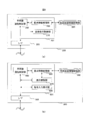
- Diagram showing the schematic configuration of the control system It is a hardware block diagram of a control server, a dump truck, and a manned vehicle, (a) shows a control server, (b) shows a dump truck, (c) shows a manned vehicle.
- Functional block diagram showing the main functions of the control server 2 is a functional block diagram showing main functions on the vehicle side
- (a) is a functional block diagram showing functions of the dump truck 20
- (b) is a functional block diagram showing functions of the manned vehicle 90.
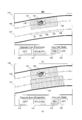
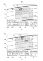
- the screen displayed on the display apparatus of the navigation apparatus with which the dozer (manned vehicle) was equipped (a) is a screen after the dozer acquires the section on the adjacent two lanes as the travel permission section, (b ) Is a diagram showing a screen in a state where the dozer has finished the work and returned to the own lane, but the direction of the vehicle body is opposite to the traveling direction. It is an example of the screen displayed on the display apparatus of the navigation apparatus with which the dozer (manned vehicle) was equipped, (a) is a state in which the operator of the manned vehicle designates two points for which the section on the opposite lane is to be manually acquired.
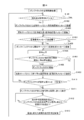
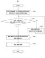
- FIG. 9 is a flowchart for explaining a procedure for allowing the other lane travel permission unit of the control server to permit a travel on the opposite lane to the manned vehicle when an operator of the manned vehicle performs an operation based on the screen of FIG. 9.
- each configuration, function, processing unit, processing unit, and the like, which will be described later, may be realized (configured) as a program executed on a computer. That is, it may be realized as software.
- a CPU executing software constitutes each unit (may be referred to as each device or each device).
- each unit is not limited to the CPU, and may be configured as an integrated circuit that implements each function.
- Each unit may be configured by a single control device, or may be configured by connecting a plurality of control devices. Also, when configured as a plurality of control devices, each control device does not need to be mounted in the same housing, each control device is mounted in another housing, whether wired or wireless, Moreover, the structure connected by communication always or when needed may be sufficient.
- Information such as programs, tables, files, etc. for realizing each configuration, function, processing unit, processing means, etc. is stored in memory, hard disk, storage device such as SSD (Solid State Drive), storage medium such as IC card, SD card, DVD, etc. Can be stored.
- SSD Solid State Drive
- storage medium such as IC card, SD card, DVD, etc. Can be stored.
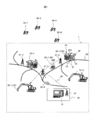
- FIG. 1 is a diagram showing a schematic configuration of a control control system.
- the control control system 1 shown in FIG. 1 is a mine for transporting loads such as earth and sand and ore loaded from excavators 10-1 and 10-2 performing excavation and loading work in a quarry such as a mine.
- manned vehicles 90-1 and 90-2 used for the movement of workers are connected to each other via a wireless communication line 40. Since a dump truck is used as the autonomous traveling vehicle, the autonomous traveling vehicle is hereinafter referred to as a dump truck.
- the control server 31 is a control control device that performs traffic control of the dump truck and the manned vehicle.
- Each of the dump trucks 20-1 and 20-2 reciprocates between the excavator 10-1 or 10-2 and the unloading ground (not shown) along the conveyance path 60 set in advance in the mine, and conveys the load. .
- radio base stations 41-1, 41-2, 41-3 are installed. Then, radio communication radio waves are transmitted and received through these radio base stations 41-1, 41-2, and 41-3.
- the excavators 10-1 and 10-2, the dump trucks 20-1 and 20-2, and the manned vehicles 90-1 and 90-2 each include at least four positioning satellites 50-1 and 50-2 of GPS (Global Positioning System). , 50-3, 50-4, and a position calculating device (not shown in FIG. 1) for acquiring the position of the host vehicle by receiving positioning radio waves. Since the configurations of the dump trucks 20-1 and 20-2 are the same, hereinafter, the dump trucks 20-1 and 20-2 are collectively referred to as the dump truck 20 without being distinguished. Also, since the excavators 10-1 and 10-2 have the same configuration, the excavators 10-1 and 10-2 are collectively referred to as the excavator 10 in the following without being distinguished. Further, since the configurations of the manned vehicles 90-1 and 90-2 are the same, the manned vehicles 90-1 and 90-2 are hereinafter collectively referred to as the manned vehicles 90 without being distinguished from each other.
- GPS Global Positioning System
- the dump truck 20 includes a frame 21 that forms a main body, a front wheel 22 and a rear wheel 23, and a loading platform 24 that can rotate in the vertical direction about a hinge pin (not shown) provided at a rear portion of the frame 21. And a pair of left and right hoist cylinders (not shown) that rotate the loading platform 24 in the vertical direction.
- the dump truck 20 is provided with an antenna 25 for connecting to the radio communication line 40 in a place with a good view, for example, in front of the upper surface of the dump truck 20.
- the dump truck 20 is equipped with a travel control device 200 for autonomous travel according to instructions from the control server 31.
- the manned vehicle 90 is a vehicle that travels according to the driving operation of the driver.
- the manned vehicle 90 is equipped with a navigation device 900 (vehicle terminal device) for a driver to perform a driving operation in accordance with an instruction from the control server 31.
- a navigation device 900 vehicle terminal device
- the control server 31 is connected to an antenna 32 for connecting to the wireless communication line 40.
- the control server 31 communicates with the dump truck 20 and the manned vehicle 90 via the antenna 32 and the radio base stations 41-1, 41-2, and 41-3.
- FIG. 2 is a hardware configuration diagram of the control server 31, the dump truck 20, and the manned vehicle 90, where (a) shows the control server, (b) shows the dump truck, and (c) shows the manned vehicle.
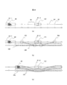
- FIG. 3 is a view showing the appearance of the dump truck 20.
- the control server 31 includes a CPU 311, a RAM (Random Access Memory) 312, a ROM (Read Only Memory) 313, an HDD (Hard Disk Drive) 314, an I / F 315, and a bus 318.
- a CPU 311, a RAM 312, a ROM 313, an HDD 314, and an I / F 315 are connected via a bus 318.
- the control server 31 further includes a display device 316 and an input device 317, which are connected to the I / F 315.
- the CPU 311 is a calculation unit and controls the operation of the entire control server 31.
- the RAM 312 is a volatile storage medium that can read and write information at high speed, and is used as a work area when the CPU 311 processes information.
- the ROM 313 is a read-only nonvolatile storage medium and stores an autonomous traveling control program.
- the HDD 314 is a non-volatile storage medium capable of reading and writing information, and stores an OS (Operating System), various control programs, application programs, and the like.
- OS Operating System
- the display device 316 is a user interface for the user to check the traveling state of the dump truck in the mine, and is configured by, for example, an LCD (Liquid Crystal Display).
- the input device 317 is a user interface for a user to input information to the control server 31, and is configured using a touch panel (not shown) stacked on a mouse, a keyboard, or an LCD, for example.
- the server side communication device 340 for connecting to the wireless communication line 40 is connected to the I / F 315 of the control server 31.
- the dump truck 20 has a traveling control device 200 that performs control processing for autonomous traveling, as shown in FIG. 2B, and for driving the dump truck 20 according to a control instruction from the traveling control device 200.
- a vehicle-side communication device 240 for connecting to the vehicle.
- the traveling drive device 210 includes a braking device 211 for braking the dump truck 20, a steering motor 212 for changing the steering angle of the dump truck 20, and a traveling motor 213 for causing the dump truck 20 to travel.
- the position calculation device 220 is a device for identifying the own position.
- the position calculation device 220 receives the positioning radio waves from the positioning satellites 50-1, 50-2, 50-3, 50-4 and calculates the position of the own vehicle. Therefore, the dump truck 20 includes a GPS antenna 221 (see FIG. 3).
- the position calculation device 220 does not need to be a GPS.
- the position calculation device 220 may be based on an inertial measurement device (IMU: Internal Measurement Unit) or a system that specifies a position using radio waves from a base station installed on the ground. Good.
- the dump truck 20 includes an antenna for the system, a gyro sensor, and a sensor for detecting the number of rotations of the wheel instead of the antenna 221 for GPS.
- the in-vehicle sensor 230 is for recognizing and estimating the speed of the dump truck 20 and the surrounding environment, and corresponds to, for example, a device that constitutes one element of a road shoulder detection device or detects a front obstacle.
- the road shoulder detection device the laser radar sensors 231L and 231R (see FIG. 3) are provided in this embodiment, but the present invention is not limited to this, and a road shoulder may be detected by image processing using a camera.
- the laser radar sensors 231L and 231R replace a camera installed so as to look down at the side of the vehicle body.
- a millimeter wave radar sensor 232 is provided as a forward obstacle detection device, and an obstacle ahead of the dump truck 20 in the traveling direction is detected using this output.
- a plurality of cameras directed forward may be provided. In this case, the plurality of cameras may be installed at positions above the position shown in FIG. 3 so as to look down.
- the detection result of the in-vehicle sensor 230 is output to the traveling control device 200, and is used for monitoring the traveling position and accelerating / decelerating so as not to leave the traveling path in a normal state, and used for a braking operation necessary for emergency avoidance behavior in an emergency.
- the travel control device 200 includes a CPU 201, a RAM 202, a ROM 203, an HDD 204, an I / F 205, and a bus 208.
- a CPU 201, a RAM 202, a ROM 203, an HDD 204, and an I / F 205 are connected via a bus 208.
- a travel drive device 210, a position calculation device 220, an in-vehicle sensor 230, and a vehicle side communication device 240 are connected to the I / 205.
- the manned vehicle 90 includes a navigation device 900 for transmitting instructions from the control server 31 to an operator who operates the vehicle, and the vehicle position of the manned vehicle 90.
- a position calculation device 920 for calculating and a vehicle side communication device 940 for connecting to the wireless communication line 40 are provided.
- the navigation device 900 includes a CPU 901, a RAM 902, a ROM 903, an HDD 904, an I / F 905, a bus 908, a display device 906 for displaying information acquired by the navigation device 900 to the operator, and the operator inputs an operation command to the navigation device 900.
- An input device 907 serving as a user interface.
- the CPU 901, RAM 902, ROM 903, HDD 904, and I / F 905 are connected via a bus 908, and the display device 906 and the input device 907 are connected to the I / F 905. Further, a position calculation device 920 and a vehicle side communication device 940 are connected to the I / F 905.
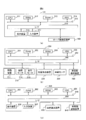
- FIG. 4 is a functional block diagram showing the main functions of the control server.
- FIG. 5 is a functional block diagram showing main functions on the vehicle side, where (a) is a functional block diagram showing functions of the dump truck 20, and (b) is a functional block diagram showing functions of the manned vehicle 90.
- the control server 31 includes a dump truck 20, a server side communication control unit (corresponding to a control side communication control unit) 310 that performs control for performing wireless communication with the manned vehicle 90, A control unit 320 that determines a destination and a travel route to the destination and controls traffic so that the dump trucks do not interfere with each other or between the dump truck and the manned vehicle, and the transport that the dump truck 20 and the manned vehicle 90 travel.
- a control map information storage unit 314a that stores road map information
- a section information storage unit 314b that stores position information of the set travel permission sections and other lane travel permission sections described later are provided.
- the conveyance path is a road connecting the starting point and the ending point of the dump truck 20 such as a loading place, a dumping place, a parking lot not shown, and a plurality of lanes are set on the road.
- the adjacent lane becomes the opposite lane.
- the adjacent lane may be an overtaking lane.
- the server-side communication control unit 310 is connected to the server-side communication device 340 via the I / F 315 and performs control for performing actual wireless communication with the dump truck 20 and the manned vehicle 90.
- the control control unit 320 includes a vehicle allocation management unit 321, a travel permission section setting unit 322, and an other lane travel permission unit 323.
- the vehicle allocation management unit 321 sets the destination of the dump truck 20 and refers to the map information stored in the control map information storage unit 314a to determine the travel route from the current position to the destination.
- the vehicle allocation management unit 321 sets the purpose of the loading area entrance including the loading position.
- the vehicle allocation management unit 321 sets a traveling lane from the parking lot to the entrance on the loading.
- the vehicle allocation management unit 321 may dynamically generate a travel path (dynamic path) as the loading position moves.
- the vehicle allocation management unit 321 sets one of the earthmoving sites 62 and 63 as a destination depending on the content of the load, and sets a dynamic path up to that point. Generate.
- an operator boarding the manned vehicle 90 inputs a destination using the navigation device 900, and the vehicle side communication device 240 and the server side communication device 340 are used.
- the input destination may be transmitted to the control server 31, and the route from the current position of the manned vehicle 90 to the input destination may be set as a travel lane by the vehicle allocation management unit 321 of the control server 31.
- the travel permission section setting unit 322 sets a part of the travel lane of the manned vehicle 90 as a first travel permission section in which travel permission is given only to the manned vehicle 90. Further, a part of the travel lane of the dump truck 20 is set as a second travel permission section in which travel permission is given only to the dump truck 20.
- the travel permission section setting unit 322 updates the position information of the first and second travel permission sections by overwriting the section information stored in the section information storage unit 314b.
- the section information includes the node ID of the front boundary point that is the frontmost node of the travel permitted section and the node ID of the rear boundary point that is the last node.
- section request message information requesting setting of a new travel permission section from the dump truck 20 or the manned vehicle 90
- section response message information indicating the travel permission section
- the travel permission section setting unit 322 refers to the section information when setting the first travel permission section and the second travel permission section. And the 1st run permission section set up to the vehicles which transmitted the section demand message to the 1st run permission section and the 2nd run permission section which are set up for other vehicles, and the other lane run permission section mentioned below Or it sets so that the 2nd run permission section may not overlap. Thereby, a some vehicle does not approach into the same 1st travel permission area and the 2nd travel permission section, and interference between vehicles can be avoided.
- the other lane travel permission unit 323 permits the other lane travel permission in which only the manned vehicle 90 is permitted to travel in a section including at least a part of the section parallel to the first travel permission section in the lane adjacent to the travel lane of the manned vehicle 90.
- the other lane travel permission section may be a section including a section parallel to the first travel permission section in the adjacent lane (a section longer than the first travel permission section in the front-rear direction).
- the other lane travel permission unit 323 is set for the other vehicle traveling in the lane adjacent to the travel lane of the manned vehicle to be set in the other lane travel permission section when the other lane travel permission section is set. If the other vehicle travel permission section does not overlap the first travel permission section and the second travel permission section, in other words, if the other vehicle on the adjacent lane is stopped, the first travel permission set for the other vehicle.
- the other vehicle travel permission section is set so as to overlap the section or the second travel permission section. Accordingly, the manned vehicle can pass after the vehicle in the adjacent lane stops, or can be overtaken (including a case where the manned vehicle travels in the lane of the manned vehicle and passes the vehicle in the adjacent lane).
- the other lane travel permission unit 323 sets a new first travel permission section for the manned vehicle 90 in the automatic acquisition mode of the other lane travel permission section (details will be described later).
- the other lane travel permission unit 323 follows and sets the new other lane travel permission section in a section parallel to the new first travel permission section.
- the display control unit 340 displays on the screen of the display device 316 the positions of the dump truck 20 and the manned vehicle 90 that travel on the conveyance path 60, the self-setting states of the first travel permission section, the second travel permission section, and the other lane travel permission section. Control the display.
- the control map information storage unit 314a stores the map information of the conveyance path 60.
- the section information storage unit 314b stores section information indicating the positions of the first travel permission section, the second travel permission section, and the other lane travel permission section being set.
- the travel control device 200 mounted on the dump truck 20 includes a vehicle-side communication control unit (corresponding to a terminal-side communication control unit) 250, a request information processing unit 260, an autonomous travel control unit 270, And a vehicle map information storage unit 280.
- the vehicle-side communication control unit 250 controls wireless communication performed with the control server 31.
- the vehicle-side communication control unit 250 transmits a section request message and receives a section response message or a non-permission response message.
- the request information processing unit 260 is a point where the dump truck 20 transmits a section request message based on the map information stored in the vehicle map information storage unit 280 and the own vehicle position calculated by the position calculation device 220 (see FIG. 2). When the request point is reached, a section request message is generated and a section request message is transmitted to the control server 31 via the vehicle-side communication control unit 250.
- the autonomous travel control unit 270 acquires the host vehicle position from the position calculation device 220, refers to the map information in the vehicle map information storage unit 280, and causes the host vehicle to travel according to the travel permission section included in the section response message. Control is performed on the traveling drive device 210 (see FIG. 2). In addition, the autonomous traveling control unit 270 determines the presence or absence of a front obstacle based on the detection result of the in-vehicle sensor 230, determines whether or not there is an interference with the obstacle and a collision avoidance operation, and if necessary, the braking operation is performed. Control for. Further, the autonomous traveling control unit 270 performs drive control on the braking device 211 in accordance with an instruction from the control server 31, and performs a deceleration operation, a normal stop operation, or an emergency stop operation.
- the navigation device 900 mounted on the manned vehicle 90 includes a vehicle side communication control unit 950, a request information processing unit 960, a display control unit 970, a command input receiving unit 990, and a vehicle map information storage unit. 980.
- a vehicle side communication control part 950 the request
- the command input receiving unit 990 is configured such that an operator boarding the manned vehicle 90 operates the input device 907 to specify a destination of the manned vehicle, or to another lane including a lane adjacent to the traveling lane of the manned vehicle 90. An operation for making a setting request for another lane travel permission section is accepted. When the operator wants to work on another lane, the operator performs an operation for acquiring the other lane travel permission section from the input device 907, and the command input receiving unit 990 receives the input operation and makes a setting request for the other lane. Message (hereinafter referred to as “other lane section request message”).
- command input receiving unit 990 receives an operation in which the operator makes a request to cancel the other lane travel permission section.
- the display control unit 970 uses the information in the vehicle map information storage unit 980 to display an image of the conveyance path on which the manned vehicle 90 travels on the display device 906 and to superimpose it on the navigation device 900 from the control server 31.
- the position information of the first travel permitted section and the other lane travel permitted section and the current position of the host vehicle calculated by the position calculating device 920 are displayed on the display device 906.
- An operator who controls the manned vehicle 90 looks at the first travel permitted section of the host vehicle displayed on the display device 906 and the current position of the host vehicle, and travels the vehicle so as not to protrude from the first travel permitted section.
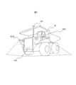
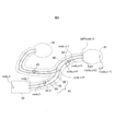
- FIG. 6 is a diagram illustrating a configuration example of an open pit mine site where a dump truck and a manned vehicle travel.
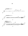
- FIG. 7 is a diagram showing a communication operation between the dump truck and the control server at the start of autonomous driving, where (a) shows a state in which a destination request message is transmitted from the dump truck, and (b) The response state from a control server is shown, (c) shows the request
- FIG. 8 is a diagram showing details of setting of the travel permission section, where (a) shows a state in which a request message for the travel permission section is transmitted from the dump truck and manned vehicle, and (b) is a response from the control server. A message is shown, and (c) shows a request and response state of the travel permission section.
- FIG. 6 indicates an excavation site using a mining machine such as the excavator 10 and a loading place 61 on which the mining machine loads the dump truck 20.
- a loading position corresponding to LP in FIG. 6
- the topsoil and ore dug by the excavator 10 are loaded onto the dump truck 20 at the loading place 61.
- Reference numeral 62 denotes an earth release site that unfolds the topsoil, and the topsoil and the like carried from the loading place 61 are unearthed at this place and are developed in layers or radially.
- Reference numeral 63 denotes an earthmoving site in which a crusher for crushing ore is installed, and the crushed ore is transported to a freight car unloading site or a processing facility by a belt conveyor or the like.
- QP in FIG. 6 is an entrance to the loading place 61, and the dump truck 20 stops and waits until the excavator 10 permits the dump truck to enter the loading position (CALL). Indicates the standby position.
- EXIT in FIG. 6 is an exit from which the dump truck 20 exits from the loading place 61.
- the dump truck 20 loads topsoil and ore at the loading field 61, travels on the conveyance path 60, and conveys them to the earthing fields 62 and 63.
- a travel path (lane) 64 is set in the transport path 60, and the dump truck 20 travels along the travel path 64.
- the travel path 64 is given as a coordinate value set on the map.
- the dump truck 20 autonomously travels along the travel path 64 by controlling acceleration / deceleration and steering while comparing the self-position specified by the GPS or other position calculation device with the coordinate value of the travel path 64.
- a node 65 indicating a boundary between sections of the travel path and a link 66 connecting the adjacent nodes 65 are provided.
- Information on the actual traveling path 64, the node 65, and the link 66 is stored as the same map information in the control map information storage unit 314a and the vehicle map information storage units 280 and 980.
- the map information also stores the traveling direction of the travel path 64 (lane).
- the control server 31 assigns / cancels the travel permission for each travel section including the two adjacent nodes 65 and one link 66 by the control control unit 320, and uses the information as section information for the dump truck 20 and the manned vehicle 90. Notify Thereby, traveling is controlled so as to avoid a collision between the dump truck and the manned vehicle.
- the travel path 64 is provided with a speed limit for each section, and the dump truck 20 travels at an appropriate speed while referring to the vehicle map information storage units 280 and 980 speed limit information.
- the dump truck 20 In a state where the topsoil and ore have been completely loaded in the loading place 61, or in a state where the earthing in the earthing places 62 and 63 has been completed, the dump truck 20 returns to the control server 31 as shown in FIG. To send a message requesting the destination (destination request message).
- the request information processing unit 260 determines the current own vehicle position and the vehicle status (stopped) and transmits the vehicle via the vehicle-side communication control unit 250.
- the destination request message is received by the server-side communication control unit 310 on the control server 31 and transmitted to the control control unit 320.
- the vehicle allocation management unit 321 in the control control unit 320 refers to the map information in the control map information storage unit 314a, considers the situation of other dump trucks 20 and the like, and determines the destination of the dump truck that requested the destination. A route to the destination is determined, and the server side communication control unit 310 is instructed to transmit a destination response message indicating the destination 80 and the route 81 to the destination to the dump truck.
- the server-side communication control unit 310 transmits a destination response message to the dump truck 20 via the wireless communication line 40 (see FIG. 7B).
- the request information processing unit 260 on the dump truck 20 transmits a message (section request message) for requesting setting of the second travel permitted section to the control server 31.
- the server-side communication control unit 310 transmits a section request message to the control control unit 320.
- the travel permission section setting unit 322 of the control control unit 320 sets the second travel permission section 82 based on the process described below, and sends a message (section response message) indicating the set second travel permission section to the dump truck 20. (FIG. 7 (c)).
- the section response message includes information for uniquely identifying the foremost node of the second travel permitted section (node ID), information for uniquely identifying the last node ID, and a link included in the second travel permitted section (link). ID).
- the dump truck 20 can start traveling only after obtaining the travel permission section.
- the second travel-permitted section received from the control server 31 is recorded in the vehicle map information storage unit 280 on the vehicle, and how far the vehicle can travel by referring to this is autonomously traveled. to decide.
- the second travel permitted section includes unique information (link ID) that uniquely indicates the link 65 included in the travel permitted section, including the foremost node ID, the last node ID included in the section response message, and the link ID located therebetween. ).
- dump trucks 20-1 and 20-2 are traveling vehicles, and reference numerals 81-1 and 81-2 are travel permission sections permitted for the respective vehicles.
- the dump trucks 20-1 and 20-2 are both traveling in the direction indicated by the arrow A.
- Reference numeral 83 denotes a travel permission remaining distance indicating a distance along the travel lane from the current position of the dump truck 20-1 to the foremost end (terminal) of the travel permission section 81-1.
- Reference numeral 84 denotes a travel permission request start distance indicating a distance from the foremost end (termination) to a point at which the dump truck 20-1 starts transmission of a section request message.
- the travel permission request start distance 84 is longer than the distance at which the dump truck can be stopped, and is, for example, a predetermined offset distance added to the stopable distance.
- the distance L at which the dump truck can be stopped is, for example, m, including the vehicle load, v, the current speed of the vehicle, f, the braking force of the vehicle, and the offset coefficient c defined in accordance with the safety factor. Then, it calculates
- the offset coefficient c is a value of 1 or more, and is set in consideration of, for example, the time required for wireless communication or the degree of occurrence of a wireless communication failure.
- the speed of the vehicle may be a value obtained by measuring the current speed of the vehicle from the number of rotations of the wheel, etc., and a speed limit (maximum allowable speed) defined in the map information for the current travel position of the vehicle. May be used.
- the dump truck 20-1 when the remaining travel permitted distance 83 of the dump truck 20-1 becomes equal to or less than the travel permission request start distance 84, the dump truck 20-1 sends a section request message to the control server 31. Send.
- This section request message also includes the vehicle position information of the dump truck 20-1.
- the control server 31 When the control server 31 receives the section request message from the dump truck 20-1, the control server 31 specifies the traveling section where the dump truck 20-1 exists using the sent vehicle position information. Then, along the traveling direction of the dump truck 20-1, the distance becomes equal to or longer than the shortest distance (travel permission grant length) given as a predetermined second travel permission section from the end of the section where the dump truck 20-1 exists. Grant travel permission to the section. However, if there is a section for which permission is given to another vehicle, the travel permission is given up to that point.
- the section where the dump truck 20-1 exists is 85, and the sections with the travel permission grant length of 95 or more from the end are 86, 87, 88, 89.
- the running permission for the dump truck 20-2 has already been given to the sections 88 and 89, the running permission for 86 and 87 is given.
- the section 87 is given as a new second travel permission section.
- the section for which travel permission has been granted is released when the distance from the vehicle position to the end of the section is equal to or greater than the travel permission cancellation distance after the vehicle passes through the section.
- the section 88 in which the travel permission is given to the dump truck 20-1 is traveled when the distance 91 between the vehicle 20-2 and the end of the section becomes the travel permission release distance 92 or more. The permission is released, and it becomes possible to assign a travel permission to the subsequent dump truck 20-1.
- the first travel permitted section is set with the same logic as the second travel permitted section.
- the travel permission section setting unit 322 of the control server 31 responds to the section request message from each of the manned vehicle and the unmanned vehicle, and the first / second travel permission for the vehicle that has transmitted the section request message on the travel lane of the vehicle. Set the interval.
- the first / second travel permission section is a section in which only the set vehicle is permitted to travel, and the entry of other vehicles is prohibited, so that the other vehicle functions as a closed section. Therefore, as long as the autonomous traveling vehicle and the manned vehicle are traveling according to the first / second traveling permission section set for the own vehicle, the interference between the two vehicles does not occur.
- a manned vehicle in order to avoid a situation in which a manned vehicle passes or is overtaken by a traveling autonomous vehicle, a manned vehicle is also manned in the adjacent lane following the travel permission section set for the manned vehicle. Set the travel permission section for the vehicle, stop the autonomous vehicle when the manned vehicle passes the autonomous vehicle, and work when the manned vehicle works in another lane provided in parallel with the own lane. Avoid interference between manned vehicles and autonomous vehicles.
- the navigation device 900 is mounted on the manned vehicle 90 in the present embodiment, and the travel permission section setting unit is installed in the control server 31. 322 and another lane travel permission unit 323 are provided.
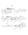
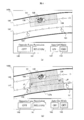
- FIG. 9 is an example of a screen displayed on the display device 906 of the navigation device 900 provided in the dozer (manned vehicle).
- FIG. 9A shows a state before the manned vehicle acquires a section on the oncoming lane as a travel permission section.
- FIG. 10 shows an example of a screen displayed on the display device 906 of the navigation device 900 provided in the dozer (manned vehicle).
- FIG. 10A shows after the dozer acquires a section on two adjacent lanes as a travel permission section.
- (B) is a diagram showing a screen in a state in which the dozer has finished work and returned to its own lane, but the direction of the vehicle body is opposite to the traveling direction.
- FIG. 11 shows an example of a screen displayed on the display device 906 of the navigation device 900 provided in the dozer (manned vehicle).
- FIG. 10 shows an example of a screen displayed on the display device 906 of the navigation device 900 provided in the dozer (manned vehicle).
- FIG. 11A shows two points that the operator of the manned vehicle wants to manually acquire a section on the oncoming lane.
- (B) is a figure which shows the screen after searching the boundary point of an acquisition area, and the manned vehicle acquired the area on an oncoming lane as a driving
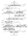
- FIG. 12 shows a procedure in which another lane travel permission unit 323 of the control server 31 permits a travel on the opposite lane to the manned vehicle when an operator of the manned vehicle performs an operation based on the screen of FIG. It is a flowchart explaining these.
- FIG. 13 is a flowchart for explaining an operation procedure when the manned vehicle cancels the travel permission section in the oncoming lane.
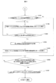
- a screen 145 is a screen of a display device 906 mounted on a dozer traveling on a one-lane conveyance path
- reference numeral 130 is a dozer
- reference numeral 131 is a travel permission section set for the dozer 130.
- Reference numeral 146 denotes a traveling lane (own lane) in which the dozer 130 is traveling
- 147 denotes an opposite lane.
- an oncoming lane section acquisition button 140, an oncoming lane section release button 141, an automatic acquisition mode ON button 142, and an automatic acquisition mode OFF button 143 are provided below the screen. These buttons may be displayed on the screen and operated with a touch panel, or may be provided as physical buttons separately from the screen display.
- a screen 145a is displayed on a display device 906 mounted on a dozer that performs work on a total of three lanes, that is, an own lane (uphill lane), a traveling lane that is parallel to the own lane, and an opposite lane.
- a screen 130 is a dozer, and 131 is a travel permission section set in the dozer 130.
- Reference numeral 146 denotes the own lane in which the dozer is running
- 146a denotes a running lane (parallel running lane)
- 147 denotes an oncoming lane.
- another lane section acquisition button 140a In the lower part of the screen, another lane section acquisition button 140a, another lane section release button 141a, automatic acquisition mode ON button 142, automatic acquisition mode OFF button 143, and a lane number input button for inputting the number of other lanes for acquiring the section 144.
- the other lane section acquisition button 140a and the other lane section release button 141a are buttons that are operated when inputting a setting request for another lane travel permission section similar to the oncoming lane section acquisition button 140 and the oncoming lane section release button 141 in FIG.
- the lane other than the oncoming lane is included in the other lanes, so the names are changed.
- the lane number input button 144 is used for acquiring the number of other lanes provided on the right side (R) in the traveling direction of the own lane, and acquiring the other lanes provided on the left side (L) in the traveling direction of the own lane.
- a button for entering each of the numbers In FIG. 10A, since the dozer 130 is traveling in the lane 146, the right lane number input button 144 designates the right two lanes and the left zero lane, and acquires the other lane travel permission section 137a on the right two lanes. However, when the dozer 130 is traveling in the lane 146 and acquires sections for all three lanes, the right lane and the left lane are designated by the lane number input button 144. Further, when a section is acquired only by the lane 146 a adjacent to the dozer 130 on the own lane 146, the right lane input button 144 specifies the right lane 1 and the left lane 0 lane.
- the dozer 130a When the operator operates the other lane section release button 141a in FIG. 10B, the dozer 130a is in a position across the two travel permission sections 131 and 137a, that is, the position where the dozer 130a is not included in one travel permission section.
- the command input receiving unit Even if 990 detects an operation on the other lane section release button 141a, the other lane section release button 141a is not changed to active without generating a release request message.
- a screen 145b is a screen of the display device 906 mounted on the dozer 130 that travels on the one-lane conveyance path.
- the command input reception unit 990 extracts two nodes adjacent to the point 150 from the map information, and either the extracted points or the front / rear boundary points of the first travel permission section 131. Distances d1 and d2 with the closer one (the rear boundary point in FIG. 11) are calculated. Then, the node having the shorter distance, that is, the node at the distance d2 from the rear boundary point is selected as one boundary point of the other lane travel permission section.
- the point 151 two nodes adjacent to the point 151 are extracted, and the distance between each extracted point and the front / rear boundary point of the travel-permitted section, whichever is closer (the front boundary point in FIG. 11). d3 and d4 are calculated. Then, the node having the shorter distance, that is, the node at the distance d3 from the front boundary point is selected as one boundary point of the other lane travel permission section. Thereby, the section 137b shown in FIG. 11B is input as the acquisition request section of the other lane travel permission section.
- the command input receiving unit 990 has an algorithm for searching for the boundary point of the acquisition request section, so that when the operator manually inputs the acquisition request section, the node is input even if an input operation is performed at a position off the other lane. Since the interval between them can be set as the acquisition request interval, it is not necessary for the operator to select the node accurately, and the convenience of operation is improved.
- the above algorithm is only an example of an acquisition request section by manual operation, and other algorithms will be mentioned in the flowchart described later.
- the oncoming lane section acquisition button 140 (S1201).
- the other lane section acquisition button 140a and the lane number input button 144 are pressed instead of the oncoming lane section acquisition button 140.
- the automatic acquisition mode ON button 142 is pressed in advance to confirm that the button is active.
- the automatic acquisition mode OFF button 143 is pressed to confirm that the button is active.
- the command input reception unit 990 refers to the vehicle map information storage unit 980, and
- the ID of the section on the opposite lane or the other lane adjacent to the travel permission section of the host vehicle currently set on the line is acquired (S1203).
- Adjacent sections may be associated with each other in advance and held in the vehicle map information storage unit 980, or may be configured to perform geometric calculation and perform sequential calculation when necessary.
- the section on the other lane from which the ID is acquired at this time is, for example, a link 132 constituted by two nodes on the opposite lane closest to the end points 138 and 139 of the travel permitted section on the own lane in FIG. , 136, and a series of sections 132, 133, 134, 135, 136.
- the command input receiving unit 990 sends a section request message for requesting the request information processing unit 960 to set the next (new) travel permission section.
- a message for requesting setting of another lane section (referred to as “other lane section request message”) is also transmitted at the time of transmission.
- a flag area indicating whether or not another lane section request message is necessary is provided in a predetermined area of a memory mounted on the navigation device 900, and “1” is set in the flag area in the automatic acquisition mode.
- the request information processing unit 960 refers to the flag area before transmitting the section request message, and if “1” is set, also transmits the other lane section request message together with the section request message.
- the above flag area is secured in the memory mounted on the control server 31.
- the command input reception unit 990 transmits another lane section request message to the control server 31 and sets “1” in the flag area of the control server 31.
- the other lane travel permission unit 323. May be configured to set the travel permission section in a section of another lane adjacent to the first travel permission section newly set for the manned vehicle. In that case, the other lane travel permission unit 323 also cancels the other lane travel permission section set following the first travel permission section in accordance with the cancellation of the first travel permission section.
- the operator designates a section on the other lane (S1204).
- the section designation method is, for example, that the operator designates any two points on the screen with other lanes sandwiched by touch or the like (see FIG. 11), and generates a rectangular region having the two points as diagonal points.
- the section on the other lane included in the inside may be extracted as the acquisition request section. At this time, not only the section on the other lane but also the section on the own lane may be specified together. Alternatively, any two sections on other lanes may be designated by touch or the like, and a series of sections including them may be designated.
- the command input receiving unit 990 acquires the ID of the section designated in this way with reference to the vehicle map information storage unit 980 (S1205).
- the command input receiving unit 990 of the manned vehicle When the section ID on the other lane is acquired by the above method, the command input receiving unit 990 of the manned vehicle generates an other lane section request message including the acquired section ID, and the control server 31 via the vehicle side communication control unit 950. (S1206).
- the other lane travel permission unit 323 receives the other lane section request message including the section ID via the server side communication control unit 310.
- the other lane travel permission unit 323 refers to the section information in the section information storage unit 314b and confirms whether the section is permitted for other vehicles (S1207).
- the section is set as the other lane travel permission section of the manned vehicle and written in the section information of the section information storage unit 314b (S1208), and the other lane travel permission set for the manned vehicle through the server side communication control unit 310 is set.
- the section is transmitted (S1209).
- control server 31 transmits a message indicating that another lane travel permission section acquisition failure has occurred to the manned vehicle (S1210).
- the manned vehicle display control unit 970 receives the message transmitted from the control server 31 via the vehicle-side communication control unit 950, and displays the result on the in-vehicle terminal (S1211).
- the areas 137 (see FIG. 9), 137a (see FIG. 10), and 137b (see FIG. 11) designated on the other lane are colored as the travel permission section of the manned vehicle and displayed on the screen.
- FIG. 13 is a flowchart showing an operation procedure for canceling a travel permission section on another lane.
- the operator of the manned vehicle presses the other lane section release buttons 141 and 141a of the navigation device 900 (S1301).
- the command input reception unit 990 receives the manned vehicle body in the first travel permission section and the direction of the vehicle body matches the traveling direction of the first travel permission section, or the manned vehicle body permits the other lane travel permission.
- the vehicle is included in the section and the direction of the vehicle body coincides with the traveling direction of the other lane travel permission section (S1302 / Yes)
- a release request is generated and transmitted from the vehicle side communication control unit 950 to the control server 31 (S1303).
- the other lane travel permission section 323 of the control server 31 receives the release request message, cancels the other lane travel permission section, and deletes the data of the other lane travel permission section released from the section information in the section information storage section 314b (S1304).
- the display control unit 970 of the navigation device 900 updates the screen, displays the other lane travel permission section for the host vehicle, and displays the first travel permission section that is currently traveling. An image is displayed (S1305).
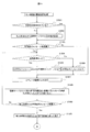
- FIG. 14 is a flowchart showing a flow of control control processing for the dump truck. In the following, description will be given along the order of steps in FIG.
- the request information processing unit 260 of the travel control device 200 sends a destination request message (current position) to the control server 31 via the wireless communication line 40. Information is included) (S1402).
- the dispatch management unit 321 of the control server 31 sets the destination by referring to the current position information of the dump truck 20 and the map information of the control map information storage unit 314a, and sends a destination response message indicating the result to the dump truck 20. (S1403).
- the destination of the dump truck 20 is set (S1401 / Yes) and after sending the destination response message, the process proceeds to step S1404.
- the section information message is transmitted from the request information processing section 260 (S1405).
- step S1406 is performed.
- the dump truck 20 is substantially stopped (not started). In this case, “No” is selected in the next step S1407, the first travel permitted section is set in S1409, and autonomous travel is started by the next loop.
- the dump truck 20 waits for the reception of the section response message from the control server 31 while continuing to travel in accordance with the currently permitted travel section after transmitting the section request message.
- the autonomous travel control unit 270 compares the own vehicle position from the position calculation device 220 with the vehicle map information storage unit 280 and the currently granted second travel permitted section, and the travel permitted remaining distance is equal to or less than the stop start distance. In some cases (S1407 / Yes), a braking instruction is given to the braking device 211 of the travel drive device 210 so as to stop within the second travel permission section, and the dump truck 20 starts decelerating (S1408). When the remaining travel-permitted distance is longer than the stop start distance (S1407 / No), the autonomous travel is continued without braking for stopping.
- the travel permission section setting unit 322 sets a new second travel permission section based on the own vehicle position of the dump truck 20 and the map information stored in the control map information storage unit 314a. Then, the section response message indicating the contents is transmitted to the dump truck 20 (S1409).
- the dump truck 20 When the dump truck 20 receives the section response message (S1410 / Yes), the dump truck 20 starts to travel according to the new travel permission section indicated in the section response message (S1411). When the dump truck 20 does not receive the section response message, the process returns to step S1405 (S1410 / No).
- the case where the section response message is not received includes, for example, a case where the section request message does not reach the control server 31 due to a communication error, and the section response message does not reach the dump truck 20.
- the travel permission section setting unit 322 cancels the setting of the travel permission section. (S1413).
- the travel permitted section setting unit 322 deletes information indicating the travel permitted section that has been released from the section information. Thereafter, the process returns to step S1401.
- the travel permission section setting unit 322 does not cancel until the travel permission release distance is exceeded. The dump truck travels (S1412).
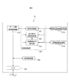
- FIG. 15 is a flowchart showing the first half of the control control process for the manned vehicle.
- FIG. 16 is a flowchart showing the latter half of the control control process for manned vehicles.
- the difference regarding the manned vehicle from the dump truck is that the destination is determined not by the control server 31 but by the operator, and the traveling control is executed by the operator's operation.
- description will be given along the order of steps in FIGS. 15 and 16. Note that a description of the same operation contents as those in FIG. 14 is omitted.
- the operator designates the destination with the input device 907 and transmits it to the control server 31 (S1502).
- the destination is set (S1501 / Yes) and when the destination is transmitted to the control server 31, the process proceeds to step S1503.
- the section information message 960 is transmitted from the request information processing unit 960 and the request information Another lane section request message is also transmitted from the processing unit 960 or the command input receiving unit 990 (S1505).
- the navigation device 900 may transmit the other lane segment request message together with the segment request message each time, or may transmit only once before the cancellation request message is transmitted.
- the display device 906 may display the travel permission section and the vehicle position of the host vehicle superimposed on the mine map information.
- the travel permission section setting unit 322 sets the travel permission section based on the host vehicle position of the manned vehicle and the map information stored in the control map information storage unit 314a. If necessary, the other lane travel permission unit 323 sets other lane travel permission sections and transmits a section response message indicating the contents thereof to the manned vehicle (S1508).
- the manned vehicle When the manned vehicle receives the section response message (S1509 / Yes), the manned vehicle travels under the control of the operator according to the new first travel permission section indicated in the section response message (S1510). If the other lane travel permission section is set, the manned vehicle is allowed to protrude into the other lane travel permission section. When the manned vehicle does not receive the section response message, the process returns to step S1504 (S1509 / No).
- the navigation device 900 transmits the other lane section request message from the manual acquisition mode (S1601 / Yes)
- the travel permission section acquisition processing (steps S1204 to S1211) in the other lane in the manual mode is executed (S1602). .
- the other lane travel permission section release process (see steps S1301 to S1305) is executed, and the travel permission section on the other lane is released (S1605). Thereafter, the manned vehicle travels along the travel permitted section of the host vehicle.
- the travel permission section setting unit 322 cancels the setting of the travel permission section on the own lane (S1607).
- the travel permitted section setting unit 322 deletes information indicating the travel permitted section that has been released from the section information. Thereafter, the process returns to step S1501.
- the travel permission section setting unit 322 does not cancel until the travel permission cancellation distance is equal to or greater than the manned vehicle. The vehicle runs.
- the above is the operation when the manned vehicle acquires the section on the other lane as the travel permission section of the own vehicle.
- a manned vehicle wants to work on another lane, it can move after acquiring the travel permission section of the own vehicle on the other lane beforehand, so let's overtake the manned vehicle Even if there is a vehicle or an oncoming vehicle, the vehicle stops before the travel permission section set for the manned vehicle, and interference with the manned vehicle can be prevented.
- the other lane travel permission unit assigns the other lane travel permission section to the parallel section of the other lane adjacent to the first travel permission section of the manned vehicle.
- the second travel permission section superimposed on the permission section is not given. Therefore, since the second travel permission section is given to the dump truck only before the travel permission section superimposed on the other lane travel permission section, the dump truck stops when the front boundary point is reached.
- the manned vehicle passes by with the dump truck stopped.
- the other lane travel permission section is granted for the dozer to work, the dump truck stops before that and does not enter the other lane travel permission section given to the dosa. Interference between the dump truck and the dosa is avoided.
- the example in which the section on the other lane is automatically selected when the other lane section acquisition button 140 is pressed when the automatic acquisition mode ON button 142 is active is shown.
- the ON button 142 is enabled and a manned vehicle travels on the own lane with a section on another lane already permitted to travel, along with the section on the own lane according to the normal travel permission section control method Sections on other lanes may be automatically updated. Specifically, based on the travel permitted section on the own lane and the position of the host vehicle, the manned vehicle sends a section request message to the control server as necessary, and the control server sets a new travel permitted section to the manned vehicle.
- the section on the opposite lane corresponding to the section may also be set as the travel permission section of the manned vehicle .
- the travel permission section for the opposite lane may be canceled based on the cancellation of the travel permission section for the own lane.
- the second embodiment is an embodiment in which a navigation vehicle 900 is used to acquire a travel permitted section on another lane and then overtake the preceding vehicle on the own lane by a manned vehicle.
- FIG. 17 is a functional block diagram showing main functions of the control server according to the second embodiment.
- the difference from the control server 31 of the first embodiment is that an overtaking target vehicle detection unit 324 and an overtaking route generation unit 325 are provided in addition to the configuration of the control server of the first embodiment.
- the overtaking target vehicle detection unit 324 is in the state of the travel permitted section managed by the travel permitted section setting unit 322, for example, the elapsed time since the travel permitted section is set, or the dump truck received via the server side communication control unit or The overtaking target vehicle that the dump truck should overtake is detected from the speed information of the manned vehicle.
- the overtaking route generation unit 325 generates an overtaking route for the overtaking vehicle to overtake the overtaking target vehicle ahead.
- FIG. 18 is a schematic diagram illustrating an overtaking route and a travel permitted section in the overtaking operation
- (a) is a diagram illustrating a positional relationship between the overtaking vehicle and the overtaking target vehicle and the travel permitted section of each vehicle before the overtaking operation is started.
- (B) is a figure explaining the outline
- (c) is a figure explaining the outline
- FIG. 19 is a flowchart for explaining the outline of the overtaking operation.
- the dump truck 121 is a vehicle that is stopped on the traveling path 64 due to a failure or the like
- the dozer 90 is a vehicle that is traveling behind the dump truck 121.
- Travel permission sections 81-1 and 81-2 are set for the dozer 90 and the dump truck 121, respectively.
- the overtaking route generation unit 325 of the control server 31 bypasses the dump truck 121 that is stopped so that the dozer 90 can continue to travel in the adjacent lane (opposite lane or overtaking lane).
- an overtaking route is generated using an oncoming lane as an example.
- the dozer 90 is called an overtaking vehicle
- the dump truck 121 is called an overtaking target vehicle.
- the travel permission section 81-2 may be managed by the travel permission section setting unit 322 as an entry prohibition area.
- the overtaking target vehicle detection unit 324 refers to the position / speed obtained from the vehicle travel information received from each vehicle, and the vehicle speed is significantly lower than the designated speed of the travel lane at the position where the vehicle exists or is stopped. If it is, the vehicle is detected as an overtaking target vehicle.
- the duration of the travel permission section in each travel permission section unit on the map information (from the time set for the vehicle in which the travel permission section is currently set) ) Is longer than the estimated travel time stored in the control map information storage unit 314a, the vehicle in which the travel permission section is set may be detected as the overtaking target vehicle (FIG. 19). , S1901).
- the overtaking target vehicle acquires a travel permission section on the oncoming lane with the processing content described in the first embodiment (S1903). In this case, since the overtaking vehicle cannot acquire the overtaking route as the travel permission section, the overtaking vehicle travels to the section immediately before the overtaking route, and waits until the overpass travel permission is obtained.
- the overtaking target vehicle does not work in the section on the overtaking route and stays on the own lane (No in S1902), for example, the overtaking target vehicle cannot move with the failed vehicle (the dump truck 121 in failure) and is the overtaking vehicle.
- the passing vehicle transmits an other lane section request message to the control server 31.
- the other lane travel permission section 323 sets the other lane travel permission section 180 in the partial section including the section of the other lane parallel to the front section of the overtaking vehicle (FIG. 18B).
- the overtaking route generation unit 325 generates an overtaking route 190 that connects the start point 101 of the transition route to the other lane travel permission section and the end point 104 of the transition route in front of the overtaking vehicle.
- the travel permission section setting unit 322 sets a first travel permission section 191 for the dozer 90 on the overtaking route 190, and the dozer 90 travels along the first travel permission section (S1904).
- the overtaking route generation unit 325 deletes the overtaking route and cancels the other lane travel permission section and the first travel permission section (S1905).
- the overtaking target vehicle may be a manned vehicle, and there may be a case where a vehicle such as watering or leveling is desired in the area on the opposite lane at the timing when the overtaking operation is performed.
- a vehicle such as watering or leveling
- the overtaking target vehicle may be a manned vehicle, and there may be a case where a vehicle such as watering or leveling is desired in the area on the opposite lane at the timing when the overtaking operation is performed.
- a vehicle such as watering or leveling
- the manned vehicle is an overtaking vehicle
- the manned vehicle protrudes into the adjacent lane along the overtaking route, it is possible to avoid a rear-end collision from a subsequent vehicle traveling in the adjacent lane or a collision with an oncoming vehicle.
- the terminal on the manned vehicle (navigation device 900) is configured to request acquisition of a section on the other lane, but the operator of the control center operates the terminal of the manned vehicle on the terminal provided in the control server.
- You may comprise so that the area on another lane may be designated.
- the operator of the manned vehicle may contact the operator of the control center by wireless communication so that the section on the other lane is specified, or the operator of the control center can check the work status of the manned vehicle. Judgment may be made and sections necessary for work may be assigned.
- the target is not necessarily a manned vehicle, but an unmanned vehicle or an operator who possesses a device having a function equivalent to a manned vehicle navigation device. There may be.
- the operator of the control center can determine whether or not to allow the manned vehicle to travel in the other lane in consideration of the situation of the other vehicle. That is, at the moment when an operator of a manned vehicle wants to acquire a section on another lane, even if the section is not assigned to another vehicle, for example, a dump truck traveling on the opposite lane toward the destination For example, when the (opposite vehicle) runs at a high speed, the oncoming vehicle is allowed to pass first, and then the oncoming lane is assigned to the manned vehicle to perform the work.
- the travel permitted section at the control center it is possible to make a judgment from a bird's-eye view of the surrounding situation, and it is possible to operate the system more efficiently as a whole.
- an oncoming lane section release request is transmitted when a manned vehicle is located on the own lane and is in the correct direction with respect to the traveling direction of the section.
- the above-described determination is not limited to the case where the vehicle is on the own lane, and the oncoming lane is not limited even if the vehicle is located on the oncoming lane and is in the correct direction with respect to the traveling direction in the section.
- An interval cancellation request may be transmitted.
- the travel permission section released by the control server is the travel permission section set on the original own lane side.
Abstract
Priority Applications (5)
| Application Number | Priority Date | Filing Date | Title |
|---|---|---|---|
| CA2989527A CA2989527C (fr) | 2015-06-17 | 2016-03-09 | Systeme de controle de la circulation et dispositif terminal embarque |
| EP16811271.2A EP3312820B1 (fr) | 2015-06-17 | 2016-03-09 | Système de commande de traffique |
| AU2016280951A AU2016280951B2 (en) | 2015-06-17 | 2016-03-09 | Management control system, management control device, and in-vehicle terminal device |
| US15/736,038 US10446036B2 (en) | 2015-06-17 | 2016-03-09 | Traffic control system, traffic control device, and on-board terminal device |
| CN201680021579.7A CN107430808B (zh) | 2015-06-17 | 2016-03-09 | 管制控制系统、管制控制装置和车载终端装置 |
Applications Claiming Priority (2)
| Application Number | Priority Date | Filing Date | Title |
|---|---|---|---|
| JP2015122022A JP6498542B2 (ja) | 2015-06-17 | 2015-06-17 | 管制制御システム及び車載端末装置 |
| JP2015-122022 | 2015-06-17 |
Publications (1)
| Publication Number | Publication Date |
|---|---|
| WO2016203796A1 true WO2016203796A1 (fr) | 2016-12-22 |
Family
ID=57545421
Family Applications (1)
| Application Number | Title | Priority Date | Filing Date |
|---|---|---|---|
| PCT/JP2016/057470 WO2016203796A1 (fr) | 2015-06-17 | 2016-03-09 | Système de commande de gestion, dispositif de commande de gestion, et dispositif de terminal embarqué dans un véhicule |
Country Status (7)
| Country | Link |
|---|---|
| US (1) | US10446036B2 (fr) |
| EP (1) | EP3312820B1 (fr) |
| JP (1) | JP6498542B2 (fr) |
| CN (1) | CN107430808B (fr) |
| AU (1) | AU2016280951B2 (fr) |
| CA (1) | CA2989527C (fr) |
| WO (1) | WO2016203796A1 (fr) |
Cited By (2)
| Publication number | Priority date | Publication date | Assignee | Title |
|---|---|---|---|---|
| GB2570775A (en) * | 2018-01-10 | 2019-08-07 | Krys S A R L | Method and system for monitoring transport related activity |
| CN111179624A (zh) * | 2018-11-13 | 2020-05-19 | 奥迪股份公司 | 碰撞预警方法、装置、计算机设备和存储介质 |
Families Citing this family (26)
| Publication number | Priority date | Publication date | Assignee | Title |
|---|---|---|---|---|
| US11046334B2 (en) * | 2016-11-24 | 2021-06-29 | Volvo Construction Equipment Ab | Arrangement for differentiated control of vehicles on a work site |
| JP6529595B2 (ja) * | 2017-03-31 | 2019-06-12 | 株式会社小松製作所 | 運搬車両の制御システム、運搬車両、及び運搬車両の制御方法 |
| JP6344832B1 (ja) * | 2017-06-13 | 2018-06-20 | 三菱ロジスネクスト株式会社 | 配車システム |
| EP3489866A1 (fr) * | 2017-11-28 | 2019-05-29 | Ecole Nationale de l'Aviation Civile | Procédé et appareil de gestion d'entités dans un espace |
| JP7246132B2 (ja) * | 2017-12-27 | 2023-03-27 | 株式会社小松製作所 | 作業現場の管理システム及び作業現場の管理方法 |
| US10800275B2 (en) * | 2018-01-12 | 2020-10-13 | Ford Global Technologies, Llc | Hybrid vehicle system |
| JP7231351B2 (ja) * | 2018-07-31 | 2023-03-01 | 株式会社小松製作所 | 無人車両の制御システム、無人車両、及び無人車両の制御方法 |
| US11738643B2 (en) | 2019-02-27 | 2023-08-29 | Clark Equipment Company | Display integrated into door |
| CA3108621A1 (fr) | 2018-08-06 | 2020-02-13 | Clark Equipment Company | Commandes de chargeur augmentees |
| JP6715899B2 (ja) * | 2018-09-05 | 2020-07-01 | 三菱電機株式会社 | 衝突回避装置 |
| JP7246218B2 (ja) * | 2019-03-19 | 2023-03-27 | 株式会社小松製作所 | 作業現場の管理システム及び作業現場の管理方法 |
| US11335189B2 (en) | 2019-04-04 | 2022-05-17 | Geotab Inc. | Method for defining road networks |
| US11335191B2 (en) * | 2019-04-04 | 2022-05-17 | Geotab Inc. | Intelligent telematics system for defining road networks |
| US11341846B2 (en) | 2019-04-04 | 2022-05-24 | Geotab Inc. | Traffic analytics system for defining road networks |
| US11403938B2 (en) | 2019-04-04 | 2022-08-02 | Geotab Inc. | Method for determining traffic metrics of a road network |
| US10699564B1 (en) | 2019-04-04 | 2020-06-30 | Geotab Inc. | Method for defining intersections using machine learning |
| JP2020197949A (ja) * | 2019-06-03 | 2020-12-10 | 株式会社小松製作所 | 作業現場の管理システム及び作業現場の管理方法 |
| JP7303027B2 (ja) * | 2019-06-03 | 2023-07-04 | 株式会社小松製作所 | 作業機械を制御するためのシステムおよび方法 |
| CN110174114B (zh) * | 2019-06-05 | 2021-03-30 | 北京四维图新科技股份有限公司 | 车道线级路径生成方法、装置和存储介质 |
| JP7151641B2 (ja) * | 2019-06-28 | 2022-10-12 | トヨタ自動車株式会社 | 自動運転車両の操作装置 |
| US20210140775A1 (en) | 2019-11-07 | 2021-05-13 | Geotab Inc. | Vehicle vocation method |
| CA3153366A1 (fr) | 2019-11-12 | 2021-05-20 | Clark Equipment Company | Dispositif d'affichage integre dans une porte |
| JP6876178B1 (ja) * | 2020-03-31 | 2021-05-26 | 日立建機株式会社 | 交通管制サーバ及び交通管制システム並びに交通管制サーバと無線通信可能な表示装置 |
| JP2022018224A (ja) * | 2020-07-15 | 2022-01-27 | ソニーグループ株式会社 | 情報処理装置と情報処理方法およびプログラム |
| CN112258877A (zh) * | 2020-10-21 | 2021-01-22 | 江苏徐工工程机械研究院有限公司 | 用于矿山运输车辆的交通控制方法、平台及其系统 |
| WO2024090163A1 (fr) * | 2022-10-27 | 2024-05-02 | 村田機械株式会社 | Dispositif de commande, système de véhicule en déplacement et procédé d'annulation |
Citations (3)
| Publication number | Priority date | Publication date | Assignee | Title |
|---|---|---|---|---|
| JP2007323675A (ja) * | 2007-08-27 | 2007-12-13 | Komatsu Ltd | 車両の走行管制装置 |
| JP5714129B1 (ja) * | 2013-07-30 | 2015-05-07 | 株式会社小松製作所 | 鉱山機械の管理システム及び管理方法 |
| WO2016051818A1 (fr) * | 2014-09-29 | 2016-04-07 | 日立建機株式会社 | Système d'évitement d'obstacle |
Family Cites Families (20)
| Publication number | Priority date | Publication date | Assignee | Title |
|---|---|---|---|---|
| US6292725B1 (en) * | 1997-04-04 | 2001-09-18 | Komatsu Ltd. | Interference preventing device for vehicle |
| JP2001109519A (ja) * | 1999-10-05 | 2001-04-20 | Komatsu Ltd | 車両の走行管制装置 |
| FI114827B (fi) * | 2003-07-03 | 2004-12-31 | Sandvik Tamrock Oy | Menetelmä ja järjestelmä kaivosajoneuvon sijainnin valvomiseksi |
| JP4421450B2 (ja) * | 2004-11-22 | 2010-02-24 | 本田技研工業株式会社 | 車両の逸脱判定装置 |
| US7734386B2 (en) * | 2005-07-25 | 2010-06-08 | Lockheed Martin Corporation | System for intelligently controlling a team of vehicles |
| JP4463757B2 (ja) * | 2005-12-09 | 2010-05-19 | 株式会社小松製作所 | 車両の走行制御装置 |
| BRPI0711810B1 (pt) * | 2006-05-22 | 2019-04-09 | Phelps Dodge Corporation | Sistema de rastreamento de posição e método para determinar uma posição de um veículo |
| US8139109B2 (en) * | 2006-06-19 | 2012-03-20 | Oshkosh Corporation | Vision system for an autonomous vehicle |
| US8947531B2 (en) * | 2006-06-19 | 2015-02-03 | Oshkosh Corporation | Vehicle diagnostics based on information communicated between vehicles |
| DE112007002388B4 (de) * | 2006-12-04 | 2012-04-19 | Mitsubishi Electric Corp. | Navigationsvorrichtung |
| US8022663B2 (en) * | 2007-05-21 | 2011-09-20 | Nmhg Oregon, Llc | Energy recapture for an industrial vehicle |
| US8170739B2 (en) * | 2008-06-20 | 2012-05-01 | GM Global Technology Operations LLC | Path generation algorithm for automated lane centering and lane changing control system |
| WO2010065992A1 (fr) * | 2008-12-08 | 2010-06-17 | Technological Resources Pty. Limited | Procédé d'exploitation de minerai |
| JP4798554B2 (ja) * | 2009-03-05 | 2011-10-19 | 村田機械株式会社 | 走行車の走行制御システムと制御方法 |
| US8459619B2 (en) * | 2010-10-24 | 2013-06-11 | Oshkosh Corporation | Gas spring control system and method |
| JP6261157B2 (ja) * | 2012-03-15 | 2018-01-17 | 株式会社小松製作所 | 鉱山機械の運行管理システム及び鉱山機械の運行管理方法 |
| US8954241B2 (en) * | 2012-08-10 | 2015-02-10 | Caterpillar Inc. | Mining truck spotting under a shovel |
| US9672743B2 (en) * | 2013-09-11 | 2017-06-06 | Hitachi Construction Machinery Co., Ltd. | Vehicle traffic control system |
| JP6247622B2 (ja) * | 2014-09-29 | 2017-12-13 | 日立建機株式会社 | 管制制御装置 |
| US9969403B2 (en) * | 2014-10-31 | 2018-05-15 | Ford Global Technologies, Llc | Method and apparatus for predictive driving-mode learning and enablement |
-
2015
- 2015-06-17 JP JP2015122022A patent/JP6498542B2/ja active Active
-
2016
- 2016-03-09 WO PCT/JP2016/057470 patent/WO2016203796A1/fr active Application Filing
- 2016-03-09 US US15/736,038 patent/US10446036B2/en active Active
- 2016-03-09 CN CN201680021579.7A patent/CN107430808B/zh active Active
- 2016-03-09 EP EP16811271.2A patent/EP3312820B1/fr active Active
- 2016-03-09 AU AU2016280951A patent/AU2016280951B2/en active Active
- 2016-03-09 CA CA2989527A patent/CA2989527C/fr active Active
Patent Citations (3)
| Publication number | Priority date | Publication date | Assignee | Title |
|---|---|---|---|---|
| JP2007323675A (ja) * | 2007-08-27 | 2007-12-13 | Komatsu Ltd | 車両の走行管制装置 |
| JP5714129B1 (ja) * | 2013-07-30 | 2015-05-07 | 株式会社小松製作所 | 鉱山機械の管理システム及び管理方法 |
| WO2016051818A1 (fr) * | 2014-09-29 | 2016-04-07 | 日立建機株式会社 | Système d'évitement d'obstacle |
Non-Patent Citations (1)
| Title |
|---|
| See also references of EP3312820A4 * |
Cited By (3)
| Publication number | Priority date | Publication date | Assignee | Title |
|---|---|---|---|---|
| GB2570775A (en) * | 2018-01-10 | 2019-08-07 | Krys S A R L | Method and system for monitoring transport related activity |
| GB2570775B (en) * | 2018-01-10 | 2020-05-06 | Krys S A R L | Method and system for monitoring transport related activity |
| CN111179624A (zh) * | 2018-11-13 | 2020-05-19 | 奥迪股份公司 | 碰撞预警方法、装置、计算机设备和存储介质 |
Also Published As
| Publication number | Publication date |
|---|---|
| CA2989527C (fr) | 2020-01-07 |
| US20180182248A1 (en) | 2018-06-28 |
| CN107430808B (zh) | 2020-06-30 |
| EP3312820A1 (fr) | 2018-04-25 |
| AU2016280951B2 (en) | 2019-02-14 |
| AU2016280951A1 (en) | 2018-01-18 |
| JP2017010110A (ja) | 2017-01-12 |
| EP3312820A4 (fr) | 2019-02-20 |
| US10446036B2 (en) | 2019-10-15 |
| JP6498542B2 (ja) | 2019-04-10 |
| EP3312820B1 (fr) | 2021-05-05 |
| CN107430808A (zh) | 2017-12-01 |
| CA2989527A1 (fr) | 2016-12-22 |
Similar Documents
| Publication | Publication Date | Title |
|---|---|---|
| JP6498542B2 (ja) | 管制制御システム及び車載端末装置 | |
| JP6247622B2 (ja) | 管制制御装置 | |
| WO2016027830A1 (fr) | Système de contrôle de gestion et procédé permettant de simuler un déplacement de véhicule de transport | |
| US10339806B2 (en) | Traffic control server and system | |
| JP2016071568A5 (fr) | ||
| CA2941194C (fr) | Systeme d'aide a la conduite, vehicule, dispositif terminal d'aide a la conduite, et programme d'aide a la conduite | |
| JP6247983B2 (ja) | 車両走行システム及び管制サーバ | |
| CN109074076B (zh) | 管制控制装置和车载通信终端装置 | |
| JP2017010110A5 (fr) | ||
| WO2016132758A1 (fr) | Serveur de gestion de trafic, dispositif terminal monté sur véhicule, et système de gestion de trafic | |
| WO2016143369A1 (fr) | Dispositif terminal à bord d'un véhicule et système de commande de circulation | |
| JP6339412B2 (ja) | 交通管制サーバ | |
| JP6487561B2 (ja) | 鉱山機械のロギングシステム、車載端末装置、及び鉱山機械のロギング方法 | |
| US20230339466A1 (en) | Control system for autonomous travel vehicle and control method for autonomous travel vehicle | |
| JP2023160363A (ja) | 作業現場の管理システム及び作業現場の管理方法 |
Legal Events
| Date | Code | Title | Description |
|---|---|---|---|
| 121 | Ep: the epo has been informed by wipo that ep was designated in this application |
Ref document number: 16811271 Country of ref document: EP Kind code of ref document: A1 |
|
| WWE | Wipo information: entry into national phase |
Ref document number: 15736038 Country of ref document: US |
|
| ENP | Entry into the national phase |
Ref document number: 2989527 Country of ref document: CA |
|
| NENP | Non-entry into the national phase |
Ref country code: DE |
|
| WWE | Wipo information: entry into national phase |
Ref document number: 2016811271 Country of ref document: EP |
|
| ENP | Entry into the national phase |
Ref document number: 2016280951 Country of ref document: AU Date of ref document: 20160309 Kind code of ref document: A |