WO2016199461A1 - マッサージ機 - Google Patents
マッサージ機 Download PDFInfo
- Publication number
- WO2016199461A1 WO2016199461A1 PCT/JP2016/056268 JP2016056268W WO2016199461A1 WO 2016199461 A1 WO2016199461 A1 WO 2016199461A1 JP 2016056268 W JP2016056268 W JP 2016056268W WO 2016199461 A1 WO2016199461 A1 WO 2016199461A1
- Authority
- WO
- WIPO (PCT)
- Prior art keywords
- air
- air cell
- cell
- massage
- flow rate
- Prior art date
- Legal status (The legal status is an assumption and is not a legal conclusion. Google has not performed a legal analysis and makes no representation as to the accuracy of the status listed.)
- Ceased
Links
Images










Classifications
-
- A—HUMAN NECESSITIES
- A61—MEDICAL OR VETERINARY SCIENCE; HYGIENE
- A61H—PHYSICAL THERAPY APPARATUS, e.g. DEVICES FOR LOCATING OR STIMULATING REFLEX POINTS IN THE BODY; ARTIFICIAL RESPIRATION; MASSAGE; BATHING DEVICES FOR SPECIAL THERAPEUTIC OR HYGIENIC PURPOSES OR SPECIFIC PARTS OF THE BODY
- A61H7/00—Devices for suction-kneading massage; Devices for massaging the skin by rubbing or brushing not otherwise provided for
-
- A—HUMAN NECESSITIES
- A61—MEDICAL OR VETERINARY SCIENCE; HYGIENE
- A61H—PHYSICAL THERAPY APPARATUS, e.g. DEVICES FOR LOCATING OR STIMULATING REFLEX POINTS IN THE BODY; ARTIFICIAL RESPIRATION; MASSAGE; BATHING DEVICES FOR SPECIAL THERAPEUTIC OR HYGIENIC PURPOSES OR SPECIFIC PARTS OF THE BODY
- A61H9/00—Pneumatic or hydraulic massage
- A61H9/005—Pneumatic massage
- A61H9/0078—Pneumatic massage with intermittent or alternately inflated bladders or cuffs
-
- A—HUMAN NECESSITIES
- A61—MEDICAL OR VETERINARY SCIENCE; HYGIENE
- A61H—PHYSICAL THERAPY APPARATUS, e.g. DEVICES FOR LOCATING OR STIMULATING REFLEX POINTS IN THE BODY; ARTIFICIAL RESPIRATION; MASSAGE; BATHING DEVICES FOR SPECIAL THERAPEUTIC OR HYGIENIC PURPOSES OR SPECIFIC PARTS OF THE BODY
- A61H2201/00—Characteristics of apparatus not provided for in the preceding codes
- A61H2201/01—Constructive details
- A61H2201/0119—Support for the device
- A61H2201/0138—Support for the device incorporated in furniture
- A61H2201/0149—Seat or chair
-
- A—HUMAN NECESSITIES
- A61—MEDICAL OR VETERINARY SCIENCE; HYGIENE
- A61H—PHYSICAL THERAPY APPARATUS, e.g. DEVICES FOR LOCATING OR STIMULATING REFLEX POINTS IN THE BODY; ARTIFICIAL RESPIRATION; MASSAGE; BATHING DEVICES FOR SPECIAL THERAPEUTIC OR HYGIENIC PURPOSES OR SPECIFIC PARTS OF THE BODY
- A61H2201/00—Characteristics of apparatus not provided for in the preceding codes
- A61H2201/12—Driving means
- A61H2201/1238—Driving means with hydraulic or pneumatic drive
-
- A—HUMAN NECESSITIES
- A61—MEDICAL OR VETERINARY SCIENCE; HYGIENE
- A61H—PHYSICAL THERAPY APPARATUS, e.g. DEVICES FOR LOCATING OR STIMULATING REFLEX POINTS IN THE BODY; ARTIFICIAL RESPIRATION; MASSAGE; BATHING DEVICES FOR SPECIAL THERAPEUTIC OR HYGIENIC PURPOSES OR SPECIFIC PARTS OF THE BODY
- A61H2201/00—Characteristics of apparatus not provided for in the preceding codes
- A61H2201/14—Special force transmission means, i.e. between the driving means and the interface with the user
- A61H2201/1409—Hydraulic or pneumatic means
-
- A—HUMAN NECESSITIES
- A61—MEDICAL OR VETERINARY SCIENCE; HYGIENE
- A61H—PHYSICAL THERAPY APPARATUS, e.g. DEVICES FOR LOCATING OR STIMULATING REFLEX POINTS IN THE BODY; ARTIFICIAL RESPIRATION; MASSAGE; BATHING DEVICES FOR SPECIAL THERAPEUTIC OR HYGIENIC PURPOSES OR SPECIFIC PARTS OF THE BODY
- A61H2201/00—Characteristics of apparatus not provided for in the preceding codes
- A61H2201/50—Control means thereof
Definitions
- the present invention relates to a massage machine that has an air cell that expands and contracts when air is supplied and discharged, and that performs massage on a user's massage target site by pressing associated with expansion and deformation of the air cell.
- a chair-type massage machine that performs massage while supporting the user's body uses massage means such as massage balls to perform massage mainly on the user's shoulder, back, waist, etc. It is said that.
- massage machines air bags that are inflated and contracted by air supply and discharge are widely used as treatment means other than massage balls.
- the air cell is arranged on the seat portion and the backrest portion, and the massage target portion such as the buttocks and the back is pressed by the expansion of the air cell, and the ottoman that supports the leg, etc.
- Some have a mechanism in which a plurality of air cells are arranged and a massage that presses the air cells to inflate and sandwich the legs is provided.
- the conventional massage machine is configured as shown in the above-mentioned patent document, and the discharge capacity of the pump with respect to the air bag is made variable, the air pump is started with a large discharge capacity regardless of the massage strength setting, and then the strength setting is made Accordingly, the discharge capacity of the air pump is reduced.
- the massage performed by the hand of the person increases the pressing force as the pressing proceeds from the characteristic of transmission of the pressing force in the massage operation, and gives a stronger stimulus. Therefore, it can be said that the massage performed by the conventional massage machine is greatly different from the massage performed by the hand of the person and the quality of the stimulation related to the massage. Therefore, there is a problem that it is not easy to shift a person to a relaxed state.
- the present invention has been made in order to solve the above-mentioned problems, and by appropriately operating the air supply means for the air cell, a preferable pressure stimulus can be applied from the expanding air cell to the body massage target portion, and an excellent massage effect can be efficiently performed.
- the object is to provide a massage machine that can be applied well.
- a massage machine has an air cell that expands and contracts due to supply and discharge of air, and is connected to the air cell in a massage machine that performs massage on a user's body by pressing accompanying expansion of the air cell.
- Air supply means arranged to be able to supply air to the air cell, and at least a control unit for controlling the air supply state to the air cell by the air supply means, the control unit per unit time of air toward the air cell The operation of the air supply means is controlled so that the air flow rate increases with time.
- air is supplied to the air cell so that the flow rate of the air increases with time.
- the more the pressure associated with the expansion of the air cell progresses the greater the degree of change in the air amount in the air cell, and the greater the degree of change in the pressing force applied to the massage target location. It becomes easier for the user to feel the pressing force with the increasing change, and the user can surely perceive the pressing force from the air cell as a stimulus that clearly increases, giving a clear massage feeling and enhancing the massage effect.
- the massage machine has an air cell that expands and contracts when air is supplied and discharged as necessary, and performs massage on the user's body by pressing accompanying the expansion of the air cell.
- An air supply means connected to the air cell so as to be able to supply air to the air cell, and at least a control unit for controlling an air supply state to the air cell by the air supply means.
- the air supply means is operated so that the air flow per unit time toward the air cell increases with the passage of time when the air supply to the air cell is started from the contracted state of the air cell and a predetermined time has elapsed. Is to control.
- the control unit changes the operating state of the air supply means after a predetermined time has elapsed.
- the air cell is supplied with air so that the air flow rate increases with time.
- the degree of change in the air amount in the air cell increases as the pressure accompanying the expansion of the air cell advances by gradually expanding the air supply rate from a state where air is supplied to the air cell to some extent.
- the degree of pressure change to the massage target is also increased, making it easier for the user receiving pressure from the air cell to feel the pressure with the increasing change, and as a stimulus that clearly increases the pressure from the air cell.
- the massage machine has an air cell that expands and contracts when air is supplied and discharged as necessary, and performs massage on the user's body by pressing accompanying the expansion of the air cell.
- An air supply means connected to the air cell so as to be able to supply air to the air cell, and at least a control unit for controlling an air supply state to the air cell by the air supply means.
- the air supply to the air cell is started from the contracted state of the air cell and a predetermined time has elapsed, the air flow rate per unit time toward the air cell is reduced, and then the air flow rate per unit time toward the air cell is reduced.
- the operation of the air supply means is controlled so as to increase.
- the air cell in the process of expanding the air cell, the air cell is started to supply air from the contracted state, and after a predetermined time has elapsed, the air supply means once reduces the air flow rate toward the air cell,
- the air supply means gradually increases the air flow rate with the start of pressing of the massage target location by the air cell, so that the air supply means is at a predetermined air flow rate at the initial stage where the air cell is not appropriately pressing the massage target location.
- the air flow toward the air cell can be reduced and then increased to ensure a sufficient increase in air flow.
- the pressure of the air cell is greatly increased by the progress of the pressure accompanying the expansion of the air cell, and the massage target location of the user is Can give strong stimulation, can be efficiently perform a massage, even more the transition to the relaxed state of the user by the massage Unagaseru.
- the massage machine includes an exhaust unit as necessary, and the control unit supplies the air supply unit so that the air flow rate per unit time of the air toward the air cell increases with time.
- Air supply means so that a part of the air in the air cell is discharged by the exhaust means and then the air flow rate per unit time toward the air cell is increased with the passage of time. It controls the operation of.
- the amount of air in the air cell can be reduced by the exhaust means, and it is possible to repeatedly perform expansion and contraction operations with a high massage effect.
- the control unit requires the predetermined time to supply an amount of air that can be inflated until the air cell is adjacent to the massage target location from the contracted state.
- the air supply means is activated by setting the time.
- the control unit changes the operating state of the air supply means, and the air
- the control related to the operation of the air supply means can be simplified and the reliability can be improved.
- the user can be surely given a stimulus by pressing while being aware of the increasing change in the pressing force, and the pressure gradually becomes stronger Stimulates an excellent massage effect.
- control unit sets the predetermined time according to the capacity of the air cell and activates the air supply unit as necessary.
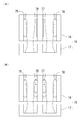
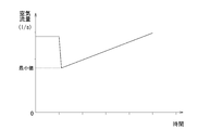
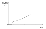
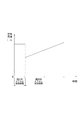
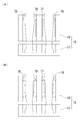
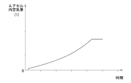
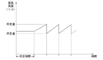
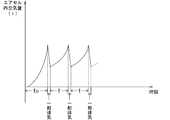
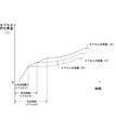
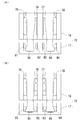
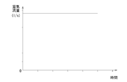
- FIG. 1 is a perspective view of a massage machine according to a first embodiment of the present invention. It is a block diagram of the massage machine concerning a 1st embodiment of the present invention. It is an air supply system figure in the massage machine concerning a 1st embodiment of the present invention. It is an expansion state explanatory view of the leg air cell in the massage machine concerning a 1st embodiment of the present invention. It is change state explanatory drawing of the air flow rate per unit time from the air pump in the massage machine which concerns on the 1st Embodiment of this invention. It is time change explanatory drawing of the air amount in an air cell in the massage machine which concerns on the 1st Embodiment of this invention.
- the massage machine 1 is a chair that supports a seated user, and in detail, a base that is placed on the floor and stably supports the entire chair. 11, a seat portion 12 that supports the user's buttocks above the base portion 11, a backrest portion 13 that supports the user's back on the back side of the seat portion 12, and a user on both the left and right sides of the seat portion 12.
- Arm support 14 for supporting the elbow and forearm, leg support 15 for supporting the user's leg on the front side of the seat 12, an operation unit 30 for receiving various operation inputs of the user, and a plurality of treatments installed. It is the structure provided with the control part 40 which controls the operation
- the base portion 11 is a unit in which the seat portion 12, the backrest portion 13, the armrest portion 14, and the leg support portion 15 that constitute each portion of the chair are integrally attached to support them.
- the seat 12 is attached to the base 11 so that the inclination angle of the seat can be adjusted, and massage is performed by a built-in treatment means while supporting the user's buttocks and thighs on the seat. Is.
- a treatment means of this seat part 12 it is the structure provided with the air cell 71 for hips and the air cell 72 for thighs which expand / contract by supply and discharge of air.
- FIG. 1 has a surface shape that matches the shape of the human back and is arranged so that the inclination angle can be adjusted with respect to the base portion 11 and the seat portion 12, and a treatment means for performing massage is provided therein. It is the composition provided.
- a mechanical unit 50 in which a pair of left and right grind balls 51 as a treatment element that gives a user a stimulus such as kneading and hitting and a drive mechanism 60 that moves the same are integrated, and the mechanical unit 50.
- a frame-like backrest frame 13a that supports each part of the backrest 13 from the inside, and a back air cell 73 that expands and contracts by air supply and discharge by the air pump 70 and a waist
- Each of the air cells 74 is arranged.
- the mechanical unit 50, the back air cell 73, and the waist air cell 74 respectively constitute treatment means for performing massage.
- a pair of side walls provided with treatment means such as air cells on the inner side facing the user are provided on the left and right sides of the backrest 13 so as to protrude from the user's upper arm. You can also make it possible to massage.
- the backrest frame 13a hangs a plurality of horizontal frames in a horizontal direction between a pair of left and right guide frames 13b that support the mechanical unit 50 in the vertical direction of the backrest 13 and restrain the movement in the other direction. It is handed over and connected together to form a substantially ladder-like frame structure.
- the armrests 14 are disposed on both sides of the seat 12 and are formed to stably support the user's forearm even when the backrest 13 changes the reclining angle or the seat 12 tilts. It is a configuration.
- the armrest portion 14 may be provided with an air cell that expands and contracts by supplying and discharging air by the air pump 70 so that the user's forearm can be massaged.
- the said leg support part 15 is located in the front side of the seat part 12, and is arrange
- the leg support portion 15 is formed as a shape having two groove portions 15a each having a size to accommodate the left and right legs of the user, and is attached to the front end of the seat portion 12 so as to be tiltable.
- the leg support cells 17 disposed at the ends of the main body 16 and the leg air cells 75 and 76 as the treatment means disposed on the main body 16 and inflating and contracting by air supply and discharge by the air pump 70. , 77, 78.
- an air cell that expands and contracts by air supply and discharge by the air pump 70 and presses the foot is disposed in the foot support part 17, or a roller that presses the leg while moving up and down.
- the treatment means may be arranged in the main body portion 16.
- Each air cell as a treatment means including the leg air cells 75, 76, 77, 78 of the leg support portion 15 is an air pump as an air supply means via an electromagnetic valve 80a, ..., 80h for each air cell. 70.
- the electromagnetic valves 80a,..., 80h have a first port communicating with the air pump 70, a second port communicating with the air cell, and a third port communicating with the outside, and are controlled by the control unit 40. Accordingly, the first port and the second port are communicated, and the third port is closed and the air pump 70 can supply air to the air cell, and the second port and the third port are communicated. And the state in which the first port is closed and the air in the air cell is exhausted to the outside, and the first port, the second port, and the third port are not communicated with each other.
- This is a known three-way valve that can switch between three states, a state in which the pressure can be maintained, and a detailed description thereof will be omitted.
- These air pumps 70 and electromagnetic valves 80a,..., 80h constitute an air supply / discharge adjustment mechanism for each air cell, and the control unit 40 activates the air pump 70 and the electromagnetic valves 80a,.
- the air cell can be supplied, exhausted, or maintained in pressure, and the air cell can be expanded, contracted, or maintained in a predetermined expanded state.
- the solenoid valves 80a,..., 80h receive a control command from the control unit as exhaust means and are switched to a state in which the air in the air cell is exhausted to the outside. Shrink.
- the air cell is inflated, a pressing force against the air cell contact portion of the body is generated, and when the air cell is contracted, the pressure is released, so that a variety of massage effects can be provided at each air cell position.
- the air cell disposed in each part of the massage machine as a treatment means is made of a flexible material that can be gradually elastically deformed and expanded and contracted in response to a change in the air amount in the air cell due to supply and discharge of air to and from the air cell.
- it is desirable to have an excellent deformation performance that allows a user to feel a small change in the air amount or pressure in the air cell as a change in pressing force.
- By flexibly and delicately deforming the air cell it is possible to improve the massage effect by improving the quality of stimulation by pressing the massage target portion.
- the cover that is placed outside the air cell and covers and protects it is also deformed following the expansion and contraction of the air cell, and the change in the air cell is used as it is. It is preferable to use a flexible and deformable material that is transmitted to the user as a change in touch.
- the operation unit 30 includes a number of switches and display units for receiving various operation inputs to the massage machine, is detachably installed on the stand 31 on the side of the massage machine 1, and transmits operation inputs related to massage to the control unit 40. To do. Note that the position of the stand 31 can be adjusted so that the position of the switch and the display unit of the operation unit 30 is the optimum position for the user.
- the control unit 40 adjusts the other movable parts of the treatment means and the massage machine to a state corresponding to the user based on the detection result obtained by executing the position detection of each part of the user's body in advance. Control for performing appropriate massage is performed on the treatment means and other movable parts based on the operation of the operation unit, treatment contents recorded and set in advance, and information on the detection result.
- the control unit 40 is a computer including a CPU, a memory, an input / output interface, and the like as its hardware configuration, and is a mechanism for operating the computer as the control unit 40 by a program stored in the memory or the like.
- the computer constituting the control unit 40 may be a microcomputer in which a CPU, a memory, a ROM, and the like are integrally formed.
- the computer unit constituting the control unit 40 is disposed in a predetermined space inside the massage machine 1 such as directly under the seat 12 and is in a state where it can communicate with the operation unit 30, and various motors of the mechanical unit 50.
- Seat 12, backrest 13, actuators for tilting leg support 15, air pump 70, solenoid valves 80 a,..., 80 h are electrically connected to each other to detect the position of each part of the user's body.
- the operation of these drive mechanisms is controlled by a control signal output based on a preset position detection program, and by a control signal output based on massage data set at the time of massage execution.
- control unit 40 is also electrically connected to signal output means such as an encoder that outputs the displacement amount of the mechanical unit 50 and each actuator, and the state of the mechanical unit 50, the seat portion 12, the backrest portion 13,
- signal output means such as an encoder that outputs the displacement amount of the mechanical unit 50 and each actuator, and the state of the mechanical unit 50, the seat portion 12, the backrest portion 13,
- the operation control of the driving means such as the motor and the actuator is performed while grasping the state of the leg support 15 such as the inclination.
- control unit 40 controls the mechanical unit 50 to detect the position of each part of the user's body prior to the massage, like the known massage machine, and moves the mechanical unit 50 from the initial position in the backrest 13 to the guide frame 13b.
- a change in pressure on the kneading balls 51 from the user leaning against the backrest 13 and a change in the inclination of the kneading balls 51 are sequentially acquired. Based on the information, the user's shoulder position, spine line, and waist position can also be detected.
- the main power of the massage machine 1 is turned on in a state where the user sits on the massage machine 1 and the back is leaned against the backrest part 13 and the leg support part 15 supports the leg.
- preparatory operations before starting massage such as detecting the user's weight and body shape, reclining angle adjustment of the backrest 13 and the like are completed, and further instructions for executing a massage course etc. are input by the user
- the control unit 40 is about to perform massage by the air cell for the user.
- the air cells 75 and 78 outside the legs of the leg air cells are inflated in advance to be fixed as a kind of wall, and then the air cells 76 and 77 inside the legs are inflated,
- the operation state of each part such as an air pump in the massage (see FIG. 4) for locally pressing the massage target portion will be described.
- control unit 40 sends control commands to the air pump 70 and the electromagnetic valves 80e and 80h in advance to supply air to the leg air cells 75 and 78 located outside the legs, and each air cell 75 is supplied. , 78 are inflated so that the leg is difficult to move outward (see FIG. 4A). In a state where the expanded state of the leg air cells 75 and 78 is maintained, the process proceeds to an expansion process of the leg air cells 76 and 77 on the inner side of the leg for massage.
- control unit 40 sends a control command to the air pumps 70 and the electromagnetic valves 80f and 80g to the air cells 76 and 77 which are located inside the legs and are in a contracted state away from the massage target portion of the user. Then, air is supplied to the air cells 76 and 77 to inflate each air cell. Until the air cell starts supplying air from the contracted state until a predetermined time elapses, the operation of the air pump 70 is controlled so that the air supply has a constant predetermined air flow rate per unit time (see FIG. 5). .
- the predetermined time during which the air flow rate is constant means that the air cell expands from the contracted state to the massage target location of the user, in this case, the inner portion of the leg, until the location can be pressed. This corresponds to the time required for supplying the necessary air amount.
- the hollow portion inside has a predetermined internal volume, and the air pump and the air cell are connected via a pipe such as a pipe or a hose. Immediately thereafter, a change in the amount of air in the air cell is unlikely to occur, and there is a time delay in starting the expansion of the air cell (see FIG. 6).
- the control unit 40 grasps this, the control unit 40 sends a new control command to the air pump 70 and switches the air supply state to the air cells 76 and 77.
- time information is set in advance based on measured data such as the event change and detection value change for each air cell collected in advance, and the actual elapsed time from the start of air supply It may be determined whether or not has reached.
- the control unit 40 first sets the air flow rate per unit time toward the air cells 76 and 77 from the predetermined predetermined amount by the operation control of the air pump 70 in advance. Reduce to a minimum amount. Thereafter, the control unit 40 controls the operation of the air pump 70 so that the air flow rate per unit time toward the air cells 76 and 77 increases from the minimum amount with the passage of time (see FIG. 5). The control unit 40 reduces the air flow rate per unit time toward the air cell to the minimum value when the predetermined time has elapsed from the start of air supply.
- the present invention is not limited to this, and the unit time until the predetermined time elapses. If it is once reduced from the per-air flow rate, it may be reduced to a predetermined set value other than the minimum value.
- the air flow rate toward the air cells 76 and 77 is once reduced to the minimum amount, and then the air cell 76 and 77 starts pressing the massage target portion.
- the air pump 70 has a predetermined constant air flow rate sufficiently larger than the minimum amount at the initial stage where the air cells 76 and 77 are not adjacent to the massage target portion.
- swelling of the air cells 76 and 77 is carried out by operating the air pump 70 so that the air flow rate which goes to the air cells 76 and 77 increases with progress of time.
- the degree of increase in the air amount in the air cell increases (see FIG. 6).
- the degree of change in which the pressing force of the air cells 76 and 77 is increased, and the change in the pressing force is not monotonous, so that the user receiving the pressing force from the air cells 76 and 77 increases the pressing force.
- the air flow rate toward the air cells 76 and 77 by increasing the air flow rate toward the air cells 76 and 77 from the minimum amount, an increase in the air flow rate can be sufficiently secured, and the period during which the air amount in the air cell substantially changes is lengthened.
- the pressure of the air cell is greatly increased by the progress of the pressure accompanying the expansion of the air cells 76, 77, and the stimulation by the pressure can be strongly applied to the massage target portion of the leg, and the massage is efficiently performed. it can.
- the stimulation by the pressure of the air cells 76 and 77 is close to the characteristics of the pressure stimulation in the massage by a person's finger that is strengthened as the pressure progresses, the user can feel it. Smooth transition to a relaxed state.
- the control unit 40 sends a control command for stopping supply of air and maintaining pressure to the air pump 70 and the electromagnetic valves 80f and 80g as necessary. While stopping the supply of air to the air cells 76 and 77, the exhaust state is not performed yet, the expanded state of each air cell can be maintained for a predetermined time, and the pressed state of the massage target portion of the leg can be maintained for a while. .
- control unit 40 sends a control command for stopping the operation to the air pump 70 and the electromagnetic valves 80e,..., 80h, and contracts each air cell by exhaust, a series of leg air cells related to the massage is performed.
- the expansion / contraction process ends.
- the control unit 40 expands and contracts the leg air cells 76 and 77 once, and then repeatedly executes the same expansion / contraction process one or more times at predetermined time intervals. ,..., 80 g may be actuated so that the stimulation by the air cell is repeatedly applied to the massage target portion of the user.
- the air pump 70 is actuated to supply air to the leg air cells 76 and 77, and in the process of expanding the air cell, the air pump 70 is initially supplied with air at a predetermined constant flow rate.
- the control unit 40 operates the air pump 70 so that the air flow rate per unit time toward the leg air cells 76 and 77 increases with time, and the air flow rate is gradually increased.
- the control unit 40 controls the operation of the air pump 70 so that the air flow rate per unit time toward the leg air cells 76 and 77 decreases from a certain predetermined amount to a minimum amount.
- the control unit 40 is configured to perform operation control so that the change in the air flow rate in the air pump 70 continues from a certain predetermined amount to the minimum amount.
- the present invention is not limited to this, and the control unit 40 is shown in FIG.
- the air flow rate in the air pump 70 is changed from the state where the air flow rate is a predetermined amount to the intermediate air flow rate without discontinuously changing the air flow rate to the minimum amount, and the passage of time from this minimum amount.
- the operation of the air pump 70 can be controlled so that the air flow rate increases.
- the control unit 40 determines that the air cell is used only for the expansion process of the leg air cells 76 and 77 inside the leg for massage execution until a predetermined time elapses from the start of air supply to the air cell.
- the air pump 70 is operated as an air supply means so that the air flow rate per unit time toward the air is constant, and after the predetermined time has elapsed, the air pump 70 is adjusted so that the air flow rate toward the air cell increases with time.
- the process of performing a series of controls to operate and inflating the leg air cells 75, 78 outside the legs prior to the expansion of the leg air cells 76, 77 inside the legs is configured as another control.
- the present invention is not limited to this, and the series of controls including a step of making the air flow rate constant and a step of increasing the air flow rate according to the operation of the air supply means through a series of processes of sequentially expanding a plurality of air cells. It is also possible to adopt a configuration in which the controller performs this.
- the air pump 70 is operated so as to keep the air flow rate per unit time toward the air cell constant. It can be set as the structure which controls the action
- control unit 40 sends a control command to the air pumps 70 and the electromagnetic valves 80e and 80h to the air cells 75 and 78 that are located outside the legs and are in a contracted state.
- the air cell is inflated individually. Until the air cell starts to supply air from the contracted state and a predetermined time elapses, the operation of the air pump 70 is controlled so that the air supply has a predetermined air flow rate per unit time (see FIG. 8).
- the expanded leg air cells 75 and 78 are adjacent to the outside of the legs, forming a kind of wall and the legs are outside.
- the control unit 40 grasps that the time required to supply the necessary amount of air until a state in which it is difficult to move is generated, the control unit 40 controls the supply of air to the solenoid valves 80e and 80h and stops holding the pressure. A command is sent to stop the supply of air to the leg air cells 75 and 78, and the exhaust state is not performed yet, and the expanded state of each air cell is maintained.
- control unit 40 newly sends a control command to the air pump 70 and the electromagnetic valves 80f and 80g, supplies air to the air cells 76 and 77, and expands each air cell.
- control unit 40 controls the operation of the air pump 70 so that the air flow rate per unit time toward the air cells 76 and 77 increases with time (see FIG. 8).
- the air pump 70 supplies air to the leg air cells 75 and 78 at a constant flow rate, and after a predetermined time has elapsed, gradually increases the air flow rate to the leg air cells 76 and 77.
- the air pump 75 supplies air at a predetermined constant air flow rate.
- 78 is in a state where it is difficult for the leg to actually move adjacent to the leg, and the time required to start pressing the leg massage can be made as short as possible.
- the air pump 70 is operated so as to increase the air flow rate toward the air cells 76, 77 with the passage of time, so that the pressure of the legs accompanying the expansion of the air cells 76, 77 proceeds.
- the greater the degree the greater the degree of change in the air amount in the air cell.
- the degree of change in which the pressing force of the air cells 76 and 77 becomes strong is increased as in the above-described embodiment, so that the user who receives the pressure from the air cells 76 and 77 can easily feel the pressing force with the increasing change. It gives a clear massage feeling and enhances the massage effect.
- the control unit 40 issues a control command to stop the operation to the air pump 70 and the electromagnetic valves 80e,.
- the air cells are sent out and contracted by exhaust.
- the control unit 40 uses the inside of the lower knee portion of the leg as a massage target location, and the air pump 76 and 77 for the legs facing this location is in a predetermined inflated state.
- all the leg air cells 75, 76, 77, 78 are inflated at the same time, and a predetermined portion of the leg below the knee is pressed from the inside and outside of the leg.
- the control unit can also control the operation of each unit so as to be able to perform a massage that presses the legs so as to sandwich the legs.
- the configuration of the massage machine itself is the same as that of the first embodiment, and detailed description thereof is omitted.
- all the leg air cells 75, 76, 77, 78 that is, the air cells on the outside and inside of the leg are inflated at the same time so that the massage target portion of the lower knee part of the leg is sandwiched between the air cells.
- the operation state of each part, such as an air pump, in the massage (see FIG. 9) that is pressed onto the body will be described.
- the control unit 40 is provided with air pumps 70 and solenoid valves 80e for the leg air cells 75, 76, 77, and 78 that are located inside and outside the legs and are in a contracted state away from the massage target location of the user.
- a control command is sent to 80h to supply air to the leg air cells 75, 76, 77, 78, and to inflate each air cell.
- the operation of the air pump 70 is controlled so that the air supply has a constant predetermined air flow rate per unit time (see FIG. 5).
- the predetermined time when the air flow rate is constant is the same as in the first embodiment, and each air cell is adjacent to the massage target portion of the user from the contracted state, in this case, the inner and outer portions of the leg below the knee, This corresponds to the time required to supply the necessary amount of air for expanding these locations until they can be pressed.
- the expanded leg air cells 75, 76, 77, 78 are adjacent to the massage target part from both the inner and outer sides and sandwich the part from both sides.
- the control unit 40 grasps that the pressable state has been reached, for example, from an event such as an increase in the air pump supply load or a change in the detected value of the pressure sensor, as in the first embodiment, the control unit 40 sends a new control command to the air pump 70 to switch the air supply state to the leg air cells 75, 76, 77, 78.
- the control unit 40 first controls the operation of the air pump 70 so that the control unit 40 per unit time heads toward the leg air cells 75, 76, 77, 78.
- the air flow rate is decreased from the predetermined predetermined amount to a preset minimum amount.
- the control unit 40 controls the operation of the air pump 70 so that the air flow rate per unit time toward the leg air cells 75, 76, 77, 78 increases from the minimum amount over time (see FIG. 5).
- the air pump 70 supplies air at a predetermined constant air flow rate sufficiently larger than the minimum amount, The time until all the leg air cells 75, 76, 77, 78 actually start pressing adjacent to the massage target portion can be made as short as possible.
- the air flow rate toward the leg air cells 75, 76, 77, 78 is increased with time.
- the degree of the increase in the air amount in the air cell increases as the pressure accompanying the expansion of the leg air cells 75, 76, 77, 78 advances (see FIG. 6). .
- the degree of change in the pressing force to the massage target portion also increases, and the pressure that the user who receives the pressure to pinch the leg from the leg air cells 75, 76, 77, 78 is pinched accordingly. It becomes easy to perceive with the change that strengthens, and the user can surely grasp it as a stimulus that clearly increases the force pinched from both sides by the air cells 75, 76, 77, 78 for legs, and a clear massage feeling to the user Give it a massage effect.
- the leg air cells 75, 76, 77, 78 by increasing the air flow rate toward the leg air cells 75, 76, 77, 78 from the minimum amount, a sufficient increase in the air flow rate can be secured, and the leg air cells 75, 76, 77 are secured.
- the pressure of the air cell is greatly increased by the progress of the pressure accompanying the expansion of 78, and the stimulation sandwiched from both sides can be strongly applied to the massage target portion of the leg, and the massage can be executed efficiently.
- the stimulation caused by pressing between the leg air cells 75, 76, 77, 78 from both sides of the leg is felt by the user as being close to the characteristics of the pressing stimulation in the massage with a human finger, which becomes stronger as the pressing progresses. Therefore, the user can be smoothly shifted to a relaxed state by such massage with an air cell.
- the control unit 40 controls the supply of air to the air pump 70 and the electromagnetic valves 80e,.
- a command is sent to stop the supply of air to the leg air cells 75, 76, 77, 78, while the exhaust is not performed yet, and the expansion state of each air cell is further maintained for a predetermined time, and the leg massage is performed. It is also possible to maintain a pressing state that sandwiches the target portion for a while.
- control unit 40 sends a control command for stopping the operation to the air pump 70 and the electromagnetic valves 80e,..., 80h, and contracts each air cell by exhaust, a series of leg air cells related to the massage is performed.
- the expansion / contraction process ends.
- the control unit 40 expands the leg air cells 75, 76, 77, 78 once and further contracts them, and then performs the same expansion / contraction process one or more times at predetermined time intervals.
- the air pump 70 and the electromagnetic valves 80e,..., 80h are actuated so as to be repeatedly executed, and the stimulation by pinching the legs by the press of the air cells 75, 76, 77, 78 for the legs to the massage target portion of the user. May be given repeatedly.
- the control unit 40 expands the air cell during massage, specifically, until the air cell starts to supply air from the contracted state until a predetermined time elapses.
- the air pump 70 or the like is operated so as to keep the air flow rate per unit time toward the air cell constant.
- the control unit 40 operates the air pump 70 and the like to increase the air flow rate per unit time toward the air cell.
- the control unit is provided for the air cell that is arranged closer to the user side, such as adjacent to the massage target location of the user even in the contracted state.
- the predetermined time for which the air flow rate is constant is set shorter, that is, the air flow rate per unit time toward the air cell increases from the time immediately after the start of air supply at a constant flow rate to the air cell by the air pump.
- An air pump or the like may be operated.
- the configuration of the massage machine itself is the same as that of the first embodiment, and detailed description thereof is omitted.
- an air pump or the like in a massage that expands the back air cell 73 and presses the massage target portion on the back supported by the backrest portion 13 of the seated user from the rear side.
- the operation state of each part will be described.
- the control unit 40 sends control commands to the air pump 70 and the electromagnetic valve 80c, supplies air to the back air cell 73, and expands the air cell.
- the operation of the air pump 70 is controlled so that the air supply is maintained at a constant predetermined amount of air flow per unit time until the predetermined time has elapsed since the air supply for the back air cell 73 is started from the contracted state (see FIG. 11).
- the predetermined time for which the air flow rate is constant is the same as in the first embodiment, and the air cell is adjacent to the massage target portion of the user, in this case, the back from the contracted state, and this portion can be pressed.
- an extremely short time such as a time delay from the start of air supply of the air pump to the start of expansion of the air cell is set based on the internal volume of the air cell hollow portion and the pipe connection state (see FIG. 11).
- control unit 40 grasps that the back air cell 73 has actually reached a state where the back, which is a massage target portion, can be pressed after the predetermined time has elapsed since the start of air supply to the back air cell 73, The control unit 40 sends a new control command to the air pump 70 and switches the air supply state to the back air cell 73.
- the control unit 40 first sets the air flow rate per unit time toward the back air cell 73 in advance from the predetermined predetermined amount by controlling the operation of the air pump 70. Reduce to a minimum amount. Thereafter, the control unit 40 controls the operation of the air pump 70 so that the air flow rate per unit time toward the back air cell 73 increases from the minimum amount with the passage of time (see FIG. 11).
- the air flow rate toward the back air cell 73 that presses the back which is the massage target portion, is started to be supplied to the back air cell 73 as a constant flow rate, and after a short predetermined time has elapsed, it is newly increased with the passage of time.
- the air pump 70 By operating the air pump 70 as described above, the degree of the increase in the air amount in the air cell increases as the pressure accompanying the expansion of the back air cell 73 progresses (see FIG. 12).
- the degree of the pressure change to the massage target portion is also increased, and accordingly, the user who receives the pressure from the back air cell 73 can easily feel the pressure with the increasing change.
- the user can surely grasp the air cell from the early stage of expansion of the air cell, and the massage effect can be enhanced by giving the user a clear massage feeling.
- the air flow rate toward the back air cell 73 can be sufficiently increased and the air cell can be sufficiently secured.
- the period during which the amount of internal air changes substantially can be lengthened, and the pressing force of the air cell is greatly increased by the progress of the pressing accompanying the expansion of the back air cell 73, so that the back massage target portion is stimulated by pressing. Can give powerfully and can perform massage efficiently.
- the stimulation by the pressure of the air cell 73 for the back is close to the characteristics of the pressure stimulation in the massage by a person's finger that is strengthened as the pressure progresses, the user can feel it. Smooth transition to a relaxed state.
- control unit 40 sends an air supply stop and pressure holding control command to the air pump 70 and the electromagnetic valve 80c as necessary to supply the back air cell 73 to the back air cell 73. While air supply is stopped, exhaust is not performed yet, and the expanded state of the air cell can be further maintained for a predetermined time, and the pressed state of the back can be maintained for a while.
- control unit 40 sends an operation stop control command to the air pump 70 and the electromagnetic valve 80c and contracts the back air cell 73 by exhaust, a series of expansion and contraction processes of the back air cell 73 related to the massage are performed. Ends.
- control unit 40 expands the back air cell 73 once and further contracts, and then repeatedly executes the same expansion / contraction process one or more times at predetermined time intervals.
- the air pump 70 and the electromagnetic valve 80c may be operated so that stimulation by pressing the back air cell 73 is repeatedly applied to the massage target portion of the user.
- the control unit 40 increases the air flow rate when controlling the operation of the air pump 70 or the like so as to increase the air flow rate per unit time toward the air cell.
- the ratio is constant, that is, the control is performed so that the time change of the air flow rate becomes linear on the graph, the control unit 40 is not limited to this, and the increase rate of the air flow rate changes with time.
- the air pump 70 can be configured to operate. Specifically, if the increase rate of the air flow rate is set so as to increase as time passes (see FIG. 13), the pressing force increases as the expansion proceeds. It is possible to respond appropriately to the situation where the change is desired to be large, for example, expansion when the air cell is in a contracted state and adjacent to the massage target part.
- the rate of increase in the air flow rate is set so as to decrease as time passes (see FIG. 14), a situation in which the change in the pressing force is suppressed as the expansion progresses, for example, when the air cell is in a contracted state, It is possible to appropriately cope with the expansion in the case of pressing away so as to sandwich the massage target portion between the two air cells.
- FIG. 15 and FIG. 16 show the air supply state of still another embodiment. Unless otherwise specified, the configuration is the same as described above, and the details of the air supply state will be described below.
- the control unit sends a control command so that the air flow rate (supply speed) per unit time is set to a predetermined constant amount, desirably the maximum amount or an amount as close as possible to the maximum amount.
- the air supply state to the air cell is switched after a predetermined time when the air cell is in a semi-expanded state, and the air flow rate per unit time is reduced to a minimum amount or a predetermined amount. Then, when the air supply speed is gradually increased from the reduced air supply speed to the air cell in a semi-expanded state, the pressure can be gradually increased while keeping a comfortable pressure, so that the massage effect for the user is improved.
- the semi-expanded state is a state where the pressing force necessary for the massage by the air cell has not been reached, and there are various degrees depending on the treatment location, how to install the air cell, and the like.
- FIG. 17 shows still another embodiment, and FIGS. 17A and 17B show a control command to make the air flow rate per unit time a certain predetermined amount, desirably the maximum amount or the maximum amount as close as possible.
- FIG. 17 (A) shows a pattern in which the air flow rate per unit time gradually decreases toward the minimum amount or a predetermined amount after the amount is sent, and then the speed increases.
- FIG. It is a pattern in which the speed changes.
- FIG. 18 and FIG. 19 show the air supply state of still another embodiment. Unless otherwise specified, the configuration is the same as described above, and the details of the air supply state will be described below.
- control unit sends out a control command, and appropriately sets and sends out the air flow rate (supply speed) per unit time. Also in this case, it is desirable to send an amount close to the maximum amount within a predetermined time, but there is no particular limitation as long as the air supply speed is appropriate.
- the air supply state to the air cell is switched and the air supply speed is gradually increased from the air supply speed to expand the air cell.
- the pressure can be gradually increased while keeping a comfortable pressure, the massage effect for the user is improved.
- the expansion further proceeds, further expansion becomes difficult.
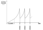
- a part of air is discharged at a timing shown in FIG. The expansion is started again after the expansion state. Note that while part of the air is being discharged, the pump may be temporarily stopped or may be continuously driven.
- FIGS. 20 and 21 show the air supply state of still another embodiment. Unless otherwise specified, the configuration is the same as described above, and the details of the air supply state will be described below.
- control unit sends out a control command and appropriately sends out an air flow rate (air supply speed) per unit time.
- control is performed to gradually increase the air supply speed from the beginning without setting the predetermined time.
- the pressure can be gradually increased while keeping a comfortable pressure, the massage effect for the user is improved.
- a part of air is exhausted at the timing shown in FIG. 21 by using exhaust means such as a solenoid valve.
- exhaust means such as a solenoid valve.
- the supply of air by the pump is stopped, the air cell is brought into a semi-expanded state, and then expansion is started again.
- the air supply speed is controlled so as to increase from a predetermined amount, but FIG. 20 shows an example in which the predetermined amount is 0 (zero).
- the semi-expanded state is a state where the pressing force necessary for the massage by the air cell has not been reached, and there are various degrees depending on the treatment location, how to install the air cell, and the like.
- the time t until the further expansion becomes difficult from the half-expanded state is until the further expansion becomes difficult when the air cell gradually increases the air supply speed from the contracted state. Is set to be shorter than the time t0, so that the next exhaust is performed immediately from the expanded state, and the period during which further expansion is difficult and the air supply speed cannot be gradually increased is reduced as much as possible. A stimulus that clearly increases the pressing force can be experienced better.
- FIG. 22 and FIG. 23 show the air supply state of still another embodiment. Unless otherwise specified, the configuration is the same as described above, and the details of the air supply state will be described below.
- the control part shown by this embodiment performs different control according to capacity
- the predetermined time is set short for an air cell with a small capacity, and the predetermined time is set long for an air cell with a large capacity.
- air supply is performed so that the air flow rate gradually increases after each air cell has a similar swelling state (semi-expanded state) regardless of the capacity of the air cell.
- the control to be performed can be performed, the same expansion change can be given regardless of the size of the air cell, and an excellent massage effect can be obtained.
- the predetermined time may be varied depending on the difference in the amount of air that can be inflated until it is adjacent to the massage target location of the user.
- the amount of air that can be inflated until it is adjacent to the massage target location of the user is, for example, an air cell that is disposed for the purpose of sandwiching legs, arms, etc.
- the air cell disposed in the backrest portion for the purpose of massage by pressing is set short for a predetermined time.
- FIG. 4 shows a case of a leg air cell
- FIG. 10 shows a case of a back air cell.
- the predetermined time time until reaching the half-expanded state
- the air flow rate per hour is maximum (or a predetermined amount close to the maximum) is set to a different set value.
- the foot air cells 81 to 84 shown in FIG. 24 are provided to hold the foot from above and hold the foot from above. Therefore, the predetermined time for setting the air flow rate per unit time to the maximum (or a predetermined amount close to the maximum) is set long, and the sole air cells 85 and 86 provided on the sole maximize the air flow rate per unit time (or maximum).
- the predetermined time (predetermined amount close to) may be as short as possible.
- control first, air supply to the foot air cells 81 to 84 is started, the air cells are in a semi-expanded state, and then air per unit time toward the foot air cells 81 to 84 and the sole air cells 85 and 86 The flow rate changes over time.
- the foot air cells 81 to 84 are controlled to maximize the air flow rate per unit time from the beginning to the end (or a predetermined amount close to the maximum), and the foot air cells 85 and 86 are set to the maximum air flow rate.
- the predetermined time may be omitted, and control may be performed to supply air so that the air flow rate gradually increases from the beginning.
- the pressure in the air cell increases, and the control for increasing the air supply speed as the performance of the pump is performed.
- exhaust control is executed when the actual air supply speed does not match the actual air supply speed, it is possible to more strongly experience a stimulating massage that clearly increases the pressing force.
- the control unit performs control to vary the discharge capacity of the air supply means so that the air flow rate per unit time toward the air cell increases with time.
- the control unit performs control to vary the discharge capacity of the air supply means so that the air flow rate per unit time toward the air cell increases with time.
- a massage machine having an air cell that expands and contracts due to air supply and discharge, and performs massage to the user's body by pressing accompanying the expansion of the air cell, air is supplied to the air cell connected to the air cell
- An air supply means arranged as possible, and a control unit that controls at least an air supply state to the air cell by the air supply means, wherein the control unit has an air flow rate per unit time toward the air cell.
- a massage machine characterized by controlling the operation of the air supply means so as to change over time.
- the massage machine of Appendix A has the effect of realizing various massages.
- Appendix B In the massage machine according to Appendix A, in the process in which the control unit expands the air cell, air supply to the air cell is started from the contracted state of the air cell until a predetermined time elapses.
- the control unit changes the air flow rate per unit time toward the air cell so that the air flow rate changes with time.
- a massage machine that controls the operation of an air supply means.
- the air supply means in the process of supplying air to the air cell by operating the air supply means and inflating the air cell, the air supply means is initially operated in the air supply state with the maximum flow rate, while the predetermined time is When the time has elapsed, the control unit changes the operating state of the air supply means, and causes air to be supplied to the air cell so that the air flow rate changes with time.
- expansion and contraction are performed in the air cell having a certain size, the pressure change to the massage target portion becomes agile, and the user receiving the pressure from the air cell becomes easy to feel with the change in the pressure, and from the air cell
- the user can be surely grasped as a stimulus that clearly changes the pressing force, giving a clear massage feeling and enhancing the massage effect.
- Appendix C In the massage machine according to Appendix A, in the process in which the control unit expands the air cell, the air cell is in the stage from the contraction state of the air cell to the start of air supply to the air cell until a predetermined time elapses.
- the control unit reduces the air flow rate per unit time toward the air cell to a predetermined set amount or the minimum amount.
- a massaging machine characterized by controlling the operation of the air supply means so as to change the air flow rate per unit time of air toward the air cell after being once reduced.
- the air supply means sets the maximum air flow rate toward the air cell, After the predetermined time has elapsed, the air flow toward the air cell is once reduced to a predetermined amount, and the air cell changes the air flow rate at the same time as the air cell starts to press the massage target location.
- the air supply means supplies the maximum amount of air so that the time until the air cell starts to press the massage target portion is made as short as possible.
- the massage target can be sufficiently pressed, even if the air flow rate toward the air cell is reduced to a predetermined amount,
- the pressure of the air cell is greatly increased by the progress of the pressure accompanying the expansion of the cell, and the stimulation by the pressure can be strongly applied to the massage target portion of the user, the massage can be performed efficiently, and the user's massage can be performed efficiently.
- the above effect can be further exerted when the transition to the relaxed state is further promoted, and particularly when the speed of the air flow rate to be reduced is reduced to the minimum.
- Appendix D In the massage machine according to any one of Appendixes A to C, when the predetermined time has elapsed, the control unit controls the operation of the air exhaust unit and the air supply unit of the air cell. Massage machine.
- the amount of air in the air cell can be reduced by the exhaust means, and the same air cell expansion / contraction operation can be repeated.
- Appendix E The massage machine according to any one of Appendixes B to D, wherein the predetermined time with the maximum air flow rate per unit time is set to a different set value depending on a treatment location. Machine.
- an appropriate massage can be performed at a treatment location using an air cell in the massage machine.
- Air supply to the air cell is connected to the air cell Air supply means arranged as possible, and a control unit that controls at least the air supply state to the air cell by the air supply means, and the control unit expands the air cell from the contracted state of the air cell to the air cell.
- the air supply means is operated so that the air flow rate per unit time toward the air cell is constant.
- the operation of the air supply means is controlled so that the flow rate per unit time toward the head increases with the passage of time. That massage machine.
- the air supply means in the process of supplying air to the air cell by operating the air supply means and inflating the air cell, the air supply means is initially operated as a predetermined constant flow rate air supply state, When the predetermined time elapses, the control unit changes the operating state of the air supply means to supply air to the air cell so that the air flow rate increases with time.
- the control unit changes the operating state of the air supply means to supply air to the air cell so that the air flow rate increases with time.
- Appendix G In the massage machine according to Appendix F, when the control unit operates the air supply means so that the air flow rate per unit time toward the air cell is constant, and the predetermined time has elapsed, the air cell The air flow per unit time toward the air cell is once reduced to a predetermined minimum amount, and then the operation of the air supply means is controlled so as to increase the air flow rate per unit time toward the air cell from the minimum amount.
- the control unit operates the air supply means so that the air flow rate per unit time toward the air cell is constant, and the predetermined time has elapsed
- the air cell The air flow per unit time toward the air cell is once reduced to a predetermined minimum amount, and then the operation of the air supply means is controlled so as to increase the air flow rate per unit time toward the air cell from the minimum amount.
- the air supply means when the air cell starts to supply air from the contracted state in the process of expanding the air cell, the air supply means operates to maintain the air flow rate toward the air cell at a constant predetermined amount. Then, after a predetermined time has elapsed, after the air flow rate toward the air cell is once reduced to the minimum amount, the air supply means gradually increases the air flow rate from the minimum amount together with the start of pressing the massage target location by the air cell, In the initial stage when the air cell is not properly pressing the massage target location, the air supply means supplies air at a predetermined air flow rate that is not the minimum amount, and the time until the air cell starts to press the massage target location is determined.
- the air flow rate can be increased from the minimum amount to ensure a sufficient increase in the air flow rate, and the pressure of the air cell can be greatly increased by the progress of the air cell expansion. Stimulation by pressing can be strongly applied, massage can be performed efficiently, and the transition of the user to a relaxed state by massage can be further promoted.
- the control unit changes the air cell from the contracted state to the massage target location of the user from the contracted state for a predetermined air flow rate per unit time toward the air cell.
- the air supply means is actuated by setting the time required to supply the amount of air that can be expanded to be adjacent.
- the air supply means is operated in the air supply state at a predetermined constant flow rate until the air cell is adjacent to the massage target location, while the air cell is the massage target.
- the control unit changes the operating state of the air supply means and causes the air cell to appropriately press the massage target part by causing the air supply to gradually increase.
- the control related to the operation of the air supply means can be simplified to improve reliability, and in the situation where the air cell actually presses the massage target location, While pressing with the expansion of the air cell progresses, the user can be surely given a stimulus by pressing while making the user aware of changes in pressing force. It is causing an excellent massage effect become stronger pressing stimulus to.
Landscapes
- Health & Medical Sciences (AREA)
- Epidemiology (AREA)
- Pain & Pain Management (AREA)
- Physical Education & Sports Medicine (AREA)
- Rehabilitation Therapy (AREA)
- Life Sciences & Earth Sciences (AREA)
- Animal Behavior & Ethology (AREA)
- General Health & Medical Sciences (AREA)
- Public Health (AREA)
- Veterinary Medicine (AREA)
- Dermatology (AREA)
- Massaging Devices (AREA)
Abstract
エアセルに対する空気供給手段を適切に作動させて、膨張するエアセルから身体のマッサージ対象箇所に好ましい押圧刺激を加えられ、マッサージ効果を効率よく付与できるマッサージ機である。マッサージ機が単位時間あたりの空気流量が時間経過と共に増加するようエアセルへの空気供給を行うことで、エアセルの膨張に伴う押圧が進行するほど、エアセル内空気量の変化の度合いが大きくなるのに伴い、マッサージ対象箇所への押圧力変化の度合いも大きくなり、エアセルから押圧を受ける使用者は、押圧力をその強まる変化と共に感じ取りやすくなり、エアセルからの押圧力を明瞭に増大する刺激として捉えることとなる。
Description
本発明は、空気給排で膨縮するエアセルを有し、エアセルの膨張変形に伴う押圧で使用者のマッサージ対象箇所に対しマッサージを実行するマッサージ機に関する。
使用者の身体を支持しつつマッサージを実行する椅子式のマッサージ機は、揉み玉等の施療手段を用いて、使用者の肩や背中、腰等、体後面部分を中心にマッサージを実行するものとされている。こうしたマッサージ機において、揉み玉以外の施療手段としては、空気の給排で膨縮する空気袋(エアセル)が広く使用されている。
このエアセルを用いた従来のマッサージ機では、座部や背もたれ部にエアセルを配置し、臀部や背中等のマッサージ対象箇所をエアセルの膨張により押圧するマッサージを可能とする他、脚を支持するオットマン等に複数のエアセルを配置して、各エアセルを膨張させて脚を挟むように押圧するマッサージを可能とする仕組みを有するものもあった。
こうした従来のマッサージ機で、エアセルによるマッサージの強弱を調整する場合、エアセルに対し空気を供給するエアポンプの吐出能力を調整するのが一般的であった。ただし、弱マッサージを行う場合に、吐出能力を単純に下げることで生じる弊害を避けるために、強弱によらずいったんエアポンプを吐出能力大の状態で起動し、その後、マッサージの強弱設定に応じてエアポンプの吐出能力を低下させるよう制御を行うものが提案されている。
このようなエアセルへの空気の吐出能力を空気供給中に調整しつつマッサージを行う従来のマッサージ機の一例として、特開2005-349138号公報に開示されるものがある。
従来のマッサージ機は、前記特許文献に示される構成とされており、空気袋に対するポンプの吐出能力を可変とし、マッサージの強弱設定に関わりなくエアポンプを吐出能力大の状態で起動し、その後強弱設定に応じてエアポンプの吐出能力を低下させるものとなっている。
そして、前記特許文献に記載のマッサージ機では、強いマッサージを行う場合、起動時の吐出能力大の状態を維持して、すなわち空気袋への吐出量を一定として空気供給を行うこととなる(図25参照)。しかしながら、こうした吐出量を一定として空気供給がなされる場合、空気袋が短時間で最大膨張状態に達してしまう上、空気袋が最大膨張状態に近付くにつれて空気袋の内部空気量(体積)や内部圧力の変化が単調になるため(図26参照)、エアセルからの押圧力を受ける使用者は、膨張の進行と共に、押圧を単調な刺激として受け取るようになって、マッサージとしての押圧刺激への感受性が鈍くなり、結果として、使用者に対しマッサージの効果を十分に付与できないという問題があった。
さらに、弱いマッサージを行う場合には、エアポンプを吐出能力大で起動した後、マッサージの強弱設定に応じて吐出能力を調整し、空気袋への吐出量を少なくして空気供給を行うことから、空気袋の膨張進行に伴う空気袋の内部空気量や内部圧力の変化がより一層緩慢なものになる。そのため、エアセルからの押圧力を受ける使用者は、押圧による刺激が一層鈍ったように感じ、その分マッサージ効果も劣ったものになってしまうという課題を有していた。
こうした従来のマッサージ機でのマッサージに対し、人の手で行うマッサージは、マッサージ動作における押圧力の伝達の特性から、押圧が進むほど押圧力が強まり、より力強い刺激を与えるものとなる。従って、前記従来のマッサージ機でのマッサージは、人の手で行うマッサージと、マッサージに係る刺激の質が大きく異なるものであるといえ、その点からも、マッサージを受ける人に違和感を与え、マッサージで人をリラックス状態に移行させることは容易ではない、という課題を有していた。
本発明は前記課題を解消するためになされたもので、エアセルに対する空気供給手段を適切に作動させて、膨張するエアセルから身体のマッサージ対象箇所に好ましい押圧刺激を加えられ、優れたマッサージ効果を効率よく付与できるマッサージ機を提供することを目的とする。
本発明の開示に係るマッサージ機は、空気の給排により膨縮変形するエアセルを有し、エアセルの膨張に伴う押圧で使用者の身体へのマッサージを実行するマッサージ機において、前記エアセルに接続されてエアセルに対し空気供給可能として配設される空気供給手段と、少なくとも当該空気供給手段によるエアセルに対する空気供給状態を制御する制御部とを備え、前記制御部は、空気のエアセルに向かう単位時間あたりの空気流量が時間の経過と共に増加するように、空気供給手段の作動を制御するものである。
このように本発明の開示によれば、空気の流量速度が時間経過と共に増加するようエアセルへの空気供給を行わせる。これにより、エアセルの膨張に伴う押圧が進行するほど、エアセル内空気量の変化の度合いが大きくなるのに伴い、マッサージ対象箇所への押圧力変化の度合いも大きくなって、エアセルから押圧を受ける使用者が、押圧力をその強まる変化と共に感じ取りやすくなり、エアセルからの押圧力を明瞭に増大する刺激として使用者が確実に捉えることができ、明確なマッサージ感を与えられ、マッサージ効果を高められる。加えて、エアセルの押圧による刺激を、押圧進行と共に強まる人の手によるマッサージにおける押圧刺激の特徴に近いものとして体感させることができ、エアセルでのマッサージによっても使用者をリラックス状態へスムーズに移行させられる。
また、本発明の開示に係るマッサージ機は必要に応じて、空気の給排により膨縮変形するエアセルを有し、エアセルの膨張に伴う押圧で使用者の身体へのマッサージを実行するマッサージ機において、前記エアセルに接続されてエアセルに対し空気供給可能として配設される空気供給手段と、少なくとも当該空気供給手段によるエアセルに対する空気供給状態を制御する制御部とを備え、前記制御部は、エアセルを膨張させる過程で、エアセルの収縮状態からエアセルに対する空気供給を開始して所定時間が経過すると、空気のエアセルに向かう単位時間あたりの空気流量が時間の経過と共に増加するように、空気供給手段の作動を制御するものである。
このように本発明の開示によれば、空気供給手段が作動してエアセルに空気を供給し、エアセルを膨張させる過程で、所定時間経過すると、制御部が空気供給手段の作動状態を変更して、空気の流量が時間経過と共に増加するようエアセルへの空気供給を行わせる。これにより、エアセルに空気がある程度供給された状態から、徐々に給気速度を上げながら膨張させることでエアセルの膨張に伴う押圧が進行するほど、エアセル内空気量の変化の度合いが大きくなるのに伴い、マッサージ対象箇所への押圧力変化の度合いも大きくなって、エアセルから押圧を受ける使用者が、押圧力をその強まる変化と共に感じ取りやすくなり、エアセルからの押圧力を明瞭に増大する刺激として使用者が確実に捉えることができ、明確なマッサージ感を与えられ、マッサージ効果を高められる。加えて、エアセルの押圧による刺激を、押圧進行と共に強まる人の手によるマッサージにおける押圧刺激の特徴に近いものとして体感させることができ、エアセルでのマッサージによっても使用者をリラックス状態へスムーズに移行させられる。
また、本発明の開示に係るマッサージ機は必要に応じて、空気の給排により膨縮変形するエアセルを有し、エアセルの膨張に伴う押圧で使用者の身体へのマッサージを実行するマッサージ機において、前記エアセルに接続されてエアセルに対し空気供給可能として配設される空気供給手段と、少なくとも当該空気供給手段によるエアセルに対する空気供給状態を制御する制御部とを備え、前記制御部は、エアセルを膨張させる過程で、エアセルの収縮状態からエアセルに対する空気供給を開始して所定時間が経過すると、空気のエアセルに向かう単位時間あたりの空気流量を減らした後、エアセルに向かう単位時間あたりの空気流量を増加させるように、空気供給手段の作動を制御するものである。
このように本発明の開示によれば、エアセルが膨張する過程で、エアセルが収縮状態から空気を供給開始され、所定時間経過後、空気供給手段がエアセルに向かう空気流量を一度減らした上で、エアセルによるマッサージ対象箇所の押圧開始と共に空気供給手段が空気流量を徐々に増加させていくことにより、エアセルがマッサージ対象箇所を適切に押圧していない初期段階では、空気供給手段が所定の空気流量で空気を供給する一方、所定時間が経過してエアセルがマッサージ対象箇所を十分に押圧できる段階では、エアセルに向かう空気流量を一旦減らしてから増加させて空気流量の増分を十分に確保することができ、エアセルの膨張に伴う押圧の進行でエアセルの押圧力を大幅に増加させて、使用者のマッサージ対象箇所に押圧による刺激を強力に与えることができ、効率よくマッサージを実行でき、マッサージによる使用者のリラックス状態への移行をより一層促せる。
特に所定時間経過後の空気のエアセルに向かう単位時間あたりの空気流量は直前の単位時間あたりの空気流量に比べ出来るだけ多く減じた場合に上記効果がより一層発揮できる。
また、本発明の開示に係るマッサージ機は必要に応じて、排気手段を備え、前記制御部は、空気のエアセルに向かう単位時間あたりの空気流量が時間の経過と共に増加するように、空気供給手段の作動を制御した後に、前記排気手段でエアセル内の一部の空気を排出させて、その後に再度空気のエアセルに向かう単位時間あたりの空気流量を時間の経過と共に増加するように、空気供給手段の作動を制御するものである。
このように本発明の開示によれば、上記効果に加え、排気手段によりエアセル内の空気量を減少させることが出来、マッサージ効果の高い膨縮動作を繰り返し行うことが可能となる。
また、本発明の開示に係るマッサージ機は必要に応じて、前記制御部が、前記所定時間を、エアセルが収縮状態から使用者のマッサージ対象箇所に隣接するまで膨張可能な空気量の供給に要する時間に設定して、空気供給手段を作動させるものである。
このように本発明の開示によれば、収縮状態のエアセルが膨張する過程で、エアセルがマッサージ対象箇所に隣接して押圧を開始すると、制御部が空気供給手段の作動状態を変更して、空気の流量が徐々に増加するよう空気供給を行わせることにより、エアセルがマッサージ対象箇所を適切に押圧していない状況では、空気供給手段の作動に係る制御を簡略にして信頼性を高められると共に、エアセルがマッサージ対象箇所を実際に押圧する状況では、エアセルの膨張に伴う押圧が進行する中、使用者に対し押圧力の強まる変化を意識させつつ押圧による刺激を確実に付与でき、次第に強くなる押圧刺激で優れたマッサージ効果を生じさせられる。
また、本発明の開示に係るマッサージ機は必要に応じて、前記制御部が、前記所定時間を、エアセルの容量に応じて設定して、空気供給手段を作動させるものである。
このように本発明の開示によれば、容量の違う各エアセルが同様の膨らみ具合となってから、空気の流量が徐々に増加するよう空気供給を行わせる制御を行わせることが出来、エアセルがマッサージ対象箇所を実際に押圧する状況では、エアセルの膨張に伴う押圧が進行する中、使用者に対し押圧力の強まる変化を意識させつつ押圧による刺激を確実に付与でき、次第に強くなる押圧刺激で優れたマッサージ効果を生じさせられる。
(本発明の第1の実施形態)
以下、本発明の第1の実施形態に係るマッサージ機を前記図1ないし図6に基づいて説明する。
前記各図において本実施形態に係るマッサージ機1は、着座した使用者を支える椅子状のものであり、詳細には、床面上に載置されて椅子全体を安定的に支持する基台部11と、この基台部11の上方で使用者の臀部を支える座部12と、この座部12の後側で使用者の背中を支える背もたれ部13と、座部12の左右両側で使用者の肘や前腕部を支える肘掛部14と、座部12の前側で使用者の脚を支える脚支持部15と、使用者の各種操作入力を受付ける操作部30と、搭載されている複数の施療手段におけるマッサージに係る作動を操作入力や記録情報等の内容に基づいて制御する制御部40とを備える構成である。
以下、本発明の第1の実施形態に係るマッサージ機を前記図1ないし図6に基づいて説明する。
前記各図において本実施形態に係るマッサージ機1は、着座した使用者を支える椅子状のものであり、詳細には、床面上に載置されて椅子全体を安定的に支持する基台部11と、この基台部11の上方で使用者の臀部を支える座部12と、この座部12の後側で使用者の背中を支える背もたれ部13と、座部12の左右両側で使用者の肘や前腕部を支える肘掛部14と、座部12の前側で使用者の脚を支える脚支持部15と、使用者の各種操作入力を受付ける操作部30と、搭載されている複数の施療手段におけるマッサージに係る作動を操作入力や記録情報等の内容に基づいて制御する制御部40とを備える構成である。
前記基台部11は、椅子各部をなす前記座部12、背もたれ部13、肘掛部14、及び脚支持部15を一体に取付けられてこれらを支持するものである。また、前記座部12は、基台部11に対し座面の傾斜角度を調整可能として取付けられ、座面にて使用者の臀部や太腿部を支えつつ内蔵の施療手段でマッサージを実行するものである。この座部12の施療手段としては、空気の給排で膨縮する臀部用エアセル71、及び太腿用エアセル72を備える構成である。
そして、これらエアセルを空気供給により膨張させる、前記空気供給手段としてのエアポンプ70が、座部12下側のスペースに配設される。
前記背もたれ部13は、人の背中形状に合せた表面形状とされて前記基台部11及び座部12に対し傾斜角度を調整可能として配設され、その内部に、マッサージを実行する施療手段を備える構成である。
前記背もたれ部13は、人の背中形状に合せた表面形状とされて前記基台部11及び座部12に対し傾斜角度を調整可能として配設され、その内部に、マッサージを実行する施療手段を備える構成である。
背もたれ部13内部には、揉み、叩き等の刺激を使用者に与える施療子としての左右一対の揉み玉51とこれを動かす駆動機構部60が一体となったメカユニット50と、このメカユニット50を背もたれ部13上下方向に移動可能に支持しつつ、背もたれ部13の各部を内部から支える枠状の背もたれ部フレーム13aと、前記エアポンプ70による空気の給排で膨縮する背中用エアセル73及び腰用エアセル74とがそれぞれ配設される構成である。このうちメカユニット50、背中用エアセル73、及び腰用エアセル74が、それぞれマッサージを実行する施療手段をなす。
なお、この背もたれ部13の左右両側部には、使用者に面する内面側にエアセル等の施療手段を設けた一対の側壁部を突出配設して、使用者の上腕部等に対して側方からマッサージを行えるようにすることもできる。
前記背もたれ部フレーム13aは、メカユニット50を背もたれ部13上下方向に移動可能とし且つ他方向への動きは拘束して支持する左右一対のガイドフレーム13b間に、複数の横フレームを横方向に掛渡して一体に連結して、略梯子状のフレーム構造とされるものである。
前記肘掛部14は、座部12の両側に配設され、背もたれ部13がリクライニング角度を変化させたり、座部12が傾動した場合でも、使用者の前腕を安定的に支持するよう形成される構成である。この肘掛部14にも、前記エアポンプ70による空気の給排で膨縮するエアセルを配設して、使用者の前腕部に対しマッサージを行える構成としてかまわない。
前記肘掛部14は、座部12の両側に配設され、背もたれ部13がリクライニング角度を変化させたり、座部12が傾動した場合でも、使用者の前腕を安定的に支持するよう形成される構成である。この肘掛部14にも、前記エアポンプ70による空気の給排で膨縮するエアセルを配設して、使用者の前腕部に対しマッサージを行える構成としてかまわない。
前記脚支持部15は、座部12の前側に位置し、座部12前端付近を中心として傾動可能に配設されて、マッサージに際し使用者の脚を支えるものである。
この脚支持部15は、詳細には、使用者の左右の脚がそれぞれ収まる大きさの二つの溝部15aを生じさせた形状として形成され、座部12前端に傾動可能に取付けられる本体部16と、この本体部16の端部に配設される足支持部17と、前記本体部16に配設され、前記エアポンプ70による空気の給排で膨縮する施療手段としての脚用エアセル75、76、77、78とを備える構成である。
この脚支持部15は、詳細には、使用者の左右の脚がそれぞれ収まる大きさの二つの溝部15aを生じさせた形状として形成され、座部12前端に傾動可能に取付けられる本体部16と、この本体部16の端部に配設される足支持部17と、前記本体部16に配設され、前記エアポンプ70による空気の給排で膨縮する施療手段としての脚用エアセル75、76、77、78とを備える構成である。
この脚支持部15では、この他、エアポンプ70による空気の給排で膨縮して足を押圧するエアセルを足支持部17に配設したり、上下に移動しつつ脚を押圧するローラ等の施療手段を本体部16に配設するようにしてもかまわない。
脚支持部15の脚用エアセル75、76、77、78をはじめとする、施療手段としての各エアセルは、エアセルごとに電磁弁80a、・・・、80hを介して、空気供給手段としてのエアポンプ70と接続される。
電磁弁80a、・・・、80hは、エアポンプ70に連通する第1のポートと、エアセルに連通する第2のポートと、外部に連通する第3のポートを有し、制御部40による制御に応じて、第1のポートと第2のポートを連通させ、且つ第3のポートを閉じて、エアポンプ70からエアセルへの給気を行える状態と、第2のポートと第3のポートを連通させ、且つ第1のポートを閉じて、エアセルの空気を外部に排気させる状態と、第1のポート、第2のポート、及び第3のポートをいずれも相互に連通させないようにして、エアセルの内部圧力を維持できる状態、の三つの状態を切替可能とする公知の三方弁であり、詳細な説明を省略する。
これらエアポンプ70と電磁弁80a、・・・、80hが、各エアセルの空気給排調整機構をなし、制御部40が、エアポンプ70を作動させると共に、電磁弁80a、・・・、80hの連通状態を調整制御することで、所望のエアセルについて給気、排気、又は圧力維持を図り、エアセルを膨張、収縮させ、又は所定の膨張状態で維持できる仕組みである。特に、エアセルを収縮させる場合には、電磁弁80a、・・・、80hが排気手段として制御部の制御指令を受け、前記エアセルの空気を外部に排気させる状態に切替えられて、排気によりエアセルを収縮させる。
エアセルの膨張時には身体のエアセル当接部分に対する押圧力を発生させる一方、収縮時には押圧が解除されることで、各エアセル位置で変化に富んだマッサージ効果を与えることができる。
エアセルの膨張時には身体のエアセル当接部分に対する押圧力を発生させる一方、収縮時には押圧が解除されることで、各エアセル位置で変化に富んだマッサージ効果を与えることができる。
なお、施療手段としてマッサージ機各部に配設されるエアセルは、エアセルに対する空気の給排によるエアセル内空気量の変化に対応して、徐々に弾性変形して膨張、収縮可能な柔軟な材質製とされて、エアセル内の空気量や圧力の小さな変化をそのまま押圧力の変化として使用者に感じさせることのできる優れた変形性能を有することが望ましい。エアセルを柔軟且つ繊細に変形させられることで、マッサージ対象箇所への押圧による刺激の質を高めてマッサージ効果の向上に繋げられる。また、エアセルが内蔵状態として配設される場合に、エアセルの外側に配設されてこれを覆い保護するカバーについても、エアセルの膨張、収縮に追随して変形して、エアセルの変化をそのまま使用者側に感触の変化として伝えられる柔軟で変形性に富んだ材質製とするのが好ましい。
前記操作部30は、マッサージ機に対する各種操作入力を受付ける多数のスイッチや表示部を備え、マッサージ機1の側部におけるスタンド31に着脱自在に設置され、マッサージに係る操作入力を制御部40に送信するものである。なお、操作部30のスイッチや表示部の位置を使用者にとって最適位置とするために、スタンド31の位置は調整可能となっている。
前記制御部40は、あらかじめ使用者の身体各部位置検出を実行して得られた検出結果に基づいて、施療手段やマッサージ機の他の各可動部分を使用者に対応した状態に調整すると共に、施療手段や他の各可動部分に対し、操作部の操作やあらかじめ記録設定された施療内容、また前記検出結果の情報に基づいて、適切なマッサージの実行のための制御を行うものである。
この制御部40は、そのハードウェア構成として、CPUやメモリ、入出力インターフェース等を備えるコンピュータとなっており、メモリ等に格納されるプログラムにより、コンピュータを制御部40として動作させる仕組みである。この制御部40をなすコンピュータは、CPUやメモリ、ROM等を一体的に形成されたマイクロコンピュータとしてもかまわない。
この制御部40をなすコンピュータのユニットは、座部12直下等のマッサージ機1内部の所定のスペースに配設され、操作部30と通信可能な状態とされると共に、メカユニット50の各種モータや、座部12や背もたれ部13、脚支持部15を傾動させる各アクチュエータ、エアポンプ70、電磁弁80a、・・・、80hとそれぞれ電気的に接続され、使用者の身体各部位置検出の際にはあらかじめ設定された位置検出用プログラムに基づく制御信号出力により、また、マッサージ実行の際には設定されたマッサージのデータに基づく制御信号出力により、これらの駆動機構の作動を制御する。
加えて、制御部40は、メカユニット50や各アクチュエータの変位量を出力するエンコーダ等の信号出力手段とも電気的に接続されており、メカユニット50の状態や、座部12、背もたれ部13、及び脚支持部15の傾斜等の状態を把握しつつ、モータやアクチュエータ等の駆動手段の作動制御を行うこととなる。
この他、制御部40は、公知のマッサージ機と同様に、マッサージに先立つ使用者の身体各部位置検出として、メカユニット50を制御し、メカユニット50を背もたれ部13における初期位置からガイドフレーム13bに沿って移動させ、揉み玉51を使用者に沿って動かす過程で、背もたれ部13にもたれた使用者側からの揉み玉51に対する圧力の変化や揉み玉51の傾き変化等を順次取得し、この情報に基づいて、使用者の肩位置、背骨のライン、腰位置を検出することもできる。
次に、本実施形態に係るマッサージ機におけるエアセルの膨張過程について説明する。前提として、マッサージ機1に使用者が着座して背中を背もたれ部13にもたれさせると共に脚支持部15に脚を支持させた状態で、マッサージ機1の主電源が入とされ、マッサージ機1が起動して、使用者の体重や体形検出などのマッサージ開始前の準備動作や、背もたれ部13等のリクライニング角度調整等が完了し、さらに、使用者によりマッサージコース等の実行指示が操作入力されて、制御部40が使用者に対するエアセルによるマッサージをこれから実行しようとしているものとする。
まず、エアセルによる押圧のマッサージの具体例として、脚用エアセルを膨張させて脚の膝下部分の内側所定箇所に対するマッサージを実行する場合について、エアセルに対する給気状態を説明する。
この例では、脚用エアセルのうち、脚の外側のエアセル75、78をあらかじめ膨張させて、一種の壁として固定状態にした上で、脚内側のエアセル76、77を膨張させて、脚内側のマッサージ対象箇所を局部的に押圧するマッサージ(図4参照)における、エアポンプ等各部の作動状態について説明する。
制御部40は、上記のように、あらかじめエアポンプ70及び電磁弁80e、80hに対し制御指令を送出して、脚の外側に位置する脚用エアセル75、78に対し給気を行い、各エアセル75、78をそれぞれ膨張させて、脚が外側に動きにくい状態を生じさせる(図4(A)参照)。これら脚用エアセル75、78の膨張状態を維持した状態で、マッサージ実行用となる脚内側の脚用エアセル76、77の膨張過程に移行する。
すなわち、制御部40は、脚の内側に位置して使用者のマッサージ対象箇所から離れた収縮状態にあるエアセル76、77に対し、エアポンプ70及び電磁弁80f、80gに対し制御指令を送出して、各エアセル76、77への給気を行い、各エアセルをそれぞれ膨張させる。エアセルが収縮状態から空気供給を開始されて所定時間経過するまでは、給気は単位時間あたりの空気流量を一定の所定量とするように、エアポンプ70の作動が制御される(図5参照)。ここで、空気流量を一定とされる前記所定時間とは、エアセルが収縮状態から使用者のマッサージ対象箇所、この場合は脚の内側部分、に隣接し、この箇所を押圧可能となるまで膨張するための必要空気量の供給にかかる時間に相当する。
なお、エアセルは収縮状態でも内部の中空部分が所定の内容積を有すると共に、エアポンプとエアセルはパイプやホース等の配管を介して接続されていることから、エアポンプの空気供給が開始しても、その直後はエアセル内の空気量の変化は生じにくく、エアセルの膨張開始には時間遅れが生じる(図6参照)。
脚用エアセル76、77に対する給気開始から前記所定時間経過後、詳細には、膨張した脚用エアセル76、77が脚内側のマッサージ対象箇所に隣接してこうした箇所を押圧可能な状態に達したことを、制御部40が把握すると、制御部40は、エアポンプ70に新たな制御指令を送出し、エアセル76、77への空気供給状態を切り替える。制御部40における前記所定時間の検出、把握については、空気供給におけるエアポンプ給気負荷の増大等の事象や別途設けた圧力センサ等の検出値変化、あるいはエアセルへの空気供給量の測定値から、時間経過を判断する他、より簡略に、事前に収集されたエアセルごとの前記事象変化や検出値変化等の実測データに基づいてあらかじめ時間情報を設定し、それに給気開始からの実経過時間が到達したか否か判定するようにしてもかまわない。
新たな空気供給状態について、具体的には、制御部40は、エアポンプ70の作動制御により、まず、エアセル76、77に向かう単位時間あたりの空気流量が、前記一定の所定量から、あらかじめ設定された最小量まで低下するようにする。その後、制御部40は、エアセル76、77に向かう単位時間あたりの空気流量が、最小量から時間の経過と共に増加していくように、エアポンプ70の作動を制御する(図5参照)。なお、制御部40は給気開始から前記所定時間が経過すると、エアセルに向かう単位時間あたりの空気流量を最小値まで減らすようにしているが、これに限らず、所定時間経過するまでの単位時間あたりの空気流量から一旦減らすのであれば、最小値以外の所定の設定値まで減らすようにしてもかまわない。
こうして脚用エアセル76、77に空気を供給開始して所定時間経過後、これらエアセル76、77に向かう空気流量を一度最小量まで減らした上で、エアセル76、77によるマッサージ対象箇所の押圧開始と共にエアポンプ70が空気流量を最小量から徐々に増加させていくことで、エアセル76、77がマッサージ対象箇所に隣接していない当初の段階では、エアポンプ70が最小量より十分大きい所定の一定空気流量で空気を供給するようにして、エアセル76、77がマッサージ対象箇所に隣接して実際に押圧を開始するまでの時間をできるだけ短くすることができる。
そして、エアセル76、77が隣接するマッサージ対象箇所を押圧する段階では、エアセル76、77に向かう空気流量を時間の経過と共に増加させるようにエアポンプ70を作動させることで、エアセル76、77の膨張に伴う押圧が進行するほど、エアセル内空気量の増大する変化の度合いが大きくなる(図6参照)。これによって、エアセル76、77の押圧力が強くなる変化の度合いも大きくなり、押圧力変化が単調なものとはならない分、エアセル76、77から押圧を受ける使用者が、押圧力をその強まる変化と共に感じ取りやすくなり、エアセル76、77からの押圧力を明瞭に増大する刺激として使用者が確実に捉えることができ、使用者に明確なマッサージ感を与えてマッサージの効果を高められる。
加えて、エアセル76、77に向かう空気流量を最小量から増加させるようにすることで、空気流量の増分を十分に確保することができると共に、エアセル内空気量の実質的に変化する期間を長くすることができ、エアセル76、77の膨張に伴う押圧の進行でエアセルの押圧力を大幅に増加させて、脚のマッサージ対象箇所に押圧による刺激を強力に与えることができ、効率よくマッサージを実行できる。
また、エアセル76、77の押圧による刺激は、押圧進行と共に強まる人の手指によるマッサージにおける押圧刺激の特徴に近いものとして、使用者に体感させられることから、こうしたエアセルでのマッサージによっても使用者をリラックス状態へスムーズに移行させることができる。
脚用エアセル76、77が最大膨張状態に達した後、制御部40は、必要に応じてエアポンプ70や電磁弁80f、80gに対し給気停止、圧力保持の制御指令を送出して、これら脚用エアセル76、77への給気を停止する一方、排気はまだ行わないようにして、各エアセルの膨張状態をさらに所定時間保持させ、脚のマッサージ対象箇所の押圧状態をしばらく維持することもできる。
この後、制御部40が、エアポンプ70及び電磁弁80e、・・・、80hに対し作動停止の制御指令を送出し、排気により各エアセルを収縮させると、前記マッサージに係る脚用エアセルの一連の膨縮過程が終了となる。
なお、制御部40は、脚用エアセル76、77を一度膨張させ、さらに収縮させてから、所定時間間隔で、同じ膨縮過程を一又は複数回繰り返し実行するように、エアポンプ70や電磁弁80e、・・・、80gを作動させ、使用者のマッサージ対象箇所に対しエアセルの押圧による刺激を繰返し与えるようにしてもかまわない。
このように、本実施形態に係るマッサージ機は、エアポンプ70が作動して脚用エアセル76、77に空気を供給し、エアセルを膨張させる過程で、当初はエアポンプ70を所定の一定流量の空気供給状態として作動させる一方、所定時間経過すると、脚用エアセル76、77に向かう単位時間あたりの空気流量が時間経過と共に増加するように、制御部40がエアポンプ70を作動させて、空気流量を徐々に大きくしつつ脚用エアセル76、77への空気供給を実行することから、エアセルの膨張に伴う押圧が進行するほど、マッサージ対象箇所への押圧力変化の度合いが大きくなって、その分、エアセルから押圧を受ける使用者が、押圧力をその強まる変化と共に感じ取りやすくなり、エアセルからの押圧力を明瞭に増大する刺激として使用者が確実に捉えることができ、明確なマッサージ感を与えられ、マッサージ効果を高められる。
なお、前記実施形態に係るマッサージ機において、制御部40は、脚用エアセル76、77に向かう単位時間あたりの空気流量が一定の所定量から最小量まで低下するようにエアポンプ70の作動制御を行うにあたり、制御部40は、エアポンプ70における空気流量の変化が一定の所定量から最小量まで連続するように作動制御を行う構成としているが、これに限らず、制御部40は、図7に示すように、エアポンプ70における空気流量が一定の所定量をなす状態から、中間の空気流量となる時期を経ず、不連続的に空気流量を最小量に変更して、この最小量から時間の経過と共に空気流量が増加していくように、エアポンプ70の作動を制御する構成とすることもできる。
また、前記実施形態に係るマッサージ機において、制御部40は、マッサージ実行用となる脚内側の脚用エアセル76、77の膨張過程についてのみ、エアセルへの空気供給開始から所定時間経過するまで、エアセルに向かう単位時間あたり空気流量を一定とするよう空気供給手段としてのエアポンプ70を作動させ、且つ前記所定時間経過後は、エアセルに向かう単位時間あたり空気流量が時間経過と共に増加するようにエアポンプ70を作動させる一連の制御を行い、この脚内側の脚用エアセル76、77の膨張に先立つ、脚外側の脚用エアセル75、78を膨張させる過程は、別の制御とする構成としている。しかしながら、これに限られたものではなく、複数のエアセルを順次膨張させる一連の過程を通して、空気供給手段の作動に係り空気流量を一定とする段階と空気流量を増加させる段階からなる前記一連の制御を制御部が行う構成とすることもできる。
例えば、前記マッサージに係り、脚の外側に位置する脚用エアセル75、78に対し給気を行い、各エアセル75、78をそれぞれ膨張させ、次いで、脚内側の脚用エアセル76、77を膨張させる一連の過程について、制御部40が、エアセルに対する空気供給を開始して所定時間経過するまでは、エアセルに向かう単位時間あたり空気流量を一定とするようエアポンプ70を作動させ、所定時間経過後、空気のエアセルに向かう単位時間あたりの空気流量が時間の経過と共に増加するように、エアポンプ70の作動を制御する構成とすることができる。
詳細には、制御部40は、脚の外側に位置して収縮状態にあるエアセル75、78に対し、エアポンプ70及び電磁弁80e、80hに対し制御指令を送出して、各エアセル75、78への給気を行い、各エアセルをそれぞれ膨張させる。エアセルが収縮状態から空気供給を開始されて所定時間経過するまで、給気は単位時間あたりの空気流量を一定の所定量とするように、エアポンプ70の作動が制御される(図8参照)。
この脚外側の脚用エアセル75、78に対する給気開始から前記所定時間経過後、詳細には、膨張した脚用エアセル75、78が脚の外側に隣接し、一種の壁となって脚が外側に動きにくい状態を生じさせるまでの必要空気量の供給にかかる時間が経過したことを、制御部40が把握すると、制御部40は、電磁弁80e、80hに対し給気停止、圧力保持の制御指令を送出して、これら脚用エアセル75、78への給気を停止すると共に、排気はまだ行わないようにして、各エアセルの膨張状態を保持する。一方で制御部40は、エアポンプ70及び電磁弁80f、80gに対し新たに制御指令を送出して、各エアセル76、77への給気を行い、各エアセルをそれぞれ膨張させる。この場合、制御部40は、エアセル76、77に向かう単位時間あたりの空気流量が、時間の経過と共に増加していくように、エアポンプ70の作動を制御する(図8参照)。
こうして複数のエアセルを順次膨張させる一連の過程でも、エアポンプ70が脚用エアセル75、78に空気を一定流量で供給して所定時間経過後、脚用エアセル76、77に空気流量を徐々に増加させつつ空気を供給する制御を適用し、脚用エアセル75、78が脚の外側部分に隣接していない当初の段階では、エアポンプ70が所定の一定空気流量で空気を供給するようにして、エアセル75、78が脚に隣接して実際に脚を動きにくい状態として、脚のマッサージに係る押圧を開始可能とするまでの時間をできるだけ短くすることができる。
そして、エアセル76、77を膨張させる段階では、エアセル76、77に向かう空気流量を時間の経過と共に増加させるようにエアポンプ70を作動させることで、エアセル76、77の膨張に伴う脚の押圧が進行するほど、エアセル内空気量の増大する変化の度合いが大きくなる。これによって、前記実施形態同様、エアセル76、77の押圧力が強くなる変化の度合いも大きくなり、エアセル76、77から押圧を受ける使用者が、押圧力をその強まる変化と共に感じ取りやすく、使用者に明確なマッサージ感を与えられ、マッサージ効果を高められる。
前記マッサージに係る脚用エアセルの一連の膨縮過程を終了する際には、前記実施形態同様、制御部40が、エアポンプ70及び電磁弁80e、・・・、80hに対し作動停止の制御指令を送出し、排気により各エアセルを収縮させることとなる。
(本発明の第2の実施形態)
前記第1の実施形態に係るマッサージ機においては、制御部40が、脚の膝下部分内側をマッサージ対象箇所として、この箇所に対向する脚用エアセル76、77を所定の膨張状態とするようにエアポンプ等の作動を制御する構成としているが、この他の具体例として、全ての脚用エアセル75、76、77、78を同時に膨張させ、脚の膝下部分所定箇所を脚内側と外側から押圧して、脚を挟むように押圧するマッサージを実行可能に、制御部が各部の作動制御を行うものとすることもできる。なお、マッサージ機の構成自体は前記第1の実施形態同様であり、詳細な説明を省略する。
前記第1の実施形態に係るマッサージ機においては、制御部40が、脚の膝下部分内側をマッサージ対象箇所として、この箇所に対向する脚用エアセル76、77を所定の膨張状態とするようにエアポンプ等の作動を制御する構成としているが、この他の具体例として、全ての脚用エアセル75、76、77、78を同時に膨張させ、脚の膝下部分所定箇所を脚内側と外側から押圧して、脚を挟むように押圧するマッサージを実行可能に、制御部が各部の作動制御を行うものとすることもできる。なお、マッサージ機の構成自体は前記第1の実施形態同様であり、詳細な説明を省略する。
この第2の実施形態では、全ての脚用エアセル75、76、77、78、すなわち、脚の外側と内側のエアセルを同時に膨張させて、脚の膝下部分のマッサージ対象箇所を各エアセルで挟むように押圧するマッサージ(図9参照)における、エアポンプ等各部の作動状態について説明する。
制御部40は、脚の内側と外側に位置して使用者のマッサージ対象箇所から離れた収縮状態にある各脚用エアセル75、76、77、78に対し、エアポンプ70及び電磁弁80e、・・・、80hに対し制御指令を送出して、各脚用エアセル75、76、77、78への給気を行い、各エアセルをそれぞれ膨張させる。
各エアセルが収縮状態から空気供給を開始されて所定時間経過するまでは、給気は単位時間あたりの空気流量を一定の所定量とするように、エアポンプ70の作動が制御される(図5参照)。ここで、空気流量を一定とされる前記所定時間とは、前記第1の実施形態同様、各エアセルが収縮状態から使用者のマッサージ対象箇所、この場合は脚の膝下内外部分、に隣接し、これらの箇所を押圧可能となるまで膨張するための必要空気量の供給にかかる時間に相当する。
脚用エアセルに対する給気開始から前記所定時間経過後、詳細には、膨張した脚用エアセル75、76、77、78がマッサージ対象箇所に内外両側から共に隣接してこうした箇所を両側から挟むように押圧可能な状態に達したことを、前記第1の実施形態同様に、制御部40が、例えば、エアポンプ給気負荷の増大等の事象や圧力センサ等の検出値変化、から把握すると、制御部40は、エアポンプ70に新たな制御指令を送出し、脚用エアセル75、76、77、78への空気供給状態を切り替える。
新たな空気供給状態について、具体的には、前記第1の実施形態同様、制御部40は、エアポンプ70の作動制御により、まず、脚用エアセル75、76、77、78に向かう単位時間あたりの空気流量が、前記一定の所定量から、あらかじめ設定された最小量まで低下するようにする。その後、制御部40は、脚用エアセル75、76、77、78に向かう単位時間あたりの空気流量が、最小量から時間の経過と共に増加していくように、エアポンプ70の作動を制御する(図5参照)。
こうして、全ての脚用エアセル75、76、77、78がマッサージ対象箇所に隣接していない当初の段階では、エアポンプ70が最小量より十分大きい所定の一定空気流量で空気を供給するようにして、全ての脚用エアセル75、76、77、78がマッサージ対象箇所に隣接して実際に押圧を開始するまでの時間をできるだけ短くすることができる。
こうして、全ての脚用エアセル75、76、77、78がマッサージ対象箇所に隣接していない当初の段階では、エアポンプ70が最小量より十分大きい所定の一定空気流量で空気を供給するようにして、全ての脚用エアセル75、76、77、78がマッサージ対象箇所に隣接して実際に押圧を開始するまでの時間をできるだけ短くすることができる。
そして、脚用エアセル75、76、77、78が隣接する脚のマッサージ対象箇所を両側から挟むように押圧する段階では、脚用エアセル75、76、77、78に向かう空気流量を時間の経過と共に増加させるようにエアポンプ70を作動させることで、脚用エアセル75、76、77、78の膨張に伴う押圧が進行するほど、エアセル内空気量の増加する変化の度合いが大きくなる(図6参照)。
これによって、マッサージ対象箇所への押圧力変化の度合いも大きくなって、その分、脚を脚用エアセル75、76、77、78から挟まれるように押圧を受ける使用者が、挟まれるような圧力をその強まる変化と共に感じ取りやすくなり、脚用エアセル75、76、77、78で両側から挟まれる力を明瞭に増大する刺激として使用者が確実に捉えることができ、使用者に明確なマッサージ感を与えてマッサージの効果を高められる。
加えて、脚用エアセル75、76、77、78に向かう空気流量を最小量から増加させるようにすることで、空気流量の増分を十分に確保することができ、脚用エアセル75、76、77、78の膨張に伴う押圧の進行でエアセルの押圧力を大幅に増加させて、脚のマッサージ対象箇所に両側から挟む刺激を強力に与えることができ、効率よくマッサージを実行できる。
また、脚用エアセル75、76、77、78の脚両側から挟むような押圧による刺激は、押圧進行と共に強まる、人の手指によるマッサージにおける押圧刺激の特徴に近いものとして、使用者に体感させられることから、こうしたエアセルでのマッサージによっても使用者をリラックス状態へスムーズに移行させることができる。
脚用エアセル75、76、77、78が最大膨張状態に達した後、制御部40は、必要に応じてエアポンプ70や電磁弁80e、・・・、80hに対し給気停止、圧力保持の制御指令を送出して、これら脚用エアセル75、76、77、78への給気を停止する一方、排気はまだ行わないようにして、各エアセルの膨張状態をさらに所定時間保持させ、脚のマッサージ対象箇所を挟むような押圧状態をしばらく維持することもできる。
この後、制御部40が、エアポンプ70及び電磁弁80e、・・・、80hに対し作動停止の制御指令を送出し、排気により各エアセルを収縮させると、前記マッサージに係る脚用エアセルの一連の膨縮過程が終了となる。
なお、前記第1の実施形態同様、制御部40は、脚用エアセル75、76、77、78を一度膨張させ、さらに収縮させてから、所定時間間隔で、同じ膨縮過程を一又は複数回繰り返し実行するように、エアポンプ70や電磁弁80e、・・・、80hを作動させ、使用者のマッサージ対象箇所に対し各脚用エアセル75、76、77、78の押圧による脚を挟むような刺激を繰返し与えるようにしてもかまわない。
(本発明の第3の実施形態)
前記第1及び第2の各実施形態に係るマッサージ機においては、制御部40がマッサージに際しエアセルを膨張させるにあたって、エアセルが収縮状態から空気供給を開始されて所定時間経過するまで、具体的には、脚用エアセルがマッサージ対象箇所に対し離れている収縮状態からマッサージ対象箇所に隣接するまで、の段階では、エアセルに向かう単位時間あたり空気流量を一定とするようエアポンプ70等を作動させている。そして、前記所定時間が経過して、脚用エアセルがマッサージ対象箇所に隣接してこれらを押圧可能となると、制御部40は、エアセルに向かう単位時間あたり空気流量を増加させるようエアポンプ70等の作動を制御する構成としているが、この他、エアセルを膨張させる場合に、収縮状態でも使用者のマッサージ対象箇所に隣接するなど、より使用者側に近い配置とされるエアセルに対しては、制御部が、空気流量を一定とされる前記所定時間をより短く設定する、すなわち、エアポンプによるエアセルへの一定流量での空気供給開始直後の時点から、エアセルに向かう単位時間あたり空気流量が増加するようにエアポンプ等を作動させるものとすることもできる。なお、マッサージ機の構成自体は前記第1の実施形態同様であり、詳細な説明を省略する。
前記第1及び第2の各実施形態に係るマッサージ機においては、制御部40がマッサージに際しエアセルを膨張させるにあたって、エアセルが収縮状態から空気供給を開始されて所定時間経過するまで、具体的には、脚用エアセルがマッサージ対象箇所に対し離れている収縮状態からマッサージ対象箇所に隣接するまで、の段階では、エアセルに向かう単位時間あたり空気流量を一定とするようエアポンプ70等を作動させている。そして、前記所定時間が経過して、脚用エアセルがマッサージ対象箇所に隣接してこれらを押圧可能となると、制御部40は、エアセルに向かう単位時間あたり空気流量を増加させるようエアポンプ70等の作動を制御する構成としているが、この他、エアセルを膨張させる場合に、収縮状態でも使用者のマッサージ対象箇所に隣接するなど、より使用者側に近い配置とされるエアセルに対しては、制御部が、空気流量を一定とされる前記所定時間をより短く設定する、すなわち、エアポンプによるエアセルへの一定流量での空気供給開始直後の時点から、エアセルに向かう単位時間あたり空気流量が増加するようにエアポンプ等を作動させるものとすることもできる。なお、マッサージ機の構成自体は前記第1の実施形態同様であり、詳細な説明を省略する。
この第3の実施形態では、背中用エアセル73を膨張させて、着座した使用者の背もたれ部13で支えられた背中におけるマッサージ対象箇所を後側から押圧するマッサージ(図10参照)における、エアポンプ等各部の作動状態について説明する。
制御部40は、エアポンプ70及び電磁弁80cに対し制御指令を送出して、背中用エアセル73に対し給気を行い、エアセルを膨張させる。背中用エアセル73が収縮状態から空気供給を開始されて所定時間経過するまでは、給気は単位時間あたりの空気流量を一定の所定量とするように、エアポンプ70の作動が制御される(図11参照)。ここで、空気流量を一定とされる前記所定時間とは、前記第1の実施形態同様、エアセルが収縮状態から使用者のマッサージ対象箇所、この場合は背中、に隣接し、この箇所を押圧可能となるまで膨張するための必要空気量の供給にかかる時間に相当する。ただし、背中用エアセル73は当初の収縮状態においても背もたれ部13表面部を介して使用者の背中にほぼ隣接していることから(図10(A)参照)、実際に、空気流量を一定とする前記所定時間としては、エアセル中空部分の内容積や配管接続状態に基づく、エアポンプの空気供給開始からエアセルの膨張開始までの時間遅れ分程度の極短い時間が設定される(図11参照)。
背中用エアセル73に対する給気開始から前記所定時間経過後、詳細には、背中用エアセル73が実際にマッサージ対象箇所である背中を押圧可能な状態に達したことを、制御部40が把握すると、制御部40は、エアポンプ70に新たな制御指令を送出し、背中用エアセル73への空気供給状態を切り替える。
背中用エアセル73に対する給気開始から前記所定時間経過後、詳細には、背中用エアセル73が実際にマッサージ対象箇所である背中を押圧可能な状態に達したことを、制御部40が把握すると、制御部40は、エアポンプ70に新たな制御指令を送出し、背中用エアセル73への空気供給状態を切り替える。
新たな空気供給状態について、具体的には、制御部40は、エアポンプ70の作動制御により、まず、背中用エアセル73に向かう単位時間あたりの空気流量が、前記一定の所定量から、あらかじめ設定された最小量まで低下するようにする。その後、制御部40は、背中用エアセル73に向かう単位時間あたりの空気流量が、最小量から時間の経過と共に増加していくように、エアポンプ70の作動を制御する(図11参照)。
こうして、マッサージ対象箇所である背中を押圧する背中用エアセル73に向かう空気流量を、背中用エアセル73に一定流量として給気開始して短い所定時間の経過の後、新たに時間の経過と共に増加させるようにエアポンプ70を作動させることで、背中用エアセル73の膨張に伴う押圧が進行するほど、エアセル内空気量の増大する変化の度合いが大きくなる(図12参照)。これによって、マッサージ対象箇所への押圧力変化の度合いも大きくなって、その分、背中用エアセル73から押圧を受ける使用者が、押圧力をその強まる変化と共に感じ取りやすくなり、背中用エアセル73からの押圧力を明瞭に増大する刺激として使用者がエアセルの膨張の早い段階から確実に捉えることができ、使用者に明確なマッサージ感を与えてマッサージの効果を高められる。
そして、背中用エアセル73に向かう空気流量を給気開始後時間を置くことなく新たな最小量の状態から増加させるようにすることで、空気流量の増分を十分に確保することができると共に、エアセル内空気量の実質的に変化する期間を長くすることができ、背中用エアセル73の膨張に伴う押圧の進行でエアセルの押圧力を大幅に増加させて、背中のマッサージ対象箇所に押圧による刺激を強力に与えることができ、効率よくマッサージを実行できる。
また、背中用エアセル73の押圧による刺激は、押圧進行と共に強まる人の手指によるマッサージにおける押圧刺激の特徴に近いものとして、使用者に体感させられることから、こうしたエアセルでのマッサージによっても使用者をリラックス状態へスムーズに移行させることができる。
背中用エアセル73が最大膨張状態に達した後、制御部40は、必要に応じてエアポンプ70や電磁弁80cに対し給気停止、圧力保持の制御指令を送出して、背中用エアセル73への給気を停止する一方、排気はまだ行わないようにして、エアセルの膨張状態をさらに所定時間保持させ、背中の押圧状態をしばらく維持することもできる。
この後、制御部40が、エアポンプ70及び電磁弁80cに対し作動停止の制御指令を送出し、排気により背中用エアセル73を収縮させると、前記マッサージに係る背中用エアセル73の一連の膨縮過程が終了となる。
なお、前記第1の実施形態同様、制御部40は、背中用エアセル73を一度膨張させ、さらに収縮させてから、所定時間間隔で、同じ膨縮過程を一又は複数回繰り返し実行するように、エアポンプ70や電磁弁80cを作動させ、使用者のマッサージ対象箇所に対し背中用エアセル73の押圧による刺激を繰返し与えるようにしてもかまわない。
また、前記第1ないし第3の各実施形態に係るマッサージ機において、制御部40は、エアセルに向かう単位時間あたり空気流量を増加させるようエアポンプ70等の作動を制御するにあたり、その空気流量の増加割合を一定とする、すなわち、空気流量の時間変化がグラフ上で直線状となるよう、制御を行う構成としているが、これに限らず、制御部40が、空気流量の増加割合が時間と共に変化するようエアポンプ70を作動させる構成とすることもでき、具体的には、空気流量の増加割合が時間が経過するほど大きくなるよう設定すれば(図13参照)、膨張が進行するほど押圧力の変化を大きくしたい状況、例えば、エアセルが収縮状態でもマッサージ対象箇所に隣接する場合の膨張、により適切に対応したものとすることができる。また、空気流量の増加割合が時間が経過するほど小さくなるよう設定すれば(図14参照)、膨張が進行するほど押圧力の変化を抑えたい状況、例えば、エアセルが収縮状態ではマッサージ対象箇所から離れて、二つのエアセルでマッサージ対象箇所を挟むように押圧する場合の膨張、により適切に対応したものとすることができる。
(本発明の第4の実施形態)
図15、図16は、更に他の実施例の給気状態を示すものであり、特に指示のない部分は前述と同様の構成であり、以下給気状態につき詳細を説明する。
図15、図16は、更に他の実施例の給気状態を示すものであり、特に指示のない部分は前述と同様の構成であり、以下給気状態につき詳細を説明する。
図15に示すように、制御部は、制御指令を送出して単位時間あたりの空気流量(給気速度)を一定の所定量、望ましくは最大量もしくは最大量に出来るだけ近い量とするようにエアポンプ等の作動を制御する。
エアセルが半膨張状態となる所定時間経過後にエアセルへの空気供給状態を切り換えて単位時間あたりの空気流量を最小量もしくは所定量に減少させる。そして半膨張状態のエアセルに対して低減された給気速度から徐々に給気速度を上げて膨張させると心地よい圧力をキープしながら徐々に加圧できるため、使用者へのマッサージ効果が向上する。
エアセルが半膨張状態となる所定時間経過後にエアセルへの空気供給状態を切り換えて単位時間あたりの空気流量を最小量もしくは所定量に減少させる。そして半膨張状態のエアセルに対して低減された給気速度から徐々に給気速度を上げて膨張させると心地よい圧力をキープしながら徐々に加圧できるため、使用者へのマッサージ効果が向上する。
更に膨張が進むとこれ以上の膨張が困難となるので、一旦電磁弁等の排気手段を用いて図16に示すタイミングで一部の空気を排出し、上述の半膨張状態とする。
そして上記徐々に速まる給気速度でエアセルを再度膨張させていくことで繰り返しの半膨張状態からのマッサージが可能となり、使用者にとって重要なマッサージ感を明確に与えることが出来る「半膨張状態からのマッサージ」を複数回連続して実行出来る。なお、半膨張状態とはエアセルによるマッサージに必要な押圧力に達していない状態であり、施療個所、エアセルの取りつけ方等で様々な度合がある。
そして上記徐々に速まる給気速度でエアセルを再度膨張させていくことで繰り返しの半膨張状態からのマッサージが可能となり、使用者にとって重要なマッサージ感を明確に与えることが出来る「半膨張状態からのマッサージ」を複数回連続して実行出来る。なお、半膨張状態とはエアセルによるマッサージに必要な押圧力に達していない状態であり、施療個所、エアセルの取りつけ方等で様々な度合がある。
(本発明の第5の実施形態)
図17は、更に他の実施例であり、図17(A)(B)は制御指令を送出して単位時間あたりの空気流量を一定の所定量、望ましくは最大量もしくは最大量に出来るだけ近い量を送出した後に図17(A)は単位時間あたりの空気流量が最小量もしくは所定量に向かって徐々に速度が低下し、その後速度が上昇するパターンであり、図17(B)が徐々に速度が変化するパターンである。
図17は、更に他の実施例であり、図17(A)(B)は制御指令を送出して単位時間あたりの空気流量を一定の所定量、望ましくは最大量もしくは最大量に出来るだけ近い量を送出した後に図17(A)は単位時間あたりの空気流量が最小量もしくは所定量に向かって徐々に速度が低下し、その後速度が上昇するパターンであり、図17(B)が徐々に速度が変化するパターンである。
(本発明の第6の実施形態)
図18、図19は、更に他の実施例の給気状態を示すものであり、特に指示のない部分は前述と同様の構成であり、以下給気状態につき詳細を説明する。
図18、図19は、更に他の実施例の給気状態を示すものであり、特に指示のない部分は前述と同様の構成であり、以下給気状態につき詳細を説明する。
図18に示すように制御部は制御指令を送出して、単位時間あたりの空気流量(給気速度)を適切に設定して送出している。この場合も所定時間内は最大量に近い量を送出することが望ましいが、適切な給気速度であれば特に限定されない。
そしてエアセルが半膨張状態となる所定時間経過後には、前述までの実施形態と異なり、エアセルへの空気供給状態を切り換えてそのままの給気速度から徐々に給気速度を上げて膨張させている。
この実施形態においても心地よい圧力をキープしながら徐々に加圧できるため、使用者へのマッサージ効果が向上する。
更に膨張が進むとこれ以上の膨張が困難となるので、第4の実施形態と同様に一旦電磁弁等の排気手段を用いて図19に示すタイミングで一部の空気を排出し、エアセルを半膨張状態としてから再度膨張を開始する。
なお、一部の空気を排出中は、ポンプを一旦停止しても良いし連続して駆動させ続けても良い。
更に膨張が進むとこれ以上の膨張が困難となるので、第4の実施形態と同様に一旦電磁弁等の排気手段を用いて図19に示すタイミングで一部の空気を排出し、エアセルを半膨張状態としてから再度膨張を開始する。
なお、一部の空気を排出中は、ポンプを一旦停止しても良いし連続して駆動させ続けても良い。
(本発明の第7の実施形態)
図20、図21は、更に他の実施例の給気状態を示すものであり、特に指示のない部分は前述と同様の構成であり、以下給気状態につき詳細を説明する。
図20、図21は、更に他の実施例の給気状態を示すものであり、特に指示のない部分は前述と同様の構成であり、以下給気状態につき詳細を説明する。
図20に示すように制御部は制御指令を送出して、単位時間あたりの空気流量(給気速度)を適切に設定して送出している。この場合は上記所定時間を設定せずに当初より給気速度を徐々に上げていく制御を行っている。
この実施形態においても心地よい圧力をキープしながら徐々に加圧できるため、使用者へのマッサージ効果が向上する。
この実施形態においても心地よい圧力をキープしながら徐々に加圧できるため、使用者へのマッサージ効果が向上する。
そして膨張が進むとこれ以上の膨張が困難となるので、前記第4、第5の実施形態と同様に一旦電磁弁等の排気手段を用いて図21に示すタイミングで一部の空気を排出し、同時にポンプによる給気も停止してエアセルを半膨張状態としてから再度膨張を開始する。この場合給気速度は所定量から増大するように制御されるが、図20では所定量を0(ゼロ)とした実施例を挙げている。
そして上記徐々に速まる給気速度でエアセルを再度膨張させていくことで繰り返しの半膨張状態からのマッサージが可能となり、使用者にとって重要な「半膨張状態からのマッサージ」を複数回連続して実行出来る。なお、半膨張状態とはエアセルによるマッサージに必要な押圧力に達していない状態であり、施療個所、エアセルの取りつけ方等で様々な度合がある。
また、図21で示すように半膨張状態からこれ以上の膨張が困難となるまでの時間tは、エアセルが収縮状態から徐々に給気速度を上げた場合にこれ以上の膨張が困難となるまでの時間t0より短く設定されるので、膨張状態から速やかに次の排気が行われ、これ以上の膨張が困難で徐々に給気速度を上げる事が出来ない状態となる期間を出来るだけ少なくし、押圧力が明瞭に増大する刺激をより良好に体感できる。
(本発明の第8の実施形態)
図22、図23は、更に他の実施例の給気状態を示すものであり、特に指示のない部分は前述と同様の構成であり、以下給気状態につき詳細を説明する。
本実施形態で示す制御部は、マッサージ機に取り付けられるエアセルが取り付け位置によって大きさが異なる場合にそれぞれのエアセルに対し容量に応じた異なる制御を行う。
図22、図23は、更に他の実施例の給気状態を示すものであり、特に指示のない部分は前述と同様の構成であり、以下給気状態につき詳細を説明する。
本実施形態で示す制御部は、マッサージ機に取り付けられるエアセルが取り付け位置によって大きさが異なる場合にそれぞれのエアセルに対し容量に応じた異なる制御を行う。
具体的には容量の小さなエアセルでは所定時間を短く設定し、容量の大きなエアセルでは所定時間を長く設定している。図23に示すように、このように設定すれば、エアセルの容量に関係なく、各エアセルが同様の膨らみ具合(半膨張状態)となってから、空気の流量が徐々に増加するよう空気供給を行わせる制御を行わせることが出来、エアセルの大きさにかかわらず同様の膨張変化を付与できて優れたマッサージ効果を得られる。
上記実施形態ではエアセルの容量により異なる制御を行ったが、エアセルの容量に代えて、使用者のマッサージ対象箇所に隣接するまでの膨張可能な空気量の違いにより所定時間を異ならせても良い。
なお、使用者のマッサージ対象箇所に隣接するまでの膨張可能な空気量とは、例えば脚や腕などを挟持する目的で配設されるエアセルは、ある程度膨張が進まないと使用者のマッサージ対象箇所に隣接するまでに至らないので所定時間が長く設定され、押圧によるマッサージを目的とした背もたれ部等に配設されるエアセルは、所定時間が短く設定される。
また、例えば上述の実施形態では図4においては脚用エアセルの場合、図10においては背中用エアセルの場合を示したが、このように使用者のマッサージ対象箇所である施療箇所が異なる場合、単位時間あたり空気流量を最大(又は最大に近い所定量)とする所定時間(半膨張状態にたどり着くまでの時間)は、異なる設定値としている。
更には特に足用の場合、図24の足用エアセル81ないし84は挟持して足を上方から抑えるために設けられ、当初は使用者の足との間に空間があり当接せずに進むため、単位時間あたり空気流量を最大(又は最大に近い所定量)とする所定時間は長く設定され、足裏に設けられた足裏用エアセル85、86は単位時間あたり空気流量を最大(又は最大に近い所定量)とする所定時間は出来るだけ短くて良い。
この場合、制御としてはまず足用エアセル81ないし84の給気が開始し、エアセルを半膨張状態とし、その後に足用エアセル81ないし84と足裏用エアセル85、86に向かう単位時間あたりの空気流量が時間の経過と共に変化するようになる。
又は、足用エアセル81ないし84については当初より最後まで単位時間あたり空気流量を最大(又は最大に近い所定量)とする制御を行い、足裏用エアセル85、86については、空気流量を最大とする所定時間は省略して、当初より空気の流量が徐々に増加するよう空気供給を行わせる制御を実行しても良い。
また、以上説明した実施形態のうち、第4の実施形態、第6の実施形態および第7の実施形態においては、エアセル内の圧力が上昇し、ポンプの性能として給気速度を上昇させる制御が実際の給気速度に実態としてそぐわない状態となった時点で排気制御を実行すると、押圧力が明瞭に増大する刺激のあるマッサージをより強く体感できる。
なお、各実施形態において、単位時間あたり空気流量(給気速度)を例えば空気供給手段の吐出能力を可変させることで実行する場合、フィードバック制御等がないとエアセル内の圧力が上昇した際になどに結果として給気速度の増加が出来なくなるが、制御部が、空気のエアセルに向かう単位時間あたりの空気流量が時間の経過と共に増加するように、空気供給手段の吐出能力を可変させる制御を行えば本発明に含まれるものとする。
(付記事項)
上記実施形態の上位概念化した事項を以下に付記として記載する。
上記実施形態の上位概念化した事項を以下に付記として記載する。
(付記A)空気の給排により膨縮変形するエアセルを有し、エアセルの膨張に伴う押圧で使用者の身体へのマッサージを実行するマッサージ機において、前記エアセルに接続されてエアセルに対し空気供給可能として配設される空気供給手段と、少なくとも当該空気供給手段によるエアセルに対する空気供給状態を制御する制御部とを備え、前記制御部が、空気のエアセルに向かう単位時間あたりの空気流量が時間の経過と共に変化するように、空気供給手段の作動を制御することを特徴とするマッサージ機。
前記付記Aのマッサージ機によれば、多様なマッサージを実現できる効果がある。
(付記B)前記付記Aに記載のマッサージ機において、前記制御部が、エアセルを膨張させる過程で、エアセルの収縮状態からエアセルに対する空気供給を開始して所定時間経過するまでの段階では、エアセルに向かう単位時間あたり空気流量を最大とするよう空気供給手段を作動させ、前記所定時間が経過すると、制御部は、空気のエアセルに向かう単位時間あたりの空気流量が時間の経過と共に変化するように、空気供給手段の作動を制御することを特徴とするマッサージ機。
前記付記Bのマッサージ機によれば、空気供給手段が作動してエアセルに空気を供給し、エアセルを膨張させる過程で、当初は空気供給手段を最大流量の空気供給状態として作動させる一方、所定時間経過すると、制御部が空気供給手段の作動状態を変更して、空気の流量が時間経過と共に変化するようエアセルへの空気供給を行わせる。これにより、ある程度の大きさとなったエアセルで膨張収縮が行われ、マッサージ対象箇所への押圧力変化が機敏となり、エアセルから押圧を受ける使用者が、押圧力の変化と共に感じ取りやすくなり、エアセルからの押圧力を明瞭に変化する刺激として使用者が確実に捉えることができ、明確なマッサージ感を与えられ、マッサージ効果を高められる。
(付記C)前記付記Aに記載のマッサージ機において、前記制御部が、エアセルを膨張させる過程で、エアセルの収縮状態からエアセルに対する空気供給を開始して所定時間経過するまでの段階では、エアセルに向かう単位時間あたり空気流量を最大量とするよう空気供給手段を作動させ、前記所定時間が経過すると、制御部は、空気のエアセルに向かう単位時間あたりの空気流量を所定の設定量又は最小量まで一旦減らした後、空気のエアセルに向かう単位時間あたりの空気流量を変化させるように、空気供給手段の作動を制御することを特徴とするマッサージ機。
前記付記Cのマッサージ機によれば、上記効果に加え、エアセルが膨張する過程で、エアセルが収縮状態から空気を供給開始された当初は、空気供給手段がエアセルに向かう空気流量を最大量とし、所定時間経過後、エアセルに向かう空気流量を一度所定量まで減らした上で、エアセルによるマッサージ対象箇所の押圧開始と共に空気供給手段が空気流量を変化させていくことにより、エアセルがマッサージ対象箇所を適切に押圧していない初期段階では、空気供給手段が最大量で空気を供給するようにして、エアセルがマッサージ対象箇所の押圧を開始するまでの時間をできるだけ短くする一方、所定時間が経過してエアセルがマッサージ対象箇所を十分に押圧できる段階では、エアセルに向かう空気流量の速度を所定量に減じても、エアセルの膨張に伴う押圧の進行でエアセルの押圧力を大幅に増加させて、使用者のマッサージ対象箇所に押圧による刺激を強力に与えることができ、効率よくマッサージを実行でき、マッサージによる使用者のリラックス状態への移行をより一層促せ、特に減じる空気流量の速度を最小に減じた場合上記効果がより一層発揮できる。
(付記D)前記付記AないしCのいずれかに記載のマッサージ機において、前記所定時間が経過すると、制御部は、エアセルの空気の排気手段と空気供給手段の作動を制御することを特徴とするマッサージ機。
前記付記Dのマッサージ機によれば、上記効果に加え、排気手段によりエアセル内の空気量を減少させることが出来、同様のエアセルの膨縮動作を繰り返し行うことが可能となる。
(付記E)前記付記BないしDのいずれかに記載のマッサージ機において、前記単位時間あたり空気流量を最大量とする所定時間は、施療箇所に応じて異なる設定値としたことを特徴とするマッサージ機。
前記付記Eのマッサージ機によれば、マッサージ機におけるエアセルを使用した施療箇所において、適切なマッサージが可能となる。
(付記F)空気の給排により膨縮変形するエアセルを有し、エアセルの膨張に伴う押圧で使用者の身体へのマッサージを実行するマッサージ機において、前記エアセルに接続されてエアセルに対し空気供給可能として配設される空気供給手段と、少なくとも当該空気供給手段によるエアセルに対する空気供給状態を制御する制御部とを備え、前記制御部が、エアセルを膨張させる過程で、エアセルの収縮状態からエアセルに対する空気供給を開始して所定時間経過するまでの段階では、エアセルに向かう単位時間あたり空気流量を一定とするよう空気供給手段を作動させ、前記所定時間が経過すると、制御部は、空気のエアセルに向かう単位時間あたりの流量が時間の経過と共に増加するように、空気供給手段の作動を制御することを特徴とするマッサージ機。
前記付記Fのマッサージ機によれば、空気供給手段が作動してエアセルに空気を供給し、エアセルを膨張させる過程で、当初は空気供給手段を所定の一定流量の空気供給状態として作動させる一方、所定時間経過すると、制御部が空気供給手段の作動状態を変更して、空気の流量が時間経過と共に増加するようエアセルへの空気供給を行わせる。これにより、エアセルの膨張に伴う押圧が進行するほど、エアセル内空気量の変化の度合いが大きくなるのに伴い、マッサージ対象箇所への押圧力変化の度合いも大きくなって、エアセルから押圧を受ける使用者が、押圧力をその強まる変化と共に感じ取りやすくなり、エアセルからの押圧力を明瞭に増大する刺激として使用者が確実に捉えることができ、明確なマッサージ感を与えられ、マッサージ効果を高められる。加えて、エアセルの押圧による刺激を、押圧進行と共に強まる人の手によるマッサージにおける押圧刺激の特徴に近いものとして体感させることができ、エアセルでのマッサージによっても使用者をリラックス状態へスムーズに移行させられる。
(付記G)前記付記Fに記載のマッサージ機において、前記制御部が、前記エアセルに向かう単位時間あたりの空気流量を一定とするよう空気供給手段を作動させて、前記所定時間が経過したら、エアセルに向かう単位時間あたりの空気流量を所定の最小量まで一旦減らした後、エアセルに向かう単位時間あたりの空気流量を前記最小量から増加させるように、空気供給手段の作動を制御することを特徴とするマッサージ機。
前記付記Gのマッサージ機によれば、エアセルが膨張する過程で、エアセルが収縮状態から空気を供給開始された当初は、空気供給手段がエアセルに向かう空気流量を一定の所定量に維持するよう作動し、所定時間経過後、エアセルに向かう空気流量を一度最小量まで減らした上で、エアセルによるマッサージ対象箇所の押圧開始と共に空気供給手段が空気流量を最小量から徐々に増加させていくことにより、エアセルがマッサージ対象箇所を適切に押圧していない初期段階では、空気供給手段が最小量でない所定の空気流量で空気を供給するようにして、エアセルがマッサージ対象箇所の押圧を開始するまでの時間をできるだけ短くする一方、所定時間が経過してエアセルがマッサージ対象箇所を十分に押圧できる段階では、エアセルに向かう空気流量を最小量から増加させて空気流量の増分を十分に確保することができ、エアセルの膨張に伴う押圧の進行でエアセルの押圧力を大幅に増加させて、使用者のマッサージ対象箇所に押圧による刺激を強力に与えることができ、効率よくマッサージを実行でき、マッサージによる使用者のリラックス状態への移行をより一層促せる。
(付記H)前記付記F又はGに記載のマッサージ機において、前記制御部が、エアセルに向かう単位時間あたり空気流量を一定とする前記所定時間を、エアセルが収縮状態から使用者のマッサージ対象箇所に隣接するまで膨張可能な空気量の供給に要する時間に設定して、空気供給手段を作動させることを特徴とするマッサージ機。
前記付記Hのマッサージ機によれば、収縮状態のエアセルが膨張する過程で、マッサージ対象箇所に隣接するまでは、空気供給手段を所定の一定流量の空気供給状態として作動させる一方、エアセルがマッサージ対象箇所に隣接して押圧を開始すると、制御部が空気供給手段の作動状態を変更して、空気の流量が徐々に増加するよう空気供給を行わせることにより、エアセルがマッサージ対象箇所を適切に押圧していない状況では、空気供給手段の空気供給状態を変化させず、空気供給手段の作動に係る制御を簡略にして信頼性を高められると共に、エアセルがマッサージ対象箇所を実際に押圧する状況では、エアセルの膨張に伴う押圧が進行する中、使用者に対し押圧力の強まる変化を意識させつつ押圧による刺激を確実に付与でき、次第に強くなる押圧刺激で優れたマッサージ効果を生じさせられる。
1 マッサージ機
11 基台部
12 座部
13 背もたれ部
13a 背もたれ部フレーム
13b ガイドフレーム
14 肘掛部
15 脚支持部
15a 溝部
16 本体部
17 足支持部
30 操作部
31 スタンド
40 制御部
50 メカユニット
51 揉み玉
60 駆動機構部
70 エアポンプ
71 臀部用エアセル
72 太腿用エアセル
73 背中用エアセル
74 腰用エアセル
75、76 脚用エアセル
77、78 脚用エアセル
80a、80b 電磁弁
80c、80d 電磁弁
80e、80f 電磁弁
80g、80h 電磁弁
11 基台部
12 座部
13 背もたれ部
13a 背もたれ部フレーム
13b ガイドフレーム
14 肘掛部
15 脚支持部
15a 溝部
16 本体部
17 足支持部
30 操作部
31 スタンド
40 制御部
50 メカユニット
51 揉み玉
60 駆動機構部
70 エアポンプ
71 臀部用エアセル
72 太腿用エアセル
73 背中用エアセル
74 腰用エアセル
75、76 脚用エアセル
77、78 脚用エアセル
80a、80b 電磁弁
80c、80d 電磁弁
80e、80f 電磁弁
80g、80h 電磁弁
Claims (6)
- 空気の給排により膨縮変形するエアセルを有し、エアセルの膨張に伴う押圧で使用者の身体へのマッサージを実行するマッサージ機において、
前記エアセルに接続されてエアセルに対し空気供給可能として配設される空気供給手段と、
少なくとも当該空気供給手段によるエアセルに対する空気供給状態を制御する制御部とを備え、
前記制御部は、空気のエアセルに向かう単位時間あたりの空気流量が時間の経過と共に増加するように、空気供給手段の作動を制御することを
特徴とするマッサージ機。 - 空気の給排により膨縮変形するエアセルを有し、エアセルの膨張に伴う押圧で使用者の身体へのマッサージを実行するマッサージ機において、
前記エアセルに接続されてエアセルに対し空気供給可能として配設される空気供給手段と、
少なくとも当該空気供給手段によるエアセルに対する空気供給状態を制御する制御部とを備え、
前記制御部は、エアセルを膨張させる過程で、エアセルの収縮状態からエアセルに対する空気供給を開始して所定時間が経過すると、空気のエアセルに向かう単位時間あたりの空気流量が時間の経過と共に増加するように、空気供給手段の作動を制御することを
特徴とするマッサージ機。 - 空気の給排により膨縮変形するエアセルを有し、エアセルの膨張に伴う押圧で使用者の身体へのマッサージを実行するマッサージ機において、
前記エアセルに接続されてエアセルに対し空気供給可能として配設される空気供給手段と、
少なくとも当該空気供給手段によるエアセルに対する空気供給状態を制御する制御部とを備え、
前記制御部は、エアセルを膨張させる過程で、エアセルの収縮状態からエアセルに対する空気供給を開始して所定時間が経過すると、空気のエアセルに向かう単位時間あたりの空気流量を減らした後、エアセルに向かう単位時間あたりの空気流量を増加させるように、空気供給手段の作動を制御することを
特徴とするマッサージ機。 - 前記請求項1ないし3のいずれかに記載のマッサージ機において、
排気手段を備え、
前記制御部は、空気のエアセルに向かう単位時間あたりの空気流量が時間の経過と共に増加するように、空気供給手段の作動を制御した後に、前記排気手段でエアセル内の一部の空気を排出させて、その後に再度空気のエアセルに向かう単位時間あたりの空気流量を時間の経過と共に増加するように、空気供給手段の作動を制御することを
特徴とするマッサージ機。 - 前記請求項2又は3に記載のマッサージ機において、
前記制御部が、前記所定時間を、エアセルが収縮状態から使用者のマッサージ対象箇所に隣接するまで膨張可能な空気量の供給に要する時間に設定して、空気供給手段を作動させることを
特徴とするマッサージ機。 - 前記請求項2又は3に記載のマッサージ機において、
前記制御部が、前記所定時間を、エアセルの容量に応じて設定して、空気供給手段を作動させることを
特徴とするマッサージ機。
Priority Applications (3)
| Application Number | Priority Date | Filing Date | Title |
|---|---|---|---|
| HK18106319.1A HK1246633B (en) | 2015-06-08 | 2016-03-01 | Massage machine |
| CN201680032839.0A CN107847390B (zh) | 2015-06-08 | 2016-03-01 | 按摩机 |
| KR1020177037429A KR102616719B1 (ko) | 2015-06-08 | 2016-03-01 | 마사지기 |
Applications Claiming Priority (4)
| Application Number | Priority Date | Filing Date | Title |
|---|---|---|---|
| JP2015115605 | 2015-06-08 | ||
| JP2015-115605 | 2015-06-08 | ||
| JP2015215072 | 2015-10-30 | ||
| JP2015-215072 | 2015-10-30 |
Publications (1)
| Publication Number | Publication Date |
|---|---|
| WO2016199461A1 true WO2016199461A1 (ja) | 2016-12-15 |
Family
ID=57504659
Family Applications (1)
| Application Number | Title | Priority Date | Filing Date |
|---|---|---|---|
| PCT/JP2016/056268 Ceased WO2016199461A1 (ja) | 2015-06-08 | 2016-03-01 | マッサージ機 |
Country Status (4)
| Country | Link |
|---|---|
| JP (1) | JP6670604B2 (ja) |
| KR (1) | KR102616719B1 (ja) |
| CN (1) | CN107847390B (ja) |
| WO (1) | WO2016199461A1 (ja) |
Cited By (2)
| Publication number | Priority date | Publication date | Assignee | Title |
|---|---|---|---|---|
| CN113795232A (zh) * | 2019-05-03 | 2021-12-14 | 保迪弗兰德有限公司 | 根据用户选择提供个性化定制按摩的按摩装置及其工作方法 |
| JP2022016553A (ja) * | 2017-02-14 | 2022-01-21 | 株式会社フジ医療器 | 呼吸誘導機能付きマッサージチェア |
Families Citing this family (3)
| Publication number | Priority date | Publication date | Assignee | Title |
|---|---|---|---|---|
| CN112672722B (zh) * | 2018-07-13 | 2023-09-29 | 富士医疗器股份有限公司 | 按摩机 |
| KR102063407B1 (ko) * | 2018-10-31 | 2020-02-11 | 주식회사 바디프랜드 | 사용자 체형 측정과 함께 고장여부를 자가 진단하는 마사지 장치 및 방법 |
| JP2024092100A (ja) * | 2022-12-26 | 2024-07-08 | テルモ株式会社 | 流体供給装置および流体供給装置の制御方法 |
Citations (3)
| Publication number | Priority date | Publication date | Assignee | Title |
|---|---|---|---|---|
| JPH1176332A (ja) * | 1997-09-11 | 1999-03-23 | Toshiba Tec Kk | エアーマッサージ装置およびエアーマッサージ装置の用いるエアー供給装置 |
| JP2007089704A (ja) * | 2005-09-27 | 2007-04-12 | Matsushita Electric Works Ltd | マッサージ機 |
| JP2010035817A (ja) * | 2008-08-05 | 2010-02-18 | Panasonic Electric Works Co Ltd | リラックス装置 |
Family Cites Families (16)
| Publication number | Priority date | Publication date | Assignee | Title |
|---|---|---|---|---|
| JP3519274B2 (ja) * | 1998-06-04 | 2004-04-12 | 東芝テック株式会社 | エアーマッサージ機 |
| JP2000175980A (ja) | 1998-12-14 | 2000-06-27 | Family Kk | エア式マッサージ機 |
| JP2001095867A (ja) * | 1999-09-30 | 2001-04-10 | Toshiba Tec Corp | 脚用マッサージ機 |
| JP2001149431A (ja) * | 1999-11-30 | 2001-06-05 | Family Kk | マッサージ機 |
| JP4457766B2 (ja) | 2004-06-14 | 2010-04-28 | パナソニック電工株式会社 | エアマッサージ機 |
| JP4843912B2 (ja) * | 2004-06-14 | 2011-12-21 | パナソニック電工株式会社 | 椅子式マッサージ機 |
| CN2735970Y (zh) * | 2004-09-17 | 2005-10-26 | 郑鉴川 | 座椅的气压按摩系统 |
| JP4613680B2 (ja) * | 2005-04-25 | 2011-01-19 | パナソニック電工株式会社 | 脚用マッサージ機 |
| JP5193457B2 (ja) * | 2006-11-30 | 2013-05-08 | 三洋電機株式会社 | ふくらはぎ用マッサージユニット |
| US20100198120A1 (en) * | 2007-07-24 | 2010-08-05 | Family Co. Ltd | Chair-type massage machine |
| JP2009213733A (ja) * | 2008-03-12 | 2009-09-24 | Sanyo Electric Co Ltd | 足用マッサージ機 |
| JP6152966B2 (ja) * | 2012-06-20 | 2017-06-28 | パナソニックIpマネジメント株式会社 | 椅子型マッサージ装置 |
| JP5896864B2 (ja) * | 2012-08-31 | 2016-03-30 | 株式会社フジ医療器 | マッサージ機 |
| CN203107607U (zh) * | 2013-04-02 | 2013-08-07 | 宋纪芳 | 充气加压按摩装置 |
| JP5947825B2 (ja) * | 2014-03-20 | 2016-07-06 | 日立マクセル株式会社 | マッサージ機 |
| JP6786198B2 (ja) * | 2015-05-01 | 2020-11-18 | 株式会社フジ医療器 | エアマッサージ装置 |
-
2015
- 2015-12-22 JP JP2015249202A patent/JP6670604B2/ja active Active
-
2016
- 2016-03-01 KR KR1020177037429A patent/KR102616719B1/ko active Active
- 2016-03-01 CN CN201680032839.0A patent/CN107847390B/zh active Active
- 2016-03-01 WO PCT/JP2016/056268 patent/WO2016199461A1/ja not_active Ceased
Patent Citations (3)
| Publication number | Priority date | Publication date | Assignee | Title |
|---|---|---|---|---|
| JPH1176332A (ja) * | 1997-09-11 | 1999-03-23 | Toshiba Tec Kk | エアーマッサージ装置およびエアーマッサージ装置の用いるエアー供給装置 |
| JP2007089704A (ja) * | 2005-09-27 | 2007-04-12 | Matsushita Electric Works Ltd | マッサージ機 |
| JP2010035817A (ja) * | 2008-08-05 | 2010-02-18 | Panasonic Electric Works Co Ltd | リラックス装置 |
Cited By (3)
| Publication number | Priority date | Publication date | Assignee | Title |
|---|---|---|---|---|
| JP2022016553A (ja) * | 2017-02-14 | 2022-01-21 | 株式会社フジ医療器 | 呼吸誘導機能付きマッサージチェア |
| JP7224423B2 (ja) | 2017-02-14 | 2023-02-17 | 株式会社フジ医療器 | 呼吸誘導機能付きマッサージチェア |
| CN113795232A (zh) * | 2019-05-03 | 2021-12-14 | 保迪弗兰德有限公司 | 根据用户选择提供个性化定制按摩的按摩装置及其工作方法 |
Also Published As
| Publication number | Publication date |
|---|---|
| JP6670604B2 (ja) | 2020-03-25 |
| KR102616719B1 (ko) | 2023-12-20 |
| CN107847390A (zh) | 2018-03-27 |
| JP2017080371A (ja) | 2017-05-18 |
| KR20180017054A (ko) | 2018-02-20 |
| CN107847390B (zh) | 2020-05-12 |
| HK1246633A1 (zh) | 2018-09-14 |
Similar Documents
| Publication | Publication Date | Title |
|---|---|---|
| KR102740913B1 (ko) | 에어 마사지 장치 | |
| JP5951338B2 (ja) | マッサージ機 | |
| JP2017042282A (ja) | エアマッサージ装置 | |
| JP6670604B2 (ja) | マッサージ機 | |
| JP6222715B2 (ja) | マッサージ機 | |
| JP6033606B2 (ja) | マッサージ機 | |
| JP7659290B2 (ja) | マッサージ機 | |
| CN105963113A (zh) | 按摩机 | |
| JP6364117B2 (ja) | マッサージ機 | |
| JP5815104B2 (ja) | マッサージ機 | |
| JP6027340B2 (ja) | マッサージ機 | |
| JP6556810B2 (ja) | マッサージ機 | |
| JP6248146B2 (ja) | マッサージ機 | |
| JP6716217B2 (ja) | マッサージ装置 | |
| JP6593914B2 (ja) | マッサージ機 | |
| JP5800355B2 (ja) | 椅子型マッサージ機 | |
| JP2014121646A (ja) | マッサージ機 | |
| JP5873723B2 (ja) | マッサージ機 | |
| JP5936494B2 (ja) | マッサージ機 | |
| CN115399587A (zh) | 按摩机 | |
| JP6563573B2 (ja) | マッサージ機 | |
| JP6396559B2 (ja) | マッサージ機 | |
| JP6503191B2 (ja) | マッサージ機 | |
| HK1246633B (en) | Massage machine | |
| JP7352280B2 (ja) | マッサージ機 |
Legal Events
| Date | Code | Title | Description |
|---|---|---|---|
| 121 | Ep: the epo has been informed by wipo that ep was designated in this application |
Ref document number: 16807168 Country of ref document: EP Kind code of ref document: A1 |
|
| NENP | Non-entry into the national phase |
Ref country code: DE |
|
| ENP | Entry into the national phase |
Ref document number: 20177037429 Country of ref document: KR Kind code of ref document: A |
|
| 122 | Ep: pct application non-entry in european phase |
Ref document number: 16807168 Country of ref document: EP Kind code of ref document: A1 |