WO2016194536A1 - Machine de coupe - Google Patents
Machine de coupe Download PDFInfo
- Publication number
- WO2016194536A1 WO2016194536A1 PCT/JP2016/063519 JP2016063519W WO2016194536A1 WO 2016194536 A1 WO2016194536 A1 WO 2016194536A1 JP 2016063519 W JP2016063519 W JP 2016063519W WO 2016194536 A1 WO2016194536 A1 WO 2016194536A1
- Authority
- WO
- WIPO (PCT)
- Prior art keywords
- cutting
- motor
- battery pack
- cutting machine
- motor housing
- Prior art date
Links
Images


Classifications
-
- B—PERFORMING OPERATIONS; TRANSPORTING
- B23—MACHINE TOOLS; METAL-WORKING NOT OTHERWISE PROVIDED FOR
- B23D—PLANING; SLOTTING; SHEARING; BROACHING; SAWING; FILING; SCRAPING; LIKE OPERATIONS FOR WORKING METAL BY REMOVING MATERIAL, NOT OTHERWISE PROVIDED FOR
- B23D45/00—Sawing machines or sawing devices with circular saw blades or with friction saw discs
- B23D45/04—Sawing machines or sawing devices with circular saw blades or with friction saw discs with a circular saw blade or the stock carried by a pivoted lever
- B23D45/042—Sawing machines or sawing devices with circular saw blades or with friction saw discs with a circular saw blade or the stock carried by a pivoted lever with the saw blade carried by a pivoted lever
- B23D45/046—Sawing machines or sawing devices with circular saw blades or with friction saw discs with a circular saw blade or the stock carried by a pivoted lever with the saw blade carried by a pivoted lever the pivoted lever being mounted on a carriage
- B23D45/048—Sawing machines or sawing devices with circular saw blades or with friction saw discs with a circular saw blade or the stock carried by a pivoted lever with the saw blade carried by a pivoted lever the pivoted lever being mounted on a carriage the saw blade being adjustable according to angle of cut
-
- B—PERFORMING OPERATIONS; TRANSPORTING
- B23—MACHINE TOOLS; METAL-WORKING NOT OTHERWISE PROVIDED FOR
- B23D—PLANING; SLOTTING; SHEARING; BROACHING; SAWING; FILING; SCRAPING; LIKE OPERATIONS FOR WORKING METAL BY REMOVING MATERIAL, NOT OTHERWISE PROVIDED FOR
- B23D45/00—Sawing machines or sawing devices with circular saw blades or with friction saw discs
- B23D45/04—Sawing machines or sawing devices with circular saw blades or with friction saw discs with a circular saw blade or the stock carried by a pivoted lever
-
- B—PERFORMING OPERATIONS; TRANSPORTING
- B23—MACHINE TOOLS; METAL-WORKING NOT OTHERWISE PROVIDED FOR
- B23D—PLANING; SLOTTING; SHEARING; BROACHING; SAWING; FILING; SCRAPING; LIKE OPERATIONS FOR WORKING METAL BY REMOVING MATERIAL, NOT OTHERWISE PROVIDED FOR
- B23D47/00—Sawing machines or sawing devices working with circular saw blades, characterised only by constructional features of particular parts
-
- B—PERFORMING OPERATIONS; TRANSPORTING
- B25—HAND TOOLS; PORTABLE POWER-DRIVEN TOOLS; MANIPULATORS
- B25F—COMBINATION OR MULTI-PURPOSE TOOLS NOT OTHERWISE PROVIDED FOR; DETAILS OR COMPONENTS OF PORTABLE POWER-DRIVEN TOOLS NOT PARTICULARLY RELATED TO THE OPERATIONS PERFORMED AND NOT OTHERWISE PROVIDED FOR
- B25F5/00—Details or components of portable power-driven tools not particularly related to the operations performed and not otherwise provided for
- B25F5/02—Construction of casings, bodies or handles
-
- B—PERFORMING OPERATIONS; TRANSPORTING
- B27—WORKING OR PRESERVING WOOD OR SIMILAR MATERIAL; NAILING OR STAPLING MACHINES IN GENERAL
- B27B—SAWS FOR WOOD OR SIMILAR MATERIAL; COMPONENTS OR ACCESSORIES THEREFOR
- B27B5/00—Sawing machines working with circular or cylindrical saw blades; Components or equipment therefor
- B27B5/16—Saw benches
- B27B5/18—Saw benches with feedable circular saw blade, e.g. arranged on a carriage
- B27B5/20—Saw benches with feedable circular saw blade, e.g. arranged on a carriage the saw blade being adjustable according to depth or angle of cut; Radial saws, i.e. sawing machines with a pivoted radial arm for guiding the movable carriage
-
- B—PERFORMING OPERATIONS; TRANSPORTING
- B27—WORKING OR PRESERVING WOOD OR SIMILAR MATERIAL; NAILING OR STAPLING MACHINES IN GENERAL
- B27B—SAWS FOR WOOD OR SIMILAR MATERIAL; COMPONENTS OR ACCESSORIES THEREFOR
- B27B9/00—Portable power-driven circular saws for manual operation
Definitions
- the present invention relates to a cutting machine, and more particularly to a cutting machine to which a battery pack is detachably mounted.
- the electric motor shown in Patent Document 1 includes a motor, a circular saw blade driven by the motor, a cutting unit including a main battery, and a base unit including a sub battery.
- the cutting portion is swingably connected to the base portion via a hinge and is slidably supported by two guide bars fixedly supported in parallel above the base portion.
- the cutting operation is performed by swinging or parallelly moving (sliding) with respect to the surface.
- the main battery is detachably attached to the cutting part by sliding in the front-rear direction by a rail structure provided in the cutting part.
- the cutting part swings or translates (slides) with respect to the base part when the main battery is attached / detached. In some cases, it was difficult to attach and detach the battery. Further, when the main battery is attached and detached with the workpiece placed on the base portion, the workpiece and the circular saw blade are moved by the swinging or parallel movement of the cutting portion with respect to the base portion. There is a possibility that the workpiece may be damaged due to contact.
- the objective of this invention is providing the cutting machine which suppresses that a cutting part moves at the time of battery pack attachment or detachment.
- the present invention includes a motor, a motor housing that houses the motor, an output shaft that is rotated by the rotation of the motor and that can be attached to and detached from a cutting blade, and a battery pack that is a power source of the motor.
- a battery pack attaching / detaching portion having a pair of rail portions with which the battery pack is detachably engaged, a base having a contact surface on which a workpiece can be placed, the base, and the base
- a swing shaft connected to the cutting portion and parallel to the output shaft, the cutting portion between the top dead center and the bottom dead center in a direction parallel to the side surface of the cutting blade about the swing shaft
- a swinging support mechanism that swingably supports the pair of rail portions extending in a direction intersecting the side surface of the cutting blade.
- the cutting portion is difficult to move (swing) when attaching / detaching the battery pack, and the attachment / detachment work of the battery pack can be easily performed. it can. Moreover, damage to the workpiece placed on the base can be suppressed.
- this battery pack attachment / detachment part is provided in this motor housing.
- a battery pack attachment / detachment part is provided in a motor housing, and reduction of a number of parts and size reduction of a cutting part can be achieved. Therefore, the battery pack attaching / detaching portion can be manufactured and assembled with a simple configuration. In addition, when wiring lead wires or the like from the battery pack attaching / detaching portion to the motor, wiring can be performed without using another housing, so that the structure can be simplified and assembly is also easy.
- the motor housing includes at least two divided pieces that can be divided by a mating surface parallel to the axial direction of the rotating shaft of the motor, and one and the other of the pair of rail portions are respectively divided into the at least two divided portions. It is preferable that it is provided in the division piece which is mutually different among pieces.
- the said structure it is possible to manufacture without dividing a rail part in the attachment / detachment direction of a battery pack. Therefore, the accuracy of the rail portion is ensured, and the battery pack can be smoothly attached and detached.
- the battery pack further includes a connection terminal provided in the battery pack attaching / detaching portion and electrically connected to the motor, and the connection terminal is sandwiched between the at least two divided pieces.
- connection terminal is assembled so as to be sandwiched between at least two divided pieces, a metal fitting or the like for attaching the connection terminal to the motor housing is unnecessary. As a result, the motor housing can be easily assembled while securely holding the connection terminal.
- the battery remaining amount display part for displaying the remaining amount of the battery pack is sandwiched between the at least two divided pieces.
- the battery remaining amount display portion is assembled so as to be sandwiched between at least two divided pieces, so that a metal fitting or the like for attaching the battery remaining amount display portion to the motor housing is unnecessary.
- the motor housing can be easily assembled while the battery remaining amount display portion is securely held.
- the motor is a brushless motor having a stator fixed in the motor housing, and the inverter circuit for controlling the output of the stator and the motor has a total length of the battery pack in the axial direction of the rotation shaft of the motor. It is preferable that they are arranged so as to be within.
- each component since each component is arrange
- the cutting unit further includes a work handle having a trigger for switching on and off of the motor by an operator, and a transport handle.
- the work handle and the transport handle are
- the battery pack attaching / detaching portion is arranged between the transport handle and the work handle in a direction parallel to the side surface of the cutting blade.
- the battery pack attaching / detaching portion is provided between the carrying handle and the work handle, the distance from the battery pack attaching / detaching portion to both the handles is shortened. It becomes easy to stabilize the cutting portion by grasping the.
- the attached battery pack is preferably located below the carrying handle.
- the battery pack is positioned below the carrying handle in a state where the cutting part is fixed at the bottom dead center position (during transportation), it is possible to provide a small cutting machine that suppresses the overall height during transportation. it can.
- a sliding support mechanism that slidably supports the cutting portion in a sliding direction parallel to the contact surface, and the pair of rail portions are provided when the cutting portion is located at the bottom dead center. It preferably extends in a direction perpendicular to the sliding direction.
- this sliding support mechanism has a slide pipe, and this slide pipe supports this cutting
- the attachment / detachment direction and sliding direction of a battery pack differ. Therefore, it is difficult for the cutting portion to move (slide) when the battery pack is attached / detached, and the battery pack can be easily attached / detached. Moreover, damage to the workpiece placed on the base can be suppressed.
- the motor and the battery pack attaching / detaching portion are respectively disposed on the output shaft in a direction orthogonal to the output shaft.
- the said structure can be set as the small cutting machine which suppressed the dimension of the axial direction of the output shaft.
- the cutting machine of this invention which suppresses that a cutting part moves at the time of battery pack attachment / detachment can be provided.
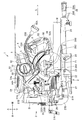
- 1 is a block diagram of a tabletop cutting machine according to a first embodiment of the present invention.
- a tabletop cutting machine 1 which is an example of the cutting machine shown in FIG. 1 is mainly configured by a base part 2, a support part 3 connected to the base part 2, and a cutting part 4 supported by the support part 3.
- the cutting unit 4 includes a housing 5, a motor 6 having a motor output shaft 61 (FIG. 7), an output shaft 7 driven by the motor 6, a cutting blade 8 detachably attached to the output shaft 7, a battery A battery pack attaching / detaching portion 10 (FIG. 2) to which the pack 9 is detachably attached.
- the support part 3 is an example of the swing support mechanism of the present invention.
- the motor output shaft 61 is an example of the rotating shaft of the present invention.
- the side where the cutting portion 4 is provided with respect to the base portion 2 is defined as the upward direction, and the opposite is defined as the downward direction.
- the right side in FIG. 1 is defined as the front, and the reverse is defined as the rear.
- the left and right directions viewed from the front are defined as a right direction and a left direction, respectively.
- a direction such as an upward direction, it includes not only a complete upward direction but also a substantially upward direction.
- the cutting portion 4 can swing (as an axis) around a swing shaft 35A (a shaft extending in the left-right direction), which will be described later, parallel to the output shaft 7 with respect to the base portion 2. Specifically, the cutting portion 4 swings between a separation position where the cutting blade 8 and the base portion 2 shown in FIG. 1 are most separated from each other and a proximity position where the cutting blade 8 shown in FIG. Is possible.
- the separation position is an example of the top dead center of the present invention
- the proximity position is an example of the bottom dead center of the present invention.
- the cutting part 4 can tilt with respect to the base part 2 around a tilting shaft part 27A (an axis extending in the front-rear direction), which will be described later, orthogonal to the output shaft 7. As shown in FIG. 2, the cutting portion 4 can tilt in a clockwise direction R and a counterclockwise direction L described later with respect to the base portion 2 when viewed from the front. As shown in FIG. 1, the cutting part 4 is movable in the sliding direction S (front-rear direction) with respect to the base part 2. A detailed configuration will be described later.
- the base unit 2 includes a base 21, a turntable 22 disposed on the base 21, a fence 23 provided on the base 21, and a vice device 26 for fixing the wood W.
- the upper surfaces of the base 21 and the turntable 22 form a contact surface 25 on which the wood W is placed.
- the base 21 includes a pair of a left base 21A and a right base 21B.
- the turntable 22 is rotatable about a rotation shaft (not shown) extending in the vertical direction with respect to the base 21, and between the right base 21B and the left base 21A.
- the turntable 22 includes a substantially circular turntable main body portion 22A, a protruding portion 24 protruding forward from the turntable main body portion 22A, and a housing support portion 27 that supports the support portion 3.
- a groove (not shown) is formed on the upper surface of the turntable 22. The groove portion (not shown) is located at the same position as the line of intersection when the cutting blade 8 swings downward and crosses the turntable 22 in a side view, and the cutting edge of the cutting blade 8 is accommodated and passes therethrough.
- the protruding portion 24 is provided with a regulating operation portion 28 that regulates the rotation of the turntable 22 relative to the base 21.
- the restricting operation portion 28 is supported by the protruding portion 24, and can be gripped by the operator, and extends forward from the protruding portion 24.
- the restricting operating portion 28 is screwed and retracted by a rotation operation of the holding portion 28A.
- a regulating portion 28 ⁇ / b> B having a rear end surface that can move in the front-rear direction within 24 and can come into contact with and be separated from the base 21.
- the vice device 26 includes a vise shaft 26A extending in the vertical direction, a screw holder 26B, and a knob 26C.
- a screw holder 26B is provided on the vise shaft 26A so as to be movable in the vertical direction, and the distance from the contact surface 25 can be adjusted according to the size of the wood W.
- the wood W can be fixed by the vice device 26 by operating the knob 26C.
- the housing support portion 27 is disposed at a position opposite to the protruding portion 24 with respect to a rotation shaft (not shown) of the turntable 22 (a position rotated 180 ° around a rotation shaft (not shown)). . That is, it is arranged behind the turntable 22.
- the housing support portion 27 includes a tilt shaft portion 27A that is located on an extension line of a groove portion (not shown) of the turntable 22 and extends in the front-rear direction, and a tilt support portion 27B that stands upright from the rear end portion. .
- the housing support portion 27 is an example of the tilt angle adjusting mechanism of the present invention.
- the tilting support portion 27B is formed with an arc-shaped long hole 27b penetrating in the front-rear direction and centering on the tilting shaft portion 27A.
- a clamp 31A described later is inserted into the long hole 27b.
- a set pin 29 serving as a positioning member at a right angle is attached to the tilting support portion 27B so that it can be pulled out in the front-rear direction.
- the cutting portion 4 can tilt only in the counterclockwise direction L when the set pin 29 is inserted, and can tilt in the clockwise direction R and the counterclockwise direction L when the set pin 29 is pulled out. is there.
- the tilt shaft portion 27A is an example of the tilt shaft of the present invention.
- the fence 23 is provided on the base 21 and above the turntable 22. As shown in FIG. 2, the fence 23 has a left fence 23A and a right fence 23B corresponding to the left base 21A and the right base 21B, and the front surfaces of the left fence 23A and the right fence 23B are located on the same plane.
- the wood W (FIG. 1) is positioned.
- the support portion 3 includes a holder 31, a slide support portion 33, a swing support portion 35, and a slide portion 36.
- the holder 31 is supported by the housing support portion 27 via the tilt shaft portion 27A.
- a clamp 31A is screwed into the holder 31, and the clamp 31A is inserted into a long hole 27b (FIG. 2) of the tilt support portion 27B.
- the holder 31 is fixed to the tilting support portion 27B. That is, the cutting part 4 cannot be tilted in the counterclockwise direction L and the clockwise direction R shown in FIG.
- the clamp 31A By loosening the clamp 31A, the holder 31 can tilt about the tilting shaft portion 27A.
- the cutting part 4 can tilt in the counterclockwise direction L and the clockwise direction R shown in FIG. Since the clamp 31A is inserted into the long hole 27b, the angle at which the holder 31 can be tilted with respect to the tilt support portion 27B is limited to a range in which the clamp 31A can move within the long hole 27b.
- the slide support portion 33 has two guide bars 33A and 33B.
- Each of the guide bars 33A and 33B has a substantially identical pipe shape, is parallel to the upper surface (contact surface 25) of the base portion 2 in parallel in the vertical direction, and the respective axial directions coincide with the front-rear direction. It is fixed to the holder 31. Specifically, these guide bars 33A and 33B are fixed to the holder 31 so as not to be detachable by bolts (not shown) screwed to the holder 31, respectively.
- the slide support portion 33 is an example of a slide support mechanism of the present invention.
- the guide bars 33A and 33B are examples of slide pipes.
- a connecting member 33C is provided at the front end of the guide bars 33A and 33B.
- the guide bars 33A and 33B are connected to each other by the connecting member 33C.
- two holes extending in the front-rear direction are formed in the connecting member 33C, and the front end portions of the guide bars 33A and 33B are inserted and fixed in the holes, respectively.
- the swing support portion 35 includes a swing shaft 35A extending in the left-right direction and a pair of swing wall portions 35B extending in the vertical direction when viewed from the back, and is configured to move integrally with the slide portion 36.
- the swing shaft 35A is installed between the pair of swing wall portions 35B and pivotally supports the cutting portion 4 so as to be swingable.
- a spring (not shown) is attached to the swing support portion 35 and biases the cutting portion 4 in a direction from the proximity position toward the separation position.
- the slide portion 36 is formed with two through holes extending in the front-rear direction, and guide bars 33A and 33B are inserted into the through holes, respectively.
- the swing support portion 35 can move in the slide direction S (front-rear direction). That is, the cutting part 4 can move in the sliding direction S along the guide bars 33A and 33B.
- An operation knob 36 ⁇ / b> A that can be screwed to protrude into the slide portion 36 is screwed to the slide portion 36. By sliding the operation knob 36A and pressing the guide bar 33A against the slide part 36, the slide part 36 can be fixed to the guide bars 33A and 33B.
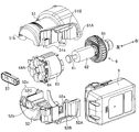
- the housing 5 includes a motor housing 50, a work handle 53, a transport handle 54, a gear accommodating portion 55, and a saw cover 56.
- the motor housing 50 accommodates the motor 6 (FIG. 7) therein, and is provided with a battery pack attaching / detaching portion 10, a display portion 57, and a connection terminal 58 electrically connected to the battery pack 9.
- the display unit 57 includes a switch 57A for switching to a silent mode in which the rotational speed of the motor 6 is controlled at low speed, and the battery pack 9 in order to suppress the driving sound of the tabletop cutting machine 1 and the consumption of the battery pack 9. And a remaining battery level display switch 57B for displaying the remaining battery level.
- the display unit 57 is disposed on the left end surface of the motor housing 50.
- FIG. 3 FIG. 4, FIG. 7, FIG. 8, FIG. 10, and FIG. 12, the display of the changeover switch 57A and the battery remaining amount display switch 57B is omitted. 7 and 8, the display of the connection terminal 58 is omitted.
- the motor housing 50 is a split type (divided into two) housings composed of a first motor housing 51 and a second motor housing 52.
- the 1st motor housing 51 and the 2nd motor housing 52 are examples of the division piece of the present invention.
- the first motor housing 51 includes a first mating surface 51A that contacts the second motor housing 52, a first rail portion 51B that can be engaged with the battery pack 9, and a plurality of first screw hole portions 51C. Yes.
- the first motor housing 51 is formed with a first electrode groove 51a and a first display groove 51b.
- the first rail portion 51 ⁇ / b> B extends in parallel with the motor output shaft 61 and protrudes toward the second motor housing 52.
- the first electrode groove 51 a and the first display groove 51 b are formed so as to be recessed in a direction orthogonal to the motor output shaft 61.
- the plurality of first screw hole portions 51 ⁇ / b> C has a boss shape projecting from the first mating surface 51 ⁇ / b> A, is formed with a female screw, and is formed in a direction orthogonal to the motor output shaft 61.
- the second motor housing 52 includes a second mating surface 52A that contacts the first mating surface 51A, a second rail portion 52B that can be engaged with the battery pack 9, and a wall portion 52C.
- a second electrode groove 52a, a second display groove 52b, and a plurality of second screw holes 52c are formed in the second motor housing 52.
- the first mating surface 51A and the second mating surface 52A are in contact with each other on a plane extending in parallel with the motor output shaft 61. That is, when viewed from the direction orthogonal to the motor output shaft 61, the first mating surface 51A, the second mating surface 52A, and the motor output shaft 61 are parallel.
- the motor output shaft 61 is positioned on a plane including the first mating surface 51A and the second mating surface 52A.
- the second rail portion 52 ⁇ / b> B extends in parallel with the motor output shaft 61 and protrudes toward the first motor housing 51.
- the first mating surface 51A and the second mating surface 52A are examples of the mating surface of the present invention.
- the first rail part 51B and the second rail part 52B are examples of the rail part of the present invention.
- the wall portion 52C supports the motor output shaft 61 to be rotatable.
- the first motor housing 51 is also provided with a wall portion (not shown), and a space in which the motor 6 is accommodated is defined by the contact of the wall portion (not shown) and the wall portion 52C.
- the second electrode groove 52 a and the second display groove 52 b are formed so as to be recessed in a direction orthogonal to the motor output shaft 61.
- the first motor housing 51 and the second motor housing 52 When the first motor housing 51 and the second motor housing 52 are coupled, the first rail portion 51B and the second rail portion 52B extend in parallel with the motor output shaft 61, and the battery pack attaching / detaching portion 10 is formed in the motor housing 50.
- the first motor housing 51 and the second motor housing 52 are fixed to each other by screwing with a female screw of the first screw hole 51C through a second screw hole 52c corresponding to a screw (not shown). .
- a screw (not shown) is inserted from the second motor housing 52 side toward the first motor housing 51 side.
- the first screw hole 51C and the second screw hole 52c open substantially downward, so that dust or the like can be prevented from accumulating in the respective holes.
- the battery pack attaching / detaching portion 10 and the motor 6 are arranged in a direction perpendicular to the output shaft 7 with respect to the output shaft 7.
- the battery pack 9, the battery pack attaching / detaching portion 10, and the motor 6 are positioned radially outward of the cutting blade 8.
- the battery pack 9 can be attached to and detached from the battery pack attaching / detaching part 10 along the direction (attaching / detaching direction D) in which the first rail part 51B and the second rail part 52B extend.
- the extending direction of the first rail part 51B and the second rail part 52B, that is, the attaching / detaching direction D is the left-right direction.
- the attachment / detachment direction D is orthogonal to the slide direction S of the cutting part 4 in a front view.
- the battery pack 9 is inserted in the right direction when viewed from the front.
- the mounting direction (right direction) of the battery pack 9 is substantially opposite to the tilting direction of the cutting part 4.
- the battery pack attaching / detaching portion 10 is located at the front portion of the motor housing 50 when the cutting portion 4 is in the close position. As shown in FIGS. 3, 4, and 5, the left end portion of the motor housing 50 is located on the right side of the left end portion of the battery pack 9 attached to the battery pack attaching / detaching portion 10. In other words, the length of the battery pack 9 in the longitudinal direction is longer than the lengths of the motor 6 and the motor housing 50 in the longitudinal direction.
- the work handle 53 is provided in front of the battery pack attaching / detaching portion 10 and the motor housing 50, and is located above the cutting blade 8 when the cutting portion 4 is in the separated position.
- the work handle 53 is substantially D-shaped when viewed from the side, and is provided with a switch trigger 53A for controlling on / off of the motor 6. The operator can hold the work handle 53 and move the cutting unit 4 from the separated position to the close position.
- the transport handle 54 is provided behind the work handle 53 and behind the motor housing 50.
- the work handle 53 and the transport handle 54 are arranged side by side in a direction (substantially front-rear direction) parallel to the side surface of the cutting blade 8 in a side view.
- the motor 6, the battery pack attaching / detaching portion 10, and the battery pack 9 are arranged between the work handle 53 and the transport handle 54.
- “Between the work handle 53 and the transport handle 54” means that when the work handle 53 and the transport handle 54 are connected in a band shape in a side view, at least a part of the band overlaps.
- the transport handle 54 is substantially horizontal when the cutting portion 4 is in the close position, and is used for transporting the tabletop cutting machine 1 with the cutting portion 4 fixed at the close position by a lock pin (not shown). This makes it easier for the operator to grip.
- the transport handle 54 includes a transport grip portion 54 ⁇ / b> A that is gripped when an operator transports the tabletop cutting machine 1. As shown by a two-dot chain line in FIG. 6, the upper end portion of the carrying grip portion 54 ⁇ / b> A is located above the battery pack 9 attached to the battery pack attaching / detaching portion 10. Thereby, the size in the vertical direction is suppressed during transportation, and transportation in a compact state becomes possible.
- a gripping hole 54a is formed in the carrying handle 54, and the gripping hole 54a extends substantially in the front-rear direction when the cutting portion 4 is in the close position.
- the gear housing 55 is located on the right side of the motor housing 50. As shown in FIG. 1, the gear housing portion 55 is located at a position overlapping the motor housing 50 in a side view, and is located between the work handle 53 and the transport handle 54.
- the gear housing 55 is composed of a plurality of gears, and houses a driving force transmission mechanism (not shown) that transmits driving force from the motor 6 to the cutting blade 8.
- the gear housing 55 is provided with an LED 55A for illumination that extends forward and is supported by the flexible support 55B. The operator can irradiate the LED 55A to a desired place by operating the flexible support portion 55B.
- the saw cover 56 is provided on the left side surface of the gear housing portion 55 and covers the upper half of the cutting blade 8.
- a saw cover 56 ⁇ / b> A covering the lower outer periphery of the cutting blade 8 exposed from the saw cover 56 is provided in the saw cover 56 so as to be rotatable about the output shaft 7.
- the saw cover 56 ⁇ / b> A covers the outer periphery of the cutting blade 8 exposed from the saw cover 56 when the cutting portion 4 is in the separated position.
- the saw cover 56 ⁇ / b> A is rotated around the output shaft 7 by a link mechanism (not shown) and stored in the saw cover 56 when the cutting portion 4 is in the close position, and the lower half of the cutting blade 8. Is exposed from the saw cover 56.
- the motor 6 is a brushless motor, and as shown in FIG. 7, a motor output shaft 61, a rotor 62 fixed to the motor output shaft 61, and a stator 63 facing the rotor 62 in the radial direction of the motor output shaft 61
- the inverter circuit 64 is fixed to the left end of the stator 63
- the cooling fan 65 is fixed to the motor output shaft 61.
- the motor output shaft 61 extends in the left-right direction.
- the right end portion of the motor output shaft 61 is engaged with a driving force transmission mechanism (not shown) housed in the gear housing portion 55, and the left end portion of the motor output shaft 61 is rotatably supported on the wall portion 52C.
- the rotor 62 includes two sets of magnets, and the stator 63 includes a coil facing the magnets.
- the inverter circuit 64 includes six switching elements 64 ⁇ / b> A for controlling driving of the motor 6 and a magnetic sensor 15 for detecting the position of the stator 63.
- the magnetic sensor 15 is a Hall element, for example, and faces the rotor 62 in the left-right direction.
- the inverter circuit 64 is provided at the left end portion of the stator 63.
- the stator 63 and the inverter circuit 64 are arranged so as to fit in the entire length of the battery pack 9.
- the battery pack 9 (battery pack attaching / detaching portion 10), the stator 63, and the inverter circuit 64 overlap each other when viewed from the direction orthogonal to the motor output shaft 61 and passing through the battery pack attaching / detaching portion 10.
- the cutting unit 4 is provided with a control circuit board (not shown) having the control unit 11 (FIG. 9).
- the control unit 11 performs drive control of the inverter circuit 64 and control of the LED 55A.
- the inverter circuit 64 is electrically connected to the motor 6, the control unit 11, and the battery pack 9.
- a detection resistor 12 for current detection and a capacitor 13 connected in parallel with the battery pack 9 are provided.
- the control unit 11 includes a control power supply circuit 14, a current detection circuit 16, a switch operation detection circuit 17, a voltage detection circuit 18, a rotation position detection circuit 19, a rotation number detection circuit 20, a calculation unit 41, a control And a signal circuit 42.
- the control power supply circuit 14 converts the voltage of the battery pack 9 into a voltage suitable for the operation of the control unit 11 and supplies it to the control unit 11.
- the current detection circuit 16 detects the drive current of the motor 6 based on the terminal voltage of the detection resistor 12.
- the switch operation detection circuit 17 detects the operation amount of the switch trigger 53A by the operator.
- the voltage detection circuit 18 detects the drive voltage of the motor 6 by the capacitor 13.
- the rotational position detection circuit 19 detects the rotational position of the motor 6 based on the signal from the magnetic sensor 15.
- the rotation speed detection circuit 20 detects the rotation speed of the motor 6 based on the signal from the rotation position detection circuit 19.
- the computing unit 41 is based on the signal from the switch operation detection circuit 17 and according to the operation amount of the switch trigger 53A, the duty ratio of the PWM signal applied to each switching element 64A of the inverter circuit 64 (hereinafter referred to as the duty ratio). ) Is set.
- the calculation unit 41 drives the control signal circuit 42 according to the set duty ratio and the rotational position of the motor 6 detected by the rotational position detection circuit 19, and performs switching control of each switching element 64 ⁇ / b> A of the inverter circuit 64.
- the calculation unit 41 calculates the rotation speed of the motor 6 based on the detection result of the rotation position detection circuit 19, and based on the detection result of the rotation position detection circuit 19 based on the set reduction ratio between the motor 6 and the cutting blade 8. The rotational speed of the cutting blade 8 is detected.
- a laser drive circuit 43 and an illumination LED drive circuit 44 are connected to the control unit 11.
- the laser drive circuit 43 is connected to the laser 43A and irradiates the laser 43A based on the operation of the laser switch 43B. The operator can cut the wood W with reference to the laser beam irradiated by the laser 43A.
- the illumination LED drive circuit 44 is connected to the LED 55A, and turns on the illumination LED 55A based on the operation of the LED switch 44A.
- the operator attaches the battery pack 9 to the battery pack attaching / detaching portion 10 along the attaching / detaching direction D.
- the switch trigger 53A is pulled to drive the motor 6 to rotate the cutting blade 8, and the work handle 53 is pushed downward to move the cutting portion 4 downward.
- the cutting part 4 is moved downward by swinging the cutting part 4 in the clockwise direction in the left side view with the swing support part 35 as the center (axis).
- the cutting blade 8 and the wood W are brought into contact with each other to start cutting, and the cutting portion 4 is slid with respect to the slide support portion 33 (guide bars 33A and 33B) to move the cutting portion 4 rearward. Disconnect.
- both side surfaces of the cutting blade 8 are inclined with respect to the contact surface 25.
- the cutting portion 4 is tilted in the clockwise direction R of FIG. 2, the set pin 29 is completely retracted from the holder 31 and the clamp 31A is loosened. Alternatively, the set pin 29 may be retracted from the holder 31 after the clamp 31A is loosened. Thereby, the support part 3 and the cutting part 4 can be tilted in the counterclockwise direction L and the clockwise direction R with respect to the base part 2.
- the cutting portion 4 inclined in either the counterclockwise direction L or the clockwise direction R has its maximum inclination angle determined by the holder 31 coming into contact with a stopper bolt (not shown). In order to set the maximum inclination angle to 45 °, a stopper bolt (not shown) is adjusted so that the holder 31 is in contact with the holder 31 while being inclined at 45 °. *
- the attachment / detachment direction D (FIG. 2) of the battery pack 9 is the swinging direction of the cutting unit 4, That is, it becomes a direction intersecting (orthogonal) with the side surface of the cutting blade 8, and the cutting portion 4 is not easily swung by the attaching / detaching operation of the battery pack 9, so that the attaching / detaching operation can be easily performed. Moreover, it can suppress that the cutting
- the battery pack attaching / detaching portion 10 can be provided in the motor housing 50, there is no need to separately prepare a housing constituting the battery pack attaching / detaching portion 10, and the number of parts can be reduced and the cutting portion can be reduced. Miniaturization can be achieved. Therefore, the battery pack attaching / detaching portion 10 can be manufactured and assembled with a simple configuration. Further, when wiring a lead wire or the like from the battery pack attaching / detaching portion 10 to the motor 6, it is possible to wire without passing through another housing, so that the structure can be simplified and the assembly is also easy.
- the first rail portion 51B is provided in the first motor housing 51, and the second rail portion 52B is provided in the second motor housing 52.
- the battery pack can be manufactured without being divided in the attaching / detaching direction. Thereby, the precision of a rail part is ensured and the battery pack 9 can be smoothly attached or detached.
- connection terminal 58 is assembled so as to be sandwiched between the first motor housing 51 and the second motor housing 52, a metal fitting for attaching the connection terminal 58 to the motor housing 50 is unnecessary. is there. Thereby, the motor housing 50 can be easily assembled while the connection terminal 58 is securely held.
- the display unit 57 is assembled so as to be sandwiched between the first motor housing 51 and the second motor housing 52, so that metal fittings for attaching these components to the motor housing 50 are not necessary. is there. Thereby, the motor housing 50 can be easily assembled while the display portion 57 is securely held.
- the protrusion edge part of the motor housing 50 is arrange
- the battery pack attaching / detaching portion 10 is provided between the transport handle 54 and the work handle 53, the distance from the battery pack attaching / detaching portion 10 to both the handles is shortened. At the time of holding 9, it becomes easy to grasp one of the handles to stabilize the cutting portion 4.
- the attachment / detachment direction D of the battery pack 9 is orthogonal to the sliding direction S of the cutting part 4. Therefore, it is difficult for the cutting portion 4 to slide by the battery pack 9 attaching / detaching operation, and the attaching / detaching operation of the battery pack 9 can be easily performed. In addition, damage to the wood W placed on the base 21 can be suppressed.
- the motor 6, the connection terminal 58, the inverter circuit 64, and the display unit 57 are accommodated in the longitudinal (left / right) dimension of the battery pack 9, the left / right dimension (full width) of the cutting unit 4. It can be set as the small desk-top cutting machine 1 which suppressed this.
- the configuration unique to the DC-driven tabletop cutting machine 1 such as the battery pack 9, the inverter circuit 64, and the display unit 57 is concentrated in the motor housing 50. It can be shared with the cutting machine driven by Thereby, the manufacturing cost of the tabletop cutting machine 1 can be reduced.
- the attachment / detachment direction D of the battery pack 9 is a direction orthogonal to the side surface of the cutting blade 8, but may be a direction in which the attachment / detachment direction D and the side surface of the cutting blade 8 intersect.
- Second Embodiment A second embodiment which is a modification of the present invention will be described with reference to FIGS.
- the same configurations as those of the first embodiment are denoted by the same reference numerals and description thereof is omitted.
- the attachment / detachment direction D of the battery pack 9 is different from that of the first embodiment.
- the motor housing 150 includes a first motor housing 151 and a second motor housing 152. When both are fixed to each other, a battery pack attaching / detaching portion 110 is formed. A connection terminal 158 is provided on the motor housing 150. As shown in FIG. 11, the motor housing 150 extends obliquely in the upper left direction when viewed from the front. Further, as shown in FIG. 10, when the cutting portion 4 is in the separated position, the motor housing 150 is inclined in the front-rear direction and also in the vertical direction. As shown in FIG. 12, when the cutting part 4 is in the proximity position, it is inclined in the vertical direction. As in the first embodiment, the motor housing 150, the motor output shaft 61, the first rail portion 51B, and the second rail portion 52B all extend in the same direction.
- the attachment / detachment direction D2 of the battery pack 9 is an obliquely upper left direction in a front view.
- the attachment / detachment direction D2 is a direction that intersects the side surface (vertical surface extending in the vertical direction) of the cutting blade 8, and when the cutting portion 4 is in the close position (state of FIG. 11), it is obliquely upper left and oblique in the front view. It is the direction connecting the lower right.
- the attachment / detachment direction D intersects the slide direction S when the cutting part 4 is in the separation position. As shown in FIGS.
- the attachment / detachment direction D is orthogonal to the slide direction S when the cutting portion 4 is in the close position. That is, when the cutting part 4 is in the close position, the attaching / detaching direction D and the sliding direction S are substantially orthogonal in a plan view.
- the cutting machine by this invention is not limited to the above-mentioned embodiment, For example, a various change is possible within the range of the summary of the invention described in the claim.
- the tabletop cutting machine 1 is used as a cutting machine, but it can also be used for a portable cutting machine.
- the motor housing 50 includes the first mating surface 51A and the second mating surface 52A extending parallel to the axial direction of the motor output shaft 61 of the motor 6 when viewed from the direction orthogonal to the motor output shaft 61.
- the split housing which has, it is not limited to this.
- an integrally molded motor housing may be used, or a split type (divided into two) housings having a mating surface orthogonal to the axial direction of the motor output shaft may be used.
- the motor housing 50 is constituted by the two-split housing of the first motor housing 51 and the second motor housing 52, but is not limited to this. You may be comprised with the housing divided
- the battery pack attaching / detaching portion 10 is provided in front of the motor housing 50 when the cutting portion 4 is in the close position (FIG. 6), but is not limited thereto.
- the battery pack attaching / detaching portion may be disposed behind the motor housing 50.
- the battery pack attaching / detaching portion may be disposed on either one of the first motor housing and the second motor housing.
- the motor 6 is a brushless motor, but a brush motor may be used.
- the battery pack attaching / detaching portion 10 is provided in the motor housing 50.
- the present invention is not limited to this. If it is on the housing 5 of the cutting part 4, it can be provided at an arbitrary position on condition that the attaching / detaching direction D of the battery pack 9 is a direction intersecting the side surface of the cutting blade 8.
- it may be provided on the work handle 53, the transport handle 54, or the like, or may be provided on the gear housing 55.
- the attachment / detachment direction of the battery pack 9 is not limited to the above-described embodiment, and may be another direction as long as it intersects the side surface of the cutting blade 8.
- the slide-type or tiltable tabletop cutting machine 1 is used.
- the present invention is not limited to this, and the present invention can be applied to a cutting machine that does not use or does not tilt.
- the structure is not limited to the structure in which the cutting portion 4 slides on the guide bars 33A and 33B, but may be a structure that slides together with the cutting portion 4 and the guide bars 33A and 33B.
Landscapes
- Engineering & Computer Science (AREA)
- Mechanical Engineering (AREA)
- Life Sciences & Earth Sciences (AREA)
- Wood Science & Technology (AREA)
- Forests & Forestry (AREA)
- Sawing (AREA)
Abstract
Priority Applications (6)
| Application Number | Priority Date | Filing Date | Title |
|---|---|---|---|
| EP16802973.4A EP3305487B1 (fr) | 2015-05-29 | 2016-04-29 | Machine de coupe |
| US15/577,628 US10286462B2 (en) | 2015-05-29 | 2016-04-29 | Cutting machine |
| JP2017521751A JP6284071B2 (ja) | 2015-05-29 | 2016-04-29 | 切断機 |
| CN201680033202.3A CN107635734B (zh) | 2015-05-29 | 2016-04-29 | 切割机 |
| EP21184295.0A EP3912776B1 (fr) | 2015-05-29 | 2016-04-29 | Machine à découper |
| US16/408,082 US10888938B2 (en) | 2015-05-29 | 2019-05-09 | Cutting machine |
Applications Claiming Priority (2)
| Application Number | Priority Date | Filing Date | Title |
|---|---|---|---|
| JP2015-109864 | 2015-05-29 | ||
| JP2015109864 | 2015-05-29 |
Related Child Applications (2)
| Application Number | Title | Priority Date | Filing Date |
|---|---|---|---|
| US15/577,628 A-371-Of-International US10286462B2 (en) | 2015-05-29 | 2016-04-29 | Cutting machine |
| US16/408,082 Continuation US10888938B2 (en) | 2015-05-29 | 2019-05-09 | Cutting machine |
Publications (1)
| Publication Number | Publication Date |
|---|---|
| WO2016194536A1 true WO2016194536A1 (fr) | 2016-12-08 |
Family
ID=57440015
Family Applications (1)
| Application Number | Title | Priority Date | Filing Date |
|---|---|---|---|
| PCT/JP2016/063519 WO2016194536A1 (fr) | 2015-05-29 | 2016-04-29 | Machine de coupe |
Country Status (5)
| Country | Link |
|---|---|
| US (2) | US10286462B2 (fr) |
| EP (2) | EP3305487B1 (fr) |
| JP (1) | JP6284071B2 (fr) |
| CN (1) | CN107635734B (fr) |
| WO (1) | WO2016194536A1 (fr) |
Cited By (8)
| Publication number | Priority date | Publication date | Assignee | Title |
|---|---|---|---|---|
| JP2018065222A (ja) * | 2016-10-20 | 2018-04-26 | マックス株式会社 | 携帯用切断機 |
| JP2018089867A (ja) * | 2016-12-05 | 2018-06-14 | 株式会社マキタ | 切断機 |
| WO2019111632A1 (fr) * | 2017-12-06 | 2019-06-13 | 株式会社マキタ | Machine à scier fixe pour travail du métal |
| CN113227498A (zh) * | 2019-01-11 | 2021-08-06 | 罗贝尔铁路建筑机械有限责任公司 | 切割式打磨机和用于切穿轨道的铁轨的方法 |
| WO2021166392A1 (fr) * | 2020-02-17 | 2021-08-26 | 株式会社マキタ | Machine de travail |
| JP2021171886A (ja) * | 2020-04-28 | 2021-11-01 | 工機ホールディングス株式会社 | バンドソー |
| WO2022254907A1 (fr) * | 2021-06-04 | 2022-12-08 | 工機ホールディングス株式会社 | Machine de travail |
| EP3275582B1 (fr) * | 2016-07-27 | 2024-10-16 | Techtronic Cordless GP | Scie à onglet |
Families Citing this family (7)
| Publication number | Priority date | Publication date | Assignee | Title |
|---|---|---|---|---|
| JP6284071B2 (ja) | 2015-05-29 | 2018-02-28 | 日立工機株式会社 | 切断機 |
| CN112384331B (zh) * | 2018-09-28 | 2023-12-26 | 工机控股株式会社 | 作业机 |
| JP7118862B2 (ja) * | 2018-10-30 | 2022-08-16 | 株式会社マキタ | 切断機 |
| DE102018222159A1 (de) * | 2018-12-18 | 2020-06-18 | Robert Bosch Gmbh | Werkzeugmaschine |
| CN112223433A (zh) * | 2019-07-15 | 2021-01-15 | 株式会社牧田 | 自动刨床 |
| US20220168828A1 (en) * | 2020-12-02 | 2022-06-02 | Makita Corporation | Sliding cutting machine |
| CN217452379U (zh) * | 2022-05-10 | 2022-09-20 | 南京泉峰科技有限公司 | 台型切割装置 |
Citations (4)
| Publication number | Priority date | Publication date | Assignee | Title |
|---|---|---|---|---|
| WO2012108415A1 (fr) * | 2011-02-10 | 2012-08-16 | 株式会社マキタ | Outil électrique |
| JP2014079812A (ja) * | 2011-10-20 | 2014-05-08 | Makita Corp | 切断機 |
| JP2014144508A (ja) * | 2013-01-29 | 2014-08-14 | Hitachi Koki Co Ltd | 卓上切断機 |
| JP2014148015A (ja) * | 2013-02-01 | 2014-08-21 | Makita Corp | 充電式切断工具 |
Family Cites Families (14)
| Publication number | Priority date | Publication date | Assignee | Title |
|---|---|---|---|---|
| JP3558880B2 (ja) * | 1998-07-09 | 2004-08-25 | 株式会社マキタ | 卓上マルノコ盤 |
| JP2000308268A (ja) * | 1999-04-15 | 2000-11-02 | Makita Corp | 充電式電動工具 |
| CN201271763Y (zh) | 2008-09-26 | 2009-07-15 | 王伟鹏 | 一种改进的切割机 |
| US8302519B2 (en) | 2008-12-31 | 2012-11-06 | Techtronic Power Tools Technology Limited | Hand-held power tool |
| US20110284257A1 (en) * | 2009-02-10 | 2011-11-24 | Makita Corporation | Electric tool |
| JP5410843B2 (ja) * | 2009-06-02 | 2014-02-05 | 株式会社マキタ | 切断機 |
| JP2011099349A (ja) * | 2009-11-04 | 2011-05-19 | Denso Corp | アルコールセンサ異常診断装置 |
| JP5432761B2 (ja) * | 2010-02-12 | 2014-03-05 | 株式会社マキタ | 複数のバッテリパックを電源とする電動工具 |
| JP5461221B2 (ja) * | 2010-02-12 | 2014-04-02 | 株式会社マキタ | 複数のバッテリパックを電源とする電動工具 |
| US20150328796A1 (en) | 2013-02-01 | 2015-11-19 | Makita Corporation | Cutting device |
| JP6100004B2 (ja) | 2013-02-01 | 2017-03-22 | 株式会社マキタ | 卓上切断機 |
| JP6284071B2 (ja) | 2015-05-29 | 2018-02-28 | 日立工機株式会社 | 切断機 |
| CN208866497U (zh) * | 2018-08-23 | 2019-05-17 | 创科(澳门离岸商业服务)有限公司 | 切入式圆锯 |
| DE102018215308A1 (de) * | 2018-09-10 | 2020-03-12 | Robert Bosch Gmbh | Staubsaugvorrichtung |
-
2016
- 2016-04-29 JP JP2017521751A patent/JP6284071B2/ja active Active
- 2016-04-29 EP EP16802973.4A patent/EP3305487B1/fr active Active
- 2016-04-29 CN CN201680033202.3A patent/CN107635734B/zh active Active
- 2016-04-29 US US15/577,628 patent/US10286462B2/en active Active
- 2016-04-29 WO PCT/JP2016/063519 patent/WO2016194536A1/fr active Application Filing
- 2016-04-29 EP EP21184295.0A patent/EP3912776B1/fr active Active
-
2019
- 2019-05-09 US US16/408,082 patent/US10888938B2/en active Active
Patent Citations (4)
| Publication number | Priority date | Publication date | Assignee | Title |
|---|---|---|---|---|
| WO2012108415A1 (fr) * | 2011-02-10 | 2012-08-16 | 株式会社マキタ | Outil électrique |
| JP2014079812A (ja) * | 2011-10-20 | 2014-05-08 | Makita Corp | 切断機 |
| JP2014144508A (ja) * | 2013-01-29 | 2014-08-14 | Hitachi Koki Co Ltd | 卓上切断機 |
| JP2014148015A (ja) * | 2013-02-01 | 2014-08-21 | Makita Corp | 充電式切断工具 |
Non-Patent Citations (1)
| Title |
|---|
| See also references of EP3305487A4 * |
Cited By (13)
| Publication number | Priority date | Publication date | Assignee | Title |
|---|---|---|---|---|
| EP3275582B1 (fr) * | 2016-07-27 | 2024-10-16 | Techtronic Cordless GP | Scie à onglet |
| JP2018065222A (ja) * | 2016-10-20 | 2018-04-26 | マックス株式会社 | 携帯用切断機 |
| JP2018089867A (ja) * | 2016-12-05 | 2018-06-14 | 株式会社マキタ | 切断機 |
| WO2018105494A1 (fr) * | 2016-12-05 | 2018-06-14 | 株式会社マキタ | Machine de coupe |
| US11027344B2 (en) | 2016-12-05 | 2021-06-08 | Makita Corporation | Cutting device |
| WO2019111632A1 (fr) * | 2017-12-06 | 2019-06-13 | 株式会社マキタ | Machine à scier fixe pour travail du métal |
| CN113227498B (zh) * | 2019-01-11 | 2023-07-18 | 罗贝尔铁路建筑机械有限责任公司 | 切割式打磨机和用于切穿轨道的铁轨的方法 |
| CN113227498A (zh) * | 2019-01-11 | 2021-08-06 | 罗贝尔铁路建筑机械有限责任公司 | 切割式打磨机和用于切穿轨道的铁轨的方法 |
| WO2021166392A1 (fr) * | 2020-02-17 | 2021-08-26 | 株式会社マキタ | Machine de travail |
| US11938607B2 (en) | 2020-02-17 | 2024-03-26 | Makita Corporation | Power tool with light emitter |
| JP7495793B2 (ja) | 2020-02-17 | 2024-06-05 | 株式会社マキタ | 作業機 |
| JP2021171886A (ja) * | 2020-04-28 | 2021-11-01 | 工機ホールディングス株式会社 | バンドソー |
| WO2022254907A1 (fr) * | 2021-06-04 | 2022-12-08 | 工機ホールディングス株式会社 | Machine de travail |
Also Published As
| Publication number | Publication date |
|---|---|
| EP3912776B1 (fr) | 2023-11-22 |
| EP3305487A4 (fr) | 2019-01-02 |
| US10888938B2 (en) | 2021-01-12 |
| JPWO2016194536A1 (ja) | 2018-02-22 |
| US20190262916A1 (en) | 2019-08-29 |
| EP3912776A1 (fr) | 2021-11-24 |
| EP3305487A1 (fr) | 2018-04-11 |
| CN107635734A (zh) | 2018-01-26 |
| CN107635734B (zh) | 2019-01-01 |
| EP3305487B1 (fr) | 2021-12-08 |
| US10286462B2 (en) | 2019-05-14 |
| JP6284071B2 (ja) | 2018-02-28 |
| US20180161891A1 (en) | 2018-06-14 |
Similar Documents
| Publication | Publication Date | Title |
|---|---|---|
| JP6284071B2 (ja) | 切断機 | |
| JP6100004B2 (ja) | 卓上切断機 | |
| US10589412B2 (en) | Rechargeable electric power tool | |
| US20200139459A1 (en) | Rechargeable shear | |
| CN101642834A (zh) | 手持式往复锯及其操作方法 | |
| WO2018105494A1 (fr) | Machine de coupe | |
| JP2014231130A (ja) | コードレス丸のこ | |
| JP5398993B2 (ja) | 切断機本体 | |
| JP6274522B2 (ja) | 切断機 | |
| JP7061915B2 (ja) | 丸鋸 | |
| JP6946152B2 (ja) | 平行定規および携帯用加工機 | |
| JP6615851B2 (ja) | 卓上切断機 | |
| JP6881134B2 (ja) | 電動工具 | |
| JP7151619B2 (ja) | 切断機 | |
| JP6570701B2 (ja) | 携帯用マルノコ及び携帯用切断機 | |
| JP6317001B2 (ja) | 卓上切断機 | |
| JP2013078864A (ja) | 携帯用切断機 | |
| JP2015123540A (ja) | 電動工具 | |
| JP2021104617A (ja) | 切断機 | |
| JP2023009616A (ja) | 電動作業機 | |
| JP7049783B2 (ja) | 全ネジカッタ | |
| JP6862868B2 (ja) | ベースを使用した携帯用切断機 | |
| JPWO2020066903A1 (ja) | 作業機 | |
| JP2016187855A (ja) | バンドソー | |
| JP2024069542A (ja) | 携帯用切断機 |
Legal Events
| Date | Code | Title | Description |
|---|---|---|---|
| 121 | Ep: the epo has been informed by wipo that ep was designated in this application |
Ref document number: 16802973 Country of ref document: EP Kind code of ref document: A1 |
|
| ENP | Entry into the national phase |
Ref document number: 2017521751 Country of ref document: JP Kind code of ref document: A |
|
| WWE | Wipo information: entry into national phase |
Ref document number: 15577628 Country of ref document: US |
|
| NENP | Non-entry into the national phase |
Ref country code: DE |
|
| WWE | Wipo information: entry into national phase |
Ref document number: 2016802973 Country of ref document: EP |