WO2016194536A1 - Cutting machine - Google Patents

Cutting machine Download PDF

Info

Publication number
WO2016194536A1
WO2016194536A1 PCT/JP2016/063519 JP2016063519W WO2016194536A1 WO 2016194536 A1 WO2016194536 A1 WO 2016194536A1 JP 2016063519 W JP2016063519 W JP 2016063519W WO 2016194536 A1 WO2016194536 A1 WO 2016194536A1
Authority
WO
WIPO (PCT)
Prior art keywords
cutting
motor
battery pack
cutting machine
motor housing
Prior art date
Application number
PCT/JP2016/063519
Other languages
French (fr)
Japanese (ja)
Inventor
西河 智雅
Original Assignee
日立工機株式会社
Priority date (The priority date is an assumption and is not a legal conclusion. Google has not performed a legal analysis and makes no representation as to the accuracy of the date listed.)
Filing date
Publication date
Application filed by 日立工機株式会社 filed Critical 日立工機株式会社
Priority to EP21184295.0A priority Critical patent/EP3912776B1/en
Priority to EP16802973.4A priority patent/EP3305487B1/en
Priority to CN201680033202.3A priority patent/CN107635734B/en
Priority to JP2017521751A priority patent/JP6284071B2/en
Priority to US15/577,628 priority patent/US10286462B2/en
Publication of WO2016194536A1 publication Critical patent/WO2016194536A1/en
Priority to US16/408,082 priority patent/US10888938B2/en

Links

Images

Classifications

    • BPERFORMING OPERATIONS; TRANSPORTING
    • B23MACHINE TOOLS; METAL-WORKING NOT OTHERWISE PROVIDED FOR
    • B23DPLANING; SLOTTING; SHEARING; BROACHING; SAWING; FILING; SCRAPING; LIKE OPERATIONS FOR WORKING METAL BY REMOVING MATERIAL, NOT OTHERWISE PROVIDED FOR
    • B23D45/00Sawing machines or sawing devices with circular saw blades or with friction saw discs
    • B23D45/04Sawing machines or sawing devices with circular saw blades or with friction saw discs with a circular saw blade or the stock carried by a pivoted lever
    • B23D45/042Sawing machines or sawing devices with circular saw blades or with friction saw discs with a circular saw blade or the stock carried by a pivoted lever with the saw blade carried by a pivoted lever
    • B23D45/046Sawing machines or sawing devices with circular saw blades or with friction saw discs with a circular saw blade or the stock carried by a pivoted lever with the saw blade carried by a pivoted lever the pivoted lever being mounted on a carriage
    • B23D45/048Sawing machines or sawing devices with circular saw blades or with friction saw discs with a circular saw blade or the stock carried by a pivoted lever with the saw blade carried by a pivoted lever the pivoted lever being mounted on a carriage the saw blade being adjustable according to angle of cut
    • BPERFORMING OPERATIONS; TRANSPORTING
    • B23MACHINE TOOLS; METAL-WORKING NOT OTHERWISE PROVIDED FOR
    • B23DPLANING; SLOTTING; SHEARING; BROACHING; SAWING; FILING; SCRAPING; LIKE OPERATIONS FOR WORKING METAL BY REMOVING MATERIAL, NOT OTHERWISE PROVIDED FOR
    • B23D45/00Sawing machines or sawing devices with circular saw blades or with friction saw discs
    • B23D45/04Sawing machines or sawing devices with circular saw blades or with friction saw discs with a circular saw blade or the stock carried by a pivoted lever
    • BPERFORMING OPERATIONS; TRANSPORTING
    • B23MACHINE TOOLS; METAL-WORKING NOT OTHERWISE PROVIDED FOR
    • B23DPLANING; SLOTTING; SHEARING; BROACHING; SAWING; FILING; SCRAPING; LIKE OPERATIONS FOR WORKING METAL BY REMOVING MATERIAL, NOT OTHERWISE PROVIDED FOR
    • B23D47/00Sawing machines or sawing devices working with circular saw blades, characterised only by constructional features of particular parts
    • BPERFORMING OPERATIONS; TRANSPORTING
    • B25HAND TOOLS; PORTABLE POWER-DRIVEN TOOLS; MANIPULATORS
    • B25FCOMBINATION OR MULTI-PURPOSE TOOLS NOT OTHERWISE PROVIDED FOR; DETAILS OR COMPONENTS OF PORTABLE POWER-DRIVEN TOOLS NOT PARTICULARLY RELATED TO THE OPERATIONS PERFORMED AND NOT OTHERWISE PROVIDED FOR
    • B25F5/00Details or components of portable power-driven tools not particularly related to the operations performed and not otherwise provided for
    • B25F5/02Construction of casings, bodies or handles
    • BPERFORMING OPERATIONS; TRANSPORTING
    • B27WORKING OR PRESERVING WOOD OR SIMILAR MATERIAL; NAILING OR STAPLING MACHINES IN GENERAL
    • B27BSAWS FOR WOOD OR SIMILAR MATERIAL; COMPONENTS OR ACCESSORIES THEREFOR
    • B27B5/00Sawing machines working with circular or cylindrical saw blades; Components or equipment therefor
    • B27B5/16Saw benches
    • B27B5/18Saw benches with feedable circular saw blade, e.g. arranged on a carriage
    • B27B5/20Saw benches with feedable circular saw blade, e.g. arranged on a carriage the saw blade being adjustable according to depth or angle of cut; Radial saws, i.e. sawing machines with a pivoted radial arm for guiding the movable carriage
    • BPERFORMING OPERATIONS; TRANSPORTING
    • B27WORKING OR PRESERVING WOOD OR SIMILAR MATERIAL; NAILING OR STAPLING MACHINES IN GENERAL
    • B27BSAWS FOR WOOD OR SIMILAR MATERIAL; COMPONENTS OR ACCESSORIES THEREFOR
    • B27B9/00Portable power-driven circular saws for manual operation

Definitions

  • the present invention relates to a cutting machine, and more particularly to a cutting machine to which a battery pack is detachably mounted.
  • the electric motor shown in Patent Document 1 includes a motor, a circular saw blade driven by the motor, a cutting unit including a main battery, and a base unit including a sub battery.
  • the cutting portion is swingably connected to the base portion via a hinge and is slidably supported by two guide bars fixedly supported in parallel above the base portion.
  • the cutting operation is performed by swinging or parallelly moving (sliding) with respect to the surface.
  • the main battery is detachably attached to the cutting part by sliding in the front-rear direction by a rail structure provided in the cutting part.
  • the cutting part swings or translates (slides) with respect to the base part when the main battery is attached / detached. In some cases, it was difficult to attach and detach the battery. Further, when the main battery is attached and detached with the workpiece placed on the base portion, the workpiece and the circular saw blade are moved by the swinging or parallel movement of the cutting portion with respect to the base portion. There is a possibility that the workpiece may be damaged due to contact.
  • the objective of this invention is providing the cutting machine which suppresses that a cutting part moves at the time of battery pack attachment or detachment.
  • the present invention includes a motor, a motor housing that houses the motor, an output shaft that is rotated by the rotation of the motor and that can be attached to and detached from a cutting blade, and a battery pack that is a power source of the motor.
  • a battery pack attaching / detaching portion having a pair of rail portions with which the battery pack is detachably engaged, a base having a contact surface on which a workpiece can be placed, the base, and the base
  • a swing shaft connected to the cutting portion and parallel to the output shaft, the cutting portion between the top dead center and the bottom dead center in a direction parallel to the side surface of the cutting blade about the swing shaft
  • a swinging support mechanism that swingably supports the pair of rail portions extending in a direction intersecting the side surface of the cutting blade.
  • the cutting portion is difficult to move (swing) when attaching / detaching the battery pack, and the attachment / detachment work of the battery pack can be easily performed. it can. Moreover, damage to the workpiece placed on the base can be suppressed.
  • this battery pack attachment / detachment part is provided in this motor housing.
  • a battery pack attachment / detachment part is provided in a motor housing, and reduction of a number of parts and size reduction of a cutting part can be achieved. Therefore, the battery pack attaching / detaching portion can be manufactured and assembled with a simple configuration. In addition, when wiring lead wires or the like from the battery pack attaching / detaching portion to the motor, wiring can be performed without using another housing, so that the structure can be simplified and assembly is also easy.
  • the motor housing includes at least two divided pieces that can be divided by a mating surface parallel to the axial direction of the rotating shaft of the motor, and one and the other of the pair of rail portions are respectively divided into the at least two divided portions. It is preferable that it is provided in the division piece which is mutually different among pieces.
  • the said structure it is possible to manufacture without dividing a rail part in the attachment / detachment direction of a battery pack. Therefore, the accuracy of the rail portion is ensured, and the battery pack can be smoothly attached and detached.
  • the battery pack further includes a connection terminal provided in the battery pack attaching / detaching portion and electrically connected to the motor, and the connection terminal is sandwiched between the at least two divided pieces.
  • connection terminal is assembled so as to be sandwiched between at least two divided pieces, a metal fitting or the like for attaching the connection terminal to the motor housing is unnecessary. As a result, the motor housing can be easily assembled while securely holding the connection terminal.
  • the battery remaining amount display part for displaying the remaining amount of the battery pack is sandwiched between the at least two divided pieces.
  • the battery remaining amount display portion is assembled so as to be sandwiched between at least two divided pieces, so that a metal fitting or the like for attaching the battery remaining amount display portion to the motor housing is unnecessary.
  • the motor housing can be easily assembled while the battery remaining amount display portion is securely held.
  • the motor is a brushless motor having a stator fixed in the motor housing, and the inverter circuit for controlling the output of the stator and the motor has a total length of the battery pack in the axial direction of the rotation shaft of the motor. It is preferable that they are arranged so as to be within.
  • each component since each component is arrange
  • the cutting unit further includes a work handle having a trigger for switching on and off of the motor by an operator, and a transport handle.
  • the work handle and the transport handle are
  • the battery pack attaching / detaching portion is arranged between the transport handle and the work handle in a direction parallel to the side surface of the cutting blade.
  • the battery pack attaching / detaching portion is provided between the carrying handle and the work handle, the distance from the battery pack attaching / detaching portion to both the handles is shortened. It becomes easy to stabilize the cutting portion by grasping the.
  • the attached battery pack is preferably located below the carrying handle.
  • the battery pack is positioned below the carrying handle in a state where the cutting part is fixed at the bottom dead center position (during transportation), it is possible to provide a small cutting machine that suppresses the overall height during transportation. it can.
  • a sliding support mechanism that slidably supports the cutting portion in a sliding direction parallel to the contact surface, and the pair of rail portions are provided when the cutting portion is located at the bottom dead center. It preferably extends in a direction perpendicular to the sliding direction.
  • this sliding support mechanism has a slide pipe, and this slide pipe supports this cutting
  • the attachment / detachment direction and sliding direction of a battery pack differ. Therefore, it is difficult for the cutting portion to move (slide) when the battery pack is attached / detached, and the battery pack can be easily attached / detached. Moreover, damage to the workpiece placed on the base can be suppressed.
  • the motor and the battery pack attaching / detaching portion are respectively disposed on the output shaft in a direction orthogonal to the output shaft.
  • the said structure can be set as the small cutting machine which suppressed the dimension of the axial direction of the output shaft.
  • the cutting machine of this invention which suppresses that a cutting part moves at the time of battery pack attachment / detachment can be provided.
  • 1 is a block diagram of a tabletop cutting machine according to a first embodiment of the present invention.
  • a tabletop cutting machine 1 which is an example of the cutting machine shown in FIG. 1 is mainly configured by a base part 2, a support part 3 connected to the base part 2, and a cutting part 4 supported by the support part 3.
  • the cutting unit 4 includes a housing 5, a motor 6 having a motor output shaft 61 (FIG. 7), an output shaft 7 driven by the motor 6, a cutting blade 8 detachably attached to the output shaft 7, a battery A battery pack attaching / detaching portion 10 (FIG. 2) to which the pack 9 is detachably attached.
  • the support part 3 is an example of the swing support mechanism of the present invention.
  • the motor output shaft 61 is an example of the rotating shaft of the present invention.
  • the side where the cutting portion 4 is provided with respect to the base portion 2 is defined as the upward direction, and the opposite is defined as the downward direction.
  • the right side in FIG. 1 is defined as the front, and the reverse is defined as the rear.
  • the left and right directions viewed from the front are defined as a right direction and a left direction, respectively.
  • a direction such as an upward direction, it includes not only a complete upward direction but also a substantially upward direction.
  • the cutting portion 4 can swing (as an axis) around a swing shaft 35A (a shaft extending in the left-right direction), which will be described later, parallel to the output shaft 7 with respect to the base portion 2. Specifically, the cutting portion 4 swings between a separation position where the cutting blade 8 and the base portion 2 shown in FIG. 1 are most separated from each other and a proximity position where the cutting blade 8 shown in FIG. Is possible.
  • the separation position is an example of the top dead center of the present invention
  • the proximity position is an example of the bottom dead center of the present invention.
  • the cutting part 4 can tilt with respect to the base part 2 around a tilting shaft part 27A (an axis extending in the front-rear direction), which will be described later, orthogonal to the output shaft 7. As shown in FIG. 2, the cutting portion 4 can tilt in a clockwise direction R and a counterclockwise direction L described later with respect to the base portion 2 when viewed from the front. As shown in FIG. 1, the cutting part 4 is movable in the sliding direction S (front-rear direction) with respect to the base part 2. A detailed configuration will be described later.
  • the base unit 2 includes a base 21, a turntable 22 disposed on the base 21, a fence 23 provided on the base 21, and a vice device 26 for fixing the wood W.
  • the upper surfaces of the base 21 and the turntable 22 form a contact surface 25 on which the wood W is placed.
  • the base 21 includes a pair of a left base 21A and a right base 21B.
  • the turntable 22 is rotatable about a rotation shaft (not shown) extending in the vertical direction with respect to the base 21, and between the right base 21B and the left base 21A.
  • the turntable 22 includes a substantially circular turntable main body portion 22A, a protruding portion 24 protruding forward from the turntable main body portion 22A, and a housing support portion 27 that supports the support portion 3.
  • a groove (not shown) is formed on the upper surface of the turntable 22. The groove portion (not shown) is located at the same position as the line of intersection when the cutting blade 8 swings downward and crosses the turntable 22 in a side view, and the cutting edge of the cutting blade 8 is accommodated and passes therethrough.
  • the protruding portion 24 is provided with a regulating operation portion 28 that regulates the rotation of the turntable 22 relative to the base 21.
  • the restricting operation portion 28 is supported by the protruding portion 24, and can be gripped by the operator, and extends forward from the protruding portion 24.
  • the restricting operating portion 28 is screwed and retracted by a rotation operation of the holding portion 28A.
  • a regulating portion 28 ⁇ / b> B having a rear end surface that can move in the front-rear direction within 24 and can come into contact with and be separated from the base 21.
  • the vice device 26 includes a vise shaft 26A extending in the vertical direction, a screw holder 26B, and a knob 26C.
  • a screw holder 26B is provided on the vise shaft 26A so as to be movable in the vertical direction, and the distance from the contact surface 25 can be adjusted according to the size of the wood W.
  • the wood W can be fixed by the vice device 26 by operating the knob 26C.
  • the housing support portion 27 is disposed at a position opposite to the protruding portion 24 with respect to a rotation shaft (not shown) of the turntable 22 (a position rotated 180 ° around a rotation shaft (not shown)). . That is, it is arranged behind the turntable 22.
  • the housing support portion 27 includes a tilt shaft portion 27A that is located on an extension line of a groove portion (not shown) of the turntable 22 and extends in the front-rear direction, and a tilt support portion 27B that stands upright from the rear end portion. .
  • the housing support portion 27 is an example of the tilt angle adjusting mechanism of the present invention.
  • the tilting support portion 27B is formed with an arc-shaped long hole 27b penetrating in the front-rear direction and centering on the tilting shaft portion 27A.
  • a clamp 31A described later is inserted into the long hole 27b.
  • a set pin 29 serving as a positioning member at a right angle is attached to the tilting support portion 27B so that it can be pulled out in the front-rear direction.
  • the cutting portion 4 can tilt only in the counterclockwise direction L when the set pin 29 is inserted, and can tilt in the clockwise direction R and the counterclockwise direction L when the set pin 29 is pulled out. is there.
  • the tilt shaft portion 27A is an example of the tilt shaft of the present invention.
  • the fence 23 is provided on the base 21 and above the turntable 22. As shown in FIG. 2, the fence 23 has a left fence 23A and a right fence 23B corresponding to the left base 21A and the right base 21B, and the front surfaces of the left fence 23A and the right fence 23B are located on the same plane.
  • the wood W (FIG. 1) is positioned.
  • the support portion 3 includes a holder 31, a slide support portion 33, a swing support portion 35, and a slide portion 36.
  • the holder 31 is supported by the housing support portion 27 via the tilt shaft portion 27A.
  • a clamp 31A is screwed into the holder 31, and the clamp 31A is inserted into a long hole 27b (FIG. 2) of the tilt support portion 27B.
  • the holder 31 is fixed to the tilting support portion 27B. That is, the cutting part 4 cannot be tilted in the counterclockwise direction L and the clockwise direction R shown in FIG.
  • the clamp 31A By loosening the clamp 31A, the holder 31 can tilt about the tilting shaft portion 27A.
  • the cutting part 4 can tilt in the counterclockwise direction L and the clockwise direction R shown in FIG. Since the clamp 31A is inserted into the long hole 27b, the angle at which the holder 31 can be tilted with respect to the tilt support portion 27B is limited to a range in which the clamp 31A can move within the long hole 27b.
  • the slide support portion 33 has two guide bars 33A and 33B.
  • Each of the guide bars 33A and 33B has a substantially identical pipe shape, is parallel to the upper surface (contact surface 25) of the base portion 2 in parallel in the vertical direction, and the respective axial directions coincide with the front-rear direction. It is fixed to the holder 31. Specifically, these guide bars 33A and 33B are fixed to the holder 31 so as not to be detachable by bolts (not shown) screwed to the holder 31, respectively.
  • the slide support portion 33 is an example of a slide support mechanism of the present invention.
  • the guide bars 33A and 33B are examples of slide pipes.
  • a connecting member 33C is provided at the front end of the guide bars 33A and 33B.
  • the guide bars 33A and 33B are connected to each other by the connecting member 33C.
  • two holes extending in the front-rear direction are formed in the connecting member 33C, and the front end portions of the guide bars 33A and 33B are inserted and fixed in the holes, respectively.
  • the swing support portion 35 includes a swing shaft 35A extending in the left-right direction and a pair of swing wall portions 35B extending in the vertical direction when viewed from the back, and is configured to move integrally with the slide portion 36.
  • the swing shaft 35A is installed between the pair of swing wall portions 35B and pivotally supports the cutting portion 4 so as to be swingable.
  • a spring (not shown) is attached to the swing support portion 35 and biases the cutting portion 4 in a direction from the proximity position toward the separation position.
  • the slide portion 36 is formed with two through holes extending in the front-rear direction, and guide bars 33A and 33B are inserted into the through holes, respectively.
  • the swing support portion 35 can move in the slide direction S (front-rear direction). That is, the cutting part 4 can move in the sliding direction S along the guide bars 33A and 33B.
  • An operation knob 36 ⁇ / b> A that can be screwed to protrude into the slide portion 36 is screwed to the slide portion 36. By sliding the operation knob 36A and pressing the guide bar 33A against the slide part 36, the slide part 36 can be fixed to the guide bars 33A and 33B.
  • the housing 5 includes a motor housing 50, a work handle 53, a transport handle 54, a gear accommodating portion 55, and a saw cover 56.
  • the motor housing 50 accommodates the motor 6 (FIG. 7) therein, and is provided with a battery pack attaching / detaching portion 10, a display portion 57, and a connection terminal 58 electrically connected to the battery pack 9.
  • the display unit 57 includes a switch 57A for switching to a silent mode in which the rotational speed of the motor 6 is controlled at low speed, and the battery pack 9 in order to suppress the driving sound of the tabletop cutting machine 1 and the consumption of the battery pack 9. And a remaining battery level display switch 57B for displaying the remaining battery level.
  • the display unit 57 is disposed on the left end surface of the motor housing 50.
  • FIG. 3 FIG. 4, FIG. 7, FIG. 8, FIG. 10, and FIG. 12, the display of the changeover switch 57A and the battery remaining amount display switch 57B is omitted. 7 and 8, the display of the connection terminal 58 is omitted.
  • the motor housing 50 is a split type (divided into two) housings composed of a first motor housing 51 and a second motor housing 52.
  • the 1st motor housing 51 and the 2nd motor housing 52 are examples of the division piece of the present invention.
  • the first motor housing 51 includes a first mating surface 51A that contacts the second motor housing 52, a first rail portion 51B that can be engaged with the battery pack 9, and a plurality of first screw hole portions 51C. Yes.
  • the first motor housing 51 is formed with a first electrode groove 51a and a first display groove 51b.
  • the first rail portion 51 ⁇ / b> B extends in parallel with the motor output shaft 61 and protrudes toward the second motor housing 52.
  • the first electrode groove 51 a and the first display groove 51 b are formed so as to be recessed in a direction orthogonal to the motor output shaft 61.
  • the plurality of first screw hole portions 51 ⁇ / b> C has a boss shape projecting from the first mating surface 51 ⁇ / b> A, is formed with a female screw, and is formed in a direction orthogonal to the motor output shaft 61.
  • the second motor housing 52 includes a second mating surface 52A that contacts the first mating surface 51A, a second rail portion 52B that can be engaged with the battery pack 9, and a wall portion 52C.
  • a second electrode groove 52a, a second display groove 52b, and a plurality of second screw holes 52c are formed in the second motor housing 52.
  • the first mating surface 51A and the second mating surface 52A are in contact with each other on a plane extending in parallel with the motor output shaft 61. That is, when viewed from the direction orthogonal to the motor output shaft 61, the first mating surface 51A, the second mating surface 52A, and the motor output shaft 61 are parallel.
  • the motor output shaft 61 is positioned on a plane including the first mating surface 51A and the second mating surface 52A.
  • the second rail portion 52 ⁇ / b> B extends in parallel with the motor output shaft 61 and protrudes toward the first motor housing 51.
  • the first mating surface 51A and the second mating surface 52A are examples of the mating surface of the present invention.
  • the first rail part 51B and the second rail part 52B are examples of the rail part of the present invention.
  • the wall portion 52C supports the motor output shaft 61 to be rotatable.
  • the first motor housing 51 is also provided with a wall portion (not shown), and a space in which the motor 6 is accommodated is defined by the contact of the wall portion (not shown) and the wall portion 52C.
  • the second electrode groove 52 a and the second display groove 52 b are formed so as to be recessed in a direction orthogonal to the motor output shaft 61.
  • the first motor housing 51 and the second motor housing 52 When the first motor housing 51 and the second motor housing 52 are coupled, the first rail portion 51B and the second rail portion 52B extend in parallel with the motor output shaft 61, and the battery pack attaching / detaching portion 10 is formed in the motor housing 50.
  • the first motor housing 51 and the second motor housing 52 are fixed to each other by screwing with a female screw of the first screw hole 51C through a second screw hole 52c corresponding to a screw (not shown). .
  • a screw (not shown) is inserted from the second motor housing 52 side toward the first motor housing 51 side.
  • the first screw hole 51C and the second screw hole 52c open substantially downward, so that dust or the like can be prevented from accumulating in the respective holes.
  • the battery pack attaching / detaching portion 10 and the motor 6 are arranged in a direction perpendicular to the output shaft 7 with respect to the output shaft 7.
  • the battery pack 9, the battery pack attaching / detaching portion 10, and the motor 6 are positioned radially outward of the cutting blade 8.
  • the battery pack 9 can be attached to and detached from the battery pack attaching / detaching part 10 along the direction (attaching / detaching direction D) in which the first rail part 51B and the second rail part 52B extend.
  • the extending direction of the first rail part 51B and the second rail part 52B, that is, the attaching / detaching direction D is the left-right direction.
  • the attachment / detachment direction D is orthogonal to the slide direction S of the cutting part 4 in a front view.
  • the battery pack 9 is inserted in the right direction when viewed from the front.
  • the mounting direction (right direction) of the battery pack 9 is substantially opposite to the tilting direction of the cutting part 4.
  • the battery pack attaching / detaching portion 10 is located at the front portion of the motor housing 50 when the cutting portion 4 is in the close position. As shown in FIGS. 3, 4, and 5, the left end portion of the motor housing 50 is located on the right side of the left end portion of the battery pack 9 attached to the battery pack attaching / detaching portion 10. In other words, the length of the battery pack 9 in the longitudinal direction is longer than the lengths of the motor 6 and the motor housing 50 in the longitudinal direction.
  • the work handle 53 is provided in front of the battery pack attaching / detaching portion 10 and the motor housing 50, and is located above the cutting blade 8 when the cutting portion 4 is in the separated position.
  • the work handle 53 is substantially D-shaped when viewed from the side, and is provided with a switch trigger 53A for controlling on / off of the motor 6. The operator can hold the work handle 53 and move the cutting unit 4 from the separated position to the close position.
  • the transport handle 54 is provided behind the work handle 53 and behind the motor housing 50.
  • the work handle 53 and the transport handle 54 are arranged side by side in a direction (substantially front-rear direction) parallel to the side surface of the cutting blade 8 in a side view.
  • the motor 6, the battery pack attaching / detaching portion 10, and the battery pack 9 are arranged between the work handle 53 and the transport handle 54.
  • “Between the work handle 53 and the transport handle 54” means that when the work handle 53 and the transport handle 54 are connected in a band shape in a side view, at least a part of the band overlaps.
  • the transport handle 54 is substantially horizontal when the cutting portion 4 is in the close position, and is used for transporting the tabletop cutting machine 1 with the cutting portion 4 fixed at the close position by a lock pin (not shown). This makes it easier for the operator to grip.
  • the transport handle 54 includes a transport grip portion 54 ⁇ / b> A that is gripped when an operator transports the tabletop cutting machine 1. As shown by a two-dot chain line in FIG. 6, the upper end portion of the carrying grip portion 54 ⁇ / b> A is located above the battery pack 9 attached to the battery pack attaching / detaching portion 10. Thereby, the size in the vertical direction is suppressed during transportation, and transportation in a compact state becomes possible.
  • a gripping hole 54a is formed in the carrying handle 54, and the gripping hole 54a extends substantially in the front-rear direction when the cutting portion 4 is in the close position.
  • the gear housing 55 is located on the right side of the motor housing 50. As shown in FIG. 1, the gear housing portion 55 is located at a position overlapping the motor housing 50 in a side view, and is located between the work handle 53 and the transport handle 54.
  • the gear housing 55 is composed of a plurality of gears, and houses a driving force transmission mechanism (not shown) that transmits driving force from the motor 6 to the cutting blade 8.
  • the gear housing 55 is provided with an LED 55A for illumination that extends forward and is supported by the flexible support 55B. The operator can irradiate the LED 55A to a desired place by operating the flexible support portion 55B.
  • the saw cover 56 is provided on the left side surface of the gear housing portion 55 and covers the upper half of the cutting blade 8.
  • a saw cover 56 ⁇ / b> A covering the lower outer periphery of the cutting blade 8 exposed from the saw cover 56 is provided in the saw cover 56 so as to be rotatable about the output shaft 7.
  • the saw cover 56 ⁇ / b> A covers the outer periphery of the cutting blade 8 exposed from the saw cover 56 when the cutting portion 4 is in the separated position.
  • the saw cover 56 ⁇ / b> A is rotated around the output shaft 7 by a link mechanism (not shown) and stored in the saw cover 56 when the cutting portion 4 is in the close position, and the lower half of the cutting blade 8. Is exposed from the saw cover 56.
  • the motor 6 is a brushless motor, and as shown in FIG. 7, a motor output shaft 61, a rotor 62 fixed to the motor output shaft 61, and a stator 63 facing the rotor 62 in the radial direction of the motor output shaft 61
  • the inverter circuit 64 is fixed to the left end of the stator 63
  • the cooling fan 65 is fixed to the motor output shaft 61.
  • the motor output shaft 61 extends in the left-right direction.
  • the right end portion of the motor output shaft 61 is engaged with a driving force transmission mechanism (not shown) housed in the gear housing portion 55, and the left end portion of the motor output shaft 61 is rotatably supported on the wall portion 52C.
  • the rotor 62 includes two sets of magnets, and the stator 63 includes a coil facing the magnets.
  • the inverter circuit 64 includes six switching elements 64 ⁇ / b> A for controlling driving of the motor 6 and a magnetic sensor 15 for detecting the position of the stator 63.
  • the magnetic sensor 15 is a Hall element, for example, and faces the rotor 62 in the left-right direction.
  • the inverter circuit 64 is provided at the left end portion of the stator 63.
  • the stator 63 and the inverter circuit 64 are arranged so as to fit in the entire length of the battery pack 9.
  • the battery pack 9 (battery pack attaching / detaching portion 10), the stator 63, and the inverter circuit 64 overlap each other when viewed from the direction orthogonal to the motor output shaft 61 and passing through the battery pack attaching / detaching portion 10.
  • the cutting unit 4 is provided with a control circuit board (not shown) having the control unit 11 (FIG. 9).
  • the control unit 11 performs drive control of the inverter circuit 64 and control of the LED 55A.
  • the inverter circuit 64 is electrically connected to the motor 6, the control unit 11, and the battery pack 9.
  • a detection resistor 12 for current detection and a capacitor 13 connected in parallel with the battery pack 9 are provided.
  • the control unit 11 includes a control power supply circuit 14, a current detection circuit 16, a switch operation detection circuit 17, a voltage detection circuit 18, a rotation position detection circuit 19, a rotation number detection circuit 20, a calculation unit 41, a control And a signal circuit 42.
  • the control power supply circuit 14 converts the voltage of the battery pack 9 into a voltage suitable for the operation of the control unit 11 and supplies it to the control unit 11.
  • the current detection circuit 16 detects the drive current of the motor 6 based on the terminal voltage of the detection resistor 12.
  • the switch operation detection circuit 17 detects the operation amount of the switch trigger 53A by the operator.
  • the voltage detection circuit 18 detects the drive voltage of the motor 6 by the capacitor 13.
  • the rotational position detection circuit 19 detects the rotational position of the motor 6 based on the signal from the magnetic sensor 15.
  • the rotation speed detection circuit 20 detects the rotation speed of the motor 6 based on the signal from the rotation position detection circuit 19.
  • the computing unit 41 is based on the signal from the switch operation detection circuit 17 and according to the operation amount of the switch trigger 53A, the duty ratio of the PWM signal applied to each switching element 64A of the inverter circuit 64 (hereinafter referred to as the duty ratio). ) Is set.
  • the calculation unit 41 drives the control signal circuit 42 according to the set duty ratio and the rotational position of the motor 6 detected by the rotational position detection circuit 19, and performs switching control of each switching element 64 ⁇ / b> A of the inverter circuit 64.
  • the calculation unit 41 calculates the rotation speed of the motor 6 based on the detection result of the rotation position detection circuit 19, and based on the detection result of the rotation position detection circuit 19 based on the set reduction ratio between the motor 6 and the cutting blade 8. The rotational speed of the cutting blade 8 is detected.
  • a laser drive circuit 43 and an illumination LED drive circuit 44 are connected to the control unit 11.
  • the laser drive circuit 43 is connected to the laser 43A and irradiates the laser 43A based on the operation of the laser switch 43B. The operator can cut the wood W with reference to the laser beam irradiated by the laser 43A.
  • the illumination LED drive circuit 44 is connected to the LED 55A, and turns on the illumination LED 55A based on the operation of the LED switch 44A.
  • the operator attaches the battery pack 9 to the battery pack attaching / detaching portion 10 along the attaching / detaching direction D.
  • the switch trigger 53A is pulled to drive the motor 6 to rotate the cutting blade 8, and the work handle 53 is pushed downward to move the cutting portion 4 downward.
  • the cutting part 4 is moved downward by swinging the cutting part 4 in the clockwise direction in the left side view with the swing support part 35 as the center (axis).
  • the cutting blade 8 and the wood W are brought into contact with each other to start cutting, and the cutting portion 4 is slid with respect to the slide support portion 33 (guide bars 33A and 33B) to move the cutting portion 4 rearward. Disconnect.
  • both side surfaces of the cutting blade 8 are inclined with respect to the contact surface 25.
  • the cutting portion 4 is tilted in the clockwise direction R of FIG. 2, the set pin 29 is completely retracted from the holder 31 and the clamp 31A is loosened. Alternatively, the set pin 29 may be retracted from the holder 31 after the clamp 31A is loosened. Thereby, the support part 3 and the cutting part 4 can be tilted in the counterclockwise direction L and the clockwise direction R with respect to the base part 2.
  • the cutting portion 4 inclined in either the counterclockwise direction L or the clockwise direction R has its maximum inclination angle determined by the holder 31 coming into contact with a stopper bolt (not shown). In order to set the maximum inclination angle to 45 °, a stopper bolt (not shown) is adjusted so that the holder 31 is in contact with the holder 31 while being inclined at 45 °. *
  • the attachment / detachment direction D (FIG. 2) of the battery pack 9 is the swinging direction of the cutting unit 4, That is, it becomes a direction intersecting (orthogonal) with the side surface of the cutting blade 8, and the cutting portion 4 is not easily swung by the attaching / detaching operation of the battery pack 9, so that the attaching / detaching operation can be easily performed. Moreover, it can suppress that the cutting
  • the battery pack attaching / detaching portion 10 can be provided in the motor housing 50, there is no need to separately prepare a housing constituting the battery pack attaching / detaching portion 10, and the number of parts can be reduced and the cutting portion can be reduced. Miniaturization can be achieved. Therefore, the battery pack attaching / detaching portion 10 can be manufactured and assembled with a simple configuration. Further, when wiring a lead wire or the like from the battery pack attaching / detaching portion 10 to the motor 6, it is possible to wire without passing through another housing, so that the structure can be simplified and the assembly is also easy.
  • the first rail portion 51B is provided in the first motor housing 51, and the second rail portion 52B is provided in the second motor housing 52.
  • the battery pack can be manufactured without being divided in the attaching / detaching direction. Thereby, the precision of a rail part is ensured and the battery pack 9 can be smoothly attached or detached.
  • connection terminal 58 is assembled so as to be sandwiched between the first motor housing 51 and the second motor housing 52, a metal fitting for attaching the connection terminal 58 to the motor housing 50 is unnecessary. is there. Thereby, the motor housing 50 can be easily assembled while the connection terminal 58 is securely held.
  • the display unit 57 is assembled so as to be sandwiched between the first motor housing 51 and the second motor housing 52, so that metal fittings for attaching these components to the motor housing 50 are not necessary. is there. Thereby, the motor housing 50 can be easily assembled while the display portion 57 is securely held.
  • the protrusion edge part of the motor housing 50 is arrange
  • the battery pack attaching / detaching portion 10 is provided between the transport handle 54 and the work handle 53, the distance from the battery pack attaching / detaching portion 10 to both the handles is shortened. At the time of holding 9, it becomes easy to grasp one of the handles to stabilize the cutting portion 4.
  • the attachment / detachment direction D of the battery pack 9 is orthogonal to the sliding direction S of the cutting part 4. Therefore, it is difficult for the cutting portion 4 to slide by the battery pack 9 attaching / detaching operation, and the attaching / detaching operation of the battery pack 9 can be easily performed. In addition, damage to the wood W placed on the base 21 can be suppressed.
  • the motor 6, the connection terminal 58, the inverter circuit 64, and the display unit 57 are accommodated in the longitudinal (left / right) dimension of the battery pack 9, the left / right dimension (full width) of the cutting unit 4. It can be set as the small desk-top cutting machine 1 which suppressed this.
  • the configuration unique to the DC-driven tabletop cutting machine 1 such as the battery pack 9, the inverter circuit 64, and the display unit 57 is concentrated in the motor housing 50. It can be shared with the cutting machine driven by Thereby, the manufacturing cost of the tabletop cutting machine 1 can be reduced.
  • the attachment / detachment direction D of the battery pack 9 is a direction orthogonal to the side surface of the cutting blade 8, but may be a direction in which the attachment / detachment direction D and the side surface of the cutting blade 8 intersect.
  • Second Embodiment A second embodiment which is a modification of the present invention will be described with reference to FIGS.
  • the same configurations as those of the first embodiment are denoted by the same reference numerals and description thereof is omitted.
  • the attachment / detachment direction D of the battery pack 9 is different from that of the first embodiment.
  • the motor housing 150 includes a first motor housing 151 and a second motor housing 152. When both are fixed to each other, a battery pack attaching / detaching portion 110 is formed. A connection terminal 158 is provided on the motor housing 150. As shown in FIG. 11, the motor housing 150 extends obliquely in the upper left direction when viewed from the front. Further, as shown in FIG. 10, when the cutting portion 4 is in the separated position, the motor housing 150 is inclined in the front-rear direction and also in the vertical direction. As shown in FIG. 12, when the cutting part 4 is in the proximity position, it is inclined in the vertical direction. As in the first embodiment, the motor housing 150, the motor output shaft 61, the first rail portion 51B, and the second rail portion 52B all extend in the same direction.
  • the attachment / detachment direction D2 of the battery pack 9 is an obliquely upper left direction in a front view.
  • the attachment / detachment direction D2 is a direction that intersects the side surface (vertical surface extending in the vertical direction) of the cutting blade 8, and when the cutting portion 4 is in the close position (state of FIG. 11), it is obliquely upper left and oblique in the front view. It is the direction connecting the lower right.
  • the attachment / detachment direction D intersects the slide direction S when the cutting part 4 is in the separation position. As shown in FIGS.
  • the attachment / detachment direction D is orthogonal to the slide direction S when the cutting portion 4 is in the close position. That is, when the cutting part 4 is in the close position, the attaching / detaching direction D and the sliding direction S are substantially orthogonal in a plan view.
  • the cutting machine by this invention is not limited to the above-mentioned embodiment, For example, a various change is possible within the range of the summary of the invention described in the claim.
  • the tabletop cutting machine 1 is used as a cutting machine, but it can also be used for a portable cutting machine.
  • the motor housing 50 includes the first mating surface 51A and the second mating surface 52A extending parallel to the axial direction of the motor output shaft 61 of the motor 6 when viewed from the direction orthogonal to the motor output shaft 61.
  • the split housing which has, it is not limited to this.
  • an integrally molded motor housing may be used, or a split type (divided into two) housings having a mating surface orthogonal to the axial direction of the motor output shaft may be used.
  • the motor housing 50 is constituted by the two-split housing of the first motor housing 51 and the second motor housing 52, but is not limited to this. You may be comprised with the housing divided
  • the battery pack attaching / detaching portion 10 is provided in front of the motor housing 50 when the cutting portion 4 is in the close position (FIG. 6), but is not limited thereto.
  • the battery pack attaching / detaching portion may be disposed behind the motor housing 50.
  • the battery pack attaching / detaching portion may be disposed on either one of the first motor housing and the second motor housing.
  • the motor 6 is a brushless motor, but a brush motor may be used.
  • the battery pack attaching / detaching portion 10 is provided in the motor housing 50.
  • the present invention is not limited to this. If it is on the housing 5 of the cutting part 4, it can be provided at an arbitrary position on condition that the attaching / detaching direction D of the battery pack 9 is a direction intersecting the side surface of the cutting blade 8.
  • it may be provided on the work handle 53, the transport handle 54, or the like, or may be provided on the gear housing 55.
  • the attachment / detachment direction of the battery pack 9 is not limited to the above-described embodiment, and may be another direction as long as it intersects the side surface of the cutting blade 8.
  • the slide-type or tiltable tabletop cutting machine 1 is used.
  • the present invention is not limited to this, and the present invention can be applied to a cutting machine that does not use or does not tilt.
  • the structure is not limited to the structure in which the cutting portion 4 slides on the guide bars 33A and 33B, but may be a structure that slides together with the cutting portion 4 and the guide bars 33A and 33B.

Abstract

Provided is a cutting machine configured so as to prevent the rocking of a cutting section during the mounting and removal of a battery pack. A cutting machine has: a cutting section provided with a motor, a motor housing which accommodates the motor, an output shaft which is rotated by the rotation of the motor and to which a cutting blade is removably mounted, a battery pack which is the power source for the motor, and a battery pack mounting/removal section which has a pair of rails with which the battery pack removably engages; a base having a contact surface on which a material to be worked can be placed; and a rocking support mechanism which is connected to the base and the cutting section, is provided with a rocking shaft parallel to the output shaft, and supports the cutting section so that the cutting section can rock between the top dead center and the bottom dead center about the rocking shaft in the direction parallel to a side surface of the cutting blade. The pair of rails extends in the direction intersecting the side surface of the cutting blade.

Description

切断機Cutting machine
本発明は、切断機に関し、特に電池パックが着脱可能に装着される切断機に関する。 The present invention relates to a cutting machine, and more particularly to a cutting machine to which a battery pack is detachably mounted.
特許文献1に示される電動機は、モータと、モータにより駆動する丸鋸刃と、メイン電池と、を備えた切断部と、サブ電池を備えたベース部と、を備えている。切断部は、ヒンジを介してベース部に揺動可能に接続され、かつ、ベース部上方において平行に固定支持された2本のガイドバーによって摺動可能に支持されており、切断部をベース部に対して揺動させたり、平行移動(スライド)させたりすることにより、切断作業を行う。メイン電池は、切断部に設けられたレール構造によって、前後方向にスライドすることで切断部に対して着脱可能に設けられている。 The electric motor shown in Patent Document 1 includes a motor, a circular saw blade driven by the motor, a cutting unit including a main battery, and a base unit including a sub battery. The cutting portion is swingably connected to the base portion via a hinge and is slidably supported by two guide bars fixedly supported in parallel above the base portion. The cutting operation is performed by swinging or parallelly moving (sliding) with respect to the surface. The main battery is detachably attached to the cutting part by sliding in the front-rear direction by a rail structure provided in the cutting part.
特開2014-144508号公報JP 2014-144508 A
従来の電動機は、メイン電池(電池パック)の着脱方向が丸鋸刃の側面と平行であったため、メイン電池の着脱の際に切断部がベース部に対して揺動又は平行移動(スライド)することがあり、電池の着脱作業が行い難いものであった。また、メイン電池の着脱が、ベース部に被加工材が載置された状態で行われると、切断部がベース部に対して揺動又は平行移動することにより、被加工材と丸鋸刃とが接触して被加工材が損傷する虞があった。 In the conventional electric motor, since the attaching / detaching direction of the main battery (battery pack) is parallel to the side surface of the circular saw blade, the cutting part swings or translates (slides) with respect to the base part when the main battery is attached / detached. In some cases, it was difficult to attach and detach the battery. Further, when the main battery is attached and detached with the workpiece placed on the base portion, the workpiece and the circular saw blade are moved by the swinging or parallel movement of the cutting portion with respect to the base portion. There is a possibility that the workpiece may be damaged due to contact.
本発明の目的は、電池パック着脱時に切断部が移動することを抑制する切断機を提供することである。 The objective of this invention is providing the cutting machine which suppresses that a cutting part moves at the time of battery pack attachment or detachment.
上記課題を解決するため、本発明は、モータと、該モータを収容するモータハウジングと、該モータの回転により回転し切断刃を着脱可能な出力軸と、該モータの動力源となる電池パックと、該電池パックが着脱可能に係合する一対のレール部を有する電池パック着脱部と、を備える切断部を有し、被加工材を載置可能な接触面を有するベースと、該ベースと該切断部とに接続され、該出力軸と平行な揺動軸を備え、該切断部を上死点と下死点との間で該揺動軸を中心として該切断刃の側面と平行な方向に揺動可能に支持する揺動支持機構と、を有する切断機であって、該一対のレール部は該切断刃の側面と交差する方向に延びることを特徴とする切断機を提供する。 In order to solve the above problems, the present invention includes a motor, a motor housing that houses the motor, an output shaft that is rotated by the rotation of the motor and that can be attached to and detached from a cutting blade, and a battery pack that is a power source of the motor. A battery pack attaching / detaching portion having a pair of rail portions with which the battery pack is detachably engaged, a base having a contact surface on which a workpiece can be placed, the base, and the base A swing shaft connected to the cutting portion and parallel to the output shaft, the cutting portion between the top dead center and the bottom dead center in a direction parallel to the side surface of the cutting blade about the swing shaft And a swinging support mechanism that swingably supports the pair of rail portions extending in a direction intersecting the side surface of the cutting blade.
上記構成によれば、電池パックの着脱方向は揺動方向と交差する方向であるため、電池パック着脱時において切断部が移動(揺動)し難く、電池パックの着脱作業を行い易くすることができる。また、ベース上に載置した被加工材の損傷を抑制することができる。 According to the above configuration, since the attachment / detachment direction of the battery pack is a direction intersecting with the swinging direction, the cutting portion is difficult to move (swing) when attaching / detaching the battery pack, and the attachment / detachment work of the battery pack can be easily performed. it can. Moreover, damage to the workpiece placed on the base can be suppressed.
また、該電池パック着脱部は、該モータハウジングに設けられることが好ましい。 Moreover, it is preferable that this battery pack attachment / detachment part is provided in this motor housing.
上記構成によれば、電池パック着脱部をモータハウジングに設けることで、部品点数の削減及び切断部の小型化を図ることができる。そのため、簡易な構成によって電池パック着脱部を製作及び組立できる。また、電池パック着脱部からモータまでリード線等を配線する際、他ハウジングを介せずに配線できるので構造を簡単にすることができ、組み立ても容易である。 According to the said structure, a battery pack attachment / detachment part is provided in a motor housing, and reduction of a number of parts and size reduction of a cutting part can be achieved. Therefore, the battery pack attaching / detaching portion can be manufactured and assembled with a simple configuration. In addition, when wiring lead wires or the like from the battery pack attaching / detaching portion to the motor, wiring can be performed without using another housing, so that the structure can be simplified and assembly is also easy.
また、該モータハウジングは、該モータの回転軸の軸方向に平行な合わせ面によって分割可能な少なくとも2つの分割片から構成され、該一対のレール部の一方と他方はそれぞれ、該少なくとも2つの分割片のうち互いに異なる分割片に設けられることが好ましい。 The motor housing includes at least two divided pieces that can be divided by a mating surface parallel to the axial direction of the rotating shaft of the motor, and one and the other of the pair of rail portions are respectively divided into the at least two divided portions. It is preferable that it is provided in the division piece which is mutually different among pieces.
上記構成によれば、電池パックの着脱方向においてレール部を分断せずに製作することが可能である。そのため、レール部の精度が確保され、電池パックの滑らかな着脱が可能となる。 According to the said structure, it is possible to manufacture without dividing a rail part in the attachment / detachment direction of a battery pack. Therefore, the accuracy of the rail portion is ensured, and the battery pack can be smoothly attached and detached.
また、該電池パック着脱部に設けられ該モータに電気的に接続する接続端子と、をさらに有し、該接続端子は、該少なくとも2つの分割片に挟持されることが好ましい。 It is preferable that the battery pack further includes a connection terminal provided in the battery pack attaching / detaching portion and electrically connected to the motor, and the connection terminal is sandwiched between the at least two divided pieces.
上記構成によれば、接続端子が少なくとも2つの分割片に挟持されるように組み立てられるため、接続端子をモータハウジングに取付けるための金具等が不要である。これにより、接続端子を確実に保持しつつモータハウジングを容易に組立てることができる。 According to the above configuration, since the connection terminal is assembled so as to be sandwiched between at least two divided pieces, a metal fitting or the like for attaching the connection terminal to the motor housing is unnecessary. As a result, the motor housing can be easily assembled while securely holding the connection terminal.
また、該電池パックの残量を表示する電池残量表示部が該少なくとも2つの分割片に挟持されることが好ましい。 Moreover, it is preferable that the battery remaining amount display part for displaying the remaining amount of the battery pack is sandwiched between the at least two divided pieces.
上記構成によれば、電池残量表示部が少なくとも2つの分割片に挟持されるように組み立てられるため、電池残量表示部をモータハウジングに取付けるための金具等が不要である。これにより、電池残量表示部を確実に保持しつつモータハウジングを容易に組立てることができる。 According to the above configuration, the battery remaining amount display portion is assembled so as to be sandwiched between at least two divided pieces, so that a metal fitting or the like for attaching the battery remaining amount display portion to the motor housing is unnecessary. Thus, the motor housing can be easily assembled while the battery remaining amount display portion is securely held.
また、該モータは、該モータハウジング内に固定されるステータを有するブラシレスモータであり、該ステータ及び該モータの出力を制御するインバータ回路は、該モータの回転軸の軸方向において該電池パックの全長内に収まるように配置されることが好ましい。 Further, the motor is a brushless motor having a stator fixed in the motor housing, and the inverter circuit for controlling the output of the stator and the motor has a total length of the battery pack in the axial direction of the rotation shaft of the motor. It is preferable that they are arranged so as to be within.
上記構成によれば、各部品が電池パックの全長内に収まるように配置されるため、全幅を抑えた小型の切断機とすることができる。 According to the said structure, since each component is arrange | positioned so that it may be settled in the full length of a battery pack, it can be set as the small cutting machine which suppressed the full width.
また、該切断部は、作業者が操作することで該モータのオン・オフを切り替えるトリガを有する作業用ハンドルと、運搬用ハンドルとをさらに有し、該作業用ハンドルと該運搬用ハンドルは該切断刃の側面と平行な方向に並んで配置され、該電池パック着脱部は、該切断刃の側面と平行な方向において該運搬用ハンドルと該作業用ハンドルとの間に設けられることが好ましい。 The cutting unit further includes a work handle having a trigger for switching on and off of the motor by an operator, and a transport handle. The work handle and the transport handle are Preferably, the battery pack attaching / detaching portion is arranged between the transport handle and the work handle in a direction parallel to the side surface of the cutting blade.
上記構成によれば、電池パック着脱部が運搬用ハンドルと作業用ハンドルとの間に設けられることで電池パック着脱部から両ハンドルへの距離が短くなるため、電池パック着脱時においてどちらかのハンドルを握って切断部を安定させることが容易となる。 According to the above configuration, since the battery pack attaching / detaching portion is provided between the carrying handle and the work handle, the distance from the battery pack attaching / detaching portion to both the handles is shortened. It becomes easy to stabilize the cutting portion by grasping the.
また、該切断部が該下死点に位置するとき、装着された該電池パックは該運搬用ハンドルより下方に位置することが好ましい。 In addition, when the cutting portion is located at the bottom dead center, the attached battery pack is preferably located below the carrying handle.
上記構成によれば、切断部を下死点位置に固定した状態(運搬時)において電池パックが運搬用ハンドルより下方に位置するため、運搬時において全高を抑えた小型の切断機とすることができる。 According to the above configuration, since the battery pack is positioned below the carrying handle in a state where the cutting part is fixed at the bottom dead center position (during transportation), it is possible to provide a small cutting machine that suppresses the overall height during transportation. it can.
また、該切断部を該接触面と平行な摺動方向に摺動可能に支持する摺動支持機構をさらに備え、該一対のレール部は、該切断部が該下死点に位置する場合に、該摺動方向と直交する方向に延びることが好ましい。 And a sliding support mechanism that slidably supports the cutting portion in a sliding direction parallel to the contact surface, and the pair of rail portions are provided when the cutting portion is located at the bottom dead center. It preferably extends in a direction perpendicular to the sliding direction.
また、該摺動支持機構は、スライドパイプを有し、該スライドパイプは該切断部を摺動可能に支持することが好ましい。 Moreover, it is preferable that this sliding support mechanism has a slide pipe, and this slide pipe supports this cutting | disconnection part so that sliding is possible.
上記構成によれば、電池パックの着脱方向と摺動方向とが相違する。そのため、電池パック着脱時に切断部が移動(摺動)し難く、電池パックの着脱作業を行い易くすることができる。また、ベース上に載置した被加工材の損傷を抑制することができる。 According to the said structure, the attachment / detachment direction and sliding direction of a battery pack differ. Therefore, it is difficult for the cutting portion to move (slide) when the battery pack is attached / detached, and the battery pack can be easily attached / detached. Moreover, damage to the workpiece placed on the base can be suppressed.
また、該モータと該電池パック着脱部はそれぞれ、該出力軸に対し該出力軸の直交方向上に配置されることが好ましい。 Moreover, it is preferable that the motor and the battery pack attaching / detaching portion are respectively disposed on the output shaft in a direction orthogonal to the output shaft.
上記構成によれば、出力軸の軸方向の寸法を抑えた小型の切断機とすることができる。 According to the said structure, it can be set as the small cutting machine which suppressed the dimension of the axial direction of the output shaft.
本発明の切断機によれば、電池パック着脱時に切断部が移動することを抑制する切断機を提供することができる。 According to the cutting machine of this invention, the cutting machine which suppresses that a cutting part moves at the time of battery pack attachment / detachment can be provided.
本発明の第1の実施の形態に係る卓上切断機の切断部が離間位置にあるときの側面図。The side view when the cutting part of the tabletop cutting machine concerning the 1st embodiment of the present invention exists in a separation position. 本発明の第1の実施の形態に係る卓上切断機の電池パックを取り外した正面図。The front view which removed the battery pack of the desktop cutting machine which concerns on the 1st Embodiment of this invention. 本発明の第1の実施の形態に係る卓上切断機の切断部の斜視図。The perspective view of the cutting part of the tabletop cutting machine concerning a 1st embodiment of the present invention. 本発明の第1の実施の形態に係る卓上切断機の切断部の第1モータハウジングを取り外した斜視図。The perspective view which removed the 1st motor housing of the cutting part of the tabletop cutting machine concerning a 1st embodiment of the present invention. 本発明の第1の実施の形態に係る卓上切断機の切断部の第1モータハウジングを取り外した平面図。The top view which removed the 1st motor housing of the cutting part of the tabletop cutting machine concerning a 1st embodiment of the present invention. 本発明の第1の実施の形態に係る卓上切断機の切断部が近接位置にあるときの側面図。The side view when the cutting part of the tabletop cutting machine concerning the 1st embodiment of the present invention exists in a proximity position. 本発明の第1の実施の形態に係る卓上切断機のモータハウジングの分解斜視図。The disassembled perspective view of the motor housing of the tabletop cutting machine which concerns on the 1st Embodiment of this invention. 本発明の第1の実施の形態に係る卓上切断機の切断部であって電池パックを取り外した状態の斜視図。The perspective view of the state which was a cutting part of the tabletop cutting machine which concerns on the 1st Embodiment of this invention, and removed the battery pack. 本発明の第1の実施の形態に係る卓上切断機のブロック図。1 is a block diagram of a tabletop cutting machine according to a first embodiment of the present invention. 本発明の第2の実施の形態に係る卓上切断機の切断部が離間位置にあるときの側面図。The side view when the cutting part of the tabletop cutting machine which concerns on the 2nd Embodiment of this invention exists in a separation position. 本発明の第2の実施の形態に係る卓上切断機の電池パックを取り外した正面図。The front view which removed the battery pack of the desktop cutting machine which concerns on the 2nd Embodiment of this invention. 本発明の第2の実施の形態に係る卓上切断機の切断部が近接位置にあるときの側面図。The side view when a cutting part of a tabletop cutting machine concerning a 2nd embodiment of the present invention exists in a proximity position.
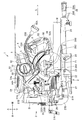
<第1の実施の形態> 以下、本発明の実施の形態に係る卓上切断機について、図1乃至図9に基づいて説明する。図1に示される切断機の一例である卓上切断機1は、ベース部2と、ベース部2と接続する支持部3と、支持部3に支持される切断部4と、により主に構成されている。切断部4は、ハウジング5と、モータ出力軸61(図7)を備えるモータ6と、モータ6により駆動される出力軸7と、出力軸7に着脱可能に装着される切断刃8と、電池パック9が着脱可能に装着される電池パック着脱部10(図2)と、を備えている。支持部3は、本発明の揺動支持機構の一例である。モータ出力軸61は、本発明の回転軸の一例である。 <First Embodiment> Hereinafter, a tabletop cutting machine according to an embodiment of the present invention will be described with reference to FIGS. A tabletop cutting machine 1 which is an example of the cutting machine shown in FIG. 1 is mainly configured by a base part 2, a support part 3 connected to the base part 2, and a cutting part 4 supported by the support part 3. ing. The cutting unit 4 includes a housing 5, a motor 6 having a motor output shaft 61 (FIG. 7), an output shaft 7 driven by the motor 6, a cutting blade 8 detachably attached to the output shaft 7, a battery A battery pack attaching / detaching portion 10 (FIG. 2) to which the pack 9 is detachably attached. The support part 3 is an example of the swing support mechanism of the present invention. The motor output shaft 61 is an example of the rotating shaft of the present invention.
図1において、ベース部2に対して切断部4が設けられている側を上方向と定義して、逆を下方向と定義する。図1における紙面右側を前方と定義し、逆を後方と定義する。図2に示すように、前方から見た左右方向をそれぞれ右方向、左方向と定義する。以下の説明において、上方向等の方向を言う場合には、完全な上方向のみではなく、略上方向についても含むものとする。 In FIG. 1, the side where the cutting portion 4 is provided with respect to the base portion 2 is defined as the upward direction, and the opposite is defined as the downward direction. The right side in FIG. 1 is defined as the front, and the reverse is defined as the rear. As shown in FIG. 2, the left and right directions viewed from the front are defined as a right direction and a left direction, respectively. In the following description, when referring to a direction such as an upward direction, it includes not only a complete upward direction but also a substantially upward direction.
切断部4は、ベース部2に対して出力軸7と平行な後述の揺動軸35A(左右方向に延びる軸)を中心に(軸として)揺動可能である。詳細には、切断部4は、図1に示す切断刃8とベース部2とが最も離間した離間位置と、図6に示す切断刃8が最も下方に位置する近接位置との間を揺動可能である。離間位置は本発明の上死点の一例であり、近接位置は本発明の下死点の一例である。 The cutting portion 4 can swing (as an axis) around a swing shaft 35A (a shaft extending in the left-right direction), which will be described later, parallel to the output shaft 7 with respect to the base portion 2. Specifically, the cutting portion 4 swings between a separation position where the cutting blade 8 and the base portion 2 shown in FIG. 1 are most separated from each other and a proximity position where the cutting blade 8 shown in FIG. Is possible. The separation position is an example of the top dead center of the present invention, and the proximity position is an example of the bottom dead center of the present invention.
切断部4は、出力軸7に直交する後述の傾動軸部27A(前後方向に延びる軸)を中心にベース部2に対して傾動可能である。図2に示すように、前方から見て切断部4は、ベース部2に対して後述の時計回り方向R及び半時計回り方向Lに傾動可能である。図1に示すように、切断部4は、ベース部2に対してスライド方向S(前後方向)に移動可能である。詳細な構成は後述する。 The cutting part 4 can tilt with respect to the base part 2 around a tilting shaft part 27A (an axis extending in the front-rear direction), which will be described later, orthogonal to the output shaft 7. As shown in FIG. 2, the cutting portion 4 can tilt in a clockwise direction R and a counterclockwise direction L described later with respect to the base portion 2 when viewed from the front. As shown in FIG. 1, the cutting part 4 is movable in the sliding direction S (front-rear direction) with respect to the base part 2. A detailed configuration will be described later.
ベース部2は、ベース21と、ベース21上に配置されたターンテーブル22と、ベース21に設けられたフェンス23と、木材Wを固定するためのバイス装置26と、を有する。ベース21及びターンテーブル22の上面は、木材Wを載置する接触面25をなす。ベース21は、図2に示すように、一対の左ベース21Aと右ベース21Bと、により構成される。 The base unit 2 includes a base 21, a turntable 22 disposed on the base 21, a fence 23 provided on the base 21, and a vice device 26 for fixing the wood W. The upper surfaces of the base 21 and the turntable 22 form a contact surface 25 on which the wood W is placed. As shown in FIG. 2, the base 21 includes a pair of a left base 21A and a right base 21B.
図1及び図2に示すように、ターンテーブル22は、ベース21に対して上下方向に延びる図示せぬ回動軸を中心に回転可能であって、右ベース21Bと左ベース21Aとの間に配置されている。ターンテーブル22は、略円台状のターンテーブル本体部22Aと、ターンテーブル本体部22Aから前方に突出する突出部24と、支持部3を支持するハウジング支持部27と、により構成されている。ターンテーブル22の上面には、図示せぬ溝部が形成されている。図示せぬ溝部は、側面視において切断刃8が下方に揺動してターンテーブル22と交わった際の交線位置と同一位置にあり、切断刃8の刃先が収容されて通過する。 As shown in FIGS. 1 and 2, the turntable 22 is rotatable about a rotation shaft (not shown) extending in the vertical direction with respect to the base 21, and between the right base 21B and the left base 21A. Has been placed. The turntable 22 includes a substantially circular turntable main body portion 22A, a protruding portion 24 protruding forward from the turntable main body portion 22A, and a housing support portion 27 that supports the support portion 3. A groove (not shown) is formed on the upper surface of the turntable 22. The groove portion (not shown) is located at the same position as the line of intersection when the cutting blade 8 swings downward and crosses the turntable 22 in a side view, and the cutting edge of the cutting blade 8 is accommodated and passes therethrough.
突出部24には、ターンテーブル22のベース21に対する回動を規制する規制操作部28が設けられている。規制操作部28は突出部24に支持されるとともに、作業者が把持可能であって突出部24から前方へと延出する把持部28Aと、把持部28Aの回転操作により螺進退して突出部24内において前後方向に移動可能で、ベース21に当接・離間可能な後端面を備えた規制部28Bと、を有する。規制部28Bの後端面がベース21に押圧されることで、ターンテーブル22がベース21に対して固定され、ターンテーブル22のベース21に対する回動が抑制される。 The protruding portion 24 is provided with a regulating operation portion 28 that regulates the rotation of the turntable 22 relative to the base 21. The restricting operation portion 28 is supported by the protruding portion 24, and can be gripped by the operator, and extends forward from the protruding portion 24. The restricting operating portion 28 is screwed and retracted by a rotation operation of the holding portion 28A. And a regulating portion 28 </ b> B having a rear end surface that can move in the front-rear direction within 24 and can come into contact with and be separated from the base 21. When the rear end surface of the restricting portion 28B is pressed against the base 21, the turntable 22 is fixed with respect to the base 21, and the turn of the turntable 22 relative to the base 21 is suppressed.
バイス装置26は、上下方向に延びるバイスシャフト26Aと、スクリュホルダ26Bと、ノブ26Cとを備えている。バイスシャフト26Aには、スクリュホルダ26Bが上下方向に移動可能に設けられていて、木材Wのサイズに応じて接触面25からの距離を調整可能である。ノブ26Cを操作することにより、バイス装置26で木材Wを固定することができる。 The vice device 26 includes a vise shaft 26A extending in the vertical direction, a screw holder 26B, and a knob 26C. A screw holder 26B is provided on the vise shaft 26A so as to be movable in the vertical direction, and the distance from the contact surface 25 can be adjusted according to the size of the wood W. The wood W can be fixed by the vice device 26 by operating the knob 26C.
図1に示すように、ハウジング支持部27は、ターンテーブル22の図示せぬ回動軸に関して突出部24の反対位置(図示せぬ回動軸回りに180°回転した位置)に配置されている。即ち、ターンテーブル22の後方に配置されている。ハウジング支持部27は、ターンテーブル22の図示せぬ溝部の延長線上に位置し前後方向に延びる傾動軸部27Aと、最後端部から上方へ向けて直立する傾動支持部27Bとを有している。ハウジング支持部27は、本発明の傾斜角調整機構の一例である。 As shown in FIG. 1, the housing support portion 27 is disposed at a position opposite to the protruding portion 24 with respect to a rotation shaft (not shown) of the turntable 22 (a position rotated 180 ° around a rotation shaft (not shown)). . That is, it is arranged behind the turntable 22. The housing support portion 27 includes a tilt shaft portion 27A that is located on an extension line of a groove portion (not shown) of the turntable 22 and extends in the front-rear direction, and a tilt support portion 27B that stands upright from the rear end portion. . The housing support portion 27 is an example of the tilt angle adjusting mechanism of the present invention.
図2に示すように、傾動支持部27Bには、前後方向に貫通し傾動軸部27Aを中心とした円弧状の長孔27bが形成されている。長孔27b内には、後述のクランプ31Aが挿入されている。傾動支持部27Bには、直角時の位置決め部材となるセットピン29が前後方向に引出可能に装着されている。切断部4は、セットピン29が挿入されている状態では反時計回り方向Lにのみ傾動可能であり、セットピン29が引出された状態では時計回り方向R及び反時計回り方向Lに傾動可能である。傾動軸部27Aは、本発明の傾斜軸の一例である。 As shown in FIG. 2, the tilting support portion 27B is formed with an arc-shaped long hole 27b penetrating in the front-rear direction and centering on the tilting shaft portion 27A. A clamp 31A described later is inserted into the long hole 27b. A set pin 29 serving as a positioning member at a right angle is attached to the tilting support portion 27B so that it can be pulled out in the front-rear direction. The cutting portion 4 can tilt only in the counterclockwise direction L when the set pin 29 is inserted, and can tilt in the clockwise direction R and the counterclockwise direction L when the set pin 29 is pulled out. is there. The tilt shaft portion 27A is an example of the tilt shaft of the present invention.
フェンス23は、ベース21上であって、ターンテーブル22の上方位置に設けられている。フェンス23は、図2に示すように、左ベース21A及び右ベース21Bに対応して左フェンス23A及び右フェンス23Bを有し、左フェンス23A及び右フェンス23Bの前面は、互いに同一平面上に位置するように配置されて、木材W(図1)を位置決めしている。 The fence 23 is provided on the base 21 and above the turntable 22. As shown in FIG. 2, the fence 23 has a left fence 23A and a right fence 23B corresponding to the left base 21A and the right base 21B, and the front surfaces of the left fence 23A and the right fence 23B are located on the same plane. The wood W (FIG. 1) is positioned.
図1及び図2に示すように、支持部3は、ホルダ31と、スライド支持部33と、揺動支持部35と、スライド部36と、を有する。ホルダ31は、傾動軸部27Aを介してハウジング支持部27に支持されている。ホルダ31には、クランプ31Aが螺合しており、クランプ31Aは、傾動支持部27Bの長孔27b(図2)に挿入されている。クランプ31Aを締めることにより、ホルダ31が傾動支持部27Bに固定される。つまり、切断部4が、図2に示す反時計回り方向L及び時計回り方向Rに傾動不能となる。クランプ31Aを緩めることによりホルダ31が傾動軸部27Aを中心に傾動可能になる。つまり、切断部4が、図2に示す反時計回り方向L及び時計回り方向Rに傾動可能になる。クランプ31Aが長孔27bに挿入されているため、ホルダ31が傾動支持部27Bに対して傾動可能な角度は、クランプ31Aが長孔27b内で移動可能な範囲に限定される。 As shown in FIGS. 1 and 2, the support portion 3 includes a holder 31, a slide support portion 33, a swing support portion 35, and a slide portion 36. The holder 31 is supported by the housing support portion 27 via the tilt shaft portion 27A. A clamp 31A is screwed into the holder 31, and the clamp 31A is inserted into a long hole 27b (FIG. 2) of the tilt support portion 27B. By tightening the clamp 31A, the holder 31 is fixed to the tilting support portion 27B. That is, the cutting part 4 cannot be tilted in the counterclockwise direction L and the clockwise direction R shown in FIG. By loosening the clamp 31A, the holder 31 can tilt about the tilting shaft portion 27A. That is, the cutting part 4 can tilt in the counterclockwise direction L and the clockwise direction R shown in FIG. Since the clamp 31A is inserted into the long hole 27b, the angle at which the holder 31 can be tilted with respect to the tilt support portion 27B is limited to a range in which the clamp 31A can move within the long hole 27b.
スライド支持部33は、二本のガイドバー33A、33Bを有する。ガイドバー33A、33Bは、いずれも略同形のパイプ状を成し、上下方向に並列してベース部2の上面(接触面25)と平行かつそれぞれの軸方向が前後方向と一致するように、ホルダ31に固定されている。具体的には、これらガイドバー33A、33Bはそれぞれホルダ31に螺合した図示せぬボルトにより、ホルダ31に脱着不能に固定されている。スライド支持部33は、本発明の摺動支持機構の一例である。ガイドバー33A、33Bは、スライドパイプの一例である。 The slide support portion 33 has two guide bars 33A and 33B. Each of the guide bars 33A and 33B has a substantially identical pipe shape, is parallel to the upper surface (contact surface 25) of the base portion 2 in parallel in the vertical direction, and the respective axial directions coincide with the front-rear direction. It is fixed to the holder 31. Specifically, these guide bars 33A and 33B are fixed to the holder 31 so as not to be detachable by bolts (not shown) screwed to the holder 31, respectively. The slide support portion 33 is an example of a slide support mechanism of the present invention. The guide bars 33A and 33B are examples of slide pipes.
ガイドバー33A,33Bの前端部には、連結部材33Cが設けられている。連結部材33Cによってガイドバー33A、33Bが互いに接続されている。具体的には、連結部材33Cには前後方向に延びる二つの孔が形成されており、この孔内にガイドバー33A、33Bの前端部がそれぞれ挿入、固定される。 A connecting member 33C is provided at the front end of the guide bars 33A and 33B. The guide bars 33A and 33B are connected to each other by the connecting member 33C. Specifically, two holes extending in the front-rear direction are formed in the connecting member 33C, and the front end portions of the guide bars 33A and 33B are inserted and fixed in the holes, respectively.
揺動支持部35は、左右方向に延びる揺動軸35Aと、背面視において上下方向に延びる一対の揺動壁部35Bを有し、スライド部36と一体移動するように構成されている。揺動軸35Aは、一対の揺動壁部35Bの間に架設されて切断部4を揺動可能に軸支している。揺動支持部35には図示せぬバネが装着されており、切断部4を近接位置から離間位置に向かう方向に付勢している。 The swing support portion 35 includes a swing shaft 35A extending in the left-right direction and a pair of swing wall portions 35B extending in the vertical direction when viewed from the back, and is configured to move integrally with the slide portion 36. The swing shaft 35A is installed between the pair of swing wall portions 35B and pivotally supports the cutting portion 4 so as to be swingable. A spring (not shown) is attached to the swing support portion 35 and biases the cutting portion 4 in a direction from the proximity position toward the separation position.
図2に示すように、スライド部36には、前後方向に平行に延びる二つの貫通孔が形成され、この貫通孔内にガイドバー33A、33Bがそれぞれ挿入されている。このスライド部36がガイドバー33A、33Bに対してスライドすることにより、揺動支持部35がスライド方向S(前後方向)に移動可能になる。つまり、切断部4がガイドバー33A、33Bに沿ってスライド方向Sに移動可能になる。スライド部36には、螺進してスライド部36内に突出可能な操作ノブ36Aが螺合している。操作ノブ36Aを螺進させ、ガイドバー33Aをスライド部36に押圧させることにより、ガイドバー33A、33Bに対してスライド部36を固定可能である。 As shown in FIG. 2, the slide portion 36 is formed with two through holes extending in the front-rear direction, and guide bars 33A and 33B are inserted into the through holes, respectively. As the slide portion 36 slides with respect to the guide bars 33A and 33B, the swing support portion 35 can move in the slide direction S (front-rear direction). That is, the cutting part 4 can move in the sliding direction S along the guide bars 33A and 33B. An operation knob 36 </ b> A that can be screwed to protrude into the slide portion 36 is screwed to the slide portion 36. By sliding the operation knob 36A and pressing the guide bar 33A against the slide part 36, the slide part 36 can be fixed to the guide bars 33A and 33B.
図1及び図2に示すように、ハウジング5は、モータハウジング50と、作業用ハンドル53と、運搬用ハンドル54と、ギヤ収容部55と、ソーカバー56と、を有する。モータハウジング50は、モータ6(図7)を内部に収容するとともに、電池パック着脱部10と、表示部57と、電池パック9と電気的に接続される接続端子58と、が設けられている。表示部57には、卓上切断機1の駆動音を抑えると共に、電池パック9の消費を抑えるために、モータ6の回転数を低速回転で制御するサイレントモードへの切替スイッチ57Aと、電池パック9の電池残量を表示する電池残量表示スイッチ57Bと、が設けられている。表示部57は、モータハウジング50の左端面に配置されている。図3、図4、図7、図8、図10、及び図12においては、切替スイッチ57Aと電池残量表示スイッチ57Bの表示を省略している。図7及び図8においては、接続端子58の表示を省略している。 As shown in FIGS. 1 and 2, the housing 5 includes a motor housing 50, a work handle 53, a transport handle 54, a gear accommodating portion 55, and a saw cover 56. The motor housing 50 accommodates the motor 6 (FIG. 7) therein, and is provided with a battery pack attaching / detaching portion 10, a display portion 57, and a connection terminal 58 electrically connected to the battery pack 9. . The display unit 57 includes a switch 57A for switching to a silent mode in which the rotational speed of the motor 6 is controlled at low speed, and the battery pack 9 in order to suppress the driving sound of the tabletop cutting machine 1 and the consumption of the battery pack 9. And a remaining battery level display switch 57B for displaying the remaining battery level. The display unit 57 is disposed on the left end surface of the motor housing 50. In FIG. 3, FIG. 4, FIG. 7, FIG. 8, FIG. 10, and FIG. 12, the display of the changeover switch 57A and the battery remaining amount display switch 57B is omitted. 7 and 8, the display of the connection terminal 58 is omitted.
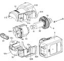
図7に示すように、モータハウジング50は、第1モータハウジング51と第2モータハウジング52とから構成される分割式(2つ割り)ハウジングである。第1モータハウジング51及び第2モータハウジング52は、本発明の分割片の一例である。 As shown in FIG. 7, the motor housing 50 is a split type (divided into two) housings composed of a first motor housing 51 and a second motor housing 52. The 1st motor housing 51 and the 2nd motor housing 52 are examples of the division piece of the present invention.
第1モータハウジング51は、第2モータハウジング52と当接する第1合わせ面51Aと、電池パック9と係合可能な第1レール部51Bと、複数の第1ビス穴部51Cと、を備えている。第1モータハウジング51には、第1電極溝51aと、第1表示溝51bと、が形成されている。第1レール部51Bは、モータ出力軸61と平行に延びていて、第2モータハウジング52に向けて突出している。第1電極溝51a及び第1表示溝51bは、モータ出力軸61と直交する方向に窪むように形成されている。複数の第1ビス穴部51Cは、第1合わせ面51Aから突出したボス形状をなすとともに雌ネジが形成され、モータ出力軸61と直交する方向に形成されている。 The first motor housing 51 includes a first mating surface 51A that contacts the second motor housing 52, a first rail portion 51B that can be engaged with the battery pack 9, and a plurality of first screw hole portions 51C. Yes. The first motor housing 51 is formed with a first electrode groove 51a and a first display groove 51b. The first rail portion 51 </ b> B extends in parallel with the motor output shaft 61 and protrudes toward the second motor housing 52. The first electrode groove 51 a and the first display groove 51 b are formed so as to be recessed in a direction orthogonal to the motor output shaft 61. The plurality of first screw hole portions 51 </ b> C has a boss shape projecting from the first mating surface 51 </ b> A, is formed with a female screw, and is formed in a direction orthogonal to the motor output shaft 61.
第2モータハウジング52は、第1合わせ面51Aと当接する第2合わせ面52Aと、電池パック9と係合可能な第2レール部52Bと、壁部52Cとを備えている。第2モータハウジング52には、第2電極溝52aと、第2表示溝52bと、複数の第2ビス穴52cと、が形成されている。第1合わせ面51Aと第2合わせ面52Aとは、モータ出力軸61と平行に延びる平面上で当接される構造をしている。つまり、モータ出力軸61に直交する方向から見て、第1合わせ面51A、第2合わせ面52Aとモータ出力軸61とは平行である。実施の形態の構造では、第1合わせ面51Aと第2合わせ面52Aとを含む平面上に、モータ出力軸61が位置される構造をしている。第2レール部52Bは、モータ出力軸61と平行に延び、第1モータハウジング51に向けて突出している。第1合わせ面51A及び第2合わせ面52Aは、本発明の合わせ面の一例である。第1レール部51B及び第2レール部52Bは、本発明のレール部の一例である。 The second motor housing 52 includes a second mating surface 52A that contacts the first mating surface 51A, a second rail portion 52B that can be engaged with the battery pack 9, and a wall portion 52C. In the second motor housing 52, a second electrode groove 52a, a second display groove 52b, and a plurality of second screw holes 52c are formed. The first mating surface 51A and the second mating surface 52A are in contact with each other on a plane extending in parallel with the motor output shaft 61. That is, when viewed from the direction orthogonal to the motor output shaft 61, the first mating surface 51A, the second mating surface 52A, and the motor output shaft 61 are parallel. In the structure of the embodiment, the motor output shaft 61 is positioned on a plane including the first mating surface 51A and the second mating surface 52A. The second rail portion 52 </ b> B extends in parallel with the motor output shaft 61 and protrudes toward the first motor housing 51. The first mating surface 51A and the second mating surface 52A are examples of the mating surface of the present invention. The first rail part 51B and the second rail part 52B are examples of the rail part of the present invention.
壁部52Cは、モータ出力軸61を回転可能に支承している。第1モータハウジング51にも図示せぬ壁部が設けられており、図示せぬ壁部と壁部52Cとが当接することにより、モータ6が収容される空間が区画される。第2電極溝52a及び第2表示溝52bは、モータ出力軸61と直交する方向に窪むように形成される。モータ6と、表示部57と、接続端子58と、を内部に配置した状態で第1モータハウジング51と第2モータハウジング52とを結合すると、第1電極溝51a及び第2電極溝52aによって接続端子58が挟持され、第1表示溝51b及び第2表示溝52bによって表示部57が挟持される。複数の第2ビス穴52cは、第1ビス穴部51Cのボスを受入可能に構成され、第2モータハウジング52をモータ出力軸61と直交する方向に貫通している。 The wall portion 52C supports the motor output shaft 61 to be rotatable. The first motor housing 51 is also provided with a wall portion (not shown), and a space in which the motor 6 is accommodated is defined by the contact of the wall portion (not shown) and the wall portion 52C. The second electrode groove 52 a and the second display groove 52 b are formed so as to be recessed in a direction orthogonal to the motor output shaft 61. When the first motor housing 51 and the second motor housing 52 are coupled with the motor 6, the display unit 57, and the connection terminal 58 disposed therein, the first electrode groove 51a and the second electrode groove 52a are connected. The terminal 58 is sandwiched, and the display unit 57 is sandwiched by the first display groove 51b and the second display groove 52b. The plurality of second screw holes 52c are configured to receive the bosses of the first screw hole portions 51C, and penetrate the second motor housing 52 in a direction orthogonal to the motor output shaft 61.
第1モータハウジング51と第2モータハウジング52とを結合すると、第1レール部51B及び第2レール部52Bがそれぞれモータ出力軸61と平行に延び、電池パック着脱部10がモータハウジング50に形成される。第1モータハウジング51と第2モータハウジング52とは、図示せぬビスが対応する第2ビス穴52cを貫通して第1ビス穴部51Cの雌ネジと螺合することにより互いに固定されている。図示せぬビスは、第2モータハウジング52側から第1モータハウジング51側に向けて挿入される。これによって、第1ビス穴部51C及び第2ビス穴52cは略下方に向かって開口するため、それぞれの穴に粉塵等が堆積することを防止できる。 When the first motor housing 51 and the second motor housing 52 are coupled, the first rail portion 51B and the second rail portion 52B extend in parallel with the motor output shaft 61, and the battery pack attaching / detaching portion 10 is formed in the motor housing 50. The The first motor housing 51 and the second motor housing 52 are fixed to each other by screwing with a female screw of the first screw hole 51C through a second screw hole 52c corresponding to a screw (not shown). . A screw (not shown) is inserted from the second motor housing 52 side toward the first motor housing 51 side. As a result, the first screw hole 51C and the second screw hole 52c open substantially downward, so that dust or the like can be prevented from accumulating in the respective holes.
電池パック着脱部10及びモータ6は、出力軸7に対して出力軸7と直交する方向に配置されている。換言すると、図3及び図4に示すように、電池パック9と、電池パック着脱部10と、モータ6とは、切断刃8の半径方向外方に位置している。電池パック9は、第1レール部51B及び第2レール部52Bが延びる方向(着脱方向D)に沿って、電池パック着脱部10に対して着脱可能である。図2に示すように、第1レール部51B及び第2レール部52Bの延出方向、つまり着脱方向Dは左右方向である。換言すると、着脱方向Dは、正面視において切断部4のスライド方向Sに直交している。電池パック9を装着する際には、正面視において右方向に差し込む。セットピン29によって切断部4の傾動が反時計回り方向Lにのみ許容されている場合には、電池パック9の装着方向(右方向)は切断部4の傾動方向と略反対方向になる。図2の状態で電池パック9を着脱方向Dに沿って装着する場合は、時計回り方向Rへの傾動が規制されているため、電池パック9の装着によって切断部4が時計回り方向Rに傾動することを防止できる。 The battery pack attaching / detaching portion 10 and the motor 6 are arranged in a direction perpendicular to the output shaft 7 with respect to the output shaft 7. In other words, as shown in FIGS. 3 and 4, the battery pack 9, the battery pack attaching / detaching portion 10, and the motor 6 are positioned radially outward of the cutting blade 8. The battery pack 9 can be attached to and detached from the battery pack attaching / detaching part 10 along the direction (attaching / detaching direction D) in which the first rail part 51B and the second rail part 52B extend. As shown in FIG. 2, the extending direction of the first rail part 51B and the second rail part 52B, that is, the attaching / detaching direction D is the left-right direction. In other words, the attachment / detachment direction D is orthogonal to the slide direction S of the cutting part 4 in a front view. When the battery pack 9 is mounted, the battery pack 9 is inserted in the right direction when viewed from the front. When tilting of the cutting part 4 is allowed only in the counterclockwise direction L by the set pin 29, the mounting direction (right direction) of the battery pack 9 is substantially opposite to the tilting direction of the cutting part 4. When the battery pack 9 is mounted along the attachment / detachment direction D in the state of FIG. 2, since the tilting in the clockwise direction R is restricted, the cutting portion 4 is tilted in the clockwise direction R by the mounting of the battery pack 9. Can be prevented.
電池パック着脱部10は、図6に示すように、切断部4が近接位置にあるときには、モータハウジング50の前部に位置している。図3及び図4、図5に示すように、モータハウジング50の左端部は、電池パック着脱部10に装着された電池パック9の左端部よりも右側に位置している。換言すると、電池パック9の長手方向の長さは、モータ6及びモータハウジング50の長手方向の長さよりも長い。電池パック9が電池パック着脱部10に装着されることにより、電池パック9の電力が接続端子58を介して卓上切断機1に供給可能となる。 As shown in FIG. 6, the battery pack attaching / detaching portion 10 is located at the front portion of the motor housing 50 when the cutting portion 4 is in the close position. As shown in FIGS. 3, 4, and 5, the left end portion of the motor housing 50 is located on the right side of the left end portion of the battery pack 9 attached to the battery pack attaching / detaching portion 10. In other words, the length of the battery pack 9 in the longitudinal direction is longer than the lengths of the motor 6 and the motor housing 50 in the longitudinal direction. By attaching the battery pack 9 to the battery pack attaching / detaching portion 10, the power of the battery pack 9 can be supplied to the desktop cutting machine 1 via the connection terminal 58.
図1に示すように、作業用ハンドル53は、電池パック着脱部10及びモータハウジング50の前方に設けられ、切断部4が離間位置にあるときには切断刃8の上方に位置している。作業用ハンドル53は側面視略D字形状をなし、モータ6のオン・オフを制御するスイッチトリガ53Aが設けられている。作業者は作業用ハンドル53を把持して、切断部4を離間位置から近接位置に移動させることができる。 As shown in FIG. 1, the work handle 53 is provided in front of the battery pack attaching / detaching portion 10 and the motor housing 50, and is located above the cutting blade 8 when the cutting portion 4 is in the separated position. The work handle 53 is substantially D-shaped when viewed from the side, and is provided with a switch trigger 53A for controlling on / off of the motor 6. The operator can hold the work handle 53 and move the cutting unit 4 from the separated position to the close position.
運搬用ハンドル54は、作業用ハンドル53の後方かつモータハウジング50の後方に設けられている。作業用ハンドル53と運搬用ハンドル54とは、側面視において切断刃8の側面と平行な方向(略前後方向)に並んで配置される。作業用ハンドル53と運搬用ハンドル54との間には、モータ6と、電池パック着脱部10と、電池パック9とが配置されている。「作業用ハンドル53と運搬用ハンドル54との間」とは、側面視において作業用ハンドル53と運搬用ハンドル54とを帯状に結んだ場合、当該帯と少なくとも一部が重複することをいう。図6に示すように、運搬用ハンドル54は切断部4が近接位置にあるときには略水平となり、図示せぬロックピンにより切断部4を近接位置に固定した状態で卓上切断機1を運搬する際に作業者が把持しやすくなる。 The transport handle 54 is provided behind the work handle 53 and behind the motor housing 50. The work handle 53 and the transport handle 54 are arranged side by side in a direction (substantially front-rear direction) parallel to the side surface of the cutting blade 8 in a side view. Between the work handle 53 and the transport handle 54, the motor 6, the battery pack attaching / detaching portion 10, and the battery pack 9 are arranged. “Between the work handle 53 and the transport handle 54” means that when the work handle 53 and the transport handle 54 are connected in a band shape in a side view, at least a part of the band overlaps. As shown in FIG. 6, the transport handle 54 is substantially horizontal when the cutting portion 4 is in the close position, and is used for transporting the tabletop cutting machine 1 with the cutting portion 4 fixed at the close position by a lock pin (not shown). This makes it easier for the operator to grip.
運搬用ハンドル54は、作業者が卓上切断機1を運搬する時に把持する運搬把持部54Aを備えている。図6の2点鎖線で示すように、運搬把持部54Aの上端部は、電池パック着脱部10に装着された電池パック9よりも上方に位置している。これによって、運搬時においては上下方向の寸法が抑えられ、コンパクトな状態での運搬が可能となる。運搬用ハンドル54には、把持穴54aが形成されていて、切断部4が近接位置にあるときには把持穴54aは略前後方向に延びている。 The transport handle 54 includes a transport grip portion 54 </ b> A that is gripped when an operator transports the tabletop cutting machine 1. As shown by a two-dot chain line in FIG. 6, the upper end portion of the carrying grip portion 54 </ b> A is located above the battery pack 9 attached to the battery pack attaching / detaching portion 10. Thereby, the size in the vertical direction is suppressed during transportation, and transportation in a compact state becomes possible. A gripping hole 54a is formed in the carrying handle 54, and the gripping hole 54a extends substantially in the front-rear direction when the cutting portion 4 is in the close position.
図3に示すように、ギヤ収容部55は、モータハウジング50の右側に位置している。図1に示すように、ギヤ収容部55は、側面視においてモータハウジング50と重複する位置であって、作業用ハンドル53と運搬用ハンドル54との間に位置している。ギヤ収容部55には、複数のギヤから構成され、モータ6から切断刃8に駆動力を伝達する図示せぬ駆動力伝達機構が収容されている。図1及び図2に示すように、ギヤ収容部55には、前方に延びフレキシブル支持部55Bに支持される照明用のLED55Aが設けられている。作業者は、フレキシブル支持部55Bの操作により、LED55Aを所望の場所に照射することができる。 As shown in FIG. 3, the gear housing 55 is located on the right side of the motor housing 50. As shown in FIG. 1, the gear housing portion 55 is located at a position overlapping the motor housing 50 in a side view, and is located between the work handle 53 and the transport handle 54. The gear housing 55 is composed of a plurality of gears, and houses a driving force transmission mechanism (not shown) that transmits driving force from the motor 6 to the cutting blade 8. As shown in FIGS. 1 and 2, the gear housing 55 is provided with an LED 55A for illumination that extends forward and is supported by the flexible support 55B. The operator can irradiate the LED 55A to a desired place by operating the flexible support portion 55B.
ソーカバー56は、ギヤ収容部55の左側面に設けられていて、切断刃8の上半分を覆っている。ソーカバー56内には、ソーカバー56から露出する切断刃8の下側の外周を覆う鋸カバー56Aが、出力軸7を中心に回動可能に設けられている。鋸カバー56Aは、図1に示すように、切断部4が離間位置にあるときには、ソーカバー56から露出する切断刃8の外周を覆っている。鋸カバー56Aは、図6に示すように、切断部4が近接位置にあるときには、図示しないリンク機構によって出力軸7を中心に回動してソーカバー56内に収納され、切断刃8の下半分をソーカバー56から露出させる。 The saw cover 56 is provided on the left side surface of the gear housing portion 55 and covers the upper half of the cutting blade 8. A saw cover 56 </ b> A covering the lower outer periphery of the cutting blade 8 exposed from the saw cover 56 is provided in the saw cover 56 so as to be rotatable about the output shaft 7. As shown in FIG. 1, the saw cover 56 </ b> A covers the outer periphery of the cutting blade 8 exposed from the saw cover 56 when the cutting portion 4 is in the separated position. As shown in FIG. 6, the saw cover 56 </ b> A is rotated around the output shaft 7 by a link mechanism (not shown) and stored in the saw cover 56 when the cutting portion 4 is in the close position, and the lower half of the cutting blade 8. Is exposed from the saw cover 56.
モータ6はブラシレスモータであって、図7に示すように、モータ出力軸61と、モータ出力軸61に固定されたロータ62と、モータ出力軸61の径方向においてロータ62と対向するステータ63と、ステータ63の左端部に固定されたインバータ回路64と、モータ出力軸61に固定された冷却ファン65と、を備えている。図2に示すように、モータ出力軸61は左右方向に延びている。モータ出力軸61の右端部はギヤ収容部55に収容された図示せぬ駆動力伝達機構と係合し、モータ出力軸61の左端部は壁部52Cに回転可能に支承されている。 The motor 6 is a brushless motor, and as shown in FIG. 7, a motor output shaft 61, a rotor 62 fixed to the motor output shaft 61, and a stator 63 facing the rotor 62 in the radial direction of the motor output shaft 61 The inverter circuit 64 is fixed to the left end of the stator 63, and the cooling fan 65 is fixed to the motor output shaft 61. As shown in FIG. 2, the motor output shaft 61 extends in the left-right direction. The right end portion of the motor output shaft 61 is engaged with a driving force transmission mechanism (not shown) housed in the gear housing portion 55, and the left end portion of the motor output shaft 61 is rotatably supported on the wall portion 52C.
図9に示すように、ロータ62は2組の磁石から構成され、ステータ63は当該磁石と対向するコイルを備えている。インバータ回路64は、モータ6の駆動を制御するための6つのスイッチング素子64Aと、ステータ63の位置検出のための磁気センサ15と、を備えている。磁気センサ15は、例えばホール素子であり、ロータ62と左右方向において対向している。図4に示すように、インバータ回路64は、ステータ63の左端部に設けられている。図5に示すように、モータ出力軸61の軸方向において、ステータ63とインバータ回路64とは電池パック9の全長に収まるように配置されている。換言すると、モータ出力軸61に直交し電池パック着脱部10を通る方向から見て、電池パック9(電池パック着脱部10)とステータ63及びインバータ回路64とは互いに重なっている。 As shown in FIG. 9, the rotor 62 includes two sets of magnets, and the stator 63 includes a coil facing the magnets. The inverter circuit 64 includes six switching elements 64 </ b> A for controlling driving of the motor 6 and a magnetic sensor 15 for detecting the position of the stator 63. The magnetic sensor 15 is a Hall element, for example, and faces the rotor 62 in the left-right direction. As shown in FIG. 4, the inverter circuit 64 is provided at the left end portion of the stator 63. As shown in FIG. 5, in the axial direction of the motor output shaft 61, the stator 63 and the inverter circuit 64 are arranged so as to fit in the entire length of the battery pack 9. In other words, the battery pack 9 (battery pack attaching / detaching portion 10), the stator 63, and the inverter circuit 64 overlap each other when viewed from the direction orthogonal to the motor output shaft 61 and passing through the battery pack attaching / detaching portion 10.
切断部4には、制御部11(図9)を有する図示せぬ制御回路基板が設けられている。制御部11は、インバータ回路64の駆動制御及びLED55Aの制御を行う。インバータ回路64は、モータ6と、制御部11と、電池パック9と、電気的に接続されている。モータ6の駆動電流の経路には、電流検出用の検出抵抗12と、電池パック9と並列に接続されたコンデンサ13と、が設けられている。 The cutting unit 4 is provided with a control circuit board (not shown) having the control unit 11 (FIG. 9). The control unit 11 performs drive control of the inverter circuit 64 and control of the LED 55A. The inverter circuit 64 is electrically connected to the motor 6, the control unit 11, and the battery pack 9. In the drive current path of the motor 6, a detection resistor 12 for current detection and a capacitor 13 connected in parallel with the battery pack 9 are provided.
制御部11は、制御電源回路14と、電流検出回路16と、スイッチ操作検出回路17と、電圧検出回路18と、回転位置検出回路19と、回転数検出回路20と、演算部41と、制御信号回路42と、を備えている。制御電源回路14は、電池パック9の電圧を制御部11の動作に適した電圧に変換して制御部11に供給する。電流検出回路16は、検出抵抗12の端子電圧によりモータ6の駆動電流を検出する。スイッチ操作検出回路17は、作業者によるスイッチトリガ53Aの操作量を検出する。電圧検出回路18は、コンデンサ13によりモータ6の駆動電圧を検出する。回転位置検出回路19は、磁気センサ15からの信号に基づいて、モータ6の回転位置を検出する。回転数検出回路20は、回転位置検出回路19からの信号に基づいて、モータ6の回転数を検出する。演算部41は、スイッチ操作検出回路17からの信号に基づいて、スイッチトリガ53Aの操作量に応じて、インバータ回路64の各スイッチング素子64Aに印加するPWM信号のデューティ比(以下、デューティ比と称す)を設定する。演算部41は、設定したデューティ比、及び回転位置検出回路19で検出したモータ6の回転位置に応じて、制御信号回路42を駆動し、インバータ回路64の各スイッチング素子64Aをスイッチング制御する。演算部41は、回転位置検出回路19の検出結果に基づいてモータ6の回転数を算出し、設定されたモータ6と切断刃8との減速比に基づいて回転位置検出回路19の検出結果から切断刃8の回転数を検出する。 The control unit 11 includes a control power supply circuit 14, a current detection circuit 16, a switch operation detection circuit 17, a voltage detection circuit 18, a rotation position detection circuit 19, a rotation number detection circuit 20, a calculation unit 41, a control And a signal circuit 42. The control power supply circuit 14 converts the voltage of the battery pack 9 into a voltage suitable for the operation of the control unit 11 and supplies it to the control unit 11. The current detection circuit 16 detects the drive current of the motor 6 based on the terminal voltage of the detection resistor 12. The switch operation detection circuit 17 detects the operation amount of the switch trigger 53A by the operator. The voltage detection circuit 18 detects the drive voltage of the motor 6 by the capacitor 13. The rotational position detection circuit 19 detects the rotational position of the motor 6 based on the signal from the magnetic sensor 15. The rotation speed detection circuit 20 detects the rotation speed of the motor 6 based on the signal from the rotation position detection circuit 19. The computing unit 41 is based on the signal from the switch operation detection circuit 17 and according to the operation amount of the switch trigger 53A, the duty ratio of the PWM signal applied to each switching element 64A of the inverter circuit 64 (hereinafter referred to as the duty ratio). ) Is set. The calculation unit 41 drives the control signal circuit 42 according to the set duty ratio and the rotational position of the motor 6 detected by the rotational position detection circuit 19, and performs switching control of each switching element 64 </ b> A of the inverter circuit 64. The calculation unit 41 calculates the rotation speed of the motor 6 based on the detection result of the rotation position detection circuit 19, and based on the detection result of the rotation position detection circuit 19 based on the set reduction ratio between the motor 6 and the cutting blade 8. The rotational speed of the cutting blade 8 is detected.
制御部11には、レーザ駆動回路43と照明LED駆動回路44とが接続されている。レーザ駆動回路43は、レーザ43Aと接続されており、レーザスイッチ43Bの操作に基づいて、レーザ43Aを照射する。作業者は、レーザ43Aにより照射されたレーザ光を基準として、木材Wを切断することができる。照明LED駆動回路44は、LED55Aと接続されており、LEDスイッチ44Aの操作に基づいて、照明用のLED55Aを点灯する。 A laser drive circuit 43 and an illumination LED drive circuit 44 are connected to the control unit 11. The laser drive circuit 43 is connected to the laser 43A and irradiates the laser 43A based on the operation of the laser switch 43B. The operator can cut the wood W with reference to the laser beam irradiated by the laser 43A. The illumination LED drive circuit 44 is connected to the LED 55A, and turns on the illumination LED 55A based on the operation of the LED switch 44A.
次に、卓上切断機1の切断作業について説明する。作業者は、電池パック9を着脱方向Dに沿って電池パック着脱部10に装着する。そして、スイッチトリガ53Aを引いてモータ6を駆動させて切断刃8を回転させ、作業用ハンドル53を下方に押下げることで、切断部4を下方へ移動させる。このとき、揺動支持部35を中心(軸)として切断部4が左側面視時計回り方向に揺動することにより、切断部4は下方へ移動する。切断刃8と木材Wとを接触させて切断を開始し、切断部4をスライド支持部33(ガイドバー33A、33B)に対してスライドさせて切断部4を後方へと移動させ、木材Wの切断を行う。 Next, the cutting operation of the tabletop cutting machine 1 will be described. The operator attaches the battery pack 9 to the battery pack attaching / detaching portion 10 along the attaching / detaching direction D. Then, the switch trigger 53A is pulled to drive the motor 6 to rotate the cutting blade 8, and the work handle 53 is pushed downward to move the cutting portion 4 downward. At this time, the cutting part 4 is moved downward by swinging the cutting part 4 in the clockwise direction in the left side view with the swing support part 35 as the center (axis). The cutting blade 8 and the wood W are brought into contact with each other to start cutting, and the cutting portion 4 is slid with respect to the slide support portion 33 (guide bars 33A and 33B) to move the cutting portion 4 rearward. Disconnect.
木材Wを斜めに切断するときは、切断刃8の両側面を接触面25に対して傾斜させる。切断部4を図2の時計回り方向Rに傾動させる場合には、セットピン29をホルダ31内から完全に退避させてクランプ31Aを緩める。または、クランプ31Aを緩めてからセットピン29をホルダ31内から退避させても良い。これにより、ベース部2に対して支持部3及び切断部4が反時計回り方向L及び時計回り方向Rに傾動可能になる。反時計回り方向L又は時計回り方向Rの何れかに傾いた切断部4は、ホルダ31が図示せぬストッパボルトに当接することにより、その最大傾斜角が定められている。最大傾斜角を45°とするには、ホルダ31が45°に傾いた状態でホルダ31に当接するように、図示せぬストッパボルトを調節する。  When the wood W is cut obliquely, both side surfaces of the cutting blade 8 are inclined with respect to the contact surface 25. When the cutting portion 4 is tilted in the clockwise direction R of FIG. 2, the set pin 29 is completely retracted from the holder 31 and the clamp 31A is loosened. Alternatively, the set pin 29 may be retracted from the holder 31 after the clamp 31A is loosened. Thereby, the support part 3 and the cutting part 4 can be tilted in the counterclockwise direction L and the clockwise direction R with respect to the base part 2. The cutting portion 4 inclined in either the counterclockwise direction L or the clockwise direction R has its maximum inclination angle determined by the holder 31 coming into contact with a stopper bolt (not shown). In order to set the maximum inclination angle to 45 °, a stopper bolt (not shown) is adjusted so that the holder 31 is in contact with the holder 31 while being inclined at 45 °. *
以上、本発明の第1の実施の形態に係る卓上切断機について説明をしたが、このような構成によると、電池パック9の着脱方向D(図2)は、切断部4の揺動方向、つまり、切断刃8の側面と交差(直交)する方向となり、電池パック9着脱操作によって切断部4が揺動し難く、着脱操作を容易に行うことができる。また、切断部4が意図せずに揺動することを抑制し、ベース21上に載置した木材Wの損傷を抑制することができる。 As described above, the tabletop cutting machine according to the first embodiment of the present invention has been described. According to such a configuration, the attachment / detachment direction D (FIG. 2) of the battery pack 9 is the swinging direction of the cutting unit 4, That is, it becomes a direction intersecting (orthogonal) with the side surface of the cutting blade 8, and the cutting portion 4 is not easily swung by the attaching / detaching operation of the battery pack 9, so that the attaching / detaching operation can be easily performed. Moreover, it can suppress that the cutting | disconnection part 4 rock | fluctuates unintentionally, and can suppress the damage of the timber W mounted on the base 21. FIG.
また、このような構成によると、電池パック着脱部10をモータハウジング50に設けることができるため、電池パック着脱部10を構成するハウジングを別途用意する必要がなく、部品点数の削減及び切断部の小型化を図ることができる。そのため、簡易な構成によって電池パック着脱部10を製作及び組立できる。また、電池パック着脱部10からモータ6までリード線等を配線する際、他のハウジングを介せずに配線できるので構造を簡単にすることができ、組み立ても容易である。 Further, according to such a configuration, since the battery pack attaching / detaching portion 10 can be provided in the motor housing 50, there is no need to separately prepare a housing constituting the battery pack attaching / detaching portion 10, and the number of parts can be reduced and the cutting portion can be reduced. Miniaturization can be achieved. Therefore, the battery pack attaching / detaching portion 10 can be manufactured and assembled with a simple configuration. Further, when wiring a lead wire or the like from the battery pack attaching / detaching portion 10 to the motor 6, it is possible to wire without passing through another housing, so that the structure can be simplified and the assembly is also easy.
また、このような構成によると、第1レール部51Bは第1モータハウジング51に設けられていて、第2レール部52Bは第2モータハウジング52に設けられているため、レール部を長手方向、電池パックの着脱方向において分断せずに製作することが可能である。これにより、レール部の精度が確保され、電池パック9の滑らかな着脱が可能となる。 Further, according to such a configuration, the first rail portion 51B is provided in the first motor housing 51, and the second rail portion 52B is provided in the second motor housing 52. The battery pack can be manufactured without being divided in the attaching / detaching direction. Thereby, the precision of a rail part is ensured and the battery pack 9 can be smoothly attached or detached.
また、このような構成によると、接続端子58が第1モータハウジング51及び第2モータハウジング52に挟持されるように組み立てられるため、接続端子58をモータハウジング50に取付けるための金具等が不要である。これにより、接続端子58を確実に保持しつつモータハウジング50を容易に組立てることができる。 Further, according to such a configuration, since the connection terminal 58 is assembled so as to be sandwiched between the first motor housing 51 and the second motor housing 52, a metal fitting for attaching the connection terminal 58 to the motor housing 50 is unnecessary. is there. Thereby, the motor housing 50 can be easily assembled while the connection terminal 58 is securely held.
また、このような構成によると、表示部57が第1モータハウジング51及び第2モータハウジング52に挟持されるように組み立てられるため、これらの部品をモータハウジング50に取付けるための金具等が不要である。これにより、表示部57を確実に保持しつつモータハウジング50を容易に組立てることができる。 In addition, according to such a configuration, the display unit 57 is assembled so as to be sandwiched between the first motor housing 51 and the second motor housing 52, so that metal fittings for attaching these components to the motor housing 50 are not necessary. is there. Thereby, the motor housing 50 can be easily assembled while the display portion 57 is securely held.
また、このような構成によると、モータハウジング50の突出端部が電池パック9よりも内側に配置されるため、全幅を抑えた小型の卓上切断機1とすることができる。 Moreover, according to such a structure, since the protrusion edge part of the motor housing 50 is arrange | positioned inside the battery pack 9, it can be set as the small desktop cutting machine 1 which suppressed the full width.
また、このような構成によると、電池パック着脱部10が運搬用ハンドル54と作業用ハンドル53との間に設けられることで電池パック着脱部10から両ハンドルへの距離が短くなるため、電池パック9の保持時においてどちらかのハンドルを握って切断部4を安定させることが容易となる。 According to such a configuration, since the battery pack attaching / detaching portion 10 is provided between the transport handle 54 and the work handle 53, the distance from the battery pack attaching / detaching portion 10 to both the handles is shortened. At the time of holding 9, it becomes easy to grasp one of the handles to stabilize the cutting portion 4.
また、このような構成によると、切断部4を下死点位置に固定した状態(図6)において電池パック9が運搬用ハンドル54より下方に位置するため、運搬時において全高を抑えた小型の卓上切断機1とすることができる In addition, according to such a configuration, since the battery pack 9 is positioned below the transport handle 54 in a state where the cutting portion 4 is fixed at the bottom dead center position (FIG. 6), a small size that suppresses the overall height during transport. Can be a tabletop cutting machine 1
また、このような構成によると、電池パック9の着脱方向Dが切断部4の摺動方向Sと直交する。そのため、電池パック9着脱操作によって切断部4が摺動し難く、電池パック9の着脱作業を行い易くできる。また、ベース21上に載置した木材Wの損傷を抑制することができる。 Moreover, according to such a structure, the attachment / detachment direction D of the battery pack 9 is orthogonal to the sliding direction S of the cutting part 4. Therefore, it is difficult for the cutting portion 4 to slide by the battery pack 9 attaching / detaching operation, and the attaching / detaching operation of the battery pack 9 can be easily performed. In addition, damage to the wood W placed on the base 21 can be suppressed.
また、電池パック9の長手方向(左右方向)の寸法内にモータ6、接続端子58、インバータ回路64、表示部57を収めた構成とすることで、切断部4の左右方向の寸法(全幅)を抑えた小型の卓上切断機1とすることができる。 In addition, since the motor 6, the connection terminal 58, the inverter circuit 64, and the display unit 57 are accommodated in the longitudinal (left / right) dimension of the battery pack 9, the left / right dimension (full width) of the cutting unit 4. It can be set as the small desk-top cutting machine 1 which suppressed this.
また、このような構成によると、電池パック9、インバータ回路64、表示部57などDC駆動の卓上切断機1特有の構成をモータハウジング50に集約しているため、モータハウジング50以外の構成をACで駆動する切断機と共通にすることができる。これにより、卓上切断機1の製造コストを削減することができる。 Further, according to such a configuration, the configuration unique to the DC-driven tabletop cutting machine 1 such as the battery pack 9, the inverter circuit 64, and the display unit 57 is concentrated in the motor housing 50. It can be shared with the cutting machine driven by Thereby, the manufacturing cost of the tabletop cutting machine 1 can be reduced.
上述の実施の形態では、電池パック9の着脱方向Dは切断刃8の側面と直交する方向であったが、着脱方向Dと切断刃8の側面とが交差する方向であってもよい。これにより、装着方向における鉛直方向の成分が少なくなるため、切断部4が揺動することを抑制することができる。以下、その変形例について説明する。 In the above-described embodiment, the attachment / detachment direction D of the battery pack 9 is a direction orthogonal to the side surface of the cutting blade 8, but may be a direction in which the attachment / detachment direction D and the side surface of the cutting blade 8 intersect. Thereby, since the component of the perpendicular direction in a mounting direction decreases, it can suppress that the cutting | disconnection part 4 rock | fluctuates. Hereinafter, the modification is demonstrated.
<第2の実施の形態> 本発明の変形例である第2の実施の形態について、図10乃至図12に基づいて説明する。第1の実施の形態と同一の構成は、同一の符号を付し説明を省略する。第2の実施の形態では、電池パック9の着脱方向Dが第1の実施の形態と異なっている。 Second Embodiment A second embodiment which is a modification of the present invention will be described with reference to FIGS. The same configurations as those of the first embodiment are denoted by the same reference numerals and description thereof is omitted. In the second embodiment, the attachment / detachment direction D of the battery pack 9 is different from that of the first embodiment.
モータハウジング150は、第1モータハウジング151と、第2モータハウジング152とから構成されており、両者が互いに固定されると電池パック着脱部110が形成される。モータハウジング150には、接続端子158が設けられている。モータハウジング150は、図11に示すように、正面視において斜め左上方向に延びている。また、図10に示すように、切断部4が離間位置にあるときは、モータハウジング150は前後方向に傾斜するとともに、上下方向にも傾斜している。図12に示すように、切断部4が近接位置にあるときには、上下方向に傾斜している。第1の実施の形態と同様に、モータハウジング150と、モータ出力軸61と、第1レール部51Bと、第2レール部52Bと、はいずれも同一方向に延びている。 The motor housing 150 includes a first motor housing 151 and a second motor housing 152. When both are fixed to each other, a battery pack attaching / detaching portion 110 is formed. A connection terminal 158 is provided on the motor housing 150. As shown in FIG. 11, the motor housing 150 extends obliquely in the upper left direction when viewed from the front. Further, as shown in FIG. 10, when the cutting portion 4 is in the separated position, the motor housing 150 is inclined in the front-rear direction and also in the vertical direction. As shown in FIG. 12, when the cutting part 4 is in the proximity position, it is inclined in the vertical direction. As in the first embodiment, the motor housing 150, the motor output shaft 61, the first rail portion 51B, and the second rail portion 52B all extend in the same direction.
図11に示すように、電池パック9の着脱方向D2は、正面視において斜め左上方向である。着脱方向D2は、切断刃8の側面(上下方向に延びる垂直面)に交差する方向であり、切断部4が近接位置にあるとき(図11の状態)には、正面視において斜め左上と斜め右下とを結ぶ方向である。図10に示すように、切断部4が離間位置にあるときには、着脱方向Dはスライド方向Sと交差している。図11、図12に示すように、切断部4が近接位置にあるときには、着脱方向Dはスライド方向Sと直交している。つまり、切断部4が近接位置にあるときには、平面視において着脱方向Dとスライド方向Sとが略直交する。 As shown in FIG. 11, the attachment / detachment direction D2 of the battery pack 9 is an obliquely upper left direction in a front view. The attachment / detachment direction D2 is a direction that intersects the side surface (vertical surface extending in the vertical direction) of the cutting blade 8, and when the cutting portion 4 is in the close position (state of FIG. 11), it is obliquely upper left and oblique in the front view. It is the direction connecting the lower right. As shown in FIG. 10, the attachment / detachment direction D intersects the slide direction S when the cutting part 4 is in the separation position. As shown in FIGS. 11 and 12, the attachment / detachment direction D is orthogonal to the slide direction S when the cutting portion 4 is in the close position. That is, when the cutting part 4 is in the close position, the attaching / detaching direction D and the sliding direction S are substantially orthogonal in a plan view.
このような構成によると、切断部4が近接位置にあるときにおいて、意図せぬ切断部4の摺動を抑制することができると共に、切断部4を反時計回り方向Lに傾動させた場合に、モータハウジング150とベース部2との距離が離れるため、より多く反時計回り方向Lに傾動させることができる。さらに、切断部4を反時計回り方向Lに傾動させた状態で、切断部4とベース部2との間にスペースを確保することができるため、電池パック9が着脱し易くなるとともに、表示部の確認及び操作がし易くなる。さらに、表示部57が上方向を向くため、表示部の確認及び操作がし易くなる。 According to such a configuration, when the cutting portion 4 is in the close position, unintentional sliding of the cutting portion 4 can be suppressed, and when the cutting portion 4 is tilted in the counterclockwise direction L. Since the distance between the motor housing 150 and the base portion 2 is increased, the motor housing 150 can be tilted more in the counterclockwise direction L. Furthermore, since the space can be secured between the cutting portion 4 and the base portion 2 in a state where the cutting portion 4 is tilted in the counterclockwise direction L, the battery pack 9 can be easily attached and detached, and the display portion It becomes easy to confirm and operate. Furthermore, since the display unit 57 faces upward, it is easy to check and operate the display unit.
本発明による切断機は、上述の実施の形態に限定されず、例えば特許請求の範囲に記載された発明の要旨の範囲内で種々の変更が可能である。例えば、本発明では切断機として卓上切断機1を用いたが、携帯用切断機に用いることもできる。 The cutting machine by this invention is not limited to the above-mentioned embodiment, For example, a various change is possible within the range of the summary of the invention described in the claim. For example, in the present invention, the tabletop cutting machine 1 is used as a cutting machine, but it can also be used for a portable cutting machine.
上述の実施の形態では、モータハウジング50は、モータ出力軸61に直交する方向から見て、モータ6のモータ出力軸61の軸方向と平行にのびる第1合わせ面51A及び第2合わせ面52Aを有する2つ割りハウジングであったが、これに限定されない。例えば、一体成型されたモータハウジングであってもよく、モータ出力軸の軸方向に直交する合わせ面を有する分割式(2つ割り)ハウジングであってもよい。 In the above-described embodiment, the motor housing 50 includes the first mating surface 51A and the second mating surface 52A extending parallel to the axial direction of the motor output shaft 61 of the motor 6 when viewed from the direction orthogonal to the motor output shaft 61. Although it was the split housing which has, it is not limited to this. For example, an integrally molded motor housing may be used, or a split type (divided into two) housings having a mating surface orthogonal to the axial direction of the motor output shaft may be used.
上述の実施の形態では、モータハウジング50は第1モータハウジング51と第2モータハウジング52の2つ割りハウジングで構成されたが、これに限定されない。3つ以上に分割されるハウジングで構成されていてもよい。その場合には、接続端子及び表示部は、3つ以上に分割されるハウジングのうちの少なくとも2つに挟持されていることが望ましい。 In the above-described embodiment, the motor housing 50 is constituted by the two-split housing of the first motor housing 51 and the second motor housing 52, but is not limited to this. You may be comprised with the housing divided | segmented into 3 or more. In that case, it is desirable that the connection terminal and the display unit are sandwiched between at least two of the housings divided into three or more.
上述の実施の形態では、電池パック着脱部10は、切断部4が近接位置にあるときには(図6)、モータハウジング50の前方に設けられたが、これに限定されない。例えば、電池パック着脱部がモータハウジング50の後方に配置されていても良い。また、電池パック着脱部は、第1モータハウジング又は第2モータハウジングのいずれか一方側に配置されていても良い。 In the above-described embodiment, the battery pack attaching / detaching portion 10 is provided in front of the motor housing 50 when the cutting portion 4 is in the close position (FIG. 6), but is not limited thereto. For example, the battery pack attaching / detaching portion may be disposed behind the motor housing 50. Further, the battery pack attaching / detaching portion may be disposed on either one of the first motor housing and the second motor housing.
上述の実施の形態では、モータ6はブラシレスモータを用いたが、ブラシ付きモータを用いてもよい。 In the embodiment described above, the motor 6 is a brushless motor, but a brush motor may be used.
上述の実施の形態では、電池パック着脱部10をモータハウジング50に設けたが、これに限定されない。切断部4のハウジング5上であれば、電池パック9の着脱方向Dが切断刃8の側面と交差する方向であることを条件に、任意の位置に設けることができる。例えば、作業用ハンドル53や運搬用ハンドル54等に設けてもよく、ギヤ収容部55に設けてもよい。 In the above-described embodiment, the battery pack attaching / detaching portion 10 is provided in the motor housing 50. However, the present invention is not limited to this. If it is on the housing 5 of the cutting part 4, it can be provided at an arbitrary position on condition that the attaching / detaching direction D of the battery pack 9 is a direction intersecting the side surface of the cutting blade 8. For example, it may be provided on the work handle 53, the transport handle 54, or the like, or may be provided on the gear housing 55.
電池パック9の着脱方向は上述の実施の形態に限られず、切断刃8の側面と交差する方向であれば、他の方向であってもよい。 The attachment / detachment direction of the battery pack 9 is not limited to the above-described embodiment, and may be another direction as long as it intersects the side surface of the cutting blade 8.
上述の実施の形態ではスライド式、または傾斜可能な卓上切断機1を用いたが、これに限らずスライド機構を用いない、または傾斜しない切断機においても、本発明の適用は可能であり、スライド構造も切断部4がガイドバー33A、33B上を摺動する構造に限らず、切断部4とガイドバー33A、33Bと共に摺動する構造であってもよい。 In the above-described embodiment, the slide-type or tiltable tabletop cutting machine 1 is used. However, the present invention is not limited to this, and the present invention can be applied to a cutting machine that does not use or does not tilt. The structure is not limited to the structure in which the cutting portion 4 slides on the guide bars 33A and 33B, but may be a structure that slides together with the cutting portion 4 and the guide bars 33A and 33B.
1…卓上切断機、2…ベース部、3…支持部、4…切断部、5…ハウジング、6…モータ、7…出力軸、8…切断刃、9…電池パック、10…電池パック着脱部、21…ベース、27…ハウジング支持部、27A…傾動軸部、35A…揺動軸、33…スライド支持部、33A,33B…ガイドバー、36…スライド部、50,150…モータハウジング、51,151…第1モータハウジング、51A…第1合わせ面、51B…第1レール部、52,152…第2モータハウジング、52A…第2合わせ面、52B…第2レール部、53…作業用ハンドル、54…運搬用ハンドル、53A…スイッチトリガ、57…表示部、57A…切替スイッチ、58…接続端子、62…ロータ、63…ステータ、64…インバータ回路 DESCRIPTION OF SYMBOLS 1 ... Desktop cutting machine, 2 ... Base part, 3 ... Support part, 4 ... Cutting part, 5 ... Housing, 6 ... Motor, 7 ... Output shaft, 8 ... Cutting blade, 9 ... Battery pack, 10 ... Battery pack attaching / detaching part 21 ... Base, 27 ... Housing support, 27A ... Tilt shaft, 35A ... Swing shaft, 33 ... Slide support, 33A, 33B ... Guide bar, 36 ... Slide, 50, 150 ... Motor housing, 51, 151 ... First motor housing, 51A ... First mating surface, 51B ... First rail portion, 52, 152 ... Second motor housing, 52A ... Second mating surface, 52B ... Second rail portion, 53 ... Working handle, 54 ... Handle for transport, 53A ... Switch trigger, 57 ... Display section, 57A ... Changeover switch, 58 ... Connection terminal, 62 ... Rotor, 63 ... Stator, 64 ... Inverter circuit

Claims (11)

  1. モータと、該モータを収容するモータハウジングと、該モータの回転により回転し切断刃を着脱可能な出力軸と、該モータの動力源となる電池パックと、該電池パックが着脱可能に係合する一対のレール部を有する電池パック着脱部と、を備える切断部を有し、被加工材を載置可能な接触面を有するベースと、該ベースと該切断部とに接続され、該出力軸と平行な揺動軸を備え、該切断部を上死点と下死点との間で該揺動軸を中心として該切断刃の側面と平行な方向に揺動可能に支持する揺動支持機構と、を有する切断機であって、該一対のレール部は該切断刃の側面と交差する方向に延びることを特徴とする切断機。  A motor, a motor housing that houses the motor, an output shaft that is rotated by the rotation of the motor and that can be attached to and detached from the cutting blade, a battery pack that is a power source of the motor, and the battery pack are detachably engaged. A battery pack attaching / detaching portion having a pair of rail portions, a base having a contact surface on which a work material can be placed, a base connected to the base and the cutting portion, and the output shaft A swing support mechanism that includes a parallel swing shaft and supports the cutting portion so as to be swingable between a top dead center and a bottom dead center about the swing shaft in a direction parallel to the side surface of the cutting blade. And the pair of rail portions extend in a direction intersecting with a side surface of the cutting blade.
  2. 該電池パック着脱部は、該モータハウジングに設けられることを特徴とする請求項1記載の切断機。  The cutting machine according to claim 1, wherein the battery pack attaching / detaching portion is provided in the motor housing.
  3. 該モータハウジングは、該モータの回転軸の軸方向に平行な合わせ面によって分割可能な少なくとも2つの分割片から構成され、該一対のレール部の一方と他方はそれぞれ、該少なくとも2つの分割片のうち互いに異なる分割片に設けられることを特徴とする請求項2に記載の切断機。 The motor housing is composed of at least two divided pieces that can be divided by a mating surface parallel to the axial direction of the rotating shaft of the motor, and one and the other of the pair of rail portions are respectively the at least two divided pieces. The cutting machine according to claim 2, wherein the cutting machines are provided in different divided pieces.
  4. 該電池パック着脱部に設けられ該モータに電気的に接続する接続端子と、をさらに有し、該接続端子は、該少なくとも2つの分割片に挟持されることを特徴とする請求項3に記載の切断機。  The battery pack further includes a connection terminal provided in the battery pack attaching / detaching portion and electrically connected to the motor, wherein the connection terminal is sandwiched between the at least two divided pieces. Cutting machine.
  5. 該電池パックの残量を表示する電池残量表示部が該少なくとも2つの分割片に挟持されることを特徴とする請求項3または4に記載の切断機。  The cutting machine according to claim 3 or 4, wherein a battery remaining amount display unit for displaying the remaining amount of the battery pack is sandwiched between the at least two divided pieces.
  6. 該モータは、該モータハウジング内に固定されるステータを有するブラシレスモータであり、該ステータ及び該モータの出力を制御するインバータ回路は、該モータの回転軸の軸方向において該電池パックの全長内に収まるように配置されることを特徴とする請求項5に記載の切断機。  The motor is a brushless motor having a stator fixed in the motor housing, and the inverter circuit for controlling the output of the stator and the motor is within the entire length of the battery pack in the axial direction of the rotation shaft of the motor. The cutting machine according to claim 5, wherein the cutting machine is arranged so as to be accommodated.
  7. 該切断部は、作業者が操作することで該モータのオン・オフを切り替えるトリガを有する作業用ハンドルと、運搬用ハンドルとをさらに有し、該作業用ハンドルと該運搬用ハンドルは該切断刃の側面と平行な方向に並んで配置され、該電池パック着脱部は、該切断刃の側面と平行な方向において該運搬用ハンドルと該作業用ハンドルとの間に設けられることを特徴とする請求項1乃至6のいずれか1項に記載の切断機。  The cutting unit further includes a work handle having a trigger for switching on and off of the motor when operated by an operator, and a transport handle. The work handle and the transport handle include the cutting blade. The battery pack attaching / detaching portion is disposed between the carrying handle and the working handle in a direction parallel to the side surface of the cutting blade. Item 7. The cutting machine according to any one of Items 1 to 6.
  8. 該切断部が該下死点に位置するとき、装着された該電池パックは該運搬用ハンドルより下方に位置することを特徴とする請求項7に記載の切断機。  The cutting machine according to claim 7, wherein when the cutting portion is located at the bottom dead center, the mounted battery pack is located below the carrying handle.
  9. 該切断部を該接触面と平行な摺動方向に摺動可能に支持する摺動支持機構をさらに備え、該一対のレール部は、該切断部が該下死点に位置する場合に、該摺動方向と直交する方向に延びることを特徴とする請求項1乃至8のいずれか1項に記載の切断機。  A sliding support mechanism that slidably supports the cutting portion in a sliding direction parallel to the contact surface, and the pair of rail portions are configured so that when the cutting portion is located at the bottom dead center, The cutting machine according to any one of claims 1 to 8, wherein the cutting machine extends in a direction orthogonal to the sliding direction.
  10. 該摺動支持機構は、スライドパイプを有し、該スライドパイプは該切断部を摺動可能に支持することを特徴とする請求項9に記載の切断機。  The cutting machine according to claim 9, wherein the sliding support mechanism includes a slide pipe, and the slide pipe supports the cutting portion so as to be slidable.
  11. 該モータと該電池パック着脱部はそれぞれ、該出力軸に対し該出力軸の直交方向上に配置されることを特徴とする請求項1乃至10のいずれか1項に記載の切断機。 The cutting machine according to any one of claims 1 to 10, wherein the motor and the battery pack attaching / detaching portion are respectively disposed in a direction orthogonal to the output shaft with respect to the output shaft.
PCT/JP2016/063519 2015-05-29 2016-04-29 Cutting machine WO2016194536A1 (en)

Priority Applications (6)

Application Number Priority Date Filing Date Title
EP21184295.0A EP3912776B1 (en) 2015-05-29 2016-04-29 Cutting machine
EP16802973.4A EP3305487B1 (en) 2015-05-29 2016-04-29 Cutting machine
CN201680033202.3A CN107635734B (en) 2015-05-29 2016-04-29 cutting machine
JP2017521751A JP6284071B2 (en) 2015-05-29 2016-04-29 Cutting machine
US15/577,628 US10286462B2 (en) 2015-05-29 2016-04-29 Cutting machine
US16/408,082 US10888938B2 (en) 2015-05-29 2019-05-09 Cutting machine

Applications Claiming Priority (2)

Application Number Priority Date Filing Date Title
JP2015109864 2015-05-29
JP2015-109864 2015-05-29

Related Child Applications (2)

Application Number Title Priority Date Filing Date
US15/577,628 A-371-Of-International US10286462B2 (en) 2015-05-29 2016-04-29 Cutting machine
US16/408,082 Continuation US10888938B2 (en) 2015-05-29 2019-05-09 Cutting machine

Publications (1)

Publication Number Publication Date
WO2016194536A1 true WO2016194536A1 (en) 2016-12-08

Family

ID=57440015

Family Applications (1)

Application Number Title Priority Date Filing Date
PCT/JP2016/063519 WO2016194536A1 (en) 2015-05-29 2016-04-29 Cutting machine

Country Status (5)

Country Link
US (2) US10286462B2 (en)
EP (2) EP3912776B1 (en)
JP (1) JP6284071B2 (en)
CN (1) CN107635734B (en)
WO (1) WO2016194536A1 (en)

Cited By (6)

* Cited by examiner, † Cited by third party
Publication number Priority date Publication date Assignee Title
JP2018065222A (en) * 2016-10-20 2018-04-26 マックス株式会社 Portable Cutting Machine
JP2018089867A (en) * 2016-12-05 2018-06-14 株式会社マキタ Cutting machine
WO2019111632A1 (en) * 2017-12-06 2019-06-13 株式会社マキタ Stationary sawing machine for metal work
CN113227498A (en) * 2019-01-11 2021-08-06 罗贝尔铁路建筑机械有限责任公司 Cutting sander and method for cutting through a rail of a track
WO2021166392A1 (en) * 2020-02-17 2021-08-26 株式会社マキタ Work machine
WO2022254907A1 (en) * 2021-06-04 2022-12-08 工機ホールディングス株式会社 Work machine

Families Citing this family (8)

* Cited by examiner, † Cited by third party
Publication number Priority date Publication date Assignee Title
EP3912776B1 (en) 2015-05-29 2023-11-22 Koki Holdings Co., Ltd. Cutting machine
US10543542B2 (en) * 2016-07-27 2020-01-28 Tti (Macao Commercial Offshore) Limited Miter saw
WO2020066902A1 (en) 2018-09-28 2020-04-02 工機ホールディングス株式会社 Work machine
JP7118862B2 (en) * 2018-10-30 2022-08-16 株式会社マキタ Cutting machine
DE102018222159A1 (en) * 2018-12-18 2020-06-18 Robert Bosch Gmbh Machine tool
CN112223433A (en) * 2019-07-15 2021-01-15 株式会社牧田 Automatic planer
US20220168828A1 (en) * 2020-12-02 2022-06-02 Makita Corporation Sliding cutting machine
CN217452379U (en) * 2022-05-10 2022-09-20 南京泉峰科技有限公司 Table type cutting device

Citations (4)

* Cited by examiner, † Cited by third party
Publication number Priority date Publication date Assignee Title
WO2012108415A1 (en) * 2011-02-10 2012-08-16 株式会社マキタ Electric tool
JP2014079812A (en) * 2011-10-20 2014-05-08 Makita Corp Cutting machine
JP2014144508A (en) * 2013-01-29 2014-08-14 Hitachi Koki Co Ltd Desktop cutter
JP2014148015A (en) * 2013-02-01 2014-08-21 Makita Corp Charging type cutting tool

Family Cites Families (14)

* Cited by examiner, † Cited by third party
Publication number Priority date Publication date Assignee Title
JP3558880B2 (en) * 1998-07-09 2004-08-25 株式会社マキタ Tabletop marunoco board
JP2000308268A (en) 1999-04-15 2000-11-02 Makita Corp Charge system of electrical tool
CN201271763Y (en) 2008-09-26 2009-07-15 王伟鹏 Improved cutting machine
US8302519B2 (en) * 2008-12-31 2012-11-06 Techtronic Power Tools Technology Limited Hand-held power tool
EP2397277A4 (en) * 2009-02-10 2014-07-02 Makita Corp Motor-driven tool
JP5410843B2 (en) * 2009-06-02 2014-02-05 株式会社マキタ Cutting machine
JP2011099349A (en) * 2009-11-04 2011-05-19 Denso Corp Abnormality diagnosing device for alcohol sensor
JP5461221B2 (en) * 2010-02-12 2014-04-02 株式会社マキタ Electric tool powered by multiple battery packs
JP5432761B2 (en) * 2010-02-12 2014-03-05 株式会社マキタ Electric tool powered by multiple battery packs
JP6100004B2 (en) 2013-02-01 2017-03-22 株式会社マキタ Tabletop cutting machine
US20150328796A1 (en) 2013-02-01 2015-11-19 Makita Corporation Cutting device
EP3912776B1 (en) 2015-05-29 2023-11-22 Koki Holdings Co., Ltd. Cutting machine
CN208866497U (en) * 2018-08-23 2019-05-17 创科(澳门离岸商业服务)有限公司 Cut-in type annular saw
DE102018215308A1 (en) * 2018-09-10 2020-03-12 Robert Bosch Gmbh Vacuum cleaner

Patent Citations (4)

* Cited by examiner, † Cited by third party
Publication number Priority date Publication date Assignee Title
WO2012108415A1 (en) * 2011-02-10 2012-08-16 株式会社マキタ Electric tool
JP2014079812A (en) * 2011-10-20 2014-05-08 Makita Corp Cutting machine
JP2014144508A (en) * 2013-01-29 2014-08-14 Hitachi Koki Co Ltd Desktop cutter
JP2014148015A (en) * 2013-02-01 2014-08-21 Makita Corp Charging type cutting tool

Non-Patent Citations (1)

* Cited by examiner, † Cited by third party
Title
See also references of EP3305487A4 *

Cited By (10)

* Cited by examiner, † Cited by third party
Publication number Priority date Publication date Assignee Title
JP2018065222A (en) * 2016-10-20 2018-04-26 マックス株式会社 Portable Cutting Machine
JP2018089867A (en) * 2016-12-05 2018-06-14 株式会社マキタ Cutting machine
WO2018105494A1 (en) * 2016-12-05 2018-06-14 株式会社マキタ Cutting machine
US11027344B2 (en) 2016-12-05 2021-06-08 Makita Corporation Cutting device
WO2019111632A1 (en) * 2017-12-06 2019-06-13 株式会社マキタ Stationary sawing machine for metal work
CN113227498A (en) * 2019-01-11 2021-08-06 罗贝尔铁路建筑机械有限责任公司 Cutting sander and method for cutting through a rail of a track
CN113227498B (en) * 2019-01-11 2023-07-18 罗贝尔铁路建筑机械有限责任公司 Cutting sander and method for cutting through a rail of a track
WO2021166392A1 (en) * 2020-02-17 2021-08-26 株式会社マキタ Work machine
US11938607B2 (en) 2020-02-17 2024-03-26 Makita Corporation Power tool with light emitter
WO2022254907A1 (en) * 2021-06-04 2022-12-08 工機ホールディングス株式会社 Work machine

Also Published As

Publication number Publication date
EP3305487A4 (en) 2019-01-02
CN107635734B (en) 2019-01-01
CN107635734A (en) 2018-01-26
JP6284071B2 (en) 2018-02-28
JPWO2016194536A1 (en) 2018-02-22
US10888938B2 (en) 2021-01-12
EP3912776A1 (en) 2021-11-24
US20190262916A1 (en) 2019-08-29
EP3305487A1 (en) 2018-04-11
EP3912776B1 (en) 2023-11-22
EP3305487B1 (en) 2021-12-08
US10286462B2 (en) 2019-05-14
US20180161891A1 (en) 2018-06-14

Similar Documents

Publication Publication Date Title
JP6284071B2 (en) Cutting machine
JP6100004B2 (en) Tabletop cutting machine
US10589412B2 (en) Rechargeable electric power tool
US11278973B2 (en) Rechargeable shear
CN101642834A (en) Handheld reciprocating saw and operating method thereof
WO2018105494A1 (en) Cutting machine
JP2014231130A (en) Cordless circular saw
JP5398993B2 (en) Cutting machine body
JP6274522B2 (en) Cutting machine
JP7061915B2 (en) Circular saw
JP6946152B2 (en) Parallel ruler and portable processing machine
JP2018043372A (en) Portable processor
JP6615851B2 (en) Tabletop cutting machine
JP6881134B2 (en) Electric tool
JP7151619B2 (en) Cutting machine
JP6570701B2 (en) Portable Marunoko and portable cutting machine
JP2013078864A (en) Portable cutting machine
JP2015123540A (en) Power tool
JP2021104617A (en) Cutting machine
JP2023009616A (en) electric work machine
JP6317001B2 (en) Tabletop cutting machine
JP7049783B2 (en) All screw cutters
JP6862868B2 (en) Portable cutting machine using a base
JPWO2020066903A1 (en) Work machine
JP2016187855A (en) Band saw

Legal Events

Date Code Title Description
121 Ep: the epo has been informed by wipo that ep was designated in this application

Ref document number: 16802973

Country of ref document: EP

Kind code of ref document: A1

ENP Entry into the national phase

Ref document number: 2017521751

Country of ref document: JP

Kind code of ref document: A

WWE Wipo information: entry into national phase

Ref document number: 15577628

Country of ref document: US

NENP Non-entry into the national phase

Ref country code: DE

WWE Wipo information: entry into national phase

Ref document number: 2016802973

Country of ref document: EP