WO2016194353A1 - Masque - Google Patents
Masque Download PDFInfo
- Publication number
- WO2016194353A1 WO2016194353A1 PCT/JP2016/002595 JP2016002595W WO2016194353A1 WO 2016194353 A1 WO2016194353 A1 WO 2016194353A1 JP 2016002595 W JP2016002595 W JP 2016002595W WO 2016194353 A1 WO2016194353 A1 WO 2016194353A1
- Authority
- WO
- WIPO (PCT)
- Prior art keywords
- resin film
- mask
- film
- holes
- hole
- Prior art date
Links
Images


Classifications
-
- A—HUMAN NECESSITIES
- A62—LIFE-SAVING; FIRE-FIGHTING
- A62B—DEVICES, APPARATUS OR METHODS FOR LIFE-SAVING
- A62B23/00—Filters for breathing-protection purposes
- A62B23/02—Filters for breathing-protection purposes for respirators
- A62B23/025—Filters for breathing-protection purposes for respirators the filter having substantially the shape of a mask
-
- A—HUMAN NECESSITIES
- A41—WEARING APPAREL
- A41D—OUTERWEAR; PROTECTIVE GARMENTS; ACCESSORIES
- A41D13/00—Professional, industrial or sporting protective garments, e.g. surgeons' gowns or garments protecting against blows or punches
- A41D13/05—Professional, industrial or sporting protective garments, e.g. surgeons' gowns or garments protecting against blows or punches protecting only a particular body part
- A41D13/11—Protective face masks, e.g. for surgical use, or for use in foul atmospheres
-
- A—HUMAN NECESSITIES
- A62—LIFE-SAVING; FIRE-FIGHTING
- A62B—DEVICES, APPARATUS OR METHODS FOR LIFE-SAVING
- A62B18/00—Breathing masks or helmets, e.g. affording protection against chemical agents or for use at high altitudes or incorporating a pump or compressor for reducing the inhalation effort
- A62B18/02—Masks
-
- A—HUMAN NECESSITIES
- A41—WEARING APPAREL
- A41D—OUTERWEAR; PROTECTIVE GARMENTS; ACCESSORIES
- A41D2500/00—Materials for garments
- A41D2500/50—Synthetic resins or rubbers
- A41D2500/52—Synthetic resins or rubbers in sheet form
-
- A—HUMAN NECESSITIES
- A41—WEARING APPAREL
- A41D—OUTERWEAR; PROTECTIVE GARMENTS; ACCESSORIES
- A41D31/00—Materials specially adapted for outerwear
- A41D31/04—Materials specially adapted for outerwear characterised by special function or use
- A41D31/10—Impermeable to liquids, e.g. waterproof; Liquid-repellent
- A41D31/102—Waterproof and breathable
Definitions
- the present invention provides a mask to be used on the face, and more specifically, protects the wearer from dust, splashes, contaminants, allergens, pathogens, etc.
- the present invention relates to a mask that ensures breathing of a wearer while suppressing splashing of splashes and pathogens.
- masks worn on the face are widely used, and their production and usage are increasing year by year.
- their production and usage are increasing year by year.
- masks are used to inhale pathogens, pollen and allergens, and to prevent splashes, pollutants, pathogens, etc. from being scattered around by their breathing, coughing or sneezing.
- PM2.5 inhalation of allergens and pollutants
- service industries such as food production and provision
- the mask includes, for example, a main body that covers at least a part of the wearer's face, typically a nostril and a mouth, and a locking portion that fixes the main body to the wearer's face.
- a main body made of a nonwoven fabric or a woven fabric is generally used. While breathing of the wearer is ensured by the breathability of the non-woven fabric or woven fabric, the function of the filter prevents inhalation and / or scattering from the wearer of the substance as described above.
- the main body made of non-woven fabric or woven fabric is usually opaque, the portion of the wearer's face covered with the mask is hidden.
- a more specific example is that a part of the wearer's face is hidden when the mask is used by a health care worker or a service provider that touches the customer's eyes.
- a mask having a body part that is as transparent as possible may be required in order to suppress the occurrence of a sense of incongruity or misidentification of a person, or to ensure good communication by being able to confirm the expression of the wearer.
- a transparent resin film or a very thin woven or non-woven fabric has been conventionally used.
- Masks having a transparent main body are disclosed in, for example, Patent Documents 1 to 3.
- the mask protects the wearer from dust and the like, and suppresses splashing from the wearer (hereinafter collectively referred to as “shielding”). Say). In addition, since light is scattered by the fibers constituting the woven or non-woven fabric, it is actually difficult to ensure high transparency.
- the main body portion made of a transparent resin film the main body portion itself can realize high shielding properties and can ensure high transparency by appropriately selecting the material of the film.
- the resin film itself does not have air permeability, the masking performance as a mask is reduced by necessitating a gap between the face and the main body to ensure the breathing of the wearer.
- the present invention is a mask having a completely different structure from a conventional mask, and has a high degree of freedom in designing various characteristics such as shielding properties, air permeability, transparency, and sound permeability, for example, good shielding properties.
- An object of the present invention is to provide a mask that can be compatible with air permeability, air permeability, transparency and sound permeability.
- the mask of the present invention is a mask used by being mounted on a face, and a main body portion covering at least a part of the face includes a resin film having air permeability in the thickness direction.
- the resin film is a non-porous film having a plurality of through holes extending in the thickness direction.
- the diameter of the through hole is 0.01 ⁇ m or more and 30 ⁇ m or less.
- the density of the through holes in the resin film is 10 / cm 2 or more and 1 ⁇ 10 8 / cm 2 or less.
- the mask has a completely different structure from the conventional mask, and has a high degree of freedom in designing various characteristics including shielding properties, air permeability, transparency, and sound permeability.
- a mask having excellent shielding properties, air permeability, transparency and sound permeability can be realized.
- FIG. 2 is a view showing a mask manufactured in Example 1.
- FIG. It is a figure which shows the result of the shielding evaluation test implemented in the Example.
- a first aspect of the present disclosure is a mask used by being attached to a face, and a main body portion covering at least a part of the face includes a resin film having air permeability in a thickness direction, and the resin film includes: , A non-porous film having a plurality of through holes extending in the thickness direction, the diameter of the through holes being 0.01 ⁇ m or more and 30 ⁇ m or less, and the density of the through holes in the resin film being 10 / cm 2.
- a mask that is 1 ⁇ 10 8 pieces / cm 2 or less.
- the second aspect of the present disclosure provides a mask in which the resin film is made of a transparent material in addition to the first aspect.
- the third aspect of the present disclosure provides a mask in which the plurality of through holes extend in a direction perpendicular to the main surface of the resin film in addition to the first or second aspect.
- a mask in which a ratio t / R of the thickness t of the resin film to the diameter R of the through hole is 1 or more and 10,000 or less is provided. To do.
- the air permeability in the thickness direction of the resin film is indicated by a fragile number measured in accordance with JIS L1096.
- a mask that is 3 / (cm 2 ⁇ sec) or more is provided.
- the sixth aspect of the present disclosure provides a mask in which the sound pressure loss at a frequency of 1 kHz of the resin film is 5 dB or less in addition to any of the first to fifth aspects.
- the resin film is made of at least one material selected from polyethylene terephthalate, polycarbonate, polyimide, polyethylene naphthalate, and polyvinylidene fluoride. Provide a mask to be used.
- FIG. 1 shows an example of the mask of the present invention in a state where the wearer wears it on the face.
- the mask 1 shown in FIG. 1 includes a main body 2 that covers a part of the face of the wearer 51, more specifically, a nostril 52 and a mouth 53, and a member for fixing the main body 2 to the face of the wearer 51.
- the stop part 3 is provided.
- the locking portion 3 is joined to the main body 2 at the edge 4 of the main body 2.
- the locking portion 3 is a string-like member, and the mask 1 is mounted on the face of the wearer 51 by putting the locking portion 3 on the ear of the wearer 51.
- the main body 2 is composed of a resin film 5.
- the resin film 5 has air permeability in the thickness direction.
- the resin film 5 is a non-porous film having a plurality of through holes extending in the thickness direction.
- the diameter of the through holes is 0.01 ⁇ m or more and 30 ⁇ m or less, and the density (hole density) of the through holes in the resin film 5 is 10 pieces / cm 2 or more and 1 ⁇ 10 8 pieces / cm 2 or less.
- the main body 2 since the main body 2 includes the resin film 5, the breathing of the wearer 51 is ensured even when the peripheral edge of the main body 2 is in close contact with the face of the wearer 51. Moreover, in combination with the diameter and density of the through holes in the predetermined range in the resin film 5, it is possible to achieve good shielding and sound transmission. And the transparency of the mask 1 provided with the main-body part 2 and the main-body part 2 can also be ensured by using a transparent material for the resin film 5. FIG. That is, in the mask 1, for example, good shielding properties, air permeability, transparency, and sound permeability can be arranged side by side.
- the resin film 5 can be satisfactorily subjected to various processes such as a liquid repellent process, a coloring process, an antifogging process, or a printing process that is limited in nonwoven fabrics and woven fabrics.
- Various characteristics and / or functions can be imparted to the main body 2 and the mask 1 including the main body 2.
- various characteristics including the above-described four characteristics can be changed. That is, the mask 1 is a mask having a high degree of freedom in designing various characteristics including shielding properties, air permeability, transparency, and sound permeability.
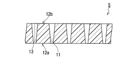
- FIG. 2 shows an example of the resin film 5.
- the resin film 5 is formed with a plurality of through holes 11 penetrating in the thickness direction.
- the through hole 11 extends in a straight line, and the area of a cross section perpendicular to the extending direction (hereinafter simply referred to as “cross section of the through hole”) extends from one main surface 12 a to the other main surface 12 b of the resin film 5. It is constant until.
- the through hole 11 penetrates the substrate structure of the resin film 5. In other words, the through hole 11 has a structure different from the substrate of the resin film 5.
- the resin film 5 is a non-porous film that does not have a path that allows ventilation in the thickness direction other than the through holes 11.
- the resin film 5 is non-porous (solid) except for the through holes 11. It is a film. That is, the substrate structure of the resin film 5 is non-porous, and the through hole 11 penetrates the non-porous structure.
- the through hole 11 is a straight hole in which the central axis (axis) 13 of the through hole extends linearly.
- the through-hole 11 can be formed, for example, by ion beam irradiation on the original film of the resin film 5 and subsequent chemical etching, or laser irradiation on the original film.
- the resin film 5 may be a film obtained by ion beam irradiation and chemical etching on the original film, or a film obtained by laser irradiation on the original film.
- the structure of such a resin film 5 is greatly different from the structure of a woven fabric and a non-woven fabric that have been conventionally used as a main body of a mask.
- a woven fabric and a non-woven fabric since random voids existing between fibers serve as a ventilation path, the ventilation path has innumerable branching and merging, and cannot be a straight hole.
- strong light scattering due to random voids is unavoidable, and it is actually difficult to achieve high transparency. It can be said that the substrate structure itself of the woven fabric and the nonwoven fabric is a porous structure.
- the high uniformity of the diameter of the through-holes 11 formed in the non-porous substrate structure means that the mask 1 provided with the resin film 5 in the main body 2 is more reliable in terms of shielding properties, air permeability and sound permeability, for example.
- the resin film 5 is made of a transparent material, it contributes to the realization of the mask 1 having higher transparency by further suppressing the light scattering in the resin film 5. .
- the through-hole 11 is formed so as to penetrate the non-porous substrate structure, not only its diameter but also its shape (including the change in cross-sectional shape and cross-sectional area).
- the density in the resin film 5 can be controlled with higher accuracy and higher uniformity. This also contributes to a higher degree of freedom in designing various characteristics such as shielding properties, air permeability, transparency, and sound permeability in the mask 1.
- the diameter of the through hole 11 is 0.01 ⁇ m or more and 30 ⁇ m or less. In this range, the degree of freedom in designing the various characteristics is increased. Focusing on the masking property of the mask 1, the size of the virus is about 0.1 to 1 ⁇ m, the size of the bacteria and the droplet containing the virus or bacteria is about 1 to 10 ⁇ m, the size of the pollen is about 30 ⁇ m, and PM2.5 The size of the contaminants (particles) is about 0.1 to several tens ⁇ m, and general dust is a larger size. Therefore, the mask 1 provided with the resin film 5 in the main body 2 shields these substances.
- the diameter of the through-hole 11 it can cope with Although it is theoretically possible to make the diameter of the through-hole 11 less than 0.01 ⁇ m, the industrial productivity of the resin film 5 is lowered, and it can be said that the diameter is excessively small in consideration of the size of the virus. .
- the diameter of the through hole 11 is less than 0.01 ⁇ m, it becomes difficult to maintain a balance between characteristics, particularly a balance between shielding properties and air permeability, for the mask 1 including the resin film 5 in the main body 2.
- the diameter of the through-hole 11 exceeds 30 ⁇ m, the shielding property of the mask 1 provided with the resin film 5 in the main body 2 is lowered.
- the density (hole density) of the through holes 11 in the resin film 5 is 10 pieces / cm 2 or more and 1 ⁇ 10 8 pieces / cm 2 or less. Coupled with the diameter of the through-hole 11 being 0.01 ⁇ m or more and 30 ⁇ m or less, the degree of freedom in designing the above-mentioned various characteristics is increased in this range. For example, good shielding properties, air permeability, and sound permeability are compatible. In addition, in the case of the mask 1 having transparency, higher transparency can be achieved.
- the diameter of the through hole 11 is different in concept from the average hole diameter of the resin film 5.
- the diameters of all the through holes 11 (opening diameters) present in the main surfaces 12 a and 12 b, or all the penetrations present in the effective part of the resin film 5 (parts that can be used as applications of the film).
- the diameter of the hole 11 can fall within the above range.
- the shape of the cross section of the through hole 11 and the shape of the opening are not particularly limited, and are, for example, a circle or an ellipse. At this time, these shapes do not need to be exact circles or ellipses, and for example, some shape disturbances that cannot be avoided by the manufacturing method described later are allowed.
- the diameter of the circle when the shape of the opening is regarded as a circle in other words, the diameter of a circle having the same area as the cross-sectional area (opening area) of the opening is defined as the diameter of the through hole 11.
- the diameters of the openings of the through holes 11 in the main surfaces 12a and 12b of the resin film 5 do not have to coincide with all the openings of the through holes 11 existing in the main surface. It is preferable that the values agree with each other so that they can be regarded as the same value (for example, the standard deviation is 10% or less of the average value). According to the manufacturing method to be described later, the resin film 5 in which the diameters of the through holes 11 are uniform can be formed.
- vertical to the main surfaces 12a and 12b of the resin film 5 may be an ellipse.
- the cross-sectional shape of the through hole 11 in the resin film 5 can be regarded as a circle, and the diameter of this circle is equal to the minimum diameter of the ellipse that is the shape of the opening. For this reason, in the case of the through hole 11 extending in the inclined direction and having an elliptical opening shape, the minimum diameter can be set as the opening diameter of the through hole.
- the density of the through-holes 11 in the resin film 5 does not need to be constant throughout the resin film 5, but in its effective portion, the density is constant so that the maximum density is 1.5 times or less the minimum density. It is preferable.
- the density of the through holes 11 can be obtained, for example, by analyzing an image obtained by observing the surface of the resin film 5 with a microscope.
- a “burr” may be formed around the opening of the through hole 11 on the main surface.
- the cross-sectional area of the through hole 11 is constant from one main surface 12a to the other main surface 12b.
- the through-hole 11 may have a shape whose cross-sectional area changes from one main surface 12a of the resin film 1 to the other main surface 12b, for example, an increasing shape (the increasing shape is illustrated). 3).
- Such a through hole 11 is a through hole having an asymmetric shape in the thickness direction of the resin film 5 whose cross section changes in the direction in which the through hole 11 extends.
- the diameter of the through hole 11 in the main surface where the openings are formed is 0.01 ⁇ m or more and 30 ⁇ m or less, and the density of the through holes 11 in the main surface is 10 / cm 2 or more and 1 ⁇ 10 8 / cm 2 or less. If it is.
- the area of the cross-section of the through-hole 11 increases from one main surface 12a toward the other main surface 12b, the area continuously increases from one main surface 12a toward the other main surface 12b. Alternatively, it may be increased stepwise (that is, there may be a region having a constant area). In one embodiment, the cross-sectional area increases continuously, and the rate of increase is substantially constant or constant.
- the shape of the through hole 11 is a cone or It becomes an elliptical cone or a part thereof. According to the manufacturing method described later, the resin film 5 having such through holes 11 can be formed.
- the ratio a / b with the diameter b of the through hole 11 is, for example, 80% or less, 75% or less, and further 70% or less.
- the lower limit of the ratio a / b is not particularly limited and is, for example, 10%.
- the cross-sectional area of the through-hole 11 is preferably constant from one main surface 12 a to the other main surface 12 b. In this case, light scattering by the through hole 11 is further suppressed. In addition, that the area of the cross-section of the through hole 11 is constant does not have to be strictly constant. Variations in the area that cannot be avoided in the manufacturing method of the resin film 5 are allowed.
- the direction in which the through hole 11 extends is a direction perpendicular to the main surfaces 12 a and 12 b of the resin film 5.
- the direction in which the through hole 11 extends may be inclined from the direction perpendicular to the main surfaces 12a, 12b of the resin film 5, or perpendicular to the main surfaces 12a, 12b.
- the through hole 11 extending in the direction and the through hole 11 extending in the inclined direction may be mixed in the resin film 5.
- the through holes 11 extend in a direction perpendicular to the main surfaces 12 a and 12 b of the resin film 5 as in the example shown in FIG. 2.
- the direction in which all the through-holes 11 existing in the resin film 5 extend may be the same (the direction of the central axis 13 may be aligned), or as shown in FIG.
- Through holes 11 (11a to 11g) extending in a direction inclined from a direction perpendicular to the main surfaces 12a and 12b, and through holes 11a to 11g having different directions extending in an inclined manner are mixed in the resin film 5. May be.
- the resin film 5 may have a combination of through holes 11 having the same extending direction (in the example shown in FIG. 4, the extending directions of the through holes 11a, 11d, and 11g are the same).
- “combination” is also simply referred to as “combination”.
- the “set” is not limited to the relationship (pair) between one through hole and one through hole, and means a relationship between one or two or more through holes. Having a set of through holes having the same characteristics means that there are a plurality of through holes having the characteristics.
- the characteristic can be controlled in a region different from that of the resin film 5 that is not so. Also from this point, the mask of the present invention can increase the degree of freedom in designing various characteristics.
- an angle ⁇ 1 formed by a direction D1 extending in an inclined direction (a direction in which the central axis 13 extends) D1 perpendicular to the main surface of the resin film 5 is, for example, 45 ° or less. It can be 30 ° or less.
- the degree of freedom in designing various characteristics in the mask 1 becomes higher. For example, if the angle ⁇ 1 becomes excessively large, light scattering in the resin film 5 increases, and the transparency of the mask 1 tends to decrease. In this case, the mechanical strength of the resin film 5 tends to be weak.
- the lower limit of the angle ⁇ 1 is not particularly limited. In the through hole 11 shown in FIG. 4, there are pairs having different angles ⁇ 1.
- the directions in which the through holes 11 extend may be parallel to each other, or even if the resin film 5 has a set in which the extending directions are different from each other (the through holes 11 in which the extending directions are different from each other). May be present in the resin film 5).
- FIG. 5 shows an example in which the directions in which the through holes 11 extend are parallel to each other when viewed from a direction perpendicular to the main surface of the resin film 5.
- the three through holes 11 (11 h, 11 i, 11 j) are visible, but the direction in which each through hole 11 extends when viewed from the direction perpendicular to the main surface of the resin film 5 (front of the page).
- D3, D4, and D5 are parallel to each other (the direction from the opening 14a of the through hole 11 in the main surface on the side to the opening 14b of the through hole 11 in the main surface on the opposite side) ( ⁇ 2 described later is 0 °).
- the angles ⁇ 1 of the through holes 11h, 11i, and 11j are different from each other, the angle ⁇ 1 of the through hole 11j is the smallest, and the angle ⁇ 1 of the through hole 11h is the largest. For this reason, the direction in which each through-hole 11h, 11i, 11j extends is three-dimensionally different.
- FIG. 6 shows an example in which the through-holes 11 extend in different directions when viewed from a direction perpendicular to the main surface of the resin film 5.
- three through holes 11 11 k, 11 l, 11 m
- D 6, D 7 the directions in which each through hole 11 extends when viewed from a direction perpendicular to the main surface of the resin film 5.
- D8 are different from each other.
- the through holes 11k and 11l form an angle ⁇ 2 of less than 90 ° when viewed from a direction perpendicular to the main surface of the resin film 5, and extend from the main surface in different directions.
- the through holes 11k and 11m form an angle ⁇ 2 of 90 ° or more when viewed from a direction perpendicular to the main surface of the resin film 5, and extend from the main surface in different directions.
- the resin film 5 has a set of through-holes 11 that form an angle ⁇ 2 of 90 ° or more when viewed from a direction perpendicular to the main surface of the film and extend from the main surface in different directions.
- the resin film 5 when the resin film 5 is viewed from a direction perpendicular to the main surface of the film, the resin film 5 has a through hole 11k extending in a certain direction D6 from the main surface and 90 ° or more with respect to the certain direction D6.
- a through hole 11m extending from the main surface in a direction D8 forming the angle ⁇ 2.
- the angle ⁇ 2 can be, for example, 90 ° or more and 180 ° or less, that is, 180 °.
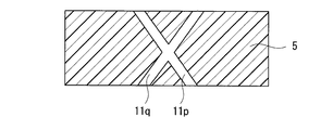
- the resin film 5 in which the through holes 11 having different directions extending at an inclination are mixed, two or more through holes 11 may intersect each other in the resin film 5. That is, the resin film 5 may have a set of through holes 11 that intersect with each other in the film 5. Such an example is shown in FIG. In the example shown in FIG. 7, the through holes 11 p and 11 q intersect with each other in the resin film 5.
- the direction in which the through hole 11 extends in the resin film 5 is, for example, by observing the main surface and cross section of the film 5 with a scanning electron microscope (SEM). I can confirm.
- the resin film 5 can have an air permeability of 10 cm 3 / (cm 2 ⁇ sec) or more in the thickness direction as indicated by the number of fragiles measured in accordance with JIS L1096.
- the air permeability in the thickness direction is within this range, the degree of freedom in designing various characteristics is higher in the mask 1 including the resin film 5 in the main body 2, for example, shielding property, air permeability, transparency, and throughness.
- the sound can be lined up at a higher level.
- the main surface 12b having a relatively large diameter of the through hole 11 is used.
- the air permeability of the resin film 5 to the main surface 12a having a relatively small diameter of the through-hole 11 can be in the above range as indicated by the Frazier number.
- Resin film 5 has little variation in air permeability.
- the ratio ⁇ / Av (breathability fluctuation rate ⁇ / Av) of the standard deviation ⁇ with respect to the average value Av of the fragile air permeability measured at any 40 points in the resin film 5 is 0.3 or less.
- the rate of change may be 0.2 or less, and further 0.1 or less.
- Nonwoven fabrics and woven fabrics cannot achieve such a low air permeability variation rate.
- a low air permeability variation rate contributes to a higher degree of freedom in designing various characteristics in the mask 1 including the resin film 5 in the main body 2, and improves the stability of the performance of the mask 1 and manufacture of the mask 1. It also contributes to improving yield.
- the variation in the density of the through holes 11 can be reduced.
- the density variation of the through holes 11 can be 1000 pieces / cm 2 or less. Even with such a small variation in density, the same effect as the small variation in air permeability can be obtained.
- the density variation of the through holes 11 can be 500 pieces / cm 2 or less.
- the variation in the density of the through holes 11 can be reduced.
- the variation in the density of the through-holes 11 is obtained by evaluating the density of the through-holes 11 at arbitrary five locations on the main surface of the resin film 5 to be evaluated, and calculating the ratio from the evaluated average value Av and standard deviation ⁇ . It can be obtained from ⁇ / Av.
- the openings of the plurality of through-holes 11 are spaced from each other on each main surface of the resin film 5. It can be formed independently. In other words, the openings of the different through holes 11 can be the resin films 5 in a state where they do not overlap on each main surface of the resin film 5. In such a resin film 5, the shape, diameter, density, and the like of the through holes 11 can be controlled with higher accuracy and uniformity. As a more specific example in this case, the through hole 11 can be formed at a position corresponding to the apex of the assumed grid on each main surface.
- the through-hole 11 can be formed relatively easily at a position corresponding to the assumed vertex of the lattice.
- the resin film 5 has less variation in the interval (pitch) between the openings and smaller variation in air permeability.
- the assumed lattice is not particularly limited, and is, for example, an orthorhombic lattice, a hexagonal lattice, a square lattice, a rectangular lattice, or a rhombus lattice.
- Each of the lattice meshes is a parallelogram, hexagon, square, rectangle, or rhombus (face-centered rectangle).
- FIG. 8 shows an example of such a resin film 5.
- the opening 14 of the through-hole 11 is formed in the position corresponding to the vertex of the square lattice assumed on the main surface.
- the openings of different through holes 11 may overlap each other on each main surface of the resin film 5.
- the through hole 11 is formed by ion beam irradiation and chemical etching on the original film, which will be described later, such a resin film 5 can be formed.
- the opening ratio of the resin film 5 (the ratio of the opening area of the through hole 11 in the main surface to the area of the main surface) is, for example, 50% or less, 5% or more and 45% or less, 10% or more and 45% or less, or It may be 20% or more and 40% or less.
- the aperture ratio can be obtained, for example, by analyzing an image obtained by observing the surface of the resin film 5 with a microscope.
- the through hole 11 in one main surface 12 a when the diameter of the through hole 11 in one main surface 12 a is different from the diameter of the through hole 11 in the other main surface 12 b, the main surface 12 a having a relatively small diameter of the through hole 11.
- the through hole 11 has a density variation and / or an aperture ratio in the above-described range.
- the porosity of the resin film 5 is, for example, 5% to 45% and can be 30% to 40%. When the porosity is within these ranges, the degree of freedom in designing various characteristics is higher in the mask 1 including the resin film 5 in the main body 2.
- the opening ratio and the porosity are the same. As shown in FIG.
- the porosity is, for example, both main surfaces It can obtain
- the apparent density can be obtained by dividing the weight W (g) of the resin film 5 cut into an arbitrary size by the volume V (cm 3 ).
- the resin film 5 may have a sound pressure loss (insertion loss) at a frequency of 1 kHz, for example, of 5 dB or less, and depending on the configuration of the resin film 5, the sound pressure loss at a frequency of 1 kHz may be 3 dB or less, 2 dB or less, Can be 1 dB or less. With nonwoven and woven fabrics, it is difficult to achieve such a low sound pressure loss.
- the frequency of 1 KHz corresponds to a frequency approximately in the center of the sound range (frequency range) that humans use for normal speech and conversation.
- the resin film 5 may have a total light transmittance of 60% or more measured according to JIS K7361, for example. Depending on the configuration of the resin film 5, the total light transmittance may be 70% or more. It may be 80% or more, and further 90% or more.
- the resin film 5 may have a haze of 50% or less measured according to JIS K7136, or 30% or less, and further 20% or less depending on the configuration of the resin film 5. sell.
- the thickness of the resin film 5 is, for example, 5 ⁇ m to 100 ⁇ m, and preferably 15 ⁇ m to 50 ⁇ m.
- the ratio t / R of the thickness t of the resin film 5 to the diameter R of the through hole 11 may be 1 or more and 10,000 or less. In this case, in the mask 1 including the resin film 5 in the main body 2. The degree of freedom in designing various characteristics becomes higher.
- the material constituting the resin film 5 is not particularly limited.
- it is a material that can form the through holes 11 in the original film that is a resin film.
- the resin film 5 and the material constituting the original film are selected from, for example, an alkaline solution, an acidic solution, an oxidizing agent, an organic solvent, and a surfactant.
- the resin is decomposed by an alkaline solution or an acidic solution to which at least one kind is added. These solutions are typical etching processing solutions.
- the resin film 5 and the original film are made of an etchable resin by hydrolysis or oxidative decomposition, for example.
- the resin film 5 and the original film are made of at least one resin selected from, for example, polyethylene terephthalate (PET), polycarbonate, polyimide, polyethylene naphthalate, and polyvinylidene fluoride.
- the resin film 5 and the material constituting the original film are, for example, polyolefins such as polyethylene and polypropylene, polyethylene terephthalate (PET), polybutylene terephthalate, and polyethylene naphthalate.
- Fluororesin such as polyester, polytetrafluoroethylene (PTFE), polyimide, polyamideimide, polyetheretherketone, polysulfone, polybutadiene, epoxy resin, polystyrene, polymethyl methacrylate, polycarbonate, triacetyl cellulose, polyvinyl alcohol, polyurethane, ABS resin, ethylene-propylene-diene copolymer, silicone rubber.
- the material constituting the resin film 5 and the original film is at least selected from, for example, PET, polypropylene, PTFE, polyimide, polymethyl methacrylate, polycarbonate, triacetyl cellulose, polyurethane, and silicone rubber. It is composed of one kind of resin.
- the resin film 5 and the original film are made of a transparent material, and more specific examples include PET, polycarbonate, polyimide, and polyethylene. It is preferably composed of at least one resin selected from phthalate and polyvinylidene fluoride.
- the resin film 5 may be subjected to various treatments such as a liquid repellent treatment, a coloring treatment, and an antifogging treatment.
- the invasion of splashes from the outside can be further suppressed, or the mask 1 further having waterproofness can be obtained.
- the liquid repellent treatment can be performed by a known method.
- a treatment liquid prepared by diluting a water repellent or a hydrophobic oil repellent with a diluent can be applied thinly on the resin film 5 and dried. . After the resin film 5 is immersed in the treatment liquid, it may be dried.
- the water repellent and the hydrophobic oil repellent are, for example, fluorine compounds such as perfluoroalkyl acrylate and perfluoroalkyl methacrylate.
- a liquid repellent layer can be formed on at least a part of the surface of the resin film 5.
- a liquid repellent layer may be formed on the entire surface of the resin film 5.
- the formed liquid repellent layer may have an opening at a position corresponding to the opening of the through hole 11.
- the mask 1 in which at least a part of the main body 2 is colored in a specific color can be obtained.
- An example of coloring is coloring to a color that does not make the wearer aware of blood even when blood is attached to the mask when a medical worker who is wearing the mask 1 treats a patient.
- the mask 1 in which the occurrence of fogging due to the breathing of the wearer is suppressed can be obtained.
- the antifogging treatment can be performed by a known method.
- the manufacturing method of the resin film 5 is not specifically limited, For example, it can manufacture with the manufacturing method demonstrated below.
- the resin film 5 is formed by ion beam irradiation and subsequent etching (chemical etching) on the original film.
- the resin film 5 formed by ion beam irradiation and etching may be used for the mask 1 as it is, or may be applied to the mask 1 through further processes such as a liquid repellent process, a coloring process or an antifogging process as necessary. May be used.
- the method of forming the resin film 5 by ion beam irradiation and subsequent chemical etching for example, it is easy to control the aperture ratio, porosity, air permeability, etc., as well as the diameter and density of the through-holes 11 of the resin film 5. Become.
- the original film may be a non-porous resin film that does not have a path that allows air to flow in the thickness direction in the region used as the resin film 5 after ion beam irradiation and chemical etching.
- the original film may be a non-porous film.
- the above-described coloring treatment may be applied to the original film.
- a colored resin film 5 is formed.
- This method of forming the resin film 5 from the original film may include a step (I) of irradiating the non-porous original film with an ion beam and a step (II) of chemically etching the original film irradiated with the ion beam. .
- step (I) a trajectory (ion track) of ion collision extending linearly penetrating in the thickness direction of the film is formed on the original film.
- through holes 11 corresponding to the ion tracks formed in the step (I) are formed in the original film by chemical etching, and the resin film 5 having air permeability in the thickness direction is formed.
- the resin film 5 having the through-hole 11 having a constant cross-sectional area from one main surface 12a to the other main surface 12b is also used in the one main surface 12a.
- the resin film 5 having the through-holes 11 that increase toward the other main surface 12b can also be formed.
- the former resin film 5 can be formed, for example, by directly etching the original film after ion irradiation. Since the region corresponding to the ion track formed in the original film is removed by etching, the through-hole 11 having a constant cross-sectional area is formed by taking sufficient chemical etching time.
- the latter resin film 5 is subjected to chemical etching in which the degree of etching of the part from one main surface is larger than the degree of etching of the part from the other main surface.
- chemical etching in which the degree of etching of the part from one main surface is larger than the degree of etching of the part from the other main surface.
- it can be formed by performing chemical etching in a state where a masking layer is disposed on one main surface of the original film after ion irradiation. In this chemical etching, the degree of etching from the other main surface is larger than that from the one main surface on which the masking layer is disposed.
- the cross-sectional area is reduced.
- the through-hole 11 having a shape that changes from one main surface of the resin film 5 toward the other main surface can be formed.
- the uniform etching proceeds from both main surfaces of the original film after the ion beam irradiation.
- steps (I) and (II) in the first production method will be described more specifically.
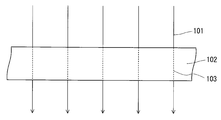
- step (I) the original film is irradiated with an ion beam.
- the ion beam is composed of accelerated ions.
- an original film in which ions in the beam collide is formed.
- the ions 101 in the beam collide with the original film 102, and the collided ions 101 leave a locus (ion track) 103 inside the film 102.
- the ions 101 When viewed on the size scale of the original film 102 that is the object to be irradiated, the ions 101 usually collide with the original film 102 in a substantially straight line, so that a linearly extending locus 103 is formed on the film 102.
- the ions 101 usually penetrate the original film 102.
- the method of irradiating the original film 102 with an ion beam is not limited.
- the ions 101 are generated from the beam line. Irradiate the film 102.
- a specific gas may be added to the chamber, or the original film 102 may be accommodated in the chamber, but the pressure in the chamber may not be reduced, and for example, ion beam irradiation may be performed at atmospheric pressure.
- a roll around which the belt-like original film 102 is wound may be prepared, and the original film 102 may be continuously irradiated with the ion beam while the original film 102 is fed out from the roll. Thereby, the resin film 5 can be formed efficiently.
- the roll (delivery roll) and the take-up roll that winds up the original film 102 after irradiation with the ion beam are arranged in the chamber described above, and the belt is formed in a strip shape from the delivery roll in an arbitrary atmosphere such as reduced pressure or high vacuum. While the original film 102 is being fed out, the film may be continuously irradiated with an ion beam, and the original film 102 after the beam irradiation may be taken up on a take-up roll.
- the resin constituting the original film 102 is the same as the resin constituting the resin film 5.
- the original film 102 irradiated with the ion beam is, for example, a non-porous film.
- a resin other than the through-holes 11 formed by the steps (I) and (II) is non-porous unless a further step of forming holes in the film is performed.
- Film 5 can be formed.
- the type of ions 101 irradiated and collided with the original film 102 is not limited, but the chemical reaction with the resin constituting the original film 102 is suppressed, so that ions having a mass number larger than neon, specifically argon. At least one ion selected from ions, krypton ions and xenon ions is preferred.
- the energy (acceleration energy) of the ions 101 is typically 100 to 1000 MeV.
- the energy of the ions 101 when the ion species is argon ions is preferably 100 to 600 MeV.
- the energy of the ions 101 irradiated to the original film 102 can be adjusted according to the ion species and the type of resin constituting the original film 102.
- the ion source of the ions 101 irradiated to the original film 102 is not limited.
- the ions 101 emitted from the ion source are accelerated by an ion accelerator and then irradiated to the original film 102 through a beam line.
- the ion accelerator is, for example, a cyclotron, and a more specific example is an AVF cyclotron.
- the pressure of the beam line serving as the path of the ions 101 is preferably a high vacuum of about 10 ⁇ 5 to 10 ⁇ 3 Pa from the viewpoint of suppressing energy attenuation of the ions 101 in the beam line.
- the pressure difference between the beam line and the chamber may be maintained by a partition wall that transmits the ions 101.
- the partition is made of, for example, a titanium film or an aluminum film.
- the ions 101 are irradiated to the film from a direction perpendicular to the main surface of the original film 102, for example. In the example shown in FIG. 9, such irradiation is performed. In this case, since the trajectory 103 extends perpendicularly to the main surface of the original film 102, the resin film 5 in which the through holes 11 extending in the direction perpendicular to the main surface are formed is obtained by subsequent chemical etching.
- the ions 101 may irradiate the film from a direction oblique to the main surface of the original film 102. In this case, the resin film 5 in which the through hole 11 extending in the direction inclined from the direction perpendicular to the main surface is formed by subsequent chemical etching.
- the direction in which the original film 102 is irradiated with the ions 101 can be controlled by a known means.
- the angle ⁇ 1 in FIG. 4 can be controlled by, for example, the incident angle of the ion beam with respect to the original film 102.
- the ions 101 are irradiated on the original film 102 so that, for example, tracks of the plurality of ions 101 are parallel to each other. In the example shown in FIG. 9, such irradiation is performed. In this case, the resin film 5 in which the plurality of through holes 11 extending in parallel with each other is formed by the subsequent chemical etching.
- the ions 101 may be irradiated to the original film 102 so that tracks of the plurality of ions 101 are not parallel to each other (for example, are random to each other). Thereby, for example, a resin film 5 as shown in FIGS. 4 to 7 is formed. More specifically, in order to form the resin film 5 as shown in FIGS. 4 to 7, for example, the ion beam is irradiated while being tilted from a direction perpendicular to the main surface of the original film 102 and continuously or stepwise. The tilt direction may be changed.
- the ion beam is a beam in which a plurality of ions fly in parallel with each other, a set of through holes 11 extending in the same direction is usually present in the resin film 5 (the plurality of through holes 11 extending in the same direction are resin films). 5).
- FIG. 10 shows an example of a method for changing the tilt direction continuously or stepwise.
- the belt-shaped original film 102 is sent out from the delivery roll 105, passed through the irradiation roll 106 having a predetermined curvature, irradiated with the ion beam 104 while passing through the roll 106, and the original after irradiation.
- the film 102 is taken up on a take-up roll 107.
- the ions 101 in the ion beam 104 fly one after another in parallel, the angle at which the original film 102 moves on the irradiation roll 106 and the ion beam collides with the main surface of the original film 102 ( The incident angle ⁇ 1) will change.
- the tilt direction changes continuously, and if the ion beam 104 is intermittently irradiated, the tilt direction changes stepwise. This can be said to be control by the irradiation timing of the ion beam.
- the state of the trajectory 103 formed on the original film 102 (for example, the angle ⁇ 1) can also be controlled by the cross-sectional shape of the ion beam 104 and the cross-sectional area of the beam line of the ion beam 104 with respect to the irradiation surface of the original film 102.
- the hole density of the resin film 5 can be controlled by the irradiation conditions (ion species, ion energy, ion collision density (irradiation density), etc.) of the original film 102 with the ion beam.
- irradiation conditions ion species, ion energy, ion collision density (irradiation density), etc.
- the ions 101 may be irradiated to the original film 102 from two or more beam lines.
- Step (I) may be performed in a state where the masking layer is disposed on the main surface of the original film 102, for example, the one main surface.
- the masking layer can be used as a masking layer in the step (II).
- Step (II) In the step (II), the portion of the original film 102 that has been irradiated with the ion beam in the step (I) is subjected to chemical etching, so that the through-hole 11 extending along the trajectory 103 of the collision of the ions 101 Form into a film.
- the portions other than the through-holes 11 in the resin film 5 thus obtained are basically the same as the original film 102 before the ion beam irradiation unless a step of changing the state of the film is further performed.
- the specific etching method may follow a known method.
- the original film 102 after the ion beam irradiation may be immersed in the etching treatment liquid at a predetermined temperature and for a predetermined time.
- the diameter of the through hole 11 can be controlled by the etching conditions such as the etching temperature, the etching time, and the composition of the etching treatment liquid.
- Etching temperature is, for example, 40 to 150 ° C.
- etching time is, for example, 10 seconds to 60 minutes.
- Etching solution used for chemical etching is not particularly limited.
- the etching solution is, for example, an alkaline solution, an acidic solution, or an alkaline solution or an acidic solution to which at least one selected from an oxidizing agent, an organic solvent, and a surfactant is added.
- the alkaline solution is, for example, a solution (typically an aqueous solution) containing a base such as sodium hydroxide or potassium hydroxide.
- the acidic solution is, for example, a solution (typically an aqueous solution) containing an acid such as nitric acid or sulfuric acid.
- the oxidizing agent include potassium dichromate, potassium permanganate, and sodium hypochlorite.
- the organic solvent is, for example, methanol, ethanol, 2-propanol, ethylene glycol, amino alcohol, N-methylpyrrolidone, or N, N-dimethylformamide.
- the surfactant is, for example, an alkyl benzene sulfonate or an alkyl sulfate.
- the chemical etching may be performed in a state where a masking layer is disposed on one main surface of the original film 102 after irradiation with the ion beam.
- the etching of the portion of the original film 102 where the ions 101 collide is greater in the degree of etching from the other main surface than in the etching from the one main surface where the masking layer is disposed. That is, chemical etching (asymmetric etching) in which etching from both principal surfaces of the film proceeds asymmetrically is performed on the portion of the original film 102 where the ions 101 collide.
- “the degree of etching is large” means, for example, that the etching amount per unit time is large for the part, that is, the etching rate is high for the part.
- the above-mentioned portion from the one main surface is arranged on the one main surface of the original film 102 by disposing a masking layer that is hard to be chemically etched compared to the portion where the ions 101 collide with the original film 102.
- Such etching can be performed, for example, by selecting the type and thickness of the masking layer, disposing the masking layer, selecting etching conditions, and the like.
- the type of the masking layer is not particularly limited, but is preferably a layer made of a material that is difficult to chemically etch compared to the portion of the original film 102 where the ions 101 collide. More specifically, “not easily etched” means, for example, that the amount etched per unit time is small, that is, the etching rate is small. Whether or not chemical etching is difficult can be determined based on the conditions of the asymmetric etching actually performed in the step (II) (the type of etching solution, etching temperature, etching time, etc.). In the case of performing a plurality of asymmetric etchings in the step (II) while changing the type and / or arrangement surface of the masking layer, each etching may be determined based on the etching conditions.
- the masking layer may be easy to be chemically etched or difficult to etch than the portion of the original film 102 where the ions 101 do not collide, but it is preferable that the masking layer is difficult to do. If it is difficult to do so, for example, the thickness of the masking layer required to perform asymmetric etching can be reduced.
- step (I) when the original film 102 on which the masking layer is arranged is irradiated with an ion beam, an ion track is also formed on the masking layer.
- the material constituting the masking layer is a material in which the polymer chain is hardly damaged even by irradiation with an ion beam.
- the masking layer is composed of at least one selected from, for example, polyolefin, polystyrene, polyvinyl chloride, polyvinyl alcohol, and metal foil. These materials are difficult to be chemically etched and are not easily damaged by ion beam irradiation.
- the masking layer When the masking layer is disposed and asymmetric etching is performed, the masking layer may be disposed on at least a part of one main surface of the original film 102 corresponding to a region where the etching is performed. As needed, it can arrange
- the method of disposing the masking layer on the main surface of the original film 102 is not limited as long as the masking layer does not peel off from the main surface during the asymmetric etching.
- the masking layer is disposed on the main surface of the original film 102 with an adhesive, for example. That is, in the step (II), the chemical etching (asymmetric etching) may be performed in a state where the masking layer is bonded to the one main surface with an adhesive.
- the arrangement of the masking layer with the pressure-sensitive adhesive can be performed relatively easily. Further, by selecting the type of pressure-sensitive adhesive, the masking layer can be easily peeled off from the original film 102 after asymmetric etching.
- the etching may be performed a plurality of times.
- symmetric etching in which the etching of the trajectory 103 progresses equally from both main surfaces of the original film 102 may be performed together.
- the asymmetric etching may be switched to the symmetric etching by peeling the masking layer from the original film 102 during the etching.
- the asymmetric etching may be performed by arranging a masking layer on the original film 102 after performing the symmetric etching.
- a part or all of the masking layer after the etching can be left on the resin film 5 as necessary.
- the remaining masking layer can be used, for example, as a mark for distinguishing between the one main surface (the main surface on which the masking layer is disposed) and the other main surface of the resin film 5.
- the etching conditions may be changed in each etching.
- the first manufacturing method may include any step other than steps (I) and (II).
- the resin film 5 is formed by forming a plurality of through holes 11 in the original film by irradiating the original film with laser.
- the resin film 5 having a plurality of through-holes 11 formed by laser irradiation may be used for the mask 1 as it is, and further steps such as a liquid repellent treatment step, a coloring treatment step or an anti-fogging treatment step as necessary. After that, the mask 1 may be used.
- the method of forming the resin film 5 by laser irradiation for example, it is easy to control the aperture ratio, the porosity, the air permeability, and the like as well as the diameter and density of the through holes 11 of the resin film 5.
- the original film may be a non-porous resin film that does not have a path that allows ventilation in the thickness direction in the region used as the resin film 5.
- the original film may be a non-porous film.
- the same material as that constituting the resin film 5 to be obtained can be selected as the material constituting the original film.
- the thickness of the film does not change by the laser irradiation for forming the through-hole 11. For this reason, the thickness of the resin film 5 to be obtained can be selected as the thickness of the original film.
- the original film is irradiated with, for example, a focused pulse laser.
- a known laser and optical system can be used for the focused pulse laser.
- the laser is, for example, a UV pulse laser, and examples of wavelengths thereof are 355 nm, 349 nm, and 266 nm (high-order harmonics of solid lasers using Nd: YAG, Nd: YLF, or YVO 4 as a medium), 351 nm, 248 nm, and 222 nm. 193 nm or 157 nm (excimer laser).
- a laser having a wavelength region other than UV may be used.
- the pulse width of the laser is not limited as long as the through-hole 11 can be formed.
- a pulse laser having a pulse width on the order of femtosecond or picosecond can be used.
- the through holes 11 are formed by ablation based on a multiphoton absorption process.
- the spatial intensity distribution of the laser beam may be a Gaussian distribution having a high center intensity, or may be a top hat distribution having a uniform distribution.
- the optical system includes, for example, a galvano scanner and an F ⁇ lens (condensing lens).
- the F ⁇ lens is preferably selected and placed in the optical system so that the telecentricity is within 5 degrees.
- the optical system can also include a polygon mirror scanner. An optical system including these scanners makes it easier to form the through hole 11 at a target position on the original film.
- an assist gas is sprayed on or near the processing portion, or the processing portion Or measures such as inhaling the vicinity thereof may be taken.
- an assist gas such as nitrogen, air, oxygen, or the like can be used. Spraying and suction may be combined.
- the thickness of the original film is preferably 5 ⁇ m or more and 50 ⁇ m or less.
- the thickness of the original film is within this range, the formation of the through holes 11 by laser irradiation can be performed more efficiently.
- the laser irradiation of the original film may be performed while fixing or moving the original film cut into a predetermined size, or may be performed while moving the belt-shaped original film.
- the belt-shaped original film wound around the roll may be fed out from the roll, the laser may be irradiated while moving the fed-out belt-shaped original film, and the film after laser irradiation may be wound around the roll. That is, the belt-shaped original film may be irradiated with a laser by roll-to-roll.
- the laser irradiation of the original film is carried out so that the laser beam is irradiated to the original film in a hollow state from the viewpoint of efficiently removing the decomposition residue of the material constituting the original film generated by the laser irradiation. May be.
- a suction mechanism for efficiently collecting and removing the decomposed material can be appropriately disposed on the back side of the original film (the side opposite to the side irradiated with the laser).
- the film is removed for the purpose of removing deposits on the film, for example, decomposition residues of materials constituting the original film, if necessary. You may wash.
- the cleaning method is not limited, and can be selected from, for example, immersion in water, wet cleaning using a shower and / or ultrasonic waves, or dry cleaning using plasma, UV ozone, ultrasonic waves, brushes, adhesive tapes, and the like. When wet cleaning is selected, a drying step may be further performed as necessary.
- the above-described coloring treatment may be applied to the original film.
- a colored resin film 5 is formed.
- the above-described liquid repellent treatment may be applied to the original film.
- the resin film 5 subjected to the liquid repellent treatment can be formed.
- the second manufacturing method may include any process other than the processes described above.
- the configuration of the mask of the present invention is not limited as long as it has a main body portion that covers at least a part of the face of the wearer, typically the nostril and mouth of the wearer, and includes the resin film 5. Except that the main body portion includes the resin film 5, the mask of the present invention can have the same configuration as a known mask.
- the mask of the present invention can include a locking portion 3 for fixing the main body portion 2 including the resin film 5 to the face of the wearer, like the mask 1 shown in FIG.
- the main body portion may be composed only of the resin film 5 or may be composed of the resin film 5 and other members, the wearer 51 can more reliably ensure the breathing, and the wearer can speak. Is easily transmitted to the outside (improving sound permeability as the mask 1), that is, it is possible to achieve a higher level of shielding, breathability and sound permeability, so that at least the portion covering the mouth of the wearer, preferably the nostril
- the portion covering the mouth is preferably composed of the resin film 5.
- the resin film 5 has transparency
- a portion of the main body 2 that requires transparency may be configured by the resin film 5
- the entire main body 2 is configured by a transparent resin film. You can also.
- the main body 2 has a shape that covers at least part of the face of the wearer of the mask 1, typically the nostril and mouth of the wearer.
- the mask 1 of the present invention may have a shape that covers all of the face of the wearer of the mask 1 considering that, for example, good shielding properties, air permeability, transparency, and sound permeability can be arranged side by side.
- the transparent main body 2 has a shape that covers the entire face of the wearer, and a portion that covers a part of the face of the wearer, typically the nostril and mouth of the wearer, is constituted by the resin film 5. It may be.
- the main body portion 2 has a pleated shape, and may have a shape in which the pleat is unfolded when the wearer correctly wears the mask 1, or a flat plate shape or a curved plate shape. May be.
- the hardness of the body 2 follows the shape of the face of the wearer 1. It can be changed from a flexible state to a rigid state in which the shape does not change even when worn.
- a part or the whole of the main body part 2 including the resin film 5 may be colorless and transparent or may be colored, and the resin film 5 and / or a part other than the resin film 5 in the main body part 2 may be colored and Transparent or colored and opaque materials may be used.
- a polyimide film is usually transparent and colored (orange).
- the mask 1 including the main body 2 and the main body 2 has a high degree of freedom in designing various characteristics including shielding, air permeability, transparency, and sound permeability.
- various variations can be made in the configuration (shape, structure, hardness, etc.).
- Processing including liquid repellent treatment, anti-fogging treatment, and printing may be performed on a part or the whole of the main body 2 including the resin film 5.
- the liquid repellent treatment and the antifogging treatment are as described above in the description of the resin film 5.
- the specific state and method of printing are not limited. Unlike the main body portion composed of non-woven fabric and woven fabric, more free printing is possible.
- the medical mask in addition to improving the communication between the medical staff and the patient because the main body 2 is transparent, the medical staff engages in the medical treatment by using the main body 2 with the animal face printed for a child patient. It is also possible to improve communication between a person and a patient.
- printing of a member that can confirm whether or not the mask 1 has been used printing of a member that can check the contamination status of the mask 1, serial number, ID number, owner's affiliation and name printing, IC chip, GPS
- Various printing on the main body 2 including the resin film 5 is possible, such as printing of electronic elements such as chips and printing of electronic circuits such as antennas, microphones, and earphones.
- the mask 1 may be disposable or reusable.
- the mask 1 can have any member other than the main body 2.
- the example of the said member is the latching
- locking part 3 is not limited, What is necessary is just the same as the latching
- the locking portion 3 in the example shown in FIG. 1 is a string-like member that is put on the wearer's auricle.
- the locking portion 3 can be, for example, a tape, a wire, a ribbon, or the like that fixes the main body portion 2 at the position of the wearer's nose.
- the method for joining the locking portion 3 and the main body portion 2 is not limited, and the position of the locking portion 3 in the mask 1 and the position and method for joining the locking portion 3 and the main body portion 2 are not limited.
- the breathability (breathability in the thickness direction) of the resin film 5 and the main body of the conventional mask was determined in accordance with the Frazier permeability test specified in JIS L1096.
- the resin film 5 and the main body of the conventional mask were each cut into a size of 100 mm ⁇ 100 mm to obtain a measurement sample.
- Case 91 (made of acrylic resin, length 70 mm ⁇ width 50 mm ⁇ height 15 mm) having a rectangular parallelepiped shape and a hollow inside was prepared.
- Case 91 has no opening except that one opening 92 having a diameter of 13 mm is provided on the upper surface of case 91.
- the resin film 5 to be evaluated and the main body of the conventional mask were punched into a circle having a diameter of 16 mm to prepare a measurement sample.
- a measurement sample 93 was attached using a ring-shaped double-sided tape 94 having an outer diameter of 16 mm and an inner diameter of 13 mm so as to completely cover the opening 92 from the inside of the case 91.
- the double-sided tape 94 did not protrude from the opening 92, and no gap was generated between the inner surface of the case 91 and the measurement sample 93.
- the speaker 95 was affixed to the measurement sample 93 using the same double-sided tape. Also at this time, no gap was created between the measurement sample 93 and the speaker 95.
- SCG-16A made by Star Seimitsu was used for the speaker.
- the microphone (B & K, Type 2669) connected to the acoustic evaluation device (B & K, Multi-analyzer System 3560-B-030) was placed outside the case 91 and 50 mm away from the speaker 95.
- SSR analysis test signal 20 Hz to 20 kHz, sweep up
- TDD sound pressure loss
- the sound pressure loss of the blank is obtained in the same manner except that the measurement sample 93 is not arranged in the opening 92, and the sound pressure loss of the blank is subtracted from the sound pressure loss when the measurement sample 93 is arranged.
- the sound pressure loss (insertion loss), which is a characteristic of the sample. It can be determined that the smaller the insertion loss, the better the characteristics of the sound transmitted through the measurement sample 93.
- the sound permeability of the measurement sample was evaluated by sound pressure loss at a frequency of 1 kHz.
- the shielding properties of the resin film 5 produced in Example 1 and the conventional mask used in Comparative Example 1 were evaluated as pollen permeability based on a pollen permeability test according to Boken Standard BQE A 030. Specifically, it is as follows. First, a glass filter and black filter paper that does not pass pollen were set in a glass holder (inner diameter: about 2 cm) having a cylindrical shape that can be sucked from below, and a measurement sample was placed thereon. The measurement sample was obtained by cutting the resin film 5 and the main body of the conventional mask into shapes and sizes (circular shapes having a diameter of about 2 cm) that can be accommodated in the holders.
- 0.05 g of cedar pollen is uniformly deposited on the measurement sample, and the flow rate is 12 L / min (corresponding to the average inspiratory flow rate of breathing when a person is resting) with a suction pump connected to the lower part of the holder. Aspirated for 1 minute. By this suction, air passes through the pollen, the measurement sample, the black filter paper, and the glass filter in order, so that the pollen that has passed through the measurement sample is collected by the filter paper.
- Example 1 As the resin film 5, a non-porous PET film (made by Oxyphen, Oxydisk) having a plurality of through holes extending in the thickness direction was prepared.
- This film is a film in which a plurality of through holes extending in a direction perpendicular to the main surface of the film are formed by performing ion beam irradiation and chemical etching on a non-porous original film made of PET.
- the diameter of the through hole was 10 ⁇ m
- the density of the through hole was 500,000 (5 ⁇ 10 5 ) pieces / cm 2
- the aperture ratio and the porosity were 31.4%
- the thickness was 41 ⁇ m.
- the prepared resin film 5 is cut out into a rectangular shape having a size of 180 mm ⁇ 160 mm, and further folded into a pleat to form a rectangular shape having a size of 80 mm ⁇ 160 mm.
- a string-like member for placing on the auricle was fixed with double-sided tape.
- a mask 1 as shown in FIG. 12 was obtained.
- the produced mask 1 was able to be worn so as to cover the nostril and mouth of the face in the same manner as a conventional non-woven fabric mask (for example, the mask used in Comparative Example 1).
- Example 2 Example of the resin film 5 except that the diameter of the through holes is 5 ⁇ m, the density of the through holes is 400,000 (4 ⁇ 10 5 ) pieces / cm 2 , the aperture ratio and the porosity are 7.9%, and the thickness is 21 ⁇ m.
- a film similar to the resin film 5 prepared in 1 was prepared.
- a mask 1 was produced using the prepared resin film in the same manner as in Example 1. The produced mask 1 was similar to a conventional non-woven fabric mask (for example, the mask used in Comparative Example 1), and the nostrils and mouth of the face. It was able to be installed to cover.
- Example 3 Example of resin film 5 except that the diameter of the through holes is 2 ⁇ m, the density of the through holes is 10000000 (1 ⁇ 10 7 ) pieces / cm 2 , the opening ratio and the porosity are 39.2%, and the thickness is 21 ⁇ m.
- a film similar to the resin film 5 prepared in 1 was prepared.
- a mask 1 was produced using the prepared resin film in the same manner as in Example 1. The produced mask 1 was similar to a conventional non-woven fabric mask (for example, the mask used in Comparative Example 1), and the nostrils and mouth of the face. It was able to be installed to cover.
- Example 4 As the resin film 5, the non-porous PET film used in Example 1 was prepared.
- the treatment liquid used for the liquid repellent treatment of the prepared resin film 5 is a diluent of water and oil repellent (X-70-041 manufactured by Shin-Etsu Chemical Co., Ltd.) so as to have a concentration of 1.0% by weight. (Asahi Kurain AE-3000, manufactured by Asahi Glass) and diluted.
- This water / oil repellent comprises a polymer having a unit derived from a monomer having a linear fluoroalkyl group represented by the following formula (a-1).
- CH 2 CHCOOCH 2 CH 2 C 5 F 10 CH 2 C 4 F 9 (a-1)
- the prepared resin film 5 was dipped in a water / oil repellent maintained at 20 ° C. for 3 seconds and then left to dry at room temperature for 1 hour to obtain a liquid-repellent treated resin film 5.
- a mask 1 was produced using the obtained resin film 5 in the same manner as in Example 1. However, the produced mask 1 was similar to a conventional nonwoven fabric mask (for example, the mask used in Comparative Example 1). It could be worn to cover the nostril and mouth of the face.
- Comparative Example 1 As a mask for Comparative Example 1, a mask (FG-195 ⁇ , manufactured by Tokyo Medical) having a main body portion composed of a nonwoven fabric was prepared.
- Comparative Example 2 As a mask for Comparative Example 2, a mask (3M, V-flex dustproof mask 9102J-DS1) having a main body portion made of a nonwoven fabric was prepared.
- Comparative Example 3 As a mask of Comparative Example 3, a mask (manufactured by Midori Safety Co., Ltd., Smile Catch Mask) in which the main body portion was composed of a non-porous transparent film was prepared.
- Example 1 The evaluation results of Examples 1 to 3 and Comparative Examples 1 to 3 are shown in Table 1 below. Moreover, as an evaluation result of the shielding properties for Example 1 and Comparative Example 1, the degree of pollen adhesion on the black filter paper surface after the test is shown in FIG.
- the degree of freedom of design was confirmed with respect to air permeability, sound permeability, transparency and shielding properties, and these characteristics were arranged side by side at a high level. It was confirmed that the mask was realized. More specifically, the mask produced in Example 1 has a high air permeability and is easy for the wearer to breathe, and has a high total light transmittance and a low haze, so that the face of the wearer can be sufficiently confirmed. . Further, the mask of Example 1 has an insertion loss of 0 dB, and exhibits excellent sound permeability without deteriorating the wearer's voice. It also has excellent pollen shielding ability.
- Example 4 a liquid-repellent-treated mask could also be manufactured.
- the mask of Comparative Example 1 has a very high air permeability, it is inferior in shielding properties and has a high haze, so it is difficult to confirm the face of the wearer.
- the mask of Comparative Example 2 has low haze and high transparency, it can be seen that the insertion loss is very large and the sound permeability is low.
- the mask of the present invention can be used for various purposes including the same use as the conventional mask.
Abstract
Priority Applications (4)
| Application Number | Priority Date | Filing Date | Title |
|---|---|---|---|
| EP16802795.1A EP3305114B1 (fr) | 2015-06-04 | 2016-05-27 | Masque |
| US15/576,978 US11517057B2 (en) | 2015-06-04 | 2016-05-27 | Mask |
| CN201680032572.5A CN107613800B (zh) | 2015-06-04 | 2016-05-27 | 口罩 |
| KR1020177035598A KR20180015656A (ko) | 2015-06-04 | 2016-05-27 | 마스크 |
Applications Claiming Priority (2)
| Application Number | Priority Date | Filing Date | Title |
|---|---|---|---|
| JP2015114118 | 2015-06-04 | ||
| JP2015-114118 | 2015-06-04 |
Publications (1)
| Publication Number | Publication Date |
|---|---|
| WO2016194353A1 true WO2016194353A1 (fr) | 2016-12-08 |
Family
ID=57440917
Family Applications (1)
| Application Number | Title | Priority Date | Filing Date |
|---|---|---|---|
| PCT/JP2016/002595 WO2016194353A1 (fr) | 2015-06-04 | 2016-05-27 | Masque |
Country Status (7)
| Country | Link |
|---|---|
| US (1) | US11517057B2 (fr) |
| EP (1) | EP3305114B1 (fr) |
| JP (1) | JP6696832B2 (fr) |
| KR (1) | KR20180015656A (fr) |
| CN (1) | CN107613800B (fr) |
| TW (1) | TWI676431B (fr) |
| WO (1) | WO2016194353A1 (fr) |
Families Citing this family (22)
| Publication number | Priority date | Publication date | Assignee | Title |
|---|---|---|---|---|
| KR102029132B1 (ko) * | 2017-06-09 | 2019-10-10 | (주)도움라이프 | 마우스피스형 마스크 |
| WO2019046434A1 (fr) * | 2017-09-01 | 2019-03-07 | ClearMask, LLC | Masque facial ayant une pièce en plastique transparent |
| JP2019206773A (ja) * | 2018-05-29 | 2019-12-05 | 株式会社イノアックコーポレーション | フィルタおよびこれを用いたマスク |
| JP7449647B2 (ja) * | 2019-01-30 | 2024-03-14 | デクセリアルズ株式会社 | 粒子充填シートの製造方法 |
| TWI683685B (zh) * | 2019-05-13 | 2020-02-01 | 江國慶 | 口罩 |
| US11565615B2 (en) * | 2020-04-28 | 2023-01-31 | Global Ip Holdings, Llc | Anti-microbial, partition divider assembly for a cart such as a golf cart |
| BE1028256B1 (nl) * | 2020-05-04 | 2021-12-07 | Wim Paul Modest Vanlommel | Mondmasker |
| JP6831957B1 (ja) * | 2020-06-23 | 2021-02-24 | 有限会社サンエイダイテクス | マスクシート及びマスクシート装着フレーム |
| JP7270259B2 (ja) * | 2020-06-24 | 2023-05-10 | 株式会社earch | 理美容用マスク |
| JP2022012531A (ja) * | 2020-07-01 | 2022-01-17 | 浜口ウレタン株式会社 | マスク |
| KR102473899B1 (ko) * | 2020-08-10 | 2022-12-06 | 조성진 | 투명 나노 공기순환 통풍구조의 필터 착탈형 기능성 마스크 |
| KR102234802B1 (ko) * | 2020-09-02 | 2021-04-01 | 선영화학 주식회사 | 무독성 착색마스크 및 그의 제조방법 |
| TWI739591B (zh) * | 2020-09-09 | 2021-09-11 | 淡江大學 | 微流道矽膠口罩 |
| KR102260045B1 (ko) * | 2020-09-24 | 2021-06-03 | 전서연 | 밀착력이 향상된 투명 마스크 |
| US20220105369A1 (en) * | 2020-10-06 | 2022-04-07 | Kristine Erive Lee | Adjustable facemask |
| US20220117331A1 (en) * | 2020-10-15 | 2022-04-21 | Raytheon Company | Augmented face mask |
| US20220192288A1 (en) * | 2020-12-21 | 2022-06-23 | International Business Machines Corporation | Contextual personal protective equipment |
| JP7350710B2 (ja) * | 2020-12-28 | 2023-09-26 | ユニ・チャーム株式会社 | マスク |
| KR102584818B1 (ko) * | 2021-01-14 | 2023-10-10 | 부산대학교 산학협력단 | 나노 그래핀 필터 |
| KR102276785B1 (ko) * | 2021-01-21 | 2021-07-13 | 뭄무컴퍼니 | 마스크 면적 조절을 위한 마스크 집게 |
| IL280523B2 (en) | 2021-01-31 | 2023-08-01 | Sion Biotext Medical Ltd | A filter element and its uses |
| WO2022230585A1 (fr) * | 2021-04-27 | 2022-11-03 | ユニ・チャーム株式会社 | Masque |
Citations (3)
| Publication number | Priority date | Publication date | Assignee | Title |
|---|---|---|---|---|
| JPS6017760U (ja) * | 1983-07-15 | 1985-02-06 | ジヤパンゴアテツクス株式会社 | マスク |
| JP2004351190A (ja) * | 2002-08-21 | 2004-12-16 | Daiya Seiyaku Kk | マスク及びその製造方法 |
| JP2007014576A (ja) * | 2005-07-08 | 2007-01-25 | Daio Paper Corp | マスク |
Family Cites Families (26)
| Publication number | Priority date | Publication date | Assignee | Title |
|---|---|---|---|---|
| US3042034A (en) * | 1958-04-21 | 1962-07-03 | Lou A Gruenewaelder | Face masks |
| US4004584A (en) * | 1975-07-28 | 1977-01-25 | Alleraid Company, Inc. | Facially-worn breathing filter |
| US4467799A (en) * | 1980-05-05 | 1984-08-28 | Steinberg Jacob H | Transparent odor-free face mask |
| JPS6017760A (ja) | 1983-07-12 | 1985-01-29 | Ricoh Co Ltd | 電子写真製版用印刷版 |
| FR2607022B1 (fr) * | 1986-11-20 | 1991-02-22 | Commissariat Energie Atomique | Realisation de membranes microporeuses asymetriques par double irradiation, et membranes ainsi obtenues |
| US5863312A (en) * | 1992-10-23 | 1999-01-26 | Wolfe; Michael | Non-entraining filter |
| JP2825758B2 (ja) * | 1994-06-03 | 1998-11-18 | クリンテック株式会社 | 鼻部保温マスク |
| JPH10211294A (ja) | 1997-01-29 | 1998-08-11 | Toppan Printing Co Ltd | 芳香マスク |
| TW592746B (en) * | 2003-05-09 | 2004-06-21 | Ming-Jeng Shiu | Mask |
| KR100514662B1 (ko) * | 2003-05-19 | 2005-09-16 | 이시원 | 안면 마스크 |
| TWM258750U (en) * | 2003-07-11 | 2005-03-11 | Ct Healthcare Technology Co Lt | Structure of mask |
| JP4684318B2 (ja) * | 2005-02-01 | 2011-05-18 | 株式会社ボックス | マスク |
| EP1953286A1 (fr) * | 2007-02-01 | 2008-08-06 | Nisshinbo Industries, Inc. | Tissu et masque |
| EP2114534A4 (fr) * | 2007-03-02 | 2011-02-16 | Puckett Anne Mcintosh | Masque facial antimicrobien transparent |
| JP2009011475A (ja) | 2007-07-03 | 2009-01-22 | Netmelon Inc | 透明マスク |
| US20090044809A1 (en) * | 2007-08-16 | 2009-02-19 | Kimberly-Clark Worldwide, Inc. | Vent and strap fastening system for a disposable respirator |
| CN201328385Y (zh) | 2008-11-20 | 2009-10-21 | 龙邓宇 | 一种防护面具 |
| US20110296584A1 (en) * | 2010-06-03 | 2011-12-08 | Chin-Feng Kuo | Mask that Provides a Comfortable Sensation to a User |
| US20120167891A1 (en) * | 2011-01-03 | 2012-07-05 | John Smaller | Adjustable facial conforming face mask |
| JP5896373B2 (ja) | 2011-08-28 | 2016-03-30 | ネットメロン有限会社 | 透明マスク |
| JP2013066643A (ja) | 2011-09-26 | 2013-04-18 | Bio Design Kk | 透視可能な衛生マスク |
| CN202800200U (zh) * | 2012-06-07 | 2013-03-20 | 陈泽彬 | 保暖遮光面罩 |
| CN202958898U (zh) | 2012-12-17 | 2013-06-05 | 于丽 | 透气口罩 |
| JP6474977B2 (ja) * | 2013-08-30 | 2019-02-27 | 日東電工株式会社 | 防水通気膜とそれを備える防水通気部材および防水通気構造ならびに防水通音膜 |
| CN104432701A (zh) | 2013-09-18 | 2015-03-25 | 封正合 | 便捷式口罩 |
| KR20170095209A (ko) * | 2014-11-12 | 2017-08-22 | 필리스 쿤 | 살균성 금속 또는 살균성 금속합금 마스크 |
-
2016
- 2016-05-27 US US15/576,978 patent/US11517057B2/en active Active
- 2016-05-27 KR KR1020177035598A patent/KR20180015656A/ko not_active Application Discontinuation
- 2016-05-27 CN CN201680032572.5A patent/CN107613800B/zh active Active
- 2016-05-27 WO PCT/JP2016/002595 patent/WO2016194353A1/fr active Application Filing
- 2016-05-27 JP JP2016106616A patent/JP6696832B2/ja active Active
- 2016-05-27 EP EP16802795.1A patent/EP3305114B1/fr active Active
- 2016-05-30 TW TW105116865A patent/TWI676431B/zh active
Patent Citations (3)
| Publication number | Priority date | Publication date | Assignee | Title |
|---|---|---|---|---|
| JPS6017760U (ja) * | 1983-07-15 | 1985-02-06 | ジヤパンゴアテツクス株式会社 | マスク |
| JP2004351190A (ja) * | 2002-08-21 | 2004-12-16 | Daiya Seiyaku Kk | マスク及びその製造方法 |
| JP2007014576A (ja) * | 2005-07-08 | 2007-01-25 | Daio Paper Corp | マスク |
Non-Patent Citations (1)
| Title |
|---|
| See also references of EP3305114A4 * |
Also Published As
| Publication number | Publication date |
|---|---|
| TW201711577A (zh) | 2017-04-01 |
| EP3305114B1 (fr) | 2023-06-21 |
| KR20180015656A (ko) | 2018-02-13 |
| JP2017002454A (ja) | 2017-01-05 |
| CN107613800A (zh) | 2018-01-19 |
| TWI676431B (zh) | 2019-11-11 |
| JP6696832B2 (ja) | 2020-05-20 |
| EP3305114A1 (fr) | 2018-04-11 |
| CN107613800B (zh) | 2020-04-28 |
| US11517057B2 (en) | 2022-12-06 |
| US20180160748A1 (en) | 2018-06-14 |
| EP3305114A4 (fr) | 2018-12-26 |
Similar Documents
| Publication | Publication Date | Title |
|---|---|---|
| WO2016194353A1 (fr) | Masque | |
| EP3040193B1 (fr) | Membrane respirante étanche à l'eau, élément respirant étanche à l'eau la comportant, structure respirante étanche à l'eau et utilisation de la membrane | |
| US20170292000A1 (en) | Polymer film, waterproof sound-permeable membrane, waterproof sound-permeable member, electronic device, electronic device case, waterproof sound transmission structure, waterproof gas-permeable membrane, waterproof gas-permeable member, waterproof ventilation structure, suction sheet, method for holding workpiece by suction on suction unit, method for producing ceramic capacitor, optical film, optical member, and composition | |
| US10362387B2 (en) | Acoustic resistor, acoustic resistor member including same, and audio device including same | |
| WO2016136233A1 (fr) | Structure de transmission du son imperméable à l'eau, appareil électronique équipé de celle-ci, et enveloppe pour appareil électronique | |
| TWI682948B (zh) | 高分子樹脂膜與具備其之透氣膜、透音膜、聲阻器、透氣膜構件、透音膜構件、聲阻器構件及音響機器以及高分子樹脂膜之製造方法 | |
| KR101201469B1 (ko) | 마스크 및 그의 제조 방법 | |
| WO2017169133A1 (fr) | Protège-oreilles | |
| JP6396736B2 (ja) | 防水通気膜と、それを備える防水通気部材および防水通気構造 | |
| US20220047011A1 (en) | Porous Sound Absorber Acoustic Face Mask Apparatus | |
| EP3950104A1 (fr) | Élément d'évent, procédé de fabrication de dispositif électronique comprenant un élément d'évent, et bande d'alimentation de l'élément | |
| KR20210129474A (ko) | 바이러스 방제용 마스크 | |
| KR20210144986A (ko) | 투시가능한 위생 마스크 | |
| KR20220102945A (ko) | 나노 그래핀 필터 |
Legal Events
| Date | Code | Title | Description |
|---|---|---|---|
| 121 | Ep: the epo has been informed by wipo that ep was designated in this application |
Ref document number: 16802795 Country of ref document: EP Kind code of ref document: A1 |
|
| WWE | Wipo information: entry into national phase |
Ref document number: 15576978 Country of ref document: US |
|
| NENP | Non-entry into the national phase |
Ref country code: DE |
|
| ENP | Entry into the national phase |
Ref document number: 20177035598 Country of ref document: KR Kind code of ref document: A |
|
| WWE | Wipo information: entry into national phase |
Ref document number: 2016802795 Country of ref document: EP |