WO2016194036A1 - Dispositif de traitement de signal radar - Google Patents
Dispositif de traitement de signal radar Download PDFInfo
- Publication number
- WO2016194036A1 WO2016194036A1 PCT/JP2015/065529 JP2015065529W WO2016194036A1 WO 2016194036 A1 WO2016194036 A1 WO 2016194036A1 JP 2015065529 W JP2015065529 W JP 2015065529W WO 2016194036 A1 WO2016194036 A1 WO 2016194036A1
- Authority
- WO
- WIPO (PCT)
- Prior art keywords
- signal processing
- radar signal
- radar
- degree
- category
- Prior art date
Links
Images


Classifications
-
- G—PHYSICS
- G01—MEASURING; TESTING
- G01S—RADIO DIRECTION-FINDING; RADIO NAVIGATION; DETERMINING DISTANCE OR VELOCITY BY USE OF RADIO WAVES; LOCATING OR PRESENCE-DETECTING BY USE OF THE REFLECTION OR RERADIATION OF RADIO WAVES; ANALOGOUS ARRANGEMENTS USING OTHER WAVES
- G01S13/00—Systems using the reflection or reradiation of radio waves, e.g. radar systems; Analogous systems using reflection or reradiation of waves whose nature or wavelength is irrelevant or unspecified
- G01S13/88—Radar or analogous systems specially adapted for specific applications
- G01S13/93—Radar or analogous systems specially adapted for specific applications for anti-collision purposes
- G01S13/931—Radar or analogous systems specially adapted for specific applications for anti-collision purposes of land vehicles
-
- G—PHYSICS
- G01—MEASURING; TESTING
- G01S—RADIO DIRECTION-FINDING; RADIO NAVIGATION; DETERMINING DISTANCE OR VELOCITY BY USE OF RADIO WAVES; LOCATING OR PRESENCE-DETECTING BY USE OF THE REFLECTION OR RERADIATION OF RADIO WAVES; ANALOGOUS ARRANGEMENTS USING OTHER WAVES
- G01S13/00—Systems using the reflection or reradiation of radio waves, e.g. radar systems; Analogous systems using reflection or reradiation of waves whose nature or wavelength is irrelevant or unspecified
- G01S13/02—Systems using reflection of radio waves, e.g. primary radar systems; Analogous systems
- G01S13/06—Systems determining position data of a target
- G01S13/42—Simultaneous measurement of distance and other co-ordinates
-
- G—PHYSICS
- G01—MEASURING; TESTING
- G01S—RADIO DIRECTION-FINDING; RADIO NAVIGATION; DETERMINING DISTANCE OR VELOCITY BY USE OF RADIO WAVES; LOCATING OR PRESENCE-DETECTING BY USE OF THE REFLECTION OR RERADIATION OF RADIO WAVES; ANALOGOUS ARRANGEMENTS USING OTHER WAVES
- G01S13/00—Systems using the reflection or reradiation of radio waves, e.g. radar systems; Analogous systems using reflection or reradiation of waves whose nature or wavelength is irrelevant or unspecified
- G01S13/02—Systems using reflection of radio waves, e.g. primary radar systems; Analogous systems
- G01S13/06—Systems determining position data of a target
- G01S13/46—Indirect determination of position data
-
- G—PHYSICS
- G01—MEASURING; TESTING
- G01S—RADIO DIRECTION-FINDING; RADIO NAVIGATION; DETERMINING DISTANCE OR VELOCITY BY USE OF RADIO WAVES; LOCATING OR PRESENCE-DETECTING BY USE OF THE REFLECTION OR RERADIATION OF RADIO WAVES; ANALOGOUS ARRANGEMENTS USING OTHER WAVES
- G01S13/00—Systems using the reflection or reradiation of radio waves, e.g. radar systems; Analogous systems using reflection or reradiation of waves whose nature or wavelength is irrelevant or unspecified
- G01S13/02—Systems using reflection of radio waves, e.g. primary radar systems; Analogous systems
- G01S13/50—Systems of measurement based on relative movement of target
- G01S13/58—Velocity or trajectory determination systems; Sense-of-movement determination systems
- G01S13/581—Velocity or trajectory determination systems; Sense-of-movement determination systems using transmission of interrupted pulse modulated waves and based upon the Doppler effect resulting from movement of targets
- G01S13/582—Velocity or trajectory determination systems; Sense-of-movement determination systems using transmission of interrupted pulse modulated waves and based upon the Doppler effect resulting from movement of targets adapted for simultaneous range and velocity measurements
-
- G—PHYSICS
- G01—MEASURING; TESTING
- G01S—RADIO DIRECTION-FINDING; RADIO NAVIGATION; DETERMINING DISTANCE OR VELOCITY BY USE OF RADIO WAVES; LOCATING OR PRESENCE-DETECTING BY USE OF THE REFLECTION OR RERADIATION OF RADIO WAVES; ANALOGOUS ARRANGEMENTS USING OTHER WAVES
- G01S13/00—Systems using the reflection or reradiation of radio waves, e.g. radar systems; Analogous systems using reflection or reradiation of waves whose nature or wavelength is irrelevant or unspecified
- G01S13/02—Systems using reflection of radio waves, e.g. primary radar systems; Analogous systems
- G01S13/50—Systems of measurement based on relative movement of target
- G01S13/58—Velocity or trajectory determination systems; Sense-of-movement determination systems
- G01S13/583—Velocity or trajectory determination systems; Sense-of-movement determination systems using transmission of continuous unmodulated waves, amplitude-, frequency-, or phase-modulated waves and based upon the Doppler effect resulting from movement of targets
- G01S13/584—Velocity or trajectory determination systems; Sense-of-movement determination systems using transmission of continuous unmodulated waves, amplitude-, frequency-, or phase-modulated waves and based upon the Doppler effect resulting from movement of targets adapted for simultaneous range and velocity measurements
-
- G—PHYSICS
- G01—MEASURING; TESTING
- G01S—RADIO DIRECTION-FINDING; RADIO NAVIGATION; DETERMINING DISTANCE OR VELOCITY BY USE OF RADIO WAVES; LOCATING OR PRESENCE-DETECTING BY USE OF THE REFLECTION OR RERADIATION OF RADIO WAVES; ANALOGOUS ARRANGEMENTS USING OTHER WAVES
- G01S7/00—Details of systems according to groups G01S13/00, G01S15/00, G01S17/00
- G01S7/02—Details of systems according to groups G01S13/00, G01S15/00, G01S17/00 of systems according to group G01S13/00
- G01S7/41—Details of systems according to groups G01S13/00, G01S15/00, G01S17/00 of systems according to group G01S13/00 using analysis of echo signal for target characterisation; Target signature; Target cross-section
- G01S7/411—Identification of targets based on measurements of radar reflectivity
-
- G—PHYSICS
- G01—MEASURING; TESTING
- G01S—RADIO DIRECTION-FINDING; RADIO NAVIGATION; DETERMINING DISTANCE OR VELOCITY BY USE OF RADIO WAVES; LOCATING OR PRESENCE-DETECTING BY USE OF THE REFLECTION OR RERADIATION OF RADIO WAVES; ANALOGOUS ARRANGEMENTS USING OTHER WAVES
- G01S7/00—Details of systems according to groups G01S13/00, G01S15/00, G01S17/00
- G01S7/02—Details of systems according to groups G01S13/00, G01S15/00, G01S17/00 of systems according to group G01S13/00
- G01S7/41—Details of systems according to groups G01S13/00, G01S15/00, G01S17/00 of systems according to group G01S13/00 using analysis of echo signal for target characterisation; Target signature; Target cross-section
- G01S7/415—Identification of targets based on measurements of movement associated with the target
-
- G—PHYSICS
- G01—MEASURING; TESTING
- G01S—RADIO DIRECTION-FINDING; RADIO NAVIGATION; DETERMINING DISTANCE OR VELOCITY BY USE OF RADIO WAVES; LOCATING OR PRESENCE-DETECTING BY USE OF THE REFLECTION OR RERADIATION OF RADIO WAVES; ANALOGOUS ARRANGEMENTS USING OTHER WAVES
- G01S13/00—Systems using the reflection or reradiation of radio waves, e.g. radar systems; Analogous systems using reflection or reradiation of waves whose nature or wavelength is irrelevant or unspecified
- G01S13/02—Systems using reflection of radio waves, e.g. primary radar systems; Analogous systems
- G01S13/06—Systems determining position data of a target
- G01S13/46—Indirect determination of position data
- G01S2013/462—Indirect determination of position data using multipath signals
-
- G—PHYSICS
- G01—MEASURING; TESTING
- G01S—RADIO DIRECTION-FINDING; RADIO NAVIGATION; DETERMINING DISTANCE OR VELOCITY BY USE OF RADIO WAVES; LOCATING OR PRESENCE-DETECTING BY USE OF THE REFLECTION OR RERADIATION OF RADIO WAVES; ANALOGOUS ARRANGEMENTS USING OTHER WAVES
- G01S13/00—Systems using the reflection or reradiation of radio waves, e.g. radar systems; Analogous systems using reflection or reradiation of waves whose nature or wavelength is irrelevant or unspecified
- G01S13/88—Radar or analogous systems specially adapted for specific applications
- G01S13/93—Radar or analogous systems specially adapted for specific applications for anti-collision purposes
- G01S13/931—Radar or analogous systems specially adapted for specific applications for anti-collision purposes of land vehicles
- G01S2013/93185—Controlling the brakes
Definitions
- the present invention relates to a radar signal processing device of an on-vehicle radar device, and more particularly to a technique for assisting in determining whether or not to perform braking control by identifying a reflecting object into a predetermined category.
- measurement results such as the relative distance, relative speed, bearing, and reflection intensity between the vehicle and the reflective object, measured by the on-vehicle radar device, reduce damage when the vehicle collides with an obstacle ahead.
- This system is used in in-vehicle applications to improve vehicle safety and comfort, such as the collision damage reduction brake system and the adaptive cruise control system that follows the vehicle ahead.
- the height from the road surface of the target is estimated from the power distribution of the target (null point generation pattern by multipath), and it is determined whether or not the target is a braking target.
- the height of an object is estimated by collating the amplitude pattern dictionary (database) created beforehand using the various objects with known height.
- the subject is based on the reception intensity (radar reflection cross-sectional area) and the variation (standard deviation) in the reception intensity difference between the upstream and downstream frequencies in the FMCW (Frequency Modulated Continuous Wave) method. Whether it is a vehicle or a human is identified, and it is determined whether or not it is a braking target.
- reception intensity radar reflection cross-sectional area
- variation standard deviation
- Patent Literature 1 and Patent Literature 2 Since the conventional apparatus is configured as described above, in Patent Literature 1 and Patent Literature 2, since the determination is performed based only on the feature amount derived from the signal intensity, the measurement result cannot be obtained normally. There is a problem that the estimation accuracy deteriorates. Further, in the method of collating a dictionary as in Patent Document 2, it is necessary to acquire a huge number of data in order to create a dictionary for performing highly accurate estimation. There is a problem that a large-capacity memory is required and the cost is high. Further, in the method of Patent Document 3, the object to be identified in advance can narrow down the braking target / non-braking target.
- the radar reflection cross-sectional area is the beam pattern, Since it depends on the material, posture, and distance of the object, it is considered difficult to make a stable determination. In addition, a certain amount of data needs to be accumulated to calculate the variation. There is a possibility that the response to the situation where there is no margin can be delayed.
- the present invention has been made in order to solve the above-described problems, and is a radar capable of identifying an object using features of the object extracted from a radar measurement value and determining a braking target and a non-braking target with high accuracy.
- An object is to obtain a signal processing device.
- the radar signal processing apparatus extracts, as primary feature amounts, information related to at least the relative distance and relative velocity between a plurality of objects and the azimuth and reflection intensity of the objects from a radar reception signal at a constant time period.
- a quantity extraction unit a data storage processing unit that stores primary feature values and associates a plurality of primary feature values with the same object in time series over a plurality of cycles, and a secondary feature from the primary feature values in the data storage processing unit
- a secondary feature amount extraction unit that extracts a quantity; an attribution level calculation unit that calculates a degree of attribution of the distribution of the secondary feature quantity with respect to a predetermined category; and an object determination unit that determines a category of an object based on the degree of attribution It is equipped with.
- the category (type) of the object is determined using the amount of change in the reflection intensity of the object acquired by the radar for a short time as a feature quantity, so that accuracy can be obtained from a short time or from a small number of measurement points. Can be identified.
- the radar signal processing apparatus according to the present invention determines the category (type) of the object based on a plurality of feature values of the object acquired by the radar. can do.
- FIG. 1 is a block diagram showing a radar signal processing device of an in-vehicle radar device (also referred to as “radar”) according to Embodiment 1 of the present invention.
- a radar signal processing apparatus 10 shown in FIG. 1 includes a primary feature quantity extraction unit 11, a data storage processing unit 12, a secondary feature quantity extraction unit 13, an attribution level calculation unit 14, an attribution level database 15, and an object determination unit 16. Yes.
- the part that radiates radio waves to an object (not shown) and receives the reflected wave from the object (also referred to as “reflecting object”) and its method (FMCW method, FMICW method, pulse Doppler method, etc.) and overall control Since the portion for performing the above is the same as that of a general on-vehicle radar, description thereof is omitted.
- the primary feature quantity extraction unit 11 calculates at least a relative distance, a relative speed, an azimuth, and a reflection intensity related to the object from the obtained reception signal.
- these are referred to as primary feature amounts. That is, information on at least the relative distance and relative speed between a plurality of objects and the azimuth and reflection intensity of the objects is extracted as primary feature amounts from a radar reception signal at a fixed time period. However, it is not always necessary to acquire primary feature values that are not used in the subsequent determination process. Note that when there are a plurality of reflective objects, the primary feature values for the plurality of objects are calculated.
- the orientation in the primary feature includes output results by known super-resolution processing such as ESPRIT (Estimation of Signal Parameters via Rotational Invariance Technologies) and MUSIC (MUltiple SIgnal Classification).
- ESPRIT Estimat of Signal Parameters via Rotational Invariance Technologies
- MUSIC MUltiple SIgnal Classification
- the data storage processing unit 12 stores the primary feature amount output from the primary feature amount extraction unit 11, and attaches, for example, the same ID (number) to the stored primary feature amount related to the same reflector. That is, the data storage processing unit 12 stores a time series of primary feature amounts (relative distance, relative speed, direction, reception intensity) assigned the same ID for each reflector. That is, a plurality of primary feature values are associated with the same object in time series over a plurality of periods. The primary feature amount is identified in time series in the data storage processing unit 12.
- the secondary feature quantity extraction unit 13 calculates secondary feature quantities such as a maximum relative distance (maximum detection distance), a received intensity value, a received intensity value change amount, and wave number information from the primary feature quantity.
- the reception intensity value can be a value obtained by suppressing a steep change caused by noise, multipath, or the like from the reflection intensity obtained as the primary feature quantity.
- the amount of change in the received intensity value can be the difference (or ratio) between the current observation value and the value before the one observation.
- the wave number information can be based on the wave number estimation result, for example, whether the reflected wave number from the object is one wave or two waves (plural).
- other feature values obtained using the primary feature value can also be used. For example, the standard deviation, the maximum value, or the maximum value of the received intensity value within a predetermined distance range or a predetermined observation point. You can also add the difference between and the minimum value.
- the attribution level calculation unit 14 based on the attribution level distribution for each secondary feature amount obtained from the attribution level database 15, the category (type of each feature amount of the secondary feature amount input from the secondary feature amount extraction unit 13. ) Calculate the value (degree of attribution) for each. In other words, the degree of attribution with respect to the distribution of the secondary feature amount relating to a predetermined category is calculated.
- the degree-of-affiliation database 15 is a secondary feature based on a theoretical value derived from a secondary feature distribution obtained by performing several observations in advance for a predetermined category, transmission power, distance, antenna gain, reflection cross section, and the like. Properties based on empirical knowledge about feature distribution and categories are quantified and stored.
- the object determination unit 16 determines which category the object belongs to, that is, the type of the object (e.g., vehicle, person, overriding) based on the degree of belonging for each category related to the object input from the degree-of-attachment calculation unit 14. Such as a low-position object), and the determination result is output. The determination result is then used, for example, for braking control by a control unit (not shown).
- the type of the object e.g., vehicle, person, overriding
- the primary feature quantity extraction unit 11 calculates primary feature quantities (relative distance, relative speed, azimuth, reflection intensity) using a received signal input every predetermined observation period.
- the primary feature value is based on a general method for calculating the relative distance, relative speed, azimuth, and reflection intensity in the radar, and a detailed description thereof will be omitted.
- the primary feature amount input from the primary feature amount extraction unit 11 is stored, and tracking using, for example, a Kalman filter is performed together with the primary feature amounts for the past several observations stored so far.
- tracking using, for example, a Kalman filter is performed together with the primary feature amounts for the past several observations stored so far.
- the objects related to the same reflector are associated with each other, and the same ID (number) and the time tag indicating the data update time or the order tag indicating the data input order are attached to the same reflector.
- the reflection intensity acquired as the primary feature value is generally superimposed with abrupt changes due to noise or multipath. Therefore, in order to obtain a stable determination result at a later stage, movement by a predetermined distance range or a predetermined observation point is performed. Do the average.
- the primary feature amount in which the primary feature amount of the same ID has not been updated (added) has reached a predetermined number of observations is sequentially deleted, thereby sequentially deleting the memory of the data storage processing unit 12 Space can be saved.
- the secondary feature quantity extraction unit 13 uses the primary feature quantity to calculate secondary feature quantities such as a maximum detection distance, a received intensity value, a change amount of the received intensity value, and wave number information.
- the maximum detection distance is a feature amount that represents the maximum value of the target relative distance.
- an object having a certain height such as a vehicle or a person is detected from a long distance, and therefore the maximum detection distance tends to be large.
- the maximum detection distance tends to be small.
- the received intensity value is a feature amount representing the reflection intensity of the object.
- an object such as a vehicle having a high radar cross section and a material such as metal has a high reflection intensity value.
- the radar reflection cross-section is smaller than that of a vehicle, a person has a reflection intensity value smaller than that of the vehicle, but can take various postures, and thus the value range of the reflection intensity value is large.
- low-position objects that can get over such as road joints and gratings, have a low received intensity value at relatively long distances, but as they approach, the influence of reflection from the edge portion increases, so the received intensity value is relatively low. Has a large value.
- the amount of change in the received strength value is a feature amount defined by the difference or ratio of the received strength values in the current and latest observations of the received strength value.
- FIG. 2 is a schematic diagram showing the amount of change in the received intensity value due to a change in distance.
- the amount of change in the reception intensity value is relatively small except for a sudden change in reception intensity due to multipath. It remains unchanged.
- the radar reflection cross section changes, the amount of change in the received intensity value changes larger than that of the vehicle.
- the amount of change in the received intensity value is small at a long distance as in the case of a vehicle, and becomes large due to the influence of an edge or the like when approaching a certain distance.
- the wave number information is the number of reflection points from the same object and the feature quantity representing the direction obtained during (super resolution) angle measurement. For example, in the case of a vehicle, there are one or more reflection points depending on the distance, and when there are clearly a plurality of reflection points (when the reflection points have a predetermined azimuth difference), a plurality of cases where the reflection points are not clear ( The azimuth of the reflection point is close, or one of them is incapable of measuring angle). The same applies to a person or a low-position object, but such a state is expected to be different for a vehicle, a person, or a low-position object.
- the wave number information represents each of these states by numbers such as 1, 2,.
- the degree of attribution calculation unit 14 calculates the degree of attribution of the extracted secondary feature quantity to each category (for example, vehicle, person, low-position object).
- each category for example, vehicle, person, low-position object.
- an attribution database 15 created in advance is used for the attribution calculation.
- the degree-of-affiliation database 15 represents a distribution state of secondary feature amounts for each relative distance for a predetermined category.
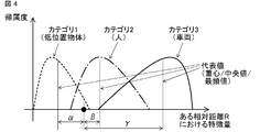
- FIG. 3 shows a schematic diagram of the degree of attribution when a category is category 1 (low position object), category 2 (person), and category 3 (vehicle) at a certain relative distance R of a certain secondary feature amount.
- FIG. 4 is a schematic diagram in the case where expressions having different degrees of belonging in the same situation are used.
- FIG. 3 shows the degree of attribution (vertical axis) over the entire feature amount (horizontal axis) in a distributed manner, and
- FIG. 4 shows representative values (for example, centroid value, median value, maximum value) in the range of each category. (Frequency).
- the method of creating the attribution database 15 is not limited to the above, and for example, the entire value range of each category may be represented in a rectangular shape. In addition, for the overlapping portion of each category, the value divided by the overlap number can be used as the attribution distribution of each category.
- the database area (memory) can be reduced.
- the attribution database 15 can be created by acquiring several samples (teacher data) of each category. For example, in order to obtain the attribution distribution shown in FIG. 3, after creating a histogram of a sample (teacher data), the maximum value can be normalized. In the example of FIG. 3, the attribution distribution is created for each relative distance R. However, by setting the relative distance finely (for example, 1 m), the characteristics for each distance can be finely reflected. It becomes possible. In addition, the area (memory) of the database can be reduced by collectively setting the relative distance to areas having similar characteristics of the secondary feature amount, for example, as far / near. The attribution distribution can also be created for each relative speed.
- the characteristic amount that captures changes at multiple observation points such as the amount of change in the received intensity value
- an attribution distribution should be created for each speed. Therefore, it is possible to cope with this, and the effect of reducing the deterioration of the object identification performance can be expected.
- the value of each category distribution ( ⁇ , ⁇ , ⁇ ) can be performed.
- the degree of attribution can be assigned by the distance between the secondary feature value and the representative value of the degree of attribution (or the reciprocal thereof).
- FIG. 5 shows a conceptual diagram of the object determination process.
- a coefficient wi is a weighting coefficient of each secondary feature amount determined in advance.
- the relative speed is added to the secondary feature amount.
- the determination result of the previous observation time or the determination result so far can be input as the secondary feature amount.
- the weight coefficient in the object determination process can be set according to the degree of influence on the determination of each secondary feature amount. For example, when the influence levels of all the secondary feature amounts are equal, the weight coefficients are all set to the same value (for example, 1). In addition, when the degree of influence of each secondary feature varies depending on the relative distance, it is possible to identify the object with higher accuracy by changing the weighting factor for each relative distance.
- the total value of each category can be considered as a ratio or reliability that belongs to each category of the object.
- interpretation of the determination result is facilitated by expressing the value normalized by the maximum value of the total sum or as a percentage.
- the predetermined total threshold value When the total value is less than the predetermined total threshold value, it is possible to output as an uncertain category that does not belong to the predetermined category. Further, when the difference between the highest total value and the next highest total value is less than a predetermined threshold value, it is possible to output that the determination is impossible because the category cannot be narrowed down to one.
- the indeterminate category is added as a new category in the subsequent processing, so that the database can be expanded and can be appropriately determined from the next time.
- all the secondary feature values are handled equally. For example, after determining the feature value having a high influence on a certain category in the first stage and narrowing down the category, the remaining categories It is also possible to make a determination. By performing such processing, the final determination accuracy can be improved.
- the radar signal processing apparatus extracts a feature quantity effective in distinguishing a vehicle, a person, or a low-position object, such as a change amount of a received intensity value, from the information of the radar alone (a remarkable difference). Since the category is determined, it is possible to identify the object with high accuracy without complicating the system configuration.
- the category is determined for each distance using the feature amount whose characteristic changes for each distance, it is possible to perform highly accurate object identification. That is, since the category (type) of the object is determined based on the measurement result for each distance of the object acquired by the radar, it is possible to identify the object with high accuracy regardless of the distance.
- the degree of attribution is calculated for each distance between the vehicle and the object.
- the category is determined based on the observation values of two or more observation periods, so that the determination immediacy can be improved.
- change_quantity of a received intensity value determination is possible in one observation period.
- the radar signal processing apparatus extracts and determines a plurality of feature amounts, the determination can be made even when the feature amounts cannot be obtained due to partial loss or the like.
- Embodiment 2 As a second embodiment in which the present invention is different, it is conceivable to create an attribution distribution for each radar mounting position of the host vehicle. As described above, the characteristics of the radar reflected wave differ depending on the altitude of the object and the mounting position (altitude) of the own vehicle radar, such as the presence or absence of multipath generation. Therefore, when the mounting position of the own vehicle radar changes depending on the vehicle type and other conditions, it is possible to make a determination with higher accuracy by using an attribution distribution (database) specialized for the mounting position.
- database attribution distribution
- the attribution distribution is created / changed for each position where the radar of the own vehicle is attached, so that more accurate object identification is performed. It is possible.
- the embodiments can be freely combined within the scope of the invention, and the embodiments can be appropriately changed or omitted.
Landscapes
- Engineering & Computer Science (AREA)
- Radar, Positioning & Navigation (AREA)
- Remote Sensing (AREA)
- Physics & Mathematics (AREA)
- Computer Networks & Wireless Communication (AREA)
- General Physics & Mathematics (AREA)
- Electromagnetism (AREA)
- Radar Systems Or Details Thereof (AREA)
Abstract
La présente invention a pour objectif de mettre en œuvre une identification d'objet hautement précise. Une unité de traitement de stockage de données 12 identifie de manière séquentielle des valeurs de caractéristiques primaires qui sont extraites par une unité d'extraction de valeurs de caractéristiques primaires 11 et qui se rapportent à la distance et à la vitesse par rapport à un objet, un support d'objet, et une intensité de réflexion. Des valeurs de caractéristiques secondaires sont extraites par une deuxième unité d'extraction de valeurs de caractéristiques 13. La catégorie de l'objet est déterminée par une unité de détermination d'objet 16 en fonction de degrés d'appartenance dans des catégories prescrites calculées par une unité de calcul de degré d'appartenance 14 pour les distributions des valeurs de caractéristiques secondaires.
Priority Applications (5)
| Application Number | Priority Date | Filing Date | Title |
|---|---|---|---|
| US15/569,444 US10663580B2 (en) | 2015-05-29 | 2015-05-29 | Radar signal processing device |
| CN201580080067.3A CN107615090B (zh) | 2015-05-29 | 2015-05-29 | 雷达信号处理装置 |
| JP2015555467A JP5908193B1 (ja) | 2015-05-29 | 2015-05-29 | レーダ信号処理装置 |
| PCT/JP2015/065529 WO2016194036A1 (fr) | 2015-05-29 | 2015-05-29 | Dispositif de traitement de signal radar |
| EP15894071.8A EP3306340B1 (fr) | 2015-05-29 | 2015-05-29 | Dispositif de traitement de signal radar |
Applications Claiming Priority (1)
| Application Number | Priority Date | Filing Date | Title |
|---|---|---|---|
| PCT/JP2015/065529 WO2016194036A1 (fr) | 2015-05-29 | 2015-05-29 | Dispositif de traitement de signal radar |
Publications (1)
| Publication Number | Publication Date |
|---|---|
| WO2016194036A1 true WO2016194036A1 (fr) | 2016-12-08 |
Family
ID=55793188
Family Applications (1)
| Application Number | Title | Priority Date | Filing Date |
|---|---|---|---|
| PCT/JP2015/065529 WO2016194036A1 (fr) | 2015-05-29 | 2015-05-29 | Dispositif de traitement de signal radar |
Country Status (5)
| Country | Link |
|---|---|
| US (1) | US10663580B2 (fr) |
| EP (1) | EP3306340B1 (fr) |
| JP (1) | JP5908193B1 (fr) |
| CN (1) | CN107615090B (fr) |
| WO (1) | WO2016194036A1 (fr) |
Cited By (2)
| Publication number | Priority date | Publication date | Assignee | Title |
|---|---|---|---|---|
| JP2018173285A (ja) * | 2017-03-31 | 2018-11-08 | 学校法人慶應義塾 | 行動認識システム、及び行動認識方法 |
| JP2018197710A (ja) * | 2017-05-24 | 2018-12-13 | 三菱電機株式会社 | レーダ信号処理装置 |
Families Citing this family (12)
| Publication number | Priority date | Publication date | Assignee | Title |
|---|---|---|---|---|
| JP6223504B1 (ja) * | 2016-05-18 | 2017-11-01 | 三菱電機株式会社 | レーダ装置およびこれを用いたセンサフュージョン装置 |
| JP6319361B2 (ja) * | 2016-05-26 | 2018-05-09 | マツダ株式会社 | 車両用歩行者検出装置 |
| JP2018059884A (ja) * | 2016-10-07 | 2018-04-12 | 日本無線株式会社 | 物標識別装置、プログラム及び方法 |
| US11200882B2 (en) * | 2017-07-03 | 2021-12-14 | Nec Corporation | Signal processing device, signal processing method, and storage medium for storing program |
| JP6570675B2 (ja) * | 2018-02-15 | 2019-09-04 | 三菱電機株式会社 | レーダ信号処理装置 |
| CN110361710A (zh) * | 2018-04-09 | 2019-10-22 | 北京京东尚科信息技术有限公司 | 基于激光点云的物体识别方法和装置 |
| JP2020016572A (ja) * | 2018-07-26 | 2020-01-30 | 日立オートモティブシステムズ株式会社 | レーダセンサ |
| CN109407703A (zh) * | 2018-12-13 | 2019-03-01 | 广州极飞科技有限公司 | 无人机及其控制方法和装置 |
| CN112119329A (zh) * | 2019-06-28 | 2020-12-22 | 深圳市大疆创新科技有限公司 | 一种物体识别方法、毫米波雷达及车辆 |
| JP7367585B2 (ja) | 2020-03-30 | 2023-10-24 | 株式会社アイシン | 物体検出システム |
| CN111429791B (zh) * | 2020-04-09 | 2022-11-18 | 浙江大华技术股份有限公司 | 身份确定方法、装置、存储介质及电子装置 |
| KR20220010900A (ko) * | 2020-07-20 | 2022-01-27 | 현대모비스 주식회사 | 차량용 레이더 장치 및 제어방법 |
Citations (6)
| Publication number | Priority date | Publication date | Assignee | Title |
|---|---|---|---|---|
| JPH10206531A (ja) * | 1997-01-17 | 1998-08-07 | Fujitsu Ten Ltd | 車両のレーダ装置 |
| JP2004191131A (ja) * | 2002-12-10 | 2004-07-08 | Denso Corp | 物標識別方法及び装置、プログラム |
| JP2004361154A (ja) * | 2003-06-03 | 2004-12-24 | Fujitsu Ten Ltd | 目標物判別装置 |
| WO2006025453A1 (fr) * | 2004-09-01 | 2006-03-09 | Matsushita Electric Industrial Co., Ltd. | Appareil radar |
| JP2009031053A (ja) * | 2007-07-25 | 2009-02-12 | Fujitsu Ten Ltd | 前方障害物検出装置 |
| JP2013238452A (ja) * | 2012-05-14 | 2013-11-28 | Honda Elesys Co Ltd | 位置情報検出装置、位置情報検出方法、位置情報検出プログラム、及び動作制御システム |
Family Cites Families (26)
| Publication number | Priority date | Publication date | Assignee | Title |
|---|---|---|---|---|
| JP3401913B2 (ja) * | 1994-05-26 | 2003-04-28 | 株式会社デンソー | 車両用障害物認識装置 |
| JP2826494B2 (ja) * | 1995-11-21 | 1998-11-18 | 防衛庁技術研究本部長 | 目標信号検出方法及び装置 |
| SE511061C2 (sv) * | 1997-11-21 | 1999-07-26 | Celsiustech Electronics Ab | Förfarande för klassificering av upphöjda objekt |
| JP3512066B2 (ja) * | 1998-12-10 | 2004-03-29 | トヨタ自動車株式会社 | 車載用レーダ装置 |
| JP4115638B2 (ja) * | 1999-10-19 | 2008-07-09 | 本田技研工業株式会社 | 物体認識装置 |
| GB0017989D0 (en) * | 2000-07-24 | 2001-08-08 | Secr Defence | Target recognition system |
| JP3871875B2 (ja) * | 2000-11-06 | 2007-01-24 | 日本電気株式会社 | 目標類別方法及び装置 |
| DE102004047087A1 (de) * | 2004-09-29 | 2006-03-30 | Robert Bosch Gmbh | Verfahren zur Objektverifaktion in Radarsystemen für Kraftfahrzeuge |
| DE102005024716B4 (de) * | 2005-05-30 | 2023-09-21 | Robert Bosch Gmbh | Verfahren und Vorrichtung zur Erkennung und Klassifizierung von Objekten |
| US20070253625A1 (en) * | 2006-04-28 | 2007-11-01 | Bbnt Solutions Llc | Method for building robust algorithms that classify objects using high-resolution radar signals |
| JP4211809B2 (ja) * | 2006-06-30 | 2009-01-21 | トヨタ自動車株式会社 | 物体検出装置 |
| US7623061B2 (en) | 2006-11-15 | 2009-11-24 | Autoliv Asp | Method and apparatus for discriminating with respect to low elevation target objects |
| CN101178773B (zh) | 2007-12-13 | 2010-08-11 | 北京中星微电子有限公司 | 基于特征提取和分类器的图像识别系统及方法 |
| JP4905512B2 (ja) | 2009-07-09 | 2012-03-28 | 株式会社デンソー | 物標情報推定装置 |
| WO2011158292A1 (fr) * | 2010-06-16 | 2011-12-22 | トヨタ自動車株式会社 | Dispositif et procédé d'identification d'objets |
| JP2013002927A (ja) * | 2011-06-15 | 2013-01-07 | Honda Elesys Co Ltd | 障害物検知装置及びコンピュータプログラム |
| JP5852456B2 (ja) * | 2012-01-30 | 2016-02-03 | トヨタ自動車株式会社 | 周辺物体検知装置 |
| JP5926069B2 (ja) * | 2012-02-20 | 2016-05-25 | トヨタ自動車株式会社 | 障害物判定装置 |
| DE102012107445B8 (de) * | 2012-08-14 | 2016-04-28 | Jenoptik Robot Gmbh | Verfahren zur Klassifizierung von fahrenden Fahrzeugen |
| DE102012107444B3 (de) * | 2012-08-14 | 2013-03-07 | Jenoptik Robot Gmbh | Verfahren zur Klassifizierung von fahrenden Fahrzeugen durch Verfolgung einer Positionsgröße des Fahrzeuges |
| JP6212860B2 (ja) * | 2012-12-27 | 2017-10-18 | 株式会社デンソー | 車載レーダ装置 |
| JP6205729B2 (ja) * | 2013-01-21 | 2017-10-04 | 株式会社デンソー | レーダ装置 |
| JP6369035B2 (ja) * | 2013-02-05 | 2018-08-08 | 株式会社デンソー | 物標検出装置 |
| JP6170704B2 (ja) * | 2013-03-29 | 2017-07-26 | 富士通テン株式会社 | レーダ装置、および、信号処理方法 |
| US20150378014A1 (en) * | 2013-08-07 | 2015-12-31 | Sandia Corporation | Ascertaining class of a vehicle captured in an image |
| US9664779B2 (en) * | 2014-07-03 | 2017-05-30 | GM Global Technology Operations LLC | Object classification for vehicle radar systems |
-
2015
- 2015-05-29 WO PCT/JP2015/065529 patent/WO2016194036A1/fr active Application Filing
- 2015-05-29 US US15/569,444 patent/US10663580B2/en active Active
- 2015-05-29 EP EP15894071.8A patent/EP3306340B1/fr active Active
- 2015-05-29 CN CN201580080067.3A patent/CN107615090B/zh active Active
- 2015-05-29 JP JP2015555467A patent/JP5908193B1/ja active Active
Patent Citations (6)
| Publication number | Priority date | Publication date | Assignee | Title |
|---|---|---|---|---|
| JPH10206531A (ja) * | 1997-01-17 | 1998-08-07 | Fujitsu Ten Ltd | 車両のレーダ装置 |
| JP2004191131A (ja) * | 2002-12-10 | 2004-07-08 | Denso Corp | 物標識別方法及び装置、プログラム |
| JP2004361154A (ja) * | 2003-06-03 | 2004-12-24 | Fujitsu Ten Ltd | 目標物判別装置 |
| WO2006025453A1 (fr) * | 2004-09-01 | 2006-03-09 | Matsushita Electric Industrial Co., Ltd. | Appareil radar |
| JP2009031053A (ja) * | 2007-07-25 | 2009-02-12 | Fujitsu Ten Ltd | 前方障害物検出装置 |
| JP2013238452A (ja) * | 2012-05-14 | 2013-11-28 | Honda Elesys Co Ltd | 位置情報検出装置、位置情報検出方法、位置情報検出プログラム、及び動作制御システム |
Non-Patent Citations (1)
| Title |
|---|
| See also references of EP3306340A4 * |
Cited By (4)
| Publication number | Priority date | Publication date | Assignee | Title |
|---|---|---|---|---|
| JP2018173285A (ja) * | 2017-03-31 | 2018-11-08 | 学校法人慶應義塾 | 行動認識システム、及び行動認識方法 |
| JP7150292B2 (ja) | 2017-03-31 | 2022-10-11 | 慶應義塾 | 行動認識システム、及び行動認識方法 |
| JP2018197710A (ja) * | 2017-05-24 | 2018-12-13 | 三菱電機株式会社 | レーダ信号処理装置 |
| US10663561B2 (en) | 2017-05-24 | 2020-05-26 | Mitsubishi Electric Corporation | Radar signal processing device |
Also Published As
| Publication number | Publication date |
|---|---|
| EP3306340A4 (fr) | 2019-01-23 |
| EP3306340A1 (fr) | 2018-04-11 |
| JP5908193B1 (ja) | 2016-04-26 |
| US10663580B2 (en) | 2020-05-26 |
| CN107615090B (zh) | 2021-06-11 |
| CN107615090A (zh) | 2018-01-19 |
| US20180081052A1 (en) | 2018-03-22 |
| JPWO2016194036A1 (ja) | 2017-06-22 |
| EP3306340B1 (fr) | 2021-06-23 |
Similar Documents
| Publication | Publication Date | Title |
|---|---|---|
| JP5908193B1 (ja) | レーダ信号処理装置 | |
| EP3663790A1 (fr) | Procédé et appareil de traitement de données radar | |
| KR102099851B1 (ko) | 자동차 레이더 시스템에서 탐지된 타겟들의 클러스터링 방법 및 이를 위한 장치 | |
| JP6223504B1 (ja) | レーダ装置およびこれを用いたセンサフュージョン装置 | |
| CN110361736A (zh) | 识别物体的方法 | |
| JP6699904B2 (ja) | レーダ装置及びそのレーダ信号処理方法 | |
| KR101628154B1 (ko) | 수신 신호 세기를 이용한 다중 표적 추적 방법 | |
| CN109154655A (zh) | 目标信号检测方法、设备、无人机及农业无人机 | |
| CN113536850B (zh) | 基于77g毫米波雷达的目标物体大小测试方法和装置 | |
| JP6570675B2 (ja) | レーダ信号処理装置 | |
| US20220003860A1 (en) | Determining the orientation of objects using radar or through the use of electromagnetic interrogation radiation | |
| CN112241003A (zh) | 用于对象检测的方法和系统 | |
| CN112034464A (zh) | 一种目标分类方法 | |
| EP3683596A1 (fr) | Procédé et processeur pour déterminer des informations spatiales relatives à un véhicule | |
| CN116964472A (zh) | 用于借助于雷达传感器系统的反射信号来探测环境的至少一个对象的方法 | |
| Park et al. | Ground reflection-based misalignment detection of automotive radar sensors | |
| RU157396U1 (ru) | Устройство распознавания винтовых летательных аппаратов | |
| US11668799B2 (en) | Histogram based L-shape detection of target objects | |
| EP3851870A1 (fr) | Procédé permettant de déterminer des données de position et/ou des données de mouvement d'un véhicule | |
| CN109283507B (zh) | 一种基于时频域特征的雷达目标识别方法及系统 | |
| Park et al. | Bi-directional LSTM-based Overhead Target Classification for Automotive Radar Systems | |
| JP2005114416A (ja) | 擾乱検出装置 | |
| KR102529397B1 (ko) | 레이더 신호 정보를 이용한 표적 식별 알고리즘. | |
| CN111337920A (zh) | 一种防止云雾干扰的弹载雷达对地探测方法及装置 | |
| US10591583B2 (en) | Method for processing a radar signal in land/sea detection mode; processing system and associated computer program product |
Legal Events
| Date | Code | Title | Description |
|---|---|---|---|
| ENP | Entry into the national phase |
Ref document number: 2015555467 Country of ref document: JP Kind code of ref document: A |
|
| 121 | Ep: the epo has been informed by wipo that ep was designated in this application |
Ref document number: 15894071 Country of ref document: EP Kind code of ref document: A1 |
|
| WWE | Wipo information: entry into national phase |
Ref document number: 15569444 Country of ref document: US |
|
| NENP | Non-entry into the national phase |
Ref country code: DE |