WO2016190413A1 - 液体吐出ヘッド、および記録装置 - Google Patents
液体吐出ヘッド、および記録装置 Download PDFInfo
- Publication number
- WO2016190413A1 WO2016190413A1 PCT/JP2016/065706 JP2016065706W WO2016190413A1 WO 2016190413 A1 WO2016190413 A1 WO 2016190413A1 JP 2016065706 W JP2016065706 W JP 2016065706W WO 2016190413 A1 WO2016190413 A1 WO 2016190413A1
- Authority
- WO
- WIPO (PCT)
- Prior art keywords
- flow path
- path member
- opening
- liquid
- liquid discharge
- Prior art date
- Legal status (The legal status is an assumption and is not a legal conclusion. Google has not performed a legal analysis and makes no representation as to the accuracy of the status listed.)
- Ceased
Links
Images


Classifications
-
- B—PERFORMING OPERATIONS; TRANSPORTING
- B41—PRINTING; LINING MACHINES; TYPEWRITERS; STAMPS
- B41J—TYPEWRITERS; SELECTIVE PRINTING MECHANISMS, i.e. MECHANISMS PRINTING OTHERWISE THAN FROM A FORME; CORRECTION OF TYPOGRAPHICAL ERRORS
- B41J2/00—Typewriters or selective printing mechanisms characterised by the printing or marking process for which they are designed
- B41J2/005—Typewriters or selective printing mechanisms characterised by the printing or marking process for which they are designed characterised by bringing liquid or particles selectively into contact with a printing material
- B41J2/01—Ink jet
- B41J2/135—Nozzles
- B41J2/14—Structure thereof only for on-demand ink jet heads
- B41J2/14201—Structure of print heads with piezoelectric elements
-
- B—PERFORMING OPERATIONS; TRANSPORTING
- B41—PRINTING; LINING MACHINES; TYPEWRITERS; STAMPS
- B41J—TYPEWRITERS; SELECTIVE PRINTING MECHANISMS, i.e. MECHANISMS PRINTING OTHERWISE THAN FROM A FORME; CORRECTION OF TYPOGRAPHICAL ERRORS
- B41J2/00—Typewriters or selective printing mechanisms characterised by the printing or marking process for which they are designed
- B41J2/005—Typewriters or selective printing mechanisms characterised by the printing or marking process for which they are designed characterised by bringing liquid or particles selectively into contact with a printing material
- B41J2/01—Ink jet
- B41J2/135—Nozzles
- B41J2/14—Structure thereof only for on-demand ink jet heads
- B41J2/14201—Structure of print heads with piezoelectric elements
- B41J2/14209—Structure of print heads with piezoelectric elements of finger type, chamber walls consisting integrally of piezoelectric material
-
- B—PERFORMING OPERATIONS; TRANSPORTING
- B41—PRINTING; LINING MACHINES; TYPEWRITERS; STAMPS
- B41J—TYPEWRITERS; SELECTIVE PRINTING MECHANISMS, i.e. MECHANISMS PRINTING OTHERWISE THAN FROM A FORME; CORRECTION OF TYPOGRAPHICAL ERRORS
- B41J2/00—Typewriters or selective printing mechanisms characterised by the printing or marking process for which they are designed
- B41J2/005—Typewriters or selective printing mechanisms characterised by the printing or marking process for which they are designed characterised by bringing liquid or particles selectively into contact with a printing material
- B41J2/01—Ink jet
- B41J2/015—Ink jet characterised by the jet generation process
- B41J2/04—Ink jet characterised by the jet generation process generating single droplets or particles on demand
- B41J2/045—Ink jet characterised by the jet generation process generating single droplets or particles on demand by pressure, e.g. electromechanical transducers
- B41J2/04501—Control methods or devices therefor, e.g. driver circuits, control circuits
-
- B—PERFORMING OPERATIONS; TRANSPORTING
- B41—PRINTING; LINING MACHINES; TYPEWRITERS; STAMPS
- B41J—TYPEWRITERS; SELECTIVE PRINTING MECHANISMS, i.e. MECHANISMS PRINTING OTHERWISE THAN FROM A FORME; CORRECTION OF TYPOGRAPHICAL ERRORS
- B41J2/00—Typewriters or selective printing mechanisms characterised by the printing or marking process for which they are designed
- B41J2/005—Typewriters or selective printing mechanisms characterised by the printing or marking process for which they are designed characterised by bringing liquid or particles selectively into contact with a printing material
- B41J2/01—Ink jet
- B41J2/135—Nozzles
- B41J2/14—Structure thereof only for on-demand ink jet heads
- B41J2/14016—Structure of bubble jet print heads
- B41J2/14024—Assembling head parts
-
- B—PERFORMING OPERATIONS; TRANSPORTING
- B41—PRINTING; LINING MACHINES; TYPEWRITERS; STAMPS
- B41J—TYPEWRITERS; SELECTIVE PRINTING MECHANISMS, i.e. MECHANISMS PRINTING OTHERWISE THAN FROM A FORME; CORRECTION OF TYPOGRAPHICAL ERRORS
- B41J2/00—Typewriters or selective printing mechanisms characterised by the printing or marking process for which they are designed
- B41J2/005—Typewriters or selective printing mechanisms characterised by the printing or marking process for which they are designed characterised by bringing liquid or particles selectively into contact with a printing material
- B41J2/01—Ink jet
- B41J2/135—Nozzles
- B41J2/14—Structure thereof only for on-demand ink jet heads
- B41J2/14201—Structure of print heads with piezoelectric elements
- B41J2/14233—Structure of print heads with piezoelectric elements of film type, deformed by bending and disposed on a diaphragm
-
- B—PERFORMING OPERATIONS; TRANSPORTING
- B41—PRINTING; LINING MACHINES; TYPEWRITERS; STAMPS
- B41J—TYPEWRITERS; SELECTIVE PRINTING MECHANISMS, i.e. MECHANISMS PRINTING OTHERWISE THAN FROM A FORME; CORRECTION OF TYPOGRAPHICAL ERRORS
- B41J2/00—Typewriters or selective printing mechanisms characterised by the printing or marking process for which they are designed
- B41J2/005—Typewriters or selective printing mechanisms characterised by the printing or marking process for which they are designed characterised by bringing liquid or particles selectively into contact with a printing material
- B41J2/01—Ink jet
- B41J2/17—Ink jet characterised by ink handling
- B41J2/175—Ink supply systems ; Circuit parts therefor
- B41J2/17566—Ink level or ink residue control
-
- B—PERFORMING OPERATIONS; TRANSPORTING
- B41—PRINTING; LINING MACHINES; TYPEWRITERS; STAMPS
- B41J—TYPEWRITERS; SELECTIVE PRINTING MECHANISMS, i.e. MECHANISMS PRINTING OTHERWISE THAN FROM A FORME; CORRECTION OF TYPOGRAPHICAL ERRORS
- B41J2/00—Typewriters or selective printing mechanisms characterised by the printing or marking process for which they are designed
- B41J2/005—Typewriters or selective printing mechanisms characterised by the printing or marking process for which they are designed characterised by bringing liquid or particles selectively into contact with a printing material
- B41J2/01—Ink jet
- B41J2/17—Ink jet characterised by ink handling
- B41J2/195—Ink jet characterised by ink handling for monitoring ink quality
-
- B—PERFORMING OPERATIONS; TRANSPORTING
- B41—PRINTING; LINING MACHINES; TYPEWRITERS; STAMPS
- B41J—TYPEWRITERS; SELECTIVE PRINTING MECHANISMS, i.e. MECHANISMS PRINTING OTHERWISE THAN FROM A FORME; CORRECTION OF TYPOGRAPHICAL ERRORS
- B41J2/00—Typewriters or selective printing mechanisms characterised by the printing or marking process for which they are designed
- B41J2/005—Typewriters or selective printing mechanisms characterised by the printing or marking process for which they are designed characterised by bringing liquid or particles selectively into contact with a printing material
- B41J2/01—Ink jet
- B41J2/21—Ink jet for multi-colour printing
-
- B—PERFORMING OPERATIONS; TRANSPORTING
- B41—PRINTING; LINING MACHINES; TYPEWRITERS; STAMPS
- B41J—TYPEWRITERS; SELECTIVE PRINTING MECHANISMS, i.e. MECHANISMS PRINTING OTHERWISE THAN FROM A FORME; CORRECTION OF TYPOGRAPHICAL ERRORS
- B41J2/00—Typewriters or selective printing mechanisms characterised by the printing or marking process for which they are designed
- B41J2/22—Typewriters or selective printing mechanisms characterised by the printing or marking process for which they are designed characterised by selective application of impact or pressure on a printing material or impression-transfer material
- B41J2/23—Typewriters or selective printing mechanisms characterised by the printing or marking process for which they are designed characterised by selective application of impact or pressure on a printing material or impression-transfer material using print wires
- B41J2/305—Ink supply apparatus
-
- B—PERFORMING OPERATIONS; TRANSPORTING
- B41—PRINTING; LINING MACHINES; TYPEWRITERS; STAMPS
- B41J—TYPEWRITERS; SELECTIVE PRINTING MECHANISMS, i.e. MECHANISMS PRINTING OTHERWISE THAN FROM A FORME; CORRECTION OF TYPOGRAPHICAL ERRORS
- B41J2/00—Typewriters or selective printing mechanisms characterised by the printing or marking process for which they are designed
- B41J2/005—Typewriters or selective printing mechanisms characterised by the printing or marking process for which they are designed characterised by bringing liquid or particles selectively into contact with a printing material
- B41J2/01—Ink jet
- B41J2/135—Nozzles
- B41J2/14—Structure thereof only for on-demand ink jet heads
- B41J2/14201—Structure of print heads with piezoelectric elements
- B41J2/14209—Structure of print heads with piezoelectric elements of finger type, chamber walls consisting integrally of piezoelectric material
- B41J2002/14225—Finger type piezoelectric element on only one side of the chamber
-
- B—PERFORMING OPERATIONS; TRANSPORTING
- B41—PRINTING; LINING MACHINES; TYPEWRITERS; STAMPS
- B41J—TYPEWRITERS; SELECTIVE PRINTING MECHANISMS, i.e. MECHANISMS PRINTING OTHERWISE THAN FROM A FORME; CORRECTION OF TYPOGRAPHICAL ERRORS
- B41J2/00—Typewriters or selective printing mechanisms characterised by the printing or marking process for which they are designed
- B41J2/005—Typewriters or selective printing mechanisms characterised by the printing or marking process for which they are designed characterised by bringing liquid or particles selectively into contact with a printing material
- B41J2/01—Ink jet
- B41J2/135—Nozzles
- B41J2/14—Structure thereof only for on-demand ink jet heads
- B41J2002/14322—Print head without nozzle
-
- B—PERFORMING OPERATIONS; TRANSPORTING
- B41—PRINTING; LINING MACHINES; TYPEWRITERS; STAMPS
- B41J—TYPEWRITERS; SELECTIVE PRINTING MECHANISMS, i.e. MECHANISMS PRINTING OTHERWISE THAN FROM A FORME; CORRECTION OF TYPOGRAPHICAL ERRORS
- B41J2/00—Typewriters or selective printing mechanisms characterised by the printing or marking process for which they are designed
- B41J2/005—Typewriters or selective printing mechanisms characterised by the printing or marking process for which they are designed characterised by bringing liquid or particles selectively into contact with a printing material
- B41J2/01—Ink jet
- B41J2/135—Nozzles
- B41J2/14—Structure thereof only for on-demand ink jet heads
- B41J2002/14362—Assembling elements of heads
-
- B—PERFORMING OPERATIONS; TRANSPORTING
- B41—PRINTING; LINING MACHINES; TYPEWRITERS; STAMPS
- B41J—TYPEWRITERS; SELECTIVE PRINTING MECHANISMS, i.e. MECHANISMS PRINTING OTHERWISE THAN FROM A FORME; CORRECTION OF TYPOGRAPHICAL ERRORS
- B41J2/00—Typewriters or selective printing mechanisms characterised by the printing or marking process for which they are designed
- B41J2/005—Typewriters or selective printing mechanisms characterised by the printing or marking process for which they are designed characterised by bringing liquid or particles selectively into contact with a printing material
- B41J2/01—Ink jet
- B41J2/135—Nozzles
- B41J2/14—Structure thereof only for on-demand ink jet heads
- B41J2002/14419—Manifold
-
- B—PERFORMING OPERATIONS; TRANSPORTING
- B41—PRINTING; LINING MACHINES; TYPEWRITERS; STAMPS
- B41J—TYPEWRITERS; SELECTIVE PRINTING MECHANISMS, i.e. MECHANISMS PRINTING OTHERWISE THAN FROM A FORME; CORRECTION OF TYPOGRAPHICAL ERRORS
- B41J2/00—Typewriters or selective printing mechanisms characterised by the printing or marking process for which they are designed
- B41J2/005—Typewriters or selective printing mechanisms characterised by the printing or marking process for which they are designed characterised by bringing liquid or particles selectively into contact with a printing material
- B41J2/01—Ink jet
- B41J2/135—Nozzles
- B41J2/14—Structure thereof only for on-demand ink jet heads
- B41J2002/14459—Matrix arrangement of the pressure chambers
-
- B—PERFORMING OPERATIONS; TRANSPORTING
- B41—PRINTING; LINING MACHINES; TYPEWRITERS; STAMPS
- B41J—TYPEWRITERS; SELECTIVE PRINTING MECHANISMS, i.e. MECHANISMS PRINTING OTHERWISE THAN FROM A FORME; CORRECTION OF TYPOGRAPHICAL ERRORS
- B41J2/00—Typewriters or selective printing mechanisms characterised by the printing or marking process for which they are designed
- B41J2/005—Typewriters or selective printing mechanisms characterised by the printing or marking process for which they are designed characterised by bringing liquid or particles selectively into contact with a printing material
- B41J2/01—Ink jet
- B41J2/135—Nozzles
- B41J2/14—Structure thereof only for on-demand ink jet heads
- B41J2002/14491—Electrical connection
-
- B—PERFORMING OPERATIONS; TRANSPORTING
- B41—PRINTING; LINING MACHINES; TYPEWRITERS; STAMPS
- B41J—TYPEWRITERS; SELECTIVE PRINTING MECHANISMS, i.e. MECHANISMS PRINTING OTHERWISE THAN FROM A FORME; CORRECTION OF TYPOGRAPHICAL ERRORS
- B41J2202/00—Embodiments of or processes related to ink-jet or thermal heads
- B41J2202/01—Embodiments of or processes related to ink-jet heads
- B41J2202/12—Embodiments of or processes related to ink-jet heads with ink circulating through the whole print head
-
- B—PERFORMING OPERATIONS; TRANSPORTING
- B41—PRINTING; LINING MACHINES; TYPEWRITERS; STAMPS
- B41J—TYPEWRITERS; SELECTIVE PRINTING MECHANISMS, i.e. MECHANISMS PRINTING OTHERWISE THAN FROM A FORME; CORRECTION OF TYPOGRAPHICAL ERRORS
- B41J2202/00—Embodiments of or processes related to ink-jet or thermal heads
- B41J2202/01—Embodiments of or processes related to ink-jet heads
- B41J2202/20—Modules
-
- B—PERFORMING OPERATIONS; TRANSPORTING
- B41—PRINTING; LINING MACHINES; TYPEWRITERS; STAMPS
- B41J—TYPEWRITERS; SELECTIVE PRINTING MECHANISMS, i.e. MECHANISMS PRINTING OTHERWISE THAN FROM A FORME; CORRECTION OF TYPOGRAPHICAL ERRORS
- B41J2202/00—Embodiments of or processes related to ink-jet or thermal heads
- B41J2202/01—Embodiments of or processes related to ink-jet heads
- B41J2202/21—Line printing
Definitions
- the present invention relates to a liquid discharge head and a recording apparatus.
- liquid ejection heads that perform various types of printing by ejecting liquid onto a recording medium are known as printing heads.
- a liquid discharge head the first surface, a plurality of discharge holes provided in the first surface, a plurality of pressurizing chambers respectively communicating with the plurality of discharge holes, and the opposite side of the first surface are located.
- a first flow path member having a second surface, a pressure member provided on the second surface, a third surface, a fourth surface located on the opposite side of the third surface, and a fourth surface What is provided with the protruding part which protrudes, and the 2nd flow-path member which has the 1st through-hole provided in the protruding part is known. Thereby, the liquid supplied to the second flow path member is prevented from flowing into the inside through the first through hole (see, for example, Patent Document 1).
- the liquid discharge head includes a first surface, a plurality of discharge holes provided in the first surface, a plurality of pressurizing chambers respectively communicating with the plurality of discharge holes, and a side opposite to the first surface.
- a first flow path member having a second surface located on the surface, a pressure member provided on the second surface, a third surface, a fourth surface located on the opposite side of the third surface A raised portion protruding from the fourth surface, and a second flow path member having a first through hole provided in the raised portion.
- the second flow path member is provided on a region of the second surface of the first flow path member where the pressure member is not disposed.
- the outer periphery of the said protruding part is located inside the outer periphery of the said 4th surface in planar view.
- the recording apparatus of the present disclosure includes the liquid discharge head, a transport unit that transports a recording medium to the liquid discharge head, and a control unit that controls the liquid discharge head.
- FIG. 2A is a side view schematically showing a recording apparatus including a liquid ejection head according to the first embodiment
- FIG. 2B is a plan view schematically showing the recording apparatus shown in FIG.
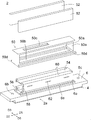
- FIG. 3 is an exploded perspective view of the liquid ejection head according to the first embodiment.
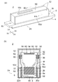
- (A) is a perspective view of the liquid discharge head of FIG. 2, and (b) is a IIIb-IIIb cross-sectional view of FIG. 3 (a).
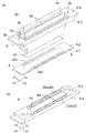
- (A) is a disassembled perspective view of a head main body
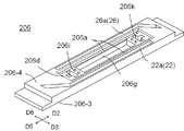
- (b) is the perspective view which looked at the 2nd flow path member from the 3rd surface side.
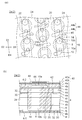
- FIG. 7A is an enlarged plan view showing a part of FIG. 6, and FIG. 7B is a cross-sectional view taken along the line VIIb-VIIb of FIG. (A) is a top view of a 2nd flow path member, (b) is sectional drawing of the liquid discharge head shown expanded.
- FIG. 2 shows a liquid discharge head according to a second embodiment, wherein (a) is a perspective view of the second flow path member as viewed from the third surface side, and (b) is a view of the liquid discharge head according to the second embodiment. It is sectional drawing which expands and shows a part.
- FIG. 10 is a perspective view illustrating a liquid discharge head according to a third embodiment, as viewed from a third surface side of a second flow path member.
- FIG. 11A is an enlarged plan view showing a part of a liquid discharge head according to a third embodiment
- FIG. 11B is a sectional view taken along line XIb-XIb in FIG.
- a color ink jet printer 1 (hereinafter referred to as a printer 1) including a liquid ejection head 2 according to the first embodiment will be described with reference to FIG.
- a first direction D1, a second direction D2, a third direction D3, a fourth direction D4, a fifth direction D5, and a sixth direction D6 are illustrated.
- the first direction D1 is one side in the direction in which the first common flow path 20 and the second common flow path 24 extend
- the fourth direction D4 is the direction in which the first common flow path 20 and the second common flow path 24 extend. On the other side.
- the second direction D2 is one side in the direction in which the first integrated flow path 22 and the second integrated flow path 26 extend
- the fifth direction D5 is the direction in which the first integrated flow path 22 and the second integrated flow path 26 extend.
- the third direction D3 is one side of the direction orthogonal to the extending direction of the first integrated flow path 22 and the second integrated flow path 26
- the sixth direction D6 is the first integrated flow path 22 and the second integrated flow path. This is the other side of the direction orthogonal to the direction in which 26 extends.
- the printer 1 moves the recording medium P relative to the liquid ejection head 2 by conveying the recording medium P from the conveying roller 74 a to the conveying roller 74 b.
- the control unit 76 controls the liquid ejection head 2 based on image and character data, ejects the liquid toward the recording medium P, causes droplets to land on the recording medium P, and prints on the recording medium P. To do.
- the liquid discharge head 2 is fixed to the printer 1, and the printer 1 is a so-called line printer.
- Another embodiment of the recording apparatus is a so-called serial printer.
- a flat head mounting frame 70 is fixed to the printer 1 so as to be substantially parallel to the recording medium P.
- the head mounting frame 70 is provided with 20 holes (not shown), and the 20 liquid discharge heads 2 are mounted in the respective holes.
- the five liquid ejection heads 2 constitute one head group 72, and the printer 1 has four head groups 72.
- the liquid discharge head 2 has a long and narrow shape extending from the second direction D2 to the fifth direction D5.
- the three liquid discharge heads 2 are arranged along the second direction D2 to the fifth direction D5, and the other two liquid discharge heads 2 are shifted in the sixth direction D5.
- Adjacent liquid ejection heads 2 are arranged such that the printable range of each liquid ejection head 2 is connected from the second direction D2 to the fifth direction D5, or the ends overlap. Printing without gaps in the width direction is possible.
- the four head groups 72 are arranged from the third direction D3 to the sixth direction D6.
- Each liquid discharge head 2 is supplied with ink from a liquid tank (not shown).
- the liquid discharge heads 2 belonging to one head group 72 are supplied with the same color ink, and the four head groups print four color inks.
- the colors of ink ejected from each head group 72 are, for example, magenta (M), yellow (Y), cyan (C), and black (K).
- the number of liquid discharge heads 2 mounted on the printer 1 may be one if it is a single color and the range that can be printed by one liquid discharge head 2 is printed.
- the number of the liquid ejection heads 2 included in the head group 72 or the number of the head groups 72 can be appropriately changed depending on the printing target and printing conditions. For example, the number of head groups 72 may be increased in order to perform multicolor printing.
- the printing speed that is, the transport speed can be increased.
- a plurality of head groups 72 for printing in the same color may be prepared and arranged shifted in the third direction D3 to increase the resolution in the width direction of the recording medium P.
- a liquid such as a coating agent may be printed for surface treatment of the recording medium P.
- the printer 1 performs printing on the recording medium P.
- the recording medium P is wound around the transport roller 74 a and passes between the two transport rollers 74 c and then passes below the liquid ejection head 2 mounted on the head mounting frame 70. Thereafter, it passes between the two transport rollers 74d and is finally collected by the transport roller 74b.
- the recording medium P may be cloth or the like in addition to printing paper.
- the printer 1 is configured to convey a conveyance belt instead of the recording medium P, and the recording medium P is a sheet of paper, cut cloth, wood placed on the conveyance belt in addition to the roll-shaped one. Or a tile or the like.
- a wiring pattern of an electronic device may be printed by discharging a liquid containing conductive particles from the liquid discharge head 2.
- the chemical may be produced by discharging a predetermined amount of liquid chemical agent or a liquid containing the chemical agent from the liquid discharge head 2 toward the reaction container or the like to cause a reaction.
- a position sensor, a speed sensor, a temperature sensor, or the like may be attached to the printer 1, and the control unit 76 may control each part of the printer 1 according to the state of each part of the printer 1 that can be understood from the information of each sensor.
- the temperature of the liquid discharge head 2 the temperature of the liquid in the liquid tank, or the liquid in the liquid tank is liquid.
- the drive signal for ejecting the liquid in the liquid ejection head 2 may be changed.
- the liquid ejection head 2 includes a head body 2 a, a housing 50, a heat sink 52, a wiring board 54, a pressing member 56, an elastic member 58, and a signal transmission member 60. And a driver IC 62.
- the liquid ejection head 2 only needs to include the head main body 2a, and the housing 50, the heat radiating plate 52, the wiring board 54, the pressing member 56, the elastic member 58, the signal transmission member 60, and the driver IC 62 are not necessarily provided. It does not have to be.
- the signal transmission member 60 is pulled out from the head main body 2 a, and the signal transmission member 60 is electrically connected to the wiring board 54.
- the signal transmission member 60 is provided with a driver IC 62 that controls the driving of the liquid ejection head 2.
- the driver IC 62 is pressed against the heat radiating plate 52 by the pressing member 56 via the elastic member 58.
- the support member that supports the wiring board 54 is not shown.
- the heat radiating plate 52 can be formed of metal or alloy, and is provided to radiate the heat of the driver IC 62 to the outside.
- the heat radiating plate 52 is joined to the housing 50 by screws or an adhesive.
- the housing 50 is placed on the head main body 2a, and the housing 50 and the heat radiating plate 52 cover each member constituting the liquid ejection head 2.
- the housing 50 includes openings 50a, 50b, and 50c and a heat insulating portion 50d.
- the openings 50a are provided so as to face the third direction D3 and the sixth direction D6, respectively, and the heat radiating plate 52 is disposed so as to close the openings 50a.
- the opening 50b opens downward, and the wiring board 54 and the pressing member 56 are disposed inside the housing 50 through the opening 50b.
- the opening 50c opens upward and accommodates a connector (not shown) provided on the wiring board 54.
- the heat insulating portion 50d is provided so as to extend from the second direction D2 to the fifth direction D5, and is disposed between the heat dissipation plate 52 and the head body 2a. Thereby, the heat radiated to the heat radiating plate 52 is not easily transferred to the head main body 2a.
- the housing 50 can be formed of a metal, an alloy, or a resin.
- the head body 2a has a long shape from the second direction D2 to the fifth direction D5, and includes a first flow path member 4, a second flow path member 6, and And a piezoelectric actuator substrate 40.
- the piezoelectric actuator substrate 40 and the second flow path member 6 are provided on the first flow path member 4.
- the piezoelectric actuator substrate 40 is placed in a broken line area E shown in FIG.
- the piezoelectric actuator substrate 40 is provided to pressurize a plurality of pressurizing chambers 10 (see FIG. 7B) provided in the first flow path member 4, and a plurality of displacement elements 48 (FIG. 7B). )).
- the piezoelectric actuator substrate 40 having the displacement element 48 that pressurizes the pressurizing chamber 10 is a pressurizing member.
- the pressurizing member will be described using the piezoelectric actuator substrate.
- the first flow path member 4 has a flow path formed therein, and guides the liquid supplied from the second flow path member 6 to the discharge hole 8 (see FIG. 7B).
- the first flow path member 4 has a first surface 4-1 and a second surface 4-2, and a discharge hole 8 is formed in the first surface 4-1.
- openings 20a and 24a are formed in the second surface 4-2.
- the openings 20a are arranged along the second direction D2 to the fifth direction D5, and are arranged at the end of the second surface 4-2 in the third direction D3.
- the openings 24a are arranged along the second direction D2 to the fifth direction D5, and are arranged at the end of the second surface 4-2 in the sixth direction D6.
- the second flow path member 6 has a flow path formed therein, and guides the liquid supplied from the liquid tank provided outside to the first flow path member 4.
- the second flow path member 6 has a third surface 6-3 and a fourth surface 6-4, and the third surface 6-3 of the second flow path member 6 is the first flow path member 4. On the second surface 4-2.
- the second flow path member 6 is joined to the first flow path member 4 via an adhesive (not shown) outside the placement area E of the piezoelectric actuator substrate 40 indicated by a broken line. Thereby, the 1st flow path member 4 and the 2nd flow path member 6 are connecting.
- the second flow path member 6 includes a plurality of first through holes 6a, through holes 6b and 6c, a first opening 6d, openings 22a and 26a, and a raised portion 6e.
- the raised portion 6e has a connecting portion 6f that connects the adjacent first through holes 6a.
- the first through hole 6 a is provided in the raised portion 6 e so as to extend from the second direction D 2 to the fifth direction D 5, and is disposed outside the mounting area E of the piezoelectric actuator substrate 40.
- the signal transmission member 60 is inserted through the first through hole 6a.
- the through-hole 6b is disposed at the end of the second flow path member 6 in the second direction D2, and supplies the liquid from the liquid tank to the second flow path member 6.
- the through hole 6c is disposed at the end of the second flow path member 6 in the fifth direction D5, and collects the liquid from the second flow path member 6 to the liquid tank.
- the first opening 6 d is provided on the third surface 6-3 of the second flow path member 6, and the piezoelectric actuator substrate 40 is accommodated in the space formed by the first opening 6 d and the first flow path member 4. ing.
- the opening 22a is provided on the third surface 6-3 of the second flow path member 6, and is provided so as to extend from the second direction D2 toward the fifth direction D5.
- the opening 22a is formed at the end of the second flow path member 6 in the third direction D3, and is provided on the third direction D3 side with respect to the first through hole 6a.
- the opening 22 a communicates with the through hole 6 b, and the opening 22 a is sealed by the first flow path member 4, thereby forming the first integrated flow path 22.
- the opening 26a is provided on the third surface 6-3 of the second flow path member 6, and is provided so as to extend from the second direction D2 toward the fifth direction D5.
- the opening 26a is formed at the end of the second flow path member 6 in the sixth direction D6, and is provided on the sixth direction D6 side with respect to the first through hole 6a.
- the opening 26 a communicates with the through hole 6 c, and the second integrated flow path 26 is formed by sealing the opening 26 a with the first flow path member 4.
- the first integrated channel 22 is formed so as to extend from the second direction D2 to the fifth direction D5, and supplies the liquid to the opening 20a of the first channel member 4.
- the second integrated channel 26 is formed to extend from the second direction D2 to the fifth direction D5, and collects the liquid from the opening 24a of the first channel member 4.
- the raised portion 6e protrudes upward from the fourth surface 6-4 and is disposed higher than the fourth surface 6-4.
- the first through hole 6a is provided in the raised portion 6e, and the height of the surface on which the first through hole 6a is formed is higher than that of the fourth surface 6-4 on which the through holes 6b and 6c are formed. Yes.
- the raised portion 6e can have a height of 1 to 5 mm, and the height of 1 mm or more makes it difficult for the liquid to flow from the first through hole 6a.
- the connecting portion 6f is provided so as to connect the adjacent first through holes 6a, and is formed to extend from the second direction D2 to the fifth direction D5.
- the connecting portion 6f the piezoelectric actuator substrate 40 is covered with the connecting portion 6f, and the liquid is less likely to adhere to the piezoelectric actuator substrate 40 located in the first opening 6d.
- the rigidity of the second flow path member 6 can be increased, and the second flow path member 6 is hardly deformed.
- the liquid supplied from the liquid tank to the through hole 6 b is supplied to the first integrated flow path 22 and the first common flow path 20 through the openings 20 a and 22 a.
- the liquid is supplied to the first flow path member 4.
- recovered by the 2nd common flow path 24 flows into the 2nd integrated flow path 26 via opening 24a, 26a, and a liquid is collect
- the first flow path member 4 will be described with reference to FIGS.
- the first flow path member 4 is formed by laminating a plurality of plates 4a to 4g, and has a first surface 4-1 and a second surface 4-2.
- a piezoelectric actuator substrate 40 is placed on the second surface 4-2, and liquid is discharged from the discharge holes 8 provided in the first surface 4-1.
- the plurality of plates 4a to 4g can be formed of metal, alloy, or resin. Note that the first flow path member 4 may be integrally formed of resin without stacking the plurality of plates 4a to 4g.
- the first flow path member 4 is formed with a plurality of first common flow paths 20, a plurality of second common flow paths 24, and a plurality of individual units 15, and an opening 20a, 24a is formed.
- the first common flow path 20 is provided so as to extend from the first direction D1 to the fourth direction D4, and is formed so as to communicate with the opening 20a.
- a plurality of first common flow paths 20 are arranged from the second direction D2 toward the fifth direction D5.
- the second common flow path 24 is provided so as to extend from the fourth direction D4 to the first direction D1, and is formed so as to communicate with the opening 24a.
- a plurality of second common flow paths 24 are arranged from the second direction D2 to the fifth direction D5, and are disposed between the adjacent first common flow paths 20. Therefore, the first common channel 20 and the second common channel 24 are alternately arranged from the second direction D2 toward the fifth direction D5.
- the discharge unit 15 is provided between the first common flow path 20 and the second common flow path 24 adjacent to each other, and is formed in a matrix in the planar direction of the first flow path member 4. An angle formed by the first direction D1 and the fourth direction D4, and the second direction D2 and the fifth direction D5 is larger than a right angle. For this reason, the discharge units 15 connected to the same first common flow path 20 are displaced in the second direction D2, and printing is performed so as to fill a predetermined range with pixels formed by the discharged liquid. it can.
- discharge holes 8 are projected in the third direction D3 and the sixth direction D6, 32 discharge holes 8 are projected in the range of the virtual straight line R, and the discharge holes 8 are arranged at intervals of 360 dpi in the virtual straight line R.
- the recording medium P is conveyed and printed in a direction orthogonal to the virtual straight line R, printing can be performed with a resolution of 360 dpi.
- the discharge unit 15 has a discharge hole 8, a pressurizing chamber 10, a first individual channel 12, and a second individual channel 14.
- the liquid discharge head 2 the liquid is supplied from the first individual channel 12 to the pressurizing chamber 10, and the second individual channel 14 collects the liquid from the pressurizing chamber 10.
- the pressurizing chamber 10 has a pressurizing chamber main body 10a and a partial flow path 10b.
- the pressurizing chamber body 10a has a circular shape in plan view, and a partial flow path 10b extends downward from the center of the pressurizing chamber body 10a.
- the pressurizing chamber body 10a is configured to apply pressure to the liquid in the partial flow path 10b by receiving pressure from a displacement element 48 provided on the pressurizing chamber body 10a.
- the pressurizing chamber body 10a has a right circular column shape, and the planar shape is circular.
- the planar shape is circular, the displacement amount and the volume change of the pressurizing chamber 10 caused by the displacement can be increased.
- the partial flow path 10b has a right circular cylinder shape whose diameter is smaller than that of the pressurizing chamber main body 10a, and its planar shape is circular.
- the partial flow path 10b is disposed at a position that fits in the pressurizing chamber body 10a when viewed from the second surface 4-2.
- the partial flow path 10 b connects the pressurizing chamber body 10 a and the discharge hole 8.
- the partial flow path 10b may have a conical shape or a trapezoidal conical shape whose cross-sectional area decreases toward the discharge hole 8 side.
- the pressurizing chamber 10 is disposed along both sides of the first common flow path 20, and the first common flow path 20 and the pressurizing chambers 10 arranged on both sides thereof are connected via the first individual flow path 12. Connected.
- the pressurizing chamber 10 is arranged along both sides of the second common flow path 24, and the second common flow path 24 and the pressurizing chambers 10 arranged on both sides thereof are connected to the second individual flow path 14. Connected through.
- the first individual flow path 12 connects the first common flow path 20 and the pressurizing chamber body 10a.
- the first individual flow path 12 extends upward from the upper surface of the first common flow path 20, and then extends in the second direction D2 or the fifth direction D5, and is connected to the lower surface of the pressurizing chamber body 10a. Yes.
- the second individual flow path 14 connects the second common flow path 24 and the partial flow path 10b.
- the second individual flow path 14 extends from the lower surface of the second common flow path 24 in the second direction D2 or the fifth direction D5, and extends in the first direction D1 or the fourth direction D4. 10b is connected to the side surface.
- the liquid supplied to the first common flow path 20 through the opening 20 a flows into the pressurizing chamber body 10 a through the first individual flow path 12.
- the liquid is supplied to the partial flow path 10 b and a part of the liquid is discharged from the discharge hole 8.
- the remaining liquid is recovered from the partial flow path 10b to the second common flow path 24 via the second individual flow path 14, and from the first flow path member 4 to the second flow path member via the opening 24a. 6 recovered.
- a piezoelectric actuator substrate 40 including a displacement element 48 is bonded to the upper surface of the first flow path member 4, and each displacement element 48 is disposed on the pressurizing chamber 10.
- the piezoelectric actuator substrate 40 occupies a region having substantially the same shape as the pressurizing chamber group formed by the pressurizing chamber 10. Further, the opening of each pressurizing chamber 10 is closed by bonding the piezoelectric actuator substrate 40 to the second surface 4-2 of the first flow path member 4.
- the piezoelectric actuator substrate 40 has a laminated structure composed of two piezoelectric ceramic layers 40a and 40b which are piezoelectric bodies. Each of these piezoelectric ceramic layers 40a and 40b has a thickness of about 20 ⁇ m. Both of the piezoelectric ceramic layers 40 a and 40 b extend so as to straddle the plurality of pressure chambers 10.
- the piezoelectric ceramic layers 40a, 40b may, for example, strength with a dielectric, lead zirconate titanate (PZT), NaNbO 3 system, BaTiO 3 system, (BiNa) NbO 3 system, such as BiNaNb 5 O 15 system Made of ceramic material.
- PZT lead zirconate titanate
- NaNbO 3 system NaNbO 3 system
- BaTiO 3 system BaTiO 3 system
- BiNa NbO 3 system such as BiNaNb 5 O 15 system Made of ceramic material.
- the piezoelectric ceramic layer 40b functions as a vibration plate and does not necessarily need to be a piezoelectric body. Instead, another ceramic layer or metal plate that is not a piezoelectric body may be used.
- the piezoelectric actuator substrate 40 is formed with a common electrode 42, individual electrodes 44, and connection electrodes 46.
- the common electrode 42 is formed over almost the entire surface in the region between the piezoelectric ceramic layer 40a and the piezoelectric ceramic layer 40b.
- the individual electrode 44 is disposed at a position facing the pressurizing chamber 10 on the upper surface of the piezoelectric actuator substrate 40.
- a portion sandwiched between the individual electrode 44 and the common electrode 42 of the piezoelectric ceramic layer 40a is polarized in the thickness direction, and becomes a displacement element 48 having a unimorph structure that is displaced when a voltage is applied to the individual electrode 44. Yes. Therefore, the piezoelectric actuator substrate 40 has a plurality of displacement elements 48.
- the common electrode 42 can be made of a metal material such as Ag—Pd, and the thickness of the common electrode 42 can be about 2 ⁇ m.
- the common electrode 42 has a common electrode surface electrode (not shown) on the piezoelectric ceramic layer 40a, and the common electrode surface electrode is connected to the common electrode through a via hole formed through the piezoelectric ceramic layer 40a. 42, and is grounded and held at the ground potential.
- the individual electrode 44 is made of a metal material such as Au, and has an individual electrode main body 44a and an extraction electrode 44b. As shown in FIG. 7A, the individual electrode main body 44a is formed in a substantially circular shape in plan view, and is smaller than the pressurizing chamber main body 10a.
- the extraction electrode 44b is extracted from the individual electrode main body 44a, and the connection electrode 46 is formed on the extraction electrode 44b.
- connection electrode 46 is made of, for example, silver-palladium containing glass frit, and has a convex shape with a thickness of about 15 ⁇ m.
- the connection electrode 46 is electrically joined to an electrode (not shown) provided on the signal transmission member 60.
- the displacement element 48 is displaced by a drive signal supplied to the individual electrode 44 through the driver IC 62 and the like under the control of the control unit 76.
- a driving method so-called striking driving can be used.
- the first flow path member 4 and the second flow path member 6 are formed by using the second surface 4-2 of the first flow path member 4 and the third surface 6-3 of the second flow path member 6 as joint surfaces. They are connected by an epoxy adhesive (not shown).
- the second flow path member 6 has a first integrated flow path 22 and a second integrated flow path 26 formed therein, and the first integrated flow path 22 and the second integrated flow path 26 are used as the first flow path. This will be described below.
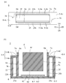
- the first integrated flow path 22 is formed by the partition wall 22 b and the second surface 4-2 of the first flow path member 4.
- the second integrated flow path 26 is formed by the partition wall 26 b and the second surface 4-2 of the first flow path member 4.
- the fourth surface 6-4 of the second flow path member 6 has a first part 6-4a, a second part 6-4b, and a third part 6-4c.
- the first part 6-4a is a part located on the first integrated flow path 22 and the second integrated flow path 26.
- the second part 6-4b is a part located on the partition wall 22b of the first integrated channel 22 and the partition wall 26b of the second integrated channel 26.
- the third part 6-4c is located outside the first opening 6d and is a part other than the first part 6-4a and the second part 6-4b.
- the raised portion 6e is provided so as to protrude upward from the fourth surface 6-4 of the second flow path member 6.
- the raised portion 6e is provided in the center of the second direction D2, the fifth direction D5, the third direction D3, and the sixth direction D6 of the fourth surface 6-4 of the second flow path member 6 in plan view.
- the outer periphery 7a of the raised portion 6e is located inside the outer periphery 7b of the fourth surface 6-4 in plan view. Further, the outer periphery of the first opening 6d is located inside the outer periphery 7a of the raised portion 6e.
- a method for connecting the first flow path member 4 and the second flow path member 6 will be described. First, an adhesive is applied to the third surface 6-3 of the second flow path member 6, and is superimposed on the second surface 4-2 of the first flow path member 4 while being aligned. Next, by using a predetermined jig, the fourth surface 6-4 of the second flow path member 6 is pressed to connect the first flow path member 4 and the second flow path member 6. Subsequently, while pressing the second flow path member 6, predetermined heat is applied to cure the adhesive, and the first flow path member 4 and the second flow path member 6 are connected.
- the second flow path member 6 when the second flow path member 6 is pressed from the fourth surface 6-4 side, since the raised portion 6e protrudes from the fourth surface 6-4, the first flow path member 4 and the second flow path member 4 In order to connect the member 6, it is necessary to simultaneously press both the fourth surface 6-4 and the upper surface of the raised portion 6e.
- the fourth surface 6-4 and the raised portion 6e are different in height, and may not be pressed with a uniform force. Accordingly, a uniform pressing force cannot be applied to the joint surface between the first flow path member 4 and the second flow path member 6, and the joint surface between the first flow path member 4 and the second flow path member 6 is sealed. May be worse.
- the outer periphery 7a of the raised portion 6e is located inside the outer periphery 7b of the fourth surface 6-4 in plan view. Therefore, in plan view, the fourth surface 6-4 of the second flow path member 6 surrounds the raised portion 6e. As a result, only the fourth surface 6-4 can be pressed to connect the first flow path member 4 and the second flow path member 6, and the first flow path member 4 and the second flow path member 6 A uniform pressing force can be applied to the joint surface. Therefore, the sealing performance between the first flow path member 4 and the second flow path member 6 can be improved.
- the outer periphery 7a of the raised portion 6e means the outer edge of the raised portion 6e when viewed in plan, and the outer periphery 7b of the fourth surface 6-4 is the fourth surface 6 when viewed in plan. -4 means the outer edge.
- the fourth surface 6-4 is formed with a first portion 6-4a located on the first integrated flow path 22 and the second integrated flow path 26 so as to be flush with each other.
- the first portion 6-4a located on the first integrated flow path 22 and the second integrated flow path 26 is formed flat. Accordingly, the pressing force generated when pressing the second flow path member 6 is uniformly applied to the first portion 6-4a provided on the fourth surface 6-4.
- the second flow path member 6 located between the first portion 6-4a and the openings 22a and 26a is hardly deformed, and the first integrated flow path 22 and the second integrated flow path 26 are deformed. It becomes difficult.
- the cross-sectional areas of the first integrated flow path 22 and the second integrated flow path 26 can be made constant, the pressure loss to each discharge unit 15 (see FIG. 7) can be made close to constant, and the discharge unit 15 variations in ejection characteristics can be reduced.
- the fourth surface 6-4 is formed with the second portion 6-4b located on the partition wall 22b of the first integrated channel 22 and the partition wall 26b of the second integrated channel 26 in a flush manner.
- the second portion 6-4b located on the partition wall 22b of the first integrated channel 22 and the partition wall 26b of the second integrated channel 26 is formed flat.
- first flow path member 4 and the second flow path are directly pressed against the joint surface between the first flow path member 4 and the second flow path member 6 serving as the bonding allowance.
- a uniform pressing force can be applied to the joint surface with the path member 6, and the sealing performance between the first flow path member 4 and the second flow path member 6 can be improved.
- the second flow path member 6 may warp or bend from the second direction D2 to the fifth direction D5. is there.
- the liquid discharge head 2 can firmly press the second part 6-4b by forming the second part 6-4b flush with each other. The sealing property with the two flow path members 6 can be enhanced.
- the second flow path member 6 is provided with a first opening 6d on the fourth surface 6-4, and the piezoelectric actuator substrate 40 is formed in the space formed by the first opening 6d and the first flow path member 4.
- a fourth surface 6-4 which is accommodated and located outside the first opening 6d, is formed flush.
- the fourth surface 6-4 positioned outside the first opening 6d is formed flat. Accordingly, a uniform pressing force can be applied to the joint surface between the first flow path member 4 and the second flow path member 6, and the space formed by the first opening 6 d and the first flow path member 4 is sealed. Can be stopped.
- the piezoelectric actuator substrate 40 when the piezoelectric actuator substrate 40 is disposed in the space, the piezoelectric actuator substrate 40 can be sealed, and the possibility that the liquid discharge head 2 is damaged can be reduced.
- the fourth surface 6-4, the first portion 6-4a, the second portion 6-4b, and the third portion 6-4c are formed to be flush with each other. It shows that the part 6-4a, the second part 6-4b, and the third part 6-4c are formed flat, and the flatness is 0.3 or less.
- the second flow path member 6 has a connecting portion 6f that connects the adjacent first through holes 6a. Therefore, a decrease in rigidity due to the provision of the first through hole 6a can be increased by the connecting portion 6f, and the second flow path member 6 is hardly deformed. Therefore, the flatness of the fourth surface 6-4 of the second flow path member 6 can be maintained, and the sealing performance between the first flow path member 4 and the second flow path member 6 can be improved.
- the connecting portion 6f is disposed above the piezoelectric actuator substrate 40, the piezoelectric actuator substrate 40 is covered with the connecting portion 6f, and ink or ink mist enters from above the second flow path member 6. Even so, it becomes difficult to leak into the piezoelectric actuator substrate 40.
- the signal transmission member 60 is drawn upward while being in contact with the raised portion 6e constituting the first through hole 6a. Therefore, the signal transmission member 60 is guided to the raised portion 6e and pulled out upward. As a result, the signal transmission member 60 can be easily pulled upward, and the productivity of the liquid ejection head 2 can be improved.
- liquid discharge head 2 showed the example which had the some 1st through-hole 6a, it is not limited to this.
- the liquid discharge head 2 may have only one first through hole 6a.
- the liquid discharge head 102 includes the first flow path member 4, the piezoelectric actuator substrate 40, the second flow path member 106, the housing 150, the heat radiating plate 152, and the elastic member 9.
- the second flow path member 106 has a third surface 106-3, a fourth surface 106-4, a first through hole 106a, and a raised portion 106e.
- the connecting portion 106f includes a first opening 106d that opens to the third surface 106-3 side and a second opening 106g that opens to the third surface 106-3 side.
- the second opening 106g is provided in communication with the first opening 106d.
- the connecting portion 106f includes a second opening 106g that opens to the third surface 106-3 side. Thereby, weight reduction of the 2nd flow path member 106 can be achieved, ensuring the rigidity of the 2nd flow path member 106. FIG. This is particularly useful when the liquid discharge head 102 is used in a serial printer.
- the width of the partition wall 106f between the first through hole 106a and the second opening 106g of the connecting portion 106f is equal to the width of the partition wall 22b of the first integrated channel 22 and the partition wall 26b of the second integrated channel 26.
- the partition 106f between the first through hole 106a and the second opening 106g of the connecting portion 106f, the partition 22b of the first integrated flow path 22, and the second 2 The resin filling speed of the partition wall 26b of the integrated flow path 26 can be made close to uniform.
- the second flow path member 106 that is less likely to cause variations in thickness in the connecting portion 106f, the partition wall 22b of the first integrated flow path 22, and the partition wall 26b of the second integrated flow path 26, and is less likely to be deformed. it can.
- the thickness of the partition walls 106f, 22b, and 26b is equal includes a manufacturing error and is a concept including a range of ⁇ 15%.
- the housing 150 is provided on the second flow path member 106, and is placed on the fourth surface 106-4 located outside the raised portion 106e. Therefore, the height of the liquid ejection head 102 can be reduced and the size of the liquid ejection head 102 can be reduced as compared with the case where the casing 150 is placed on the fourth surface 106-4 and the raised portion 106e. Can do.
- the fourth surface 106-4 is formed to be flush with each other, the housing 150 is stably placed. As a result, stress is less likely to concentrate at the joint between the housing 150 and the second flow path member 106, and the reliability of the liquid ejection head 102 can be improved.
- the elastic member 9 is provided adjacent to the outer periphery 107a of the raised portion 106e, and is provided so as to surround the outer periphery 107a while being in contact with the outer periphery 107a of the raised portion 106e. Therefore, when the casing 150 is joined to the second flow path member 106, the heat insulating part 150d is damaged by elastic deformation of the elastic member 9 even if the heat insulating part 150d is pressed by the second flow path member 106. The possibility can be reduced.
- the elastic member 9 is provided so as to be in contact with the outer periphery 107a of the raised portion 106e, the sealing performance between the raised portion 106e and the housing 150 can be improved.
- the elastic member 9 can be formed of, for example, a resin material.
- the elastic member 9 is in contact with the raised portion 106e and the fourth surface 106-4 of the second flow path member 106. Therefore, even if the casing 150 is pressed against the raised portion 106e and the fourth surface 106-4, the possibility of damage to the casing 150 can be reduced.
- the case 150 when the case 150 is joined to the second flow path member 106 or the heat sink 152 is joined to the case 150, the case 150 faces the raised portion 106e or the fourth surface 106-4. May be pressed. However, since the elastic member 9 is in contact with the raised portion 106e and the fourth surface 106-4 of the second flow path member 106, the casing 150 is not easily damaged.
- the elastic member 9 is also provided between the housing 150 and the heat sink 152. Accordingly, the possibility that the heat radiating plate 152 is damaged even when pressed by the raised portion 106e can be reduced, and the sealing performance of the opening 50a (see FIG. 2) of the housing 150 can be improved.
- the elastic member 9 may be formed by applying and curing an epoxy resin, or using a resin or metal O-ring.
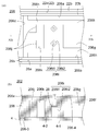
- the second flow path member 206 has a third surface 206-3, a fourth surface 206-4, a first through hole 206a, a raised portion 206e, and a connecting portion 206f.
- the connecting portion 206f includes a first opening 206d opened on the third surface 206-3 side, a second opening 206g opened on the third surface 206-3 side, a third opening 206k, and a second through hole 206i. I have.
- the second opening 206g is provided in communication with the first opening 206d.
- the third opening 206k is provided so as to communicate with the first opening 206d, and is provided apart from the second opening 206g.
- the third opening 206k is provided on the outer side in the second direction D2 and the outer side in the fifth direction D5 of the second opening 206g in plan view.
- the connecting portion 207f is provided with a third opening 206k outside the second opening 206g in plan view.
- the third opening 206k is provided outside the second opening 206g in the second direction D2 and outside in the fifth direction D5. Accordingly, when the second flow path member 206 is manufactured by injection molding, even if the resin is filled from the fifth direction D5 toward the second direction D2, it is difficult for a large amount of resin to flow to the connecting portion 207f. Accordingly, the resin is less likely to be insufficient in the partition wall 206h formed by the first through hole 206a and the second opening 206g, the partition wall 22b of the first integrated channel 22 and the partition wall 26b of the second integrated channel 26.
- the resin that has flowed from the fifth direction D5 toward the second direction D2 easily flows into the connecting portion 206f having a large cross-sectional area, but the third opening 206k causes the disconnection of the partition wall 206h of the connecting portion 206f.
- the area can be made close to the cross-sectional area of the partition walls 22b and 26b, and the resin filling speed in the vicinity of the third opening 206k can be made close to uniform.
- the third opening 206k may not be provided on the outer side in the second direction D2 and the outer side in the fifth direction D5 of the second opening 206g in plan view, and the third opening 206k may be made of resin more than the second opening 206g. What is necessary is just to be provided in the upstream of the filling direction.
- the wall constituting the third opening 206k has a recess 206j located on the opposite side to the second opening 206g.
- the second through hole 206i is provided so as to communicate with the first opening 206d, and is provided apart from the second opening 206g and the third opening 206k.
- the second through hole 206i is provided between the second opening 206g and the third opening 206k.
- the second through hole 206i has a first part 206i1 and a second part 206i2.
- the first portion 206i1 is provided from the raised portion 206e of the second flow path member 206 toward the inside.
- the second portion 206 i 2 is provided from the first opening 206 d of the second flow path member 206 toward the inside.
- the first part 206i1 and the second part 206i2 are provided so as to communicate with each other.
- the first part 206i1 has a circular shape in plan view.
- the second portion 206i2 has a rectangular shape in plan view. In plan view, the second portion 206i2 has a vertex whose sides intersect, and the vertex is positioned so as to face the second direction D2.
- part 206i2 is formed longer than the diameter of the 1st site
- the fixing member 28 is accommodated in the second portion 206i2.
- a nut or the like can be used, and a screw inserted from the protruding portion 206e side is screwed. Thereby, the member provided on the second flow path member 206 can be fixed to the second flow path member 206.
- the apex of the second portion 206i2 is positioned so as to face the second direction D2. For this reason, when the second flow path member 206 is manufactured by injection molding, the flow of the supplied resin is less likely to be hindered by the second through hole 206i. That is, the supplied resin collides with the apex, and then flows along the side of the second part 206i2 to the partition wall 206h between the first through hole 206a and the second opening 206g. As a result, the resin can be smoothly supplied to the partition wall 206h between the first through hole 206a and the second opening 206g. Therefore, the amount of resin supplied to the partition wall 206h is not easily insufficient.
- part 206i2 should just be polygonal shape in planar view, and is not limited to a rectangular shape. For example, it may be hexagonal. Further, the second through-hole 206i may not have the first part 206i1 and the second part 206i2, and may have a polygonal column shape.
- the actuator substrate 40 is exemplified as the pressurizing member, but is not limited thereto.
- a heating member may be provided for each pressurizing chamber 10, and a pressure member that heats the liquid inside the pressurizing chamber 10 with the heat of the heat generating portion and pressurizes the liquid by thermal expansion.
- the substrate discharge head 2 has shown the configuration in which the liquid is supplied from the through hole 6b of the second flow path member 6 and the liquid that has not been discharged from the through hole 6c is recovered, the present invention is not limited to this.
- it is good also as a structure which collects the liquid which supplied the liquid from the through-hole 6c of the 2nd flow-path member 6, and was not discharged from the through-hole 6b.
Landscapes
- Engineering & Computer Science (AREA)
- Quality & Reliability (AREA)
- Particle Formation And Scattering Control In Inkjet Printers (AREA)
- Ink Jet (AREA)
Priority Applications (9)
| Application Number | Priority Date | Filing Date | Title |
|---|---|---|---|
| US15/576,990 US10293608B2 (en) | 2015-05-27 | 2016-05-27 | Liquid ejection head and recording device |
| EP16800117.0A EP3290209B1 (en) | 2015-05-27 | 2016-05-27 | Liquid ejection head and recording device |
| CN201680030640.4A CN107683208B (zh) | 2015-05-27 | 2016-05-27 | 液体喷出头以及记录装置 |
| JP2017520811A JP6486465B2 (ja) | 2015-05-27 | 2016-05-27 | 液体吐出ヘッド、および記録装置 |
| US16/392,210 US10751995B2 (en) | 2015-05-27 | 2019-04-23 | Liquid ejection head and recording device |
| US17/000,137 US11351780B2 (en) | 2015-05-27 | 2020-08-21 | Liquid ejection head and recording device |
| US17/739,881 US11787178B2 (en) | 2015-05-27 | 2022-05-09 | Liquid ejection head and recording device |
| US18/368,343 US12122158B2 (en) | 2015-05-27 | 2023-09-14 | Liquid ejection head and recording device |
| US18/890,329 US20250010610A1 (en) | 2015-05-27 | 2024-09-19 | Liquid ejection head and recording device |
Applications Claiming Priority (2)
| Application Number | Priority Date | Filing Date | Title |
|---|---|---|---|
| JP2015107616 | 2015-05-27 | ||
| JP2015-107616 | 2015-05-27 |
Related Child Applications (2)
| Application Number | Title | Priority Date | Filing Date |
|---|---|---|---|
| US15/576,990 A-371-Of-International US10293608B2 (en) | 2015-05-27 | 2016-05-27 | Liquid ejection head and recording device |
| US16/392,210 Continuation US10751995B2 (en) | 2015-05-27 | 2019-04-23 | Liquid ejection head and recording device |
Publications (1)
| Publication Number | Publication Date |
|---|---|
| WO2016190413A1 true WO2016190413A1 (ja) | 2016-12-01 |
Family
ID=57393312
Family Applications (1)
| Application Number | Title | Priority Date | Filing Date |
|---|---|---|---|
| PCT/JP2016/065706 Ceased WO2016190413A1 (ja) | 2015-05-27 | 2016-05-27 | 液体吐出ヘッド、および記録装置 |
Country Status (5)
| Country | Link |
|---|---|
| US (6) | US10293608B2 (enExample) |
| EP (1) | EP3290209B1 (enExample) |
| JP (7) | JP6486465B2 (enExample) |
| CN (2) | CN110356114B (enExample) |
| WO (1) | WO2016190413A1 (enExample) |
Cited By (3)
| Publication number | Priority date | Publication date | Assignee | Title |
|---|---|---|---|---|
| WO2023190923A1 (ja) * | 2022-03-30 | 2023-10-05 | 京セラ株式会社 | 液体吐出ヘッドおよび記録装置 |
| JPWO2024157956A1 (enExample) * | 2023-01-23 | 2024-08-02 | ||
| WO2025089296A1 (ja) * | 2023-10-24 | 2025-05-01 | 京セラ株式会社 | 液体吐出ヘッド及び記録装置 |
Families Citing this family (2)
| Publication number | Priority date | Publication date | Assignee | Title |
|---|---|---|---|---|
| CN107107612B (zh) | 2014-12-25 | 2019-09-03 | 京瓷株式会社 | 液体喷出头以及记录装置 |
| CN110356114B (zh) * | 2015-05-27 | 2021-08-13 | 京瓷株式会社 | 液体喷出头以及记录装置 |
Citations (3)
| Publication number | Priority date | Publication date | Assignee | Title |
|---|---|---|---|---|
| JP2002079682A (ja) * | 2000-09-06 | 2002-03-19 | Canon Inc | インクジェット記録ヘッドおよび該インクジェット記録ヘッドの製造方法 |
| JP2004291484A (ja) * | 2003-03-27 | 2004-10-21 | Seiko Epson Corp | 液体噴射ヘッドの製造方法および同製造方法で製造された液体噴射ヘッドならびに製造用金型 |
| JP2010201937A (ja) * | 2010-05-19 | 2010-09-16 | Seiko Epson Corp | 液体噴射装置の製造方法および液体噴射装置 |
Family Cites Families (68)
| Publication number | Priority date | Publication date | Assignee | Title |
|---|---|---|---|---|
| US5565900A (en) * | 1994-02-04 | 1996-10-15 | Hewlett-Packard Company | Unit print head assembly for ink-jet printing |
| JP3879297B2 (ja) | 1999-01-21 | 2007-02-07 | セイコーエプソン株式会社 | インクジェット式記録ヘッド |
| JP2001232788A (ja) | 2000-02-25 | 2001-08-28 | Seiko Instruments Inc | インクジェットヘッド |
| DE60122981T2 (de) | 2000-07-10 | 2007-09-06 | Canon K.K. | Flüssigkeitsstrahlaufzeichnungskopfkartusche |
| US6981760B2 (en) | 2001-09-27 | 2006-01-03 | Fuji Photo Film Co., Ltd. | Ink jet head and ink jet printer |
| US7044591B2 (en) * | 2002-09-25 | 2006-05-16 | Brother Kogya Kabushiki Kaisha | Ink-jet head, filter assembly used for manufacturing the ink-jet head, and method for manufacturing the ink-jet head using the filter assembly |
| JP3925406B2 (ja) * | 2002-12-26 | 2007-06-06 | セイコーエプソン株式会社 | 液体噴射ヘッド |
| US6908170B2 (en) | 2003-06-23 | 2005-06-21 | Fuji Xerox Co., Ltd. | Devices for dissipating heat in a fluid ejector head and methods for making such devices |
| JP4446708B2 (ja) * | 2003-10-10 | 2010-04-07 | 株式会社リコー | 液滴吐出ヘッド、液体吐出装置及び画像形成装置 |
| JP4517642B2 (ja) | 2003-12-24 | 2010-08-04 | コニカミノルタホールディングス株式会社 | インクジェットヘッド |
| JP4182901B2 (ja) * | 2004-02-27 | 2008-11-19 | ブラザー工業株式会社 | インクジェットヘッド |
| JP2005246656A (ja) * | 2004-03-02 | 2005-09-15 | Ricoh Co Ltd | 液滴吐出ヘッド、液体吐出装置及び画像形成装置 |
| JP2007069532A (ja) * | 2005-09-08 | 2007-03-22 | Fujifilm Corp | 液体吐出ヘッドの製造方法及び画像形成装置 |
| JP2007118309A (ja) * | 2005-10-26 | 2007-05-17 | Fujifilm Corp | インクジェット記録ヘッド及びこれを備えた画像形成装置 |
| EP1997637B1 (en) * | 2007-05-30 | 2012-09-12 | Océ-Technologies B.V. | Method of manufacturing a piezoelectric ink jet device |
| JP5256771B2 (ja) * | 2008-02-23 | 2013-08-07 | 株式会社リコー | 液滴吐出ヘッド、インクカートリッジ及び画像形成装置 |
| JP2009226923A (ja) * | 2008-02-26 | 2009-10-08 | Seiko Epson Corp | 液体噴射ヘッド及び液体噴射装置並びにアクチュエータ装置 |
| JP4961373B2 (ja) * | 2008-03-12 | 2012-06-27 | 株式会社リコー | 液体吐出ヘッド及び画像形成装置 |
| KR101256855B1 (ko) * | 2008-05-22 | 2013-04-22 | 후지필름 가부시키가이샤 | 다이와 집적 회로 소자를 갖는 액추에이팅 가능한 장치 |
| CN102026813B (zh) * | 2008-05-23 | 2015-05-27 | 富士胶片株式会社 | 流体液滴喷射装置 |
| JP5206164B2 (ja) | 2008-07-02 | 2013-06-12 | ブラザー工業株式会社 | ヘッドユニット及びこれを備えた液体吐出装置 |
| JP5342933B2 (ja) | 2009-06-09 | 2013-11-13 | 理想科学工業株式会社 | 画像形成装置 |
| CN101954334B (zh) * | 2009-07-14 | 2013-07-03 | 鸿富锦精密工业(深圳)有限公司 | 压电微粒雾化器 |
| JP5475389B2 (ja) | 2009-10-08 | 2014-04-16 | 富士フイルム株式会社 | 液滴吐出ヘッド、該液滴吐出ヘッドを有する液滴吐出装置、および、該液滴吐出ヘッドに気泡を溜める方法 |
| JP5388834B2 (ja) * | 2009-12-24 | 2014-01-15 | 京セラ株式会社 | 液体吐出ヘッドおよびそれを用いた記録装置 |
| US8317302B2 (en) * | 2010-03-18 | 2012-11-27 | Fujifilm Corporation | Restriction of fluid ejector membrane |
| JP5753739B2 (ja) * | 2010-06-28 | 2015-07-22 | 富士フイルム株式会社 | 液滴吐出ヘッド |
| JP5495385B2 (ja) | 2010-06-30 | 2014-05-21 | 富士フイルム株式会社 | 液滴吐出ヘッド |
| JP5729386B2 (ja) * | 2010-07-02 | 2015-06-03 | コニカミノルタ株式会社 | インクジェットヘッド |
| JP5936094B2 (ja) * | 2010-09-16 | 2016-06-15 | 株式会社リコー | 液滴吐出ヘッド、液滴吐出装置及び画像形成装置 |
| US8657420B2 (en) | 2010-12-28 | 2014-02-25 | Fujifilm Corporation | Fluid recirculation in droplet ejection devices |
| JP5750753B2 (ja) | 2011-01-11 | 2015-07-22 | セイコーエプソン株式会社 | 液体噴射ヘッド及び液体噴射装置 |
| JP5699696B2 (ja) * | 2011-03-07 | 2015-04-15 | 株式会社リコー | 液体吐出ヘッド及び画像形成装置 |
| JP5743070B2 (ja) * | 2011-03-23 | 2015-07-01 | セイコーエプソン株式会社 | 液体噴射ヘッド及び液体噴射装置 |
| JP5837925B2 (ja) * | 2011-05-28 | 2015-12-24 | 京セラ株式会社 | 液体吐出ヘッドおよびそれを用いた記録装置 |
| JP2012250503A (ja) * | 2011-06-06 | 2012-12-20 | Fujifilm Corp | 液滴吐出ヘッド |
| JP5769560B2 (ja) * | 2011-09-09 | 2015-08-26 | キヤノン株式会社 | 液体吐出ヘッド用基体及びその製造方法 |
| JP5587268B2 (ja) * | 2011-09-22 | 2014-09-10 | 富士フイルム株式会社 | インクジェットヘッド及びその製造方法 |
| JP5352652B2 (ja) | 2011-09-26 | 2013-11-27 | 東芝テック株式会社 | インクジェットヘッド |
| JP6128820B2 (ja) * | 2011-12-22 | 2017-05-17 | キヤノン株式会社 | 液体吐出ヘッド |
| JP5615307B2 (ja) * | 2012-02-14 | 2014-10-29 | 富士フイルム株式会社 | 液滴吐出装置 |
| JP2013176883A (ja) * | 2012-02-28 | 2013-09-09 | Kyocera Corp | 液体吐出ヘッドおよびそれを用いた記録装置 |
| JP2013180405A (ja) | 2012-02-29 | 2013-09-12 | Kyocera Corp | 液体吐出ヘッドおよびそれを用いた記録装置 |
| JP5908808B2 (ja) | 2012-07-31 | 2016-04-26 | 京セラ株式会社 | 液体供給装置、液体吐出ヘッド、および記録装置 |
| JP2014046627A (ja) * | 2012-09-01 | 2014-03-17 | Ricoh Co Ltd | 液体吐出ヘッドの製造方法、液体吐出ヘッド及び画像形成装置 |
| JP6090560B2 (ja) * | 2012-10-12 | 2017-03-08 | セイコーエプソン株式会社 | 液体噴射装置 |
| JP5956319B2 (ja) | 2012-11-29 | 2016-07-27 | 京セラ株式会社 | 液体吐出ヘッド、およびそれを用いた記録装置 |
| JP6034207B2 (ja) * | 2013-01-28 | 2016-11-30 | 京セラ株式会社 | 液体吐出ヘッド、および記録装置 |
| JP2014162076A (ja) | 2013-02-23 | 2014-09-08 | Kyocera Corp | 液体吐出ヘッド、および記録装置 |
| JP2014162192A (ja) * | 2013-02-27 | 2014-09-08 | Ricoh Co Ltd | 液体吐出ヘッド及び画像形成装置 |
| JP2014172323A (ja) * | 2013-03-11 | 2014-09-22 | Toshiba Tec Corp | インクジェットヘッドおよびインクジェット記録装置 |
| JP5982559B2 (ja) * | 2013-03-26 | 2016-08-31 | 京セラ株式会社 | 液体吐出ヘッド、およびそれを用いた記録装置 |
| JP6197448B2 (ja) * | 2013-03-27 | 2017-09-20 | セイコーエプソン株式会社 | 液体噴射ヘッドおよび液体噴射装置 |
| JP6276103B2 (ja) | 2013-04-26 | 2018-02-07 | 京セラ株式会社 | 液体吐出ヘッドおよび記録装置 |
| WO2014203705A1 (ja) * | 2013-06-21 | 2014-12-24 | 京セラ株式会社 | 液体吐出ヘッドおよび記録装置 |
| JP2015033799A (ja) * | 2013-08-09 | 2015-02-19 | セイコーエプソン株式会社 | 液体噴射ヘッド、および、液体噴射装置 |
| JP6075558B2 (ja) * | 2013-08-20 | 2017-02-08 | セイコーエプソン株式会社 | 液体噴射ヘッドの製造方法 |
| JP6291761B2 (ja) | 2013-09-19 | 2018-03-14 | セイコーエプソン株式会社 | 印刷装置 |
| JP5826304B2 (ja) * | 2014-01-27 | 2015-12-02 | 京セラ株式会社 | 液体吐出ヘッドおよびそれを用いた記録装置 |
| WO2015125865A1 (ja) * | 2014-02-19 | 2015-08-27 | 京セラ株式会社 | 液体吐出ヘッド、およびそれを用いた記録装置 |
| JP6270533B2 (ja) * | 2014-02-25 | 2018-01-31 | キヤノン株式会社 | 液体吐出ヘッド、記録装置、および液体吐出ヘッドの放熱方法 |
| US9421768B2 (en) * | 2014-04-02 | 2016-08-23 | Kabushiki Kaisha Toshiba | Inkjet printer head |
| EP3162567B1 (en) * | 2014-06-27 | 2020-09-23 | KYOCERA Corporation | Flow channel member, liquid discharge head, and recording device |
| JP6345006B2 (ja) | 2014-07-08 | 2018-06-20 | キヤノン株式会社 | インクジェット記録ヘッド用基板の製造方法 |
| CN107107612B (zh) | 2014-12-25 | 2019-09-03 | 京瓷株式会社 | 液体喷出头以及记录装置 |
| JP7016208B2 (ja) | 2014-12-27 | 2022-02-04 | 株式会社リコー | 液体吐出ヘッド、液体吐出ユニット、液体を吐出する装置 |
| ES2716122T3 (es) * | 2015-01-06 | 2019-06-10 | Ricoh Co Ltd | Cabezal de descarga de líquido, unidad de descarga de líquido y dispositivo para descargar líquido |
| CN110356114B (zh) * | 2015-05-27 | 2021-08-13 | 京瓷株式会社 | 液体喷出头以及记录装置 |
-
2016
- 2016-05-27 CN CN201910798943.6A patent/CN110356114B/zh active Active
- 2016-05-27 EP EP16800117.0A patent/EP3290209B1/en active Active
- 2016-05-27 US US15/576,990 patent/US10293608B2/en active Active
- 2016-05-27 WO PCT/JP2016/065706 patent/WO2016190413A1/ja not_active Ceased
- 2016-05-27 CN CN201680030640.4A patent/CN107683208B/zh active Active
- 2016-05-27 JP JP2017520811A patent/JP6486465B2/ja active Active
-
2019
- 2019-02-19 JP JP2019027031A patent/JP6913120B2/ja active Active
- 2019-04-23 US US16/392,210 patent/US10751995B2/en active Active
-
2020
- 2020-08-21 US US17/000,137 patent/US11351780B2/en active Active
- 2020-09-01 JP JP2020146787A patent/JP6952850B2/ja active Active
-
2021
- 2021-09-28 JP JP2021157891A patent/JP7197658B2/ja active Active
-
2022
- 2022-05-09 US US17/739,881 patent/US11787178B2/en active Active
- 2022-12-15 JP JP2022199898A patent/JP7352716B2/ja active Active
-
2023
- 2023-09-14 US US18/368,343 patent/US12122158B2/en active Active
- 2023-09-15 JP JP2023149891A patent/JP7723708B2/ja active Active
-
2024
- 2024-09-19 US US18/890,329 patent/US20250010610A1/en active Pending
-
2025
- 2025-05-02 JP JP2025076673A patent/JP2025111788A/ja active Pending
Patent Citations (3)
| Publication number | Priority date | Publication date | Assignee | Title |
|---|---|---|---|---|
| JP2002079682A (ja) * | 2000-09-06 | 2002-03-19 | Canon Inc | インクジェット記録ヘッドおよび該インクジェット記録ヘッドの製造方法 |
| JP2004291484A (ja) * | 2003-03-27 | 2004-10-21 | Seiko Epson Corp | 液体噴射ヘッドの製造方法および同製造方法で製造された液体噴射ヘッドならびに製造用金型 |
| JP2010201937A (ja) * | 2010-05-19 | 2010-09-16 | Seiko Epson Corp | 液体噴射装置の製造方法および液体噴射装置 |
Cited By (6)
| Publication number | Priority date | Publication date | Assignee | Title |
|---|---|---|---|---|
| WO2023190923A1 (ja) * | 2022-03-30 | 2023-10-05 | 京セラ株式会社 | 液体吐出ヘッドおよび記録装置 |
| JPWO2023190923A1 (enExample) * | 2022-03-30 | 2023-10-05 | ||
| JP7730416B2 (ja) | 2022-03-30 | 2025-08-27 | 京セラ株式会社 | 液体吐出ヘッドおよび記録装置 |
| JPWO2024157956A1 (enExample) * | 2023-01-23 | 2024-08-02 | ||
| JP7649927B2 (ja) | 2023-01-23 | 2025-03-21 | 京セラ株式会社 | 液滴吐出ヘッドおよび液滴吐出装置 |
| WO2025089296A1 (ja) * | 2023-10-24 | 2025-05-01 | 京セラ株式会社 | 液体吐出ヘッド及び記録装置 |
Also Published As
| Publication number | Publication date |
|---|---|
| JP2019089349A (ja) | 2019-06-13 |
| US20220332114A1 (en) | 2022-10-20 |
| JP7197658B2 (ja) | 2022-12-27 |
| US12122158B2 (en) | 2024-10-22 |
| JP2025111788A (ja) | 2025-07-30 |
| JP2023025267A (ja) | 2023-02-21 |
| JP6913120B2 (ja) | 2021-08-04 |
| US20250010610A1 (en) | 2025-01-09 |
| JPWO2016190413A1 (ja) | 2018-03-15 |
| JP7352716B2 (ja) | 2023-09-28 |
| US20240001671A1 (en) | 2024-01-04 |
| US11787178B2 (en) | 2023-10-17 |
| JP6952850B2 (ja) | 2021-10-27 |
| CN110356114A (zh) | 2019-10-22 |
| US11351780B2 (en) | 2022-06-07 |
| US20190263118A1 (en) | 2019-08-29 |
| JP2023169293A (ja) | 2023-11-29 |
| JP2022001444A (ja) | 2022-01-06 |
| EP3290209B1 (en) | 2019-06-26 |
| CN107683208B (zh) | 2019-09-24 |
| US20180147846A1 (en) | 2018-05-31 |
| EP3290209A1 (en) | 2018-03-07 |
| US10751995B2 (en) | 2020-08-25 |
| JP6486465B2 (ja) | 2019-03-20 |
| US10293608B2 (en) | 2019-05-21 |
| JP2020199773A (ja) | 2020-12-17 |
| CN110356114B (zh) | 2021-08-13 |
| CN107683208A (zh) | 2018-02-09 |
| EP3290209A4 (en) | 2018-04-18 |
| US20210070045A1 (en) | 2021-03-11 |
| JP7723708B2 (ja) | 2025-08-14 |
Similar Documents
| Publication | Publication Date | Title |
|---|---|---|
| JP7197658B2 (ja) | 液体吐出ヘッド、および記録装置 | |
| JP6317442B2 (ja) | 流路部材、液体吐出ヘッド、および記録装置 | |
| JP6209671B2 (ja) | 液体吐出ヘッド、およびそれを用いた記録装置 | |
| JP6298929B2 (ja) | 液体吐出ヘッド、および記録装置 | |
| JP6340478B2 (ja) | 液体吐出ヘッド、および記録装置 |
Legal Events
| Date | Code | Title | Description |
|---|---|---|---|
| 121 | Ep: the epo has been informed by wipo that ep was designated in this application |
Ref document number: 16800117 Country of ref document: EP Kind code of ref document: A1 |
|
| ENP | Entry into the national phase |
Ref document number: 2017520811 Country of ref document: JP Kind code of ref document: A |
|
| WWE | Wipo information: entry into national phase |
Ref document number: 15576990 Country of ref document: US |
|
| NENP | Non-entry into the national phase |
Ref country code: DE |