EP3290209B1 - Liquid ejection head and recording device - Google Patents
Liquid ejection head and recording device Download PDFInfo
- Publication number
- EP3290209B1 EP3290209B1 EP16800117.0A EP16800117A EP3290209B1 EP 3290209 B1 EP3290209 B1 EP 3290209B1 EP 16800117 A EP16800117 A EP 16800117A EP 3290209 B1 EP3290209 B1 EP 3290209B1
- Authority
- EP
- European Patent Office
- Prior art keywords
- liquid ejection
- ejection head
- channel
- channel member
- opening
- Prior art date
- Legal status (The legal status is an assumption and is not a legal conclusion. Google has not performed a legal analysis and makes no representation as to the accuracy of the status listed.)
- Active
Links
Images


Classifications
-
- B—PERFORMING OPERATIONS; TRANSPORTING
- B41—PRINTING; LINING MACHINES; TYPEWRITERS; STAMPS
- B41J—TYPEWRITERS; SELECTIVE PRINTING MECHANISMS, i.e. MECHANISMS PRINTING OTHERWISE THAN FROM A FORME; CORRECTION OF TYPOGRAPHICAL ERRORS
- B41J2/00—Typewriters or selective printing mechanisms characterised by the printing or marking process for which they are designed
- B41J2/005—Typewriters or selective printing mechanisms characterised by the printing or marking process for which they are designed characterised by bringing liquid or particles selectively into contact with a printing material
- B41J2/01—Ink jet
- B41J2/135—Nozzles
- B41J2/14—Structure thereof only for on-demand ink jet heads
- B41J2/14201—Structure of print heads with piezoelectric elements
-
- B—PERFORMING OPERATIONS; TRANSPORTING
- B41—PRINTING; LINING MACHINES; TYPEWRITERS; STAMPS
- B41J—TYPEWRITERS; SELECTIVE PRINTING MECHANISMS, i.e. MECHANISMS PRINTING OTHERWISE THAN FROM A FORME; CORRECTION OF TYPOGRAPHICAL ERRORS
- B41J2/00—Typewriters or selective printing mechanisms characterised by the printing or marking process for which they are designed
- B41J2/005—Typewriters or selective printing mechanisms characterised by the printing or marking process for which they are designed characterised by bringing liquid or particles selectively into contact with a printing material
- B41J2/01—Ink jet
- B41J2/135—Nozzles
- B41J2/14—Structure thereof only for on-demand ink jet heads
- B41J2/14201—Structure of print heads with piezoelectric elements
- B41J2/14209—Structure of print heads with piezoelectric elements of finger type, chamber walls consisting integrally of piezoelectric material
-
- B—PERFORMING OPERATIONS; TRANSPORTING
- B41—PRINTING; LINING MACHINES; TYPEWRITERS; STAMPS
- B41J—TYPEWRITERS; SELECTIVE PRINTING MECHANISMS, i.e. MECHANISMS PRINTING OTHERWISE THAN FROM A FORME; CORRECTION OF TYPOGRAPHICAL ERRORS
- B41J2/00—Typewriters or selective printing mechanisms characterised by the printing or marking process for which they are designed
- B41J2/005—Typewriters or selective printing mechanisms characterised by the printing or marking process for which they are designed characterised by bringing liquid or particles selectively into contact with a printing material
- B41J2/01—Ink jet
- B41J2/015—Ink jet characterised by the jet generation process
- B41J2/04—Ink jet characterised by the jet generation process generating single droplets or particles on demand
- B41J2/045—Ink jet characterised by the jet generation process generating single droplets or particles on demand by pressure, e.g. electromechanical transducers
- B41J2/04501—Control methods or devices therefor, e.g. driver circuits, control circuits
-
- B—PERFORMING OPERATIONS; TRANSPORTING
- B41—PRINTING; LINING MACHINES; TYPEWRITERS; STAMPS
- B41J—TYPEWRITERS; SELECTIVE PRINTING MECHANISMS, i.e. MECHANISMS PRINTING OTHERWISE THAN FROM A FORME; CORRECTION OF TYPOGRAPHICAL ERRORS
- B41J2/00—Typewriters or selective printing mechanisms characterised by the printing or marking process for which they are designed
- B41J2/005—Typewriters or selective printing mechanisms characterised by the printing or marking process for which they are designed characterised by bringing liquid or particles selectively into contact with a printing material
- B41J2/01—Ink jet
- B41J2/135—Nozzles
- B41J2/14—Structure thereof only for on-demand ink jet heads
- B41J2/14016—Structure of bubble jet print heads
- B41J2/14024—Assembling head parts
-
- B—PERFORMING OPERATIONS; TRANSPORTING
- B41—PRINTING; LINING MACHINES; TYPEWRITERS; STAMPS
- B41J—TYPEWRITERS; SELECTIVE PRINTING MECHANISMS, i.e. MECHANISMS PRINTING OTHERWISE THAN FROM A FORME; CORRECTION OF TYPOGRAPHICAL ERRORS
- B41J2/00—Typewriters or selective printing mechanisms characterised by the printing or marking process for which they are designed
- B41J2/005—Typewriters or selective printing mechanisms characterised by the printing or marking process for which they are designed characterised by bringing liquid or particles selectively into contact with a printing material
- B41J2/01—Ink jet
- B41J2/135—Nozzles
- B41J2/14—Structure thereof only for on-demand ink jet heads
- B41J2/14201—Structure of print heads with piezoelectric elements
- B41J2/14233—Structure of print heads with piezoelectric elements of film type, deformed by bending and disposed on a diaphragm
-
- B—PERFORMING OPERATIONS; TRANSPORTING
- B41—PRINTING; LINING MACHINES; TYPEWRITERS; STAMPS
- B41J—TYPEWRITERS; SELECTIVE PRINTING MECHANISMS, i.e. MECHANISMS PRINTING OTHERWISE THAN FROM A FORME; CORRECTION OF TYPOGRAPHICAL ERRORS
- B41J2/00—Typewriters or selective printing mechanisms characterised by the printing or marking process for which they are designed
- B41J2/005—Typewriters or selective printing mechanisms characterised by the printing or marking process for which they are designed characterised by bringing liquid or particles selectively into contact with a printing material
- B41J2/01—Ink jet
- B41J2/17—Ink jet characterised by ink handling
- B41J2/175—Ink supply systems ; Circuit parts therefor
- B41J2/17566—Ink level or ink residue control
-
- B—PERFORMING OPERATIONS; TRANSPORTING
- B41—PRINTING; LINING MACHINES; TYPEWRITERS; STAMPS
- B41J—TYPEWRITERS; SELECTIVE PRINTING MECHANISMS, i.e. MECHANISMS PRINTING OTHERWISE THAN FROM A FORME; CORRECTION OF TYPOGRAPHICAL ERRORS
- B41J2/00—Typewriters or selective printing mechanisms characterised by the printing or marking process for which they are designed
- B41J2/005—Typewriters or selective printing mechanisms characterised by the printing or marking process for which they are designed characterised by bringing liquid or particles selectively into contact with a printing material
- B41J2/01—Ink jet
- B41J2/17—Ink jet characterised by ink handling
- B41J2/195—Ink jet characterised by ink handling for monitoring ink quality
-
- B—PERFORMING OPERATIONS; TRANSPORTING
- B41—PRINTING; LINING MACHINES; TYPEWRITERS; STAMPS
- B41J—TYPEWRITERS; SELECTIVE PRINTING MECHANISMS, i.e. MECHANISMS PRINTING OTHERWISE THAN FROM A FORME; CORRECTION OF TYPOGRAPHICAL ERRORS
- B41J2/00—Typewriters or selective printing mechanisms characterised by the printing or marking process for which they are designed
- B41J2/005—Typewriters or selective printing mechanisms characterised by the printing or marking process for which they are designed characterised by bringing liquid or particles selectively into contact with a printing material
- B41J2/01—Ink jet
- B41J2/21—Ink jet for multi-colour printing
-
- B—PERFORMING OPERATIONS; TRANSPORTING
- B41—PRINTING; LINING MACHINES; TYPEWRITERS; STAMPS
- B41J—TYPEWRITERS; SELECTIVE PRINTING MECHANISMS, i.e. MECHANISMS PRINTING OTHERWISE THAN FROM A FORME; CORRECTION OF TYPOGRAPHICAL ERRORS
- B41J2/00—Typewriters or selective printing mechanisms characterised by the printing or marking process for which they are designed
- B41J2/22—Typewriters or selective printing mechanisms characterised by the printing or marking process for which they are designed characterised by selective application of impact or pressure on a printing material or impression-transfer material
- B41J2/23—Typewriters or selective printing mechanisms characterised by the printing or marking process for which they are designed characterised by selective application of impact or pressure on a printing material or impression-transfer material using print wires
- B41J2/305—Ink supply apparatus
-
- B—PERFORMING OPERATIONS; TRANSPORTING
- B41—PRINTING; LINING MACHINES; TYPEWRITERS; STAMPS
- B41J—TYPEWRITERS; SELECTIVE PRINTING MECHANISMS, i.e. MECHANISMS PRINTING OTHERWISE THAN FROM A FORME; CORRECTION OF TYPOGRAPHICAL ERRORS
- B41J2/00—Typewriters or selective printing mechanisms characterised by the printing or marking process for which they are designed
- B41J2/005—Typewriters or selective printing mechanisms characterised by the printing or marking process for which they are designed characterised by bringing liquid or particles selectively into contact with a printing material
- B41J2/01—Ink jet
- B41J2/135—Nozzles
- B41J2/14—Structure thereof only for on-demand ink jet heads
- B41J2/14201—Structure of print heads with piezoelectric elements
- B41J2/14209—Structure of print heads with piezoelectric elements of finger type, chamber walls consisting integrally of piezoelectric material
- B41J2002/14225—Finger type piezoelectric element on only one side of the chamber
-
- B—PERFORMING OPERATIONS; TRANSPORTING
- B41—PRINTING; LINING MACHINES; TYPEWRITERS; STAMPS
- B41J—TYPEWRITERS; SELECTIVE PRINTING MECHANISMS, i.e. MECHANISMS PRINTING OTHERWISE THAN FROM A FORME; CORRECTION OF TYPOGRAPHICAL ERRORS
- B41J2/00—Typewriters or selective printing mechanisms characterised by the printing or marking process for which they are designed
- B41J2/005—Typewriters or selective printing mechanisms characterised by the printing or marking process for which they are designed characterised by bringing liquid or particles selectively into contact with a printing material
- B41J2/01—Ink jet
- B41J2/135—Nozzles
- B41J2/14—Structure thereof only for on-demand ink jet heads
- B41J2002/14322—Print head without nozzle
-
- B—PERFORMING OPERATIONS; TRANSPORTING
- B41—PRINTING; LINING MACHINES; TYPEWRITERS; STAMPS
- B41J—TYPEWRITERS; SELECTIVE PRINTING MECHANISMS, i.e. MECHANISMS PRINTING OTHERWISE THAN FROM A FORME; CORRECTION OF TYPOGRAPHICAL ERRORS
- B41J2/00—Typewriters or selective printing mechanisms characterised by the printing or marking process for which they are designed
- B41J2/005—Typewriters or selective printing mechanisms characterised by the printing or marking process for which they are designed characterised by bringing liquid or particles selectively into contact with a printing material
- B41J2/01—Ink jet
- B41J2/135—Nozzles
- B41J2/14—Structure thereof only for on-demand ink jet heads
- B41J2002/14362—Assembling elements of heads
-
- B—PERFORMING OPERATIONS; TRANSPORTING
- B41—PRINTING; LINING MACHINES; TYPEWRITERS; STAMPS
- B41J—TYPEWRITERS; SELECTIVE PRINTING MECHANISMS, i.e. MECHANISMS PRINTING OTHERWISE THAN FROM A FORME; CORRECTION OF TYPOGRAPHICAL ERRORS
- B41J2/00—Typewriters or selective printing mechanisms characterised by the printing or marking process for which they are designed
- B41J2/005—Typewriters or selective printing mechanisms characterised by the printing or marking process for which they are designed characterised by bringing liquid or particles selectively into contact with a printing material
- B41J2/01—Ink jet
- B41J2/135—Nozzles
- B41J2/14—Structure thereof only for on-demand ink jet heads
- B41J2002/14419—Manifold
-
- B—PERFORMING OPERATIONS; TRANSPORTING
- B41—PRINTING; LINING MACHINES; TYPEWRITERS; STAMPS
- B41J—TYPEWRITERS; SELECTIVE PRINTING MECHANISMS, i.e. MECHANISMS PRINTING OTHERWISE THAN FROM A FORME; CORRECTION OF TYPOGRAPHICAL ERRORS
- B41J2/00—Typewriters or selective printing mechanisms characterised by the printing or marking process for which they are designed
- B41J2/005—Typewriters or selective printing mechanisms characterised by the printing or marking process for which they are designed characterised by bringing liquid or particles selectively into contact with a printing material
- B41J2/01—Ink jet
- B41J2/135—Nozzles
- B41J2/14—Structure thereof only for on-demand ink jet heads
- B41J2002/14459—Matrix arrangement of the pressure chambers
-
- B—PERFORMING OPERATIONS; TRANSPORTING
- B41—PRINTING; LINING MACHINES; TYPEWRITERS; STAMPS
- B41J—TYPEWRITERS; SELECTIVE PRINTING MECHANISMS, i.e. MECHANISMS PRINTING OTHERWISE THAN FROM A FORME; CORRECTION OF TYPOGRAPHICAL ERRORS
- B41J2/00—Typewriters or selective printing mechanisms characterised by the printing or marking process for which they are designed
- B41J2/005—Typewriters or selective printing mechanisms characterised by the printing or marking process for which they are designed characterised by bringing liquid or particles selectively into contact with a printing material
- B41J2/01—Ink jet
- B41J2/135—Nozzles
- B41J2/14—Structure thereof only for on-demand ink jet heads
- B41J2002/14491—Electrical connection
-
- B—PERFORMING OPERATIONS; TRANSPORTING
- B41—PRINTING; LINING MACHINES; TYPEWRITERS; STAMPS
- B41J—TYPEWRITERS; SELECTIVE PRINTING MECHANISMS, i.e. MECHANISMS PRINTING OTHERWISE THAN FROM A FORME; CORRECTION OF TYPOGRAPHICAL ERRORS
- B41J2202/00—Embodiments of or processes related to ink-jet or thermal heads
- B41J2202/01—Embodiments of or processes related to ink-jet heads
- B41J2202/12—Embodiments of or processes related to ink-jet heads with ink circulating through the whole print head
-
- B—PERFORMING OPERATIONS; TRANSPORTING
- B41—PRINTING; LINING MACHINES; TYPEWRITERS; STAMPS
- B41J—TYPEWRITERS; SELECTIVE PRINTING MECHANISMS, i.e. MECHANISMS PRINTING OTHERWISE THAN FROM A FORME; CORRECTION OF TYPOGRAPHICAL ERRORS
- B41J2202/00—Embodiments of or processes related to ink-jet or thermal heads
- B41J2202/01—Embodiments of or processes related to ink-jet heads
- B41J2202/20—Modules
-
- B—PERFORMING OPERATIONS; TRANSPORTING
- B41—PRINTING; LINING MACHINES; TYPEWRITERS; STAMPS
- B41J—TYPEWRITERS; SELECTIVE PRINTING MECHANISMS, i.e. MECHANISMS PRINTING OTHERWISE THAN FROM A FORME; CORRECTION OF TYPOGRAPHICAL ERRORS
- B41J2202/00—Embodiments of or processes related to ink-jet or thermal heads
- B41J2202/01—Embodiments of or processes related to ink-jet heads
- B41J2202/21—Line printing
Definitions
- the present invention relates to a liquid ejection head according to claim 1 and a recording device.
- a liquid ejection head of the initially mentioned type is, e.g., known from JP 2014 046627 A .
- a liquid ejection head performing various types of printing by ejecting a liquid onto a recording medium.
- a head provided with a first channel member having a first surface, a plurality of ejection ports which are provided in the first surface, a plurality of pressurizing chambers which are individually communicated with the plurality of ejection ports, and a second surface which is positioned on the opposite side to the first surface; with a pressurizing member which is provided on the second surface; and with a second channel member having a third surface, a fourth surface which is positioned on the opposite side to the third surface, a raised part which protrudes from the fourth surface, and a first through hole which is provided in the raised part. Due to this, inflow of the liquid supplied to the second channel member through the first through hole to the inside is suppressed (see for example Patent Literature 1).
- Patent Literature 1 Japanese Patent Publication No. 2014-162192A
- the invention provides a liquid ejection head according to claim 1 and a recording device according to claim 15. Further embodiments are described in the dependent claims.
- a color inkjet printer 1 (below, referred to as a "printer 1") including a liquid ejection head 2 according to a first embodiment will be explained by using FIGS. 1A and 1B .
- the drawings show a first direction D1, second direction D2, third direction D3, fourth direction D4, fifth direction D5, and sixth direction D6.
- the first direction D1 is one side of the direction in which a first common channel 20 and second common channel 24 extend
- the fourth direction D4 is the other side of the direction in which the first common channel 20 and second common channel 24 extend.
- the second direction D2 is one side of the direction in which a first combined channel 22 and second combined channel 26 extend
- the fifth direction D5 is the other side of the direction in which the first combined channel 22 and second combined channel 26 extend.
- the third direction D3 is one side of the direction perpendicular to the direction in which the first combined channel 22 and second combined channel 26 extend
- the sixth direction D6 is the other side of the direction perpendicular to the direction in which the first combined channel 22 and second combined channel 26 extend.
- the printer 1 conveys a recording medium P from a conveying roller 74a to a conveying roller 74b to thereby make a recording medium P relatively move with respect to the liquid ejection heads 2.
- the control part 76 controls the liquid ejection heads 2 based on image and text data to make them eject liquid toward the recording medium P to deposit droplets on the recording medium P and thereby print the recording medium P.
- the liquid ejection heads 2 are fixed with respect to the printer 1, and the printer 1 becomes so-called line printer.
- so-called serial printer can be mentioned.
- a flat-shaped head mount frame 70 is fastened so as to become substantially parallel to the recording medium P.
- the head mount frame 70 is provided with 20 holes (not shown). Twenty liquid ejection heads 2 are mounted in the holes. Five liquid ejection heads 2 configure one head group 72, so the printer 1 has four head groups 72.
- the liquid ejection head 2 forms an elongated long shape from the second direction D2 to the fifth direction D5.
- three liquid ejection heads 2 are arranged along a line from the second direction D2 to the fifth direction D5, while the other two liquid ejection heads 2 are arranged at positions which are offset to the fifth direction D5.
- the adjoining liquid ejection heads 2 are arranged so that ranges which can be printed by the liquid ejection heads 2 are connected from the second direction D2 to the fifth direction D5 or overlap at the ends, therefore printing without gaps becomes possible in the width direction of the recording medium P.
- the four head groups 72 are arranged from the third direction D3 to the sixth direction D6.
- Each liquid ejection head 2 is supplied with ink from a not shown liquid tank.
- the liquid ejection heads 2 belonging to one head group 72 are supplied with ink of the same color.
- Four colors of ink are printed by the four head groups.
- the colors of inks ejected from the head groups 72 are for example magenta (M), yellow (Y), cyan (C), and black (K).
- the number of the liquid ejection heads 2 mounted in the printer 1 may be one as well so far as printing is carried out in a range which can be printed by one liquid ejection head 2 in a single color.
- the number of liquid ejection heads 2 included in the head group 72 or the number of head groups 72 can be suitably changed according to the target of printing or the printing conditions. For example, the number of head groups 72 may be increased as well in order to perform printing by still further colors.
- the printing speed that is, the conveying speed, can be raised.
- the resolution in the width direction of the recording medium P may be raised by preparing a plurality of head groups 2 for printing in the same color and arranging them offset to the third direction D3 as well.
- a coating agent or other liquid may be printed as well for surface treatment of the recording medium P.
- the printer 1 performs printing on the recording medium P.
- the recording medium P has been wound around the conveying roller 74a. It passes between two conveying rollers 74c, then passes under the liquid ejection heads 2 mounted in the head mount frame 70. After that, it passes between the two conveying rollers 74d and is finally collected by the conveying roller 74b.
- the recording medium P may be fabric or the like other than printing paper.
- the printer 1 may be made a form conveying a conveying belt in place of the recording medium P, while the recording medium P may be a sheet of paper, cut fabric, wood, tile, etc. placed on the conveying belt besides a roll-shaped medium.
- liquid containing conductive particles may be ejected from the liquid ejection heads 2 to print a wiring pattern of an electronic apparatus etc. as well.
- predetermined amounts of liquid chemical agents or liquids containing chemical agents may be ejected from the liquid ejection heads 2 toward a reaction vessel or the like to cause a reaction and thereby prepare pharmaceutical products.
- a position sensor, speed sensor, temperature sensor, or the like may be attached to the printer 1, and the control part 76 may control portions in the printer 1 in accordance with the states of the portions in the printer 1 seen from the information of the sensors.
- a driving signal for making the liquid ejection head 2 eject liquid may be changed in accordance with the temperature of the liquid ejection head 2, temperature of the liquid in the liquid tank, or the pressure which is being applied to the liquid ejection head 2 by the liquid in the liquid tank.
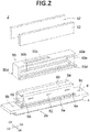
- FIGS. 2 to 8A and 8B a liquid ejection head 2 according to the first embodiment will be explained by using FIGS. 2 to 8A and 8B .
- the channels etc. which are located under the other members and should be drawn by broken lines are drawn by solid lines.
- the liquid ejection head 2 is provided with a head body 2a, housing 50, heat dissipation plates 52, circuit board 54, pressing member 56, elastic members 58, signal transmission members 60, and driver IC 62.
- the liquid ejection head 2 may be provided with just the head body 2a and does not always have to be provided with the housing 50, heat dissipation plates 52, circuit board 54, pressing member 56, elastic members 58, signal transmission members 60, and driver IC 62.
- the signal transmission members 60 are led out from the head body 2a, and the signal transmission members 60 are electrically connected to the circuit board 54.
- the signal transmission members 60 are provided with the driver IC 62 which controls driving of the liquid ejection head 2.
- the driver IC 62 is pressed against the heat dissipation plates 52 by the pressing member 56 through the elastic members 58. Note that, illustration of a support member supporting the circuit board 54 is omitted.
- the heat dissipation plates 52 can be formed by a metal or alloy and are provided for dissipating heat of the driver IC 62 to the outside.
- the heat dissipation plates 52 are joined to the housing 50 by screws or an adhesive.
- the housing 50 is placed on the head body 2a.
- the members configuring the liquid ejection head 2 are covered by the housing 50 and heat dissipation plates 52.
- the housing 50 is provided with openings 50a, 50b, and 50c and heat insulation parts 50d.
- the openings 50a are provided so as to face the third direction D3 and the sixth direction D6, while the heat dissipation plates 52 are arranged so as to close the openings 50a.
- the opening 50b is opened downward.
- the circuit board 54 and pressing member 56 are arranged inside the housing 50 through the opening 50b.
- the opening 50c is opened upward and accommodates a connector (not shown) provided on the circuit board 54.
- the heat insulation parts 50d are provided so as to extend from the second direction D2 to the fifth direction D5. Each is arranged between the heat dissipation plate 52 and the head body 2a. By that, the heat dissipated to the heat dissipation plates 52 becomes hard to be transferred to the head body 2a.
- the housing 50 can be formed by a metal, alloy, or resin.
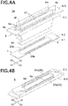
- the head body 2a is shaped long from the second direction D2 toward the fifth direction D5 and has a first channel member 4, second channel member 6, and piezoelectric actuator substrate 40.
- the piezoelectric actuator substrate 40 and second channel member 6 are provided on the first channel member 4.
- the piezoelectric actuator substrate 40 is placed in a region E as indicated by a broken line in FIG. 4A .
- the piezoelectric actuator substrate 40 is provided so as to pressurize a plurality of pressurizing chambers 10 (see FIG. 7B ) provided in the first channel member 4 and has a plurality of displacement members 48 (see FIG. 7B ).
- the piezoelectric actuator substrate 40 having the displacement elements 48 for pressurizing the pressurizing chambers 10 is the pressurizing member.
- the pressurizing member will be explained below by using the piezoelectric actuator substrate.
- the first channel member 4 has channels inside it and guides the liquid supplied from the second channel member 6 to the ejection ports 8 (see FIG. 7B ).
- the first channel member 4 has a first surface 4-1 and second surface 4-2.
- the ejection ports 8 are formed in the first surface 4-1. Further, in the second surface 4-2, openings 20a and 24a are formed.
- the openings 20a are arranged along a line from the second direction D2 to the fifth direction D5 and are arranged in the end part on the third direction D3 side in the second surface 4-2.
- the openings 24a are arranged along a line from the second direction D2 to the fifth direction D5 and are arranged in the end part on the sixth direction D6 side in the second surface 4-2.
- the second channel member 6 has channels formed inside it and guides the liquid supplied from the liquid tank provided at the outside to the first channel member 4.
- the second channel member 6 has a third surface 6-3 and fourth surface 6-4.
- the third surface 6-3 of the second channel member 6 is placed on the second surface 4-2 of the first channel member 4.
- the second channel member 6 is joined through an adhesive (not shown) with the first channel member 4 at the outside of the mounting region E for the piezoelectric actuator substrate 40 which is indicated by a broken line. Due to this, the first channel member 4 and the second channel member 6 are communicated.
- the second channel member 6 has a plurality of first through holes 6a, through holes 6b and 6c, first opening 6d, openings 22a and 26a, and raised part 6e.
- the raised part 6e has a connection part 6f connecting the adjoining first through holes 6a.
- the first through holes 6a are provided on the raised part 6e so as to extend from the second direction D2 to the fifth direction D5 and are arranged on the outer side from the mounting region E for the piezoelectric actuator substrate 40.
- the signal transmission members 60 are inserted through the first through holes 6a.
- the through hole 6b is arranged in the end part on the second direction D2 side in the second channel member 6 and supplies the liquid from the liquid tank to the second channel member 6.
- the through hole 6c is arranged in the end part on the fifth direction D5 side in the second channel member 6 and collects the liquid from the second channel member 6 to the liquid tank.
- the first opening 6d is provided in the third surface 6-3 of the second channel member 6.
- the piezoelectric actuator substrate 40 is accommodated in a space formed by the first opening 6d and the first channel member 4.
- the opening 22a is provided in the third surface 6-3 of the second channel member 6 and is provided so as to extend from the second direction D2 toward the fifth direction D5.
- the opening 22a is formed in the end part on the third direction D3 side in the second channel member 6 and is provided nearer the third direction D3 side from the first through hole 6a.
- the opening 22a is communicated with the through hole 6b, and the first combined channel 22 is formed by sealing the opening 22a by the first channel member 4.
- the opening 26a is provided in the third surface 6-3 of the second channel member 6 and is provided so as to extend from the second direction D2 toward the fifth direction D5.
- the opening 26a is formed in the end part on the sixth direction D6 side in the second channel member 6 and is provided nearer the sixth direction D6 side from the first through hole 6a.
- the opening 26a is communicated with the through hole 6c, and the second combined channel 26 is formed by sealing the opening 26a of the first channel member 4.
- the first combined channel 22 is formed so as to extend from the second direction D2 to the fifth direction D5 and supplies the liquid to the openings 20a of the first channel member 4.
- the second combined channel 26 is formed so as to extend from the second direction D2 to the fifth direction D5 and collects the liquid from the openings 24a of the first channel member 4.
- the raised part 6e protrudes upward from the fourth surface 6-4 and is arranged higher than the fourth surface 6-4.
- the first through holes 6a are formed in the raised part 6e.
- the height of the surface for forming the first through holes 6a therein becomes higher than the fourth surface 6-4 for forming the through holes 6b and 6c therein. Due to this, even in a case where the liquid leaks from the through holes 6b and 6c to the top of the fourth surface 6-4, since the first through holes 6a are provided in the raised part 6e, the leaked liquid becomes hard to flow to the inside through the first through holes 6a.
- the raised part 6e can be given a height of 1 to 5 mm. By the height being 1 mm or more, the liquid becomes harder to flow in from the first through holes 6a.
- connection part 6f is provided so as to connect the adjoining first through holes 6a and is formed so as to extend from the second direction D2 to the fifth direction D5.
- connection part 6f the piezoelectric actuator substrate 40 is covered by the connection part 6f, therefore the liquid becomes hard to deposit on the piezoelectric actuator substrate 40 positioned in the first opening 6d.
- connection part 6f connects the first through holes 6a with each other, therefore the rigidity of the second channel member 6 can be raised, and it becomes harder for deformation to occur in the second channel member 6.
- the liquid supplied from the liquid tank to the through hole 6b is supplied to the first combined channel 22 and flows through the openings 20a and 22a into the first common channels 20, thus the liquid is supplied to the first channel member 4. Further, the liquid collected by the second common channels 24 flows through the openings 24a and 26a into the second combined channel 26, and the liquid is collected at the outside through the through hole 6c.
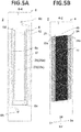
- the first channel member 4 will be explained by using FIGS. 5A and 5B to 7A and 7B .
- the first channel member 4 is formed by stacking a plurality of plates 4a to 4g and has the first surface 4-1 and second surface 4-2.
- the piezoelectric actuator substrate 40 is placed on the second surface 4-2.
- the liquid is ejected from the ejection ports 8 provided in the first surface 4-1.
- the plurality of plates 4a to 4g can be formed by a metal, alloy, or resin. Note that, the first channel member 4 may also be formed integrally by a resin without stacking a plurality of plates 4a to 4g.
- first channel member 4 a plurality of first common channels 20, a plurality of second common channels 24, and a plurality of individual units 15 are formed.
- the openings 20a and 24a are formed in the second surface 4-2.
- the first common channels 20 are provided so as to extend from the first direction D1 to the fourth direction D4 and are formed so as to communicate with the openings 20a. Further, a plurality of first common channels 20 are arranged from the second direction D2 toward the fifth direction D5.
- the second common channels 24 are provided so as to extend from the fourth direction D4 to the first direction D1 and are formed so as to communicate with the openings 24a. Further, the plurality of second common channels 24 are arranged from the second direction D2 toward the fifth direction D5. Each is arranged between each adjoining first common channels 20. For this reason, the first common channels 20 and the second common channels 24 are alternately arranged from the second direction D2 toward the fifth direction D5.
- Ejection units 15 are provided between adjacent first common channels 20 and second common channels 24 and are formed in a matrix in the planar direction of the first channel member 4.
- the angle formed by the first direction D1 and fourth direction D4 and by the second direction D2 and fifth direction D5 becomes larger than a right angle.
- the ejection units 15 which are connected to the same first common channel 20 will be arranged offset to the second direction D2, therefore printing can be carried out so as to fill a predetermined range with pixels formed by the ejected liquid.
- 32 ejection ports 8 are projected in a range of a virtual straight line R.
- the ejection ports 8 are lined up at an interval of 360 dpi within the virtual straight line R. Due to this, if printing while conveying the recording medium P in a direction perpendicular to the virtual straight line R, printing can be carried out with a resolution of 360 dpi.
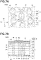
- Each of the ejection units 15, as shown in FIGS. 7A and 7B has an ejection port 8, pressurizing chamber 10, first individual channel 12, and second individual channel 14. Note that, in the liquid injection head 2, the liquid is supplied from the first individual channel 12 to the pressurizing chamber 10. The second individual channel 14 collects the liquid from the pressurizing chamber 10.
- the pressurizing chamber 10 has a pressurizing chamber body 10a and partial channel 10b.
- the pressurizing chamber body 10a forms a circular shape when viewed on a plane.
- the partial channel 10b extends from the center of the pressurizing chamber body 10a toward the lower part.
- the pressurizing chamber body 10a is configured so as to apply pressure to the liquid in the partial channel 10b by pressure received from the displacement element 48 provided on the pressurizing chamber body 10a.
- the pressurizing chamber body 10a has a right circular cylinder shape. Its planar shape is a round shape. By the planar shape being a round shape, the amount of displacement and a change of volume of the pressurizing chamber 10 caused by displacement can be made larger.
- the partial channel 10b has a right circular cylinder shape smaller in diameter than the pressurizing chamber body 10a. Its planar shape is a round shape.
- the partial channel 10b when seen from the second surface 4-2, is arranged at a position contained in the pressurizing chamber body 10a.
- the partial channel 10b connects the pressurizing chamber body 10a and the ejection port 8.
- the partial channel 10b may have a conical shape or truncated cone shape becoming smaller in cross-sectional area toward the ejection port 8 side as well. Due to this, the channel resistances of the first common channel 20 and second common channel 24 can be raised, therefore the difference of pressure loss can be made small.
- the pressurizing chambers 10 are arranged along the two sides of the first common channel 20.
- the first common channel 20 and the pressurizing chambers 10 which are lined up on the two sides thereof are connected through the first individual channels 12.
- the pressurizing chambers 10 are arranged along the two sides of the second common channel 24, and the second common channel 24 and the pressurizing chambers 10 which are lined up on the two sides thereof are connected through the second individual channels 14.
- the first individual channel 12 connects the first common channel 20 and the pressurizing chamber body 10a.
- the first individual channel 12 extends upward from the upper surface of the first common channel 20, then extends toward the second direction D2 or fifth direction D5 and is connected to the lower surface of the pressurizing chamber body 10a.
- the second individual channel 14 connects the second common channel 24 and the partial channel 10b.
- the second individual channel 14 extends from the lower surface of the second common channel 24 toward the second direction D2 or fifth direction D5 and extends toward the first direction D1 or fourth direction D4, then is connected to the side surface of the partial channel 10b.
- the liquid supplied through the openings 20a to the first common channels 20 flows through the first individual channels 12 into the pressurizing chamber bodies 10a and is supplied to the partial channels 10b. Part of the liquid is ejected from the ejection ports 8. Further, the remaining liquid is collected from the partial channels 10b through the second individual channels 14 to the second common channels 24 and are collected through the openings 24a from the first channel member 4 to the second channel member 6.
- the piezoelectric actuator substrate 40 including the displacement elements 48 is joined to the upper surface of the first channel member 4.
- Each displacement element 48 is arranged so as to be positioned at the pressurizing chamber 10.
- the piezoelectric actuator substrate 40 occupies a region having substantially the same shape as that of the pressurizing chamber group formed by the pressurizing chambers 10. Further, the opening of each pressurizing chamber 10 is closed by joining the piezoelectric actuator substrate 40 to the second surface 4-2 of the first channel member 4.
- the piezoelectric actuator substrate 40 has a stacked structure configured by piezoelectric members, that is, two piezoelectric ceramic layers 40a and 40b. Each of these piezoelectric ceramic layers 40a and 40b has a thickness of about 20 ⁇ m. Both piezoelectric ceramic layers 40a and 40b extend across the plurality of pressurizing chambers 10.
- piezoelectric ceramic layers 40a and 40b are for example made of ceramic materials having ferroelectricity such as lead zirconate titanate (PZT)-based, NaNbO 3 -based, BaTiO 3 -based, (BiNa) NbO 3 -based, BiNaNb 5 O 15 -based, or other materials.
- PZT lead zirconate titanate
- NaNbO 3 -based NaNbO 3 -based
- BaTiO 3 -based BaTiO 3 -based
- (BiNa) NbO 3 -based -based
- BiNaNb 5 O 15 -based or other materials.
- the piezoelectric ceramic layer 40b acts as a vibration plate. It does not always have to be a piezoelectric substance.
- Another ceramic layer which is not a piezoelectric substance or a metal plate may be used in place of the former.
- a common electrode 42 On or in the piezoelectric actuator substrate 40, a common electrode 42, individual electrodes 44, and connection electrodes 46 are formed.
- the common electrode 42 is formed over almost the entire surface of the surface direction in a region between the piezoelectric ceramic layer 40a and the piezoelectric ceramic layer 40b. Further, the individual electrodes 44 are arranged at positions facing the pressurizing chambers 10 in the upper surface of the piezoelectric actuator substrate 40.
- the portions in the piezoelectric ceramic layer 40a which are sandwiched between the individual electrodes 44 and the common electrode 42 are polarized in the thickness direction and become the displacement elements 48 of unimorph structures which displace when applying voltage to the individual electrodes 44. For this reason, the piezoelectric actuator substrate 40 has a plurality of displacement elements 48.
- the common electrode 42 can be formed by an Ag-Pd-based or other metal material.
- the thickness of the common electrode 42 can be set to about 2 ⁇ m.
- the common electrode 42 has a common electrode-use surface electrode (not shown) on the piezoelectric ceramic layer 40a.
- the common electrode-use surface electrode is linked through via holes formed penetrating through the piezoelectric ceramic layer 40a with the common electrode 42 and is grounded and held at the ground potential.
- the individual electrodes 44 are formed by Au-based or other metal materials. Each has an individual electrode body 44a and extraction electrode 44b. As shown in FIG. 7A , the individual electrode body 44a, when viewed on a plane, is formed in a substantially circular shape and is formed smaller than the pressurizing chamber body 10a. The extraction electrode 44b is led out from the individual electrode body 44a. The connection electrode 46 is formed on the led out extraction electrode 44b.
- connection electrode 46 is formed by for example silver-palladium containing glass frit, has a thickness of about 15 ⁇ m, and is formed in a convex shape.
- the connection electrode 46 is electrically joined with the electrode (not shown) provided in the signal transmission member 60.
- the displacement elements 48 displace by the driving signals supplied to the individual electrodes 44 through the driver IC 62 etc.
- the driving method use can be made of so-called pull-push driving.
- FIGS. 8A and 8B will be used to explain in detail connection of the first channel member 4 and the second channel member 6. Note that, in FIG. 8B , illustration of the signal transmission member 60 is omitted.
- the first channel member 4 and the second channel member 6 are connected by an epoxy-based adhesive (not shown) by using the second surface 4-2 of the first channel member 4 and the third surface 6-3 of the second channel member 6 as joining surfaces.
- the first combined channels 22 and second combined channels 26 are formed inside. An explanation will be given below by using the first combined channel 22 and second combined channel 26 as the first channels.
- the first combined channel 22 is formed by partition walls 22b and the second surface 4-2 of the first channel member 4.
- the second combined channel 26 is formed by partition walls 26b and the second surface 4-2 of the first channel member 4.
- the fourth surface 6-4 of the second channel member 6 has first partial areas 6-4a, second partial areas 6-4b, and third partial areas 6-4c.
- a first partial area 6-4a is a partial area which is positioned on the first combined channel 22 or second combined channel 26.
- a second partial area 6-4b is a partial area which is positioned on the partition walls 22b of the first combined channel 22 or on the partition walls 26b of the second combined channel 26.
- a third partial area 6-4c is a partial area which is positioned on outer side from the first opening 6d and is other than the first partial areas 6-4a and second partial areas 6-4b.
- the raised part 6e is provided so as to protrude upward from the fourth surface 6-4 of the second channel member 6.
- the raised part 6e when viewed on a plane, is provided at the center of the second direction D2, the fifth direction D5, the third direction D3 and the sixth direction D6 on the fourth surface 6-4 of the second channel member 6.
- the outer circumference 7a of the raised part 6e when viewed on a plane, is positioned on inner side from the outer circumference 7b of the fourth surface 6-4. Further, the outer circumference of the first opening 6d is positioned on inner side from the outer circumference 7a of the raised part 6e.
- connection method of the first channel member 4 and the second channel member 6 will be explained.
- the third surface 6-3 of the second channel member 6 is coated with an adhesive and is positioned with and superimposed on the second surface 4-2 of the first channel member 4.
- the fourth surface 6-4 of the second channel member 6 is pressed to connect the first channel member 4 and the second channel member 6.
- the second channel member 6 is press-fixed while predetermined heat is applied to cure the adhesive and thereby connect the first channel member 4 and the second channel member 6.
- the outer circumference 7a of the raised part 6e is positioned on the inner side from the outer circumference 7b of the fourth surface 6-4.
- the fourth surface 6-4 of the second channel member 6 surrounds the raised part 6e.
- outer circumference 7a of the raised part 6e means the outer edge of the raised part 6e when viewed on a plane
- outer circumference 7b of the fourth surface 6-4 means the outer edge of the fourth surface 6-4 when viewed on a plane.
- the first partial areas 6-4a which are positioned on the first combined channel 22 and second combined channel 26 are formed flush.
- the first partial areas 6-4a positioned on the first combined channel 22 and second combined channel 26 are formed flat. Due to this, the pressing force generated when pressing against the second channel member 6 will be uniformly applied to the first partial areas 6-4a provided on the fourth surface 6-4. As a result, deformation of the second channel member 6 becomes harder to occur in areas positioned between the first partial areas 6-4a and the openings 22a and 26a, therefore deformation becomes harder to occur in the first combined channel 22 and second combined channel 26.
- the cross-sectional areas of the first combined channel 22 and the second combined channel 26 can be made almost constant, the pressure loss up to each ejection unit 15 (see FIG. 7 ) can be made almost constant, therefore variation of ejection characteristics of the ejection units 15 can be reduced.
- the second partial areas 6-4b which are positioned on the partition walls 22b of the first combined channel 22 and on the partition walls 26b of the second combined channel 26 are formed flush.
- the second partial areas 6-4b which are positioned on the partition walls 22b of the first combined channel 22 and on the partition walls 26b of the second combined channel 26 are formed flat. Due to this, the joining surfaces of the first channel member 4 and the second channel member 6 which correspond to the second partial areas 6-4b can be pressed with a uniform pressing force, therefore the seal between the first channel member 4 and the second channel member 6 can be improved.
- the first opening 6d is formed in the fourth surface 6-4
- the piezoelectric actuator substrate 40 is accommodated in a space formed by the first opening 6d and the first channel member 4, and the fourth surface 6-4 is formed flush in the part positioned on the outer side from the first opening 6d.
- the fourth surface 6-4 in the part positioned on outer side from the first opening 6d is formed flat. Due to this, a uniform pressing force can be given to the joining surfaces of the first channel member 4 and the second channel member 6, therefore the space formed by the first opening 6d and the first channel member 4 can be sealed. As a result, when the piezoelectric actuator substrate 40 is arranged in the space, the piezoelectric actuator substrate 40 can be sealed, and the possibility of occurrence of breakage in the liquid ejection head 2 can be reduced.
- flush formation of the fourth surface 6-4, first partial areas 6-4a, second partial areas 6-4b, and third partial areas 6-4c indicate flat formation of the fourth surface 6-4, first partial areas 6-4a, second partial areas 6-4b, and third partial areas 6-4c and indicates that the flatness is 0.3 or less.
- the second channel member 6 has the connection part 6f connecting the first through holes 6a which are adjacent to each other. For this reason, the rigidity which was made low due to the provision of the first through holes 6a can be raised by the connection part 6f, and deformation becomes harder to occur in the second channel member 6. Therefore, the evenness of the fourth surface 6-4 of the second channel member 6 can be held, and the seal between the first channel member 4 and the second channel member 6 can be improved.
- connection part 6f above the piezoelectric actuator substrate 40, the piezoelectric actuator substrate 40 is covered by the connection part 6f. Therefore, even if ink or ink mist intrudes from the upper part of the second channel member 6, leakage of it onto the piezoelectric actuator substrate 40 becomes harder.
- the signal transmission members 60 are led out to the upper part in a state contacting the raised part 6e configuring the first through holes 6a. For this reason, the signal transmission members 60 are guided by the raised part 6e to be led out to the upper part. As a result, it becomes easier to lead out the signal transmission members 60 to the upper part, therefore the productivity of liquid ejection head 2 can be improved.
- liquid ejection head 2 had a plurality of first through holes 6a was shown, but the present disclosure is not limited to this.
- the liquid ejection head 2 may have just one first through hole 6a as well.
- a liquid ejection head 102 according to a second embodiment will be explained by using FIGS. 9A and 9B . Note that, the same notations are attached to the same members.
- the liquid ejection head 102 is provided with a first channel member 4, piezoelectric actuator substrate 40, second channel member 106, housing 150, heat dissipation plates 152, and elastic members 9.
- the second channel member 106 has a third surface 106-3, fourth surface 106-4, first through holes 106a, and raised part 106e.
- the connection member 106f is provided with a first opening 106d opening on the third surface 106-3 side and a second opening 106g opening on the third surface 106-3 side.
- the second opening 106g is provided communicating with the first opening 106d.
- connection part 106f is provided with the second opening 106g opening on the third surface 106-3 side. Due to this, the rigidity of the second channel member 106 is secured, while the weight of the second channel member 106 can be lightened. In particular, this is useful in a case where the liquid ejection head 102 is used in a serial printer.
- the width of the partition wall 106h of the connection part 106f which is between the first through hole 106a and the second opening 106g, is equal to the width of the partition wall 22b of the first combined channel 22 and the width of the partition wall 26b of the second combined channel 26.
- the speed for filling resin into the partition walls 106f of the connection part 106f between the first through holes 106a and the second opening 106g and into the partition walls 22b of the first combined channel 22 and the partition walls 26b of the second combined channel 26 can be made close to uniform.
- connection part 106f partition walls 22b of the first combined channel 22, and partition walls 26b of the second combined channel 26, therefore a second channel member 106 resistant to deformation can be supplied.
- equal thickness of the partition walls 106f, 22b, and 26b includes manufacturing error and is a concept including a range of ⁇ 15%.
- the housing 150 is provided on the second channel member 106 and is placed on the fourth surface 106-4 which is positioned on the outer side from the raised part 106e. For this reason, compared with a case where the housing 150 is placed on the fourth surface 106-4 and on the raised part 106e, the height of the liquid ejection head 102 can be made lower, therefore the liquid ejection head 102 can be made smaller in size.
- the housing 150 is stably placed. As a result, concentration of stress to the joined portions of the housing 150 and the second channel member 106 becomes harder, therefore the reliability of the liquid ejection head 102 can be improved.
- the elastic member 9 is provided adjacent to the outer circumference 107a of the raised part 106e. It is provided so as to surround the outer circumference 107a in a state contacting the outer circumference 107a of the raised part 106e. For this reason, when joining the housing 150 to the second channel member 106, even if the heat insulation portions 150d are pressed by the second channel member 106, due to elastic deformation of the elastic member 9, the possibility of breakage in the heat insulation portions 150d can be reduced.
- the elastic member 9 being provided so as to contact the outer circumference 107a of the raised part 106, the seal between the raised part 106e and the housing 150 can be improved.
- the elastic members 9 can be formed by for example a resin material.
- the elastic member 9 is in contact with the raised part 106e and the fourth surface 106-4 of the second channel member 106. Therefore, even if the housing 150 is pressed by the raised part 106e and fourth surface 106-4, the possibility of breakage in the housing 150 can be reduced.
- the housing 150 when bonding the housing 150 to the second channel member 106 or bonding the heat dissipation plates 152 to the housing 150, there is possibility that the housing 150 will be pressed toward the raised part 106e side or the fourth surface 106-4.
- the elastic member 9 is in contact with the raised part 106e and with the fourth surface 106-4 of the second channel member 106, therefore breakage hardly occurs in the housing 150.
- the elastic member 9 is also provided between the housing 150 and the heat dissipation plates 152. Due to this, even if the heat dissipation plates 152 are pressed by the raised part 106e, the possibility of breakage can be reduced and the seal of the opening 50a of the housing 150 (see FIG. 2 ) can be raised.
- the elastic members 9 may be formed by coating and curing an epoxy-based resin. Use may also be made of O-rings made of resin or metal.
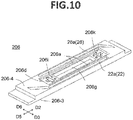
- a liquid ejection head 202 according to a third embodiment will be explained by using FIGS. 10 and 11A and 11B .
- a second channel member 206 has a third surface 206-3, fourth surface 206-4, first through holes 206a, raised part 206e, and connection part 206f.
- connection part 206f is provided with a first opening 206d opening on the third surface 206-3 side, a second opening 206g opening on the third surface 206-3 side, third openings 206k, and second through holes 206i.
- the second opening 206g is provided in communication with the first opening 206d.
- the third openings 206k are provided so as to communicate with the first opening 206d and are provided away from the second opening 206g.
- Each of the third openings 206k when viewed on a plane, is provided outside the second opening 206g on the second direction D2 side or on the fifth direction D5 side.
- connection part 207f when viewed on a plane, the third openings 206k are provided on the outside of the second opening 206g. In other words, each of the third openings 206k is provided outside the second opening 206g on the second direction D2 side or on the fifth direction D5 side. Due to this, when preparing the second channel member 206 by injection molding, even if resin is filled from the fifth direction D5 toward the second direction D2, flow of a large amount of resin to the connection part 207f becomes harder. Due to this, shortage of resin becomes harder to occur in the partition walls 206h formed by the first through holes 206a and second opening 206g, in the partition walls 22b of the first combined channel 22, and in the partition walls 26b of the second combined channel 26.
- the resin flowing from the fifth direction D5 toward the second direction D2 flows easier to the connection part 206f having a large cross-sectional area.
- the cross-sectional area of the partition wall 206h of the connection part 206f can be a made close to the cross-sectional area of each of the partition walls 22b and 26b, therefore the speed of filling resin in the vicinity of the third openings 206k can be made approximately uniform.
- the third openings 206k when viewed on a plane, need not be individually provided outside the second opening 206g on the second direction D2 side and on the fifth direction D5 side either. They only have to be provided on the upstream side of the direction for filling resin from the second opening 206g.
- a concave portion 206j is provided at the position opposite to the second opening 206g among walls configuring the third opening 206k. Due to this, when filling resin from the fifth direction D5 toward the second direction D2, resin flows more easily to the connection part 207f compared with the partition walls 22b and 22d, and shortage of resin becomes harder to occur in the connection part 207f. That is, the amount of the resin flowing into the partition walls 22b and 26b is secured, while a sufficient amount of resin can flow into the connection part 207f.
- the second through holes 206i are provided so as to communicate with the first opening 206d and are provided away from the second opening 206g and third openings 206k.
- the second through holes 206i are provided between the second opening 206g and the third openings 206k.
- the second through hole 206i has a first partial area 206i1 and second partial area 206i2.
- the first partial area 206i1 is provided from the raised part 206e of the second channel member 206 toward the inside.
- the second partial area 206i2 is provided from the first opening 206d of the second channel member 206 toward the internal portion.
- the first partial area 206i1 and the second partial area 206i2 are provided so as to communicate with each other.
- the first partial area 206i1 exhibits a circular shape when viewed on a plane.
- the second partial area 206i2 exhibits a rectangular shape when viewed on a plane.
- the second partial area 206i2 has apexes at which the sides cross when viewed on a plane. The apexes are positioned so as to face the second direction D2.
- the diagonal line of the second partial area 206i2 is formed longer than the diameter of the first partial area 206i1. For this reason, when viewed on a plane, the second partial area 206i2 is formed larger than the first partial area 206i1.
- a fastening member 28 is accommodated in the second partial area 206i2.
- the fastening member 28 for example use can be made of a nut etc.
- a screw inserted from the raised part 206e side is screwed in the fastening member 28 and fixed. Due to this, the member provided on the second channel member 206 can be fastened to the second channel member 206
- the apexes of the second partial area 206i2 are positioned so as to face the second direction D2. For this reason, where the second channel member 206 is prepared by injection molding, it becomes harder to prevent the flow of the supplied resin by the second through hole 206i. That is, the supplied resin strikes the apexes, then flows along the side of the second partial area 206i2 to the partition wall 206h between the first through hole 206a and the second opening 206g. As a result, the resin can be smoothly supplied to the partition wall 206h between the first through hole 206a and the second opening 206g. Therefore, shortage of the resin which is supplied to the partition wall 206h becomes harder to occur.
- the second partial area 206i2 only have to be a polygonal shape when viewed on a plane and is not limited to a rectangular shape. For example, it may be a hexagonal shape. Further, the second through hole 206i need not have the first partial area 206i1 and second partial area 206i2 and may be a polygonal prism shape.
- the actuator substrate 40 was illustrated as a pressurizing member, but it is not limited to this.
- a pressurizing member providing a heat generating portion for each pressurizing chamber 10, heating the liquid inside the pressurizing chamber 10 by the heat of the heat generating portion, and performing pressurization by thermal expansion of the liquid may be employed as well.
- liquid ejection head 2 a configuration supplying the liquid from the through hole 6b of the second channel member 6 and collecting the liquid which was not ejected from the through hole 6c was shown, but the configuration is not limited to this.
- a configuration supplying liquid from the through hole 6c of the second channel member 6 and collecting the liquid which is not ejected from the through hole 6b may be employed as well.
Description
- The present invention relates to a liquid ejection head according to
claim 1 and a recording device. - A liquid ejection head of the initially mentioned type is, e.g., known from
JP 2014 046627 A - Conventionally, as a printing head, there has been known a liquid ejection head performing various types of printing by ejecting a liquid onto a recording medium. As such a liquid ejection head, there is known a head provided with a first channel member having a first surface, a plurality of ejection ports which are provided in the first surface, a plurality of pressurizing chambers which are individually communicated with the plurality of ejection ports, and a second surface which is positioned on the opposite side to the first surface; with a pressurizing member which is provided on the second surface; and with a second channel member having a third surface, a fourth surface which is positioned on the opposite side to the third surface, a raised part which protrudes from the fourth surface, and a first through hole which is provided in the raised part. Due to this, inflow of the liquid supplied to the second channel member through the first through hole to the inside is suppressed (see for example Patent Literature 1).
- Patent Literature 1: Japanese Patent Publication No.
2014-162192A - The invention provides a liquid ejection head according to
claim 1 and a recording device according toclaim 15. Further embodiments are described in the dependent claims. -
-
FIG. 1A is a side view schematically showing a recording device including a liquid ejection head according to a first embodiment, andFIG. 1B is a plan view schematically showing the recording device shown inFIG. 1A . -
FIG. 2 is a disassembled perspective view of the liquid ejection head according to the first embodiment. -
FIG. 3A is a perspective view of the liquid ejection head inFIG. 2 , andFIG. 3B is a cross-sectional view taken along the IIIb-IIIb line inFIG. 3A . -
FIG. 4A is a disassembled perspective view of a head body, andFIG. 4B is a perspective view of a second channel member seen from the third surface side. -
FIG. 5A is a plan view of the second channel member and actuator substrate, andFIG. 5B is a bottom view of the first channel member and actuator substrate. -
FIG. 6 is a plan view showing a portion inFIG. 5 enlarged. -
FIG. 7A is a plan view showing a portion inFIG. 6 enlarged, andFIG. 7B is a cross-sectional view taken along the VIIb-VIIb line inFIG. 7A . -
FIG. 8A is a plan view of the second channel member, andFIG. 8B is a cross-sectional view of the liquid ejection head enlarged. -
FIGS. 9A and 9B show a liquid ejection head according to a second embodiment, in whichFIG. 9A is a perspective view of the second channel member seen from the third surface side, andFIG. 9B is a cross-sectional view showing a portion in the liquid ejection head according to the second embodiment enlarged. -
FIG. 10 shows a liquid ejection head according to a third embodiment and is a perspective view of the second channel member seen from the third surface side. -
FIG. 11A is a plan view showing a portion in the liquid ejection head according to the third embodiment enlarged, andFIG. 11B is a cross-sectional view taken along the XIb-XIb line inFIG. 11A . - A color inkjet printer 1 (below, referred to as a "
printer 1") including aliquid ejection head 2 according to a first embodiment will be explained by usingFIGS. 1A and 1B . The drawings show a first direction D1, second direction D2, third direction D3, fourth direction D4, fifth direction D5, and sixth direction D6. The first direction D1 is one side of the direction in which a firstcommon channel 20 and secondcommon channel 24 extend, while the fourth direction D4 is the other side of the direction in which the firstcommon channel 20 and secondcommon channel 24 extend. The second direction D2 is one side of the direction in which a first combinedchannel 22 and second combinedchannel 26 extend, and the fifth direction D5 is the other side of the direction in which the first combinedchannel 22 and second combinedchannel 26 extend. The third direction D3 is one side of the direction perpendicular to the direction in which the first combinedchannel 22 and second combinedchannel 26 extend, and the sixth direction D6 is the other side of the direction perpendicular to the direction in which the first combinedchannel 22 and second combinedchannel 26 extend. - The
printer 1 conveys a recording medium P from aconveying roller 74a to a conveyingroller 74b to thereby make a recording medium P relatively move with respect to theliquid ejection heads 2. Thecontrol part 76 controls theliquid ejection heads 2 based on image and text data to make them eject liquid toward the recording medium P to deposit droplets on the recording medium P and thereby print the recording medium P. - In the present embodiment, the
liquid ejection heads 2 are fixed with respect to theprinter 1, and theprinter 1 becomes so-called line printer. As another embodiment of the recording device, so-called serial printer can be mentioned. - In the
printer 1, a flat-shapedhead mount frame 70 is fastened so as to become substantially parallel to the recording medium P. Thehead mount frame 70 is provided with 20 holes (not shown). Twentyliquid ejection heads 2 are mounted in the holes. Fiveliquid ejection heads 2 configure onehead group 72, so theprinter 1 has fourhead groups 72. - The
liquid ejection head 2 forms an elongated long shape from the second direction D2 to the fifth direction D5. In onehead group 72, threeliquid ejection heads 2 are arranged along a line from the second direction D2 to the fifth direction D5, while the other twoliquid ejection heads 2 are arranged at positions which are offset to the fifth direction D5. The adjoiningliquid ejection heads 2 are arranged so that ranges which can be printed by theliquid ejection heads 2 are connected from the second direction D2 to the fifth direction D5 or overlap at the ends, therefore printing without gaps becomes possible in the width direction of the recording medium P. - The four
head groups 72 are arranged from the third direction D3 to the sixth direction D6. Eachliquid ejection head 2 is supplied with ink from a not shown liquid tank. The liquid ejection heads 2 belonging to onehead group 72 are supplied with ink of the same color. Four colors of ink are printed by the four head groups. The colors of inks ejected from thehead groups 72 are for example magenta (M), yellow (Y), cyan (C), and black (K). - Note that, the number of the liquid ejection heads 2 mounted in the
printer 1 may be one as well so far as printing is carried out in a range which can be printed by oneliquid ejection head 2 in a single color. The number of liquid ejection heads 2 included in thehead group 72 or the number ofhead groups 72 can be suitably changed according to the target of printing or the printing conditions. For example, the number ofhead groups 72 may be increased as well in order to perform printing by still further colors. Further, by arranging a plurality ofhead groups 72 for printing in the same color and alternately printing in the conveying direction, the printing speed, that is, the conveying speed, can be raised. Further, the resolution in the width direction of the recording medium P may be raised by preparing a plurality ofhead groups 2 for printing in the same color and arranging them offset to the third direction D3 as well. - Further, other than printing colored inks, a coating agent or other liquid may be printed as well for surface treatment of the recording medium P.
- The
printer 1 performs printing on the recording medium P. The recording medium P has been wound around the conveyingroller 74a. It passes between two conveyingrollers 74c, then passes under the liquid ejection heads 2 mounted in thehead mount frame 70. After that, it passes between the two conveyingrollers 74d and is finally collected by the conveyingroller 74b. - The recording medium P may be fabric or the like other than printing paper. Further, the
printer 1 may be made a form conveying a conveying belt in place of the recording medium P, while the recording medium P may be a sheet of paper, cut fabric, wood, tile, etc. placed on the conveying belt besides a roll-shaped medium. Further, liquid containing conductive particles may be ejected from the liquid ejection heads 2 to print a wiring pattern of an electronic apparatus etc. as well. Further, predetermined amounts of liquid chemical agents or liquids containing chemical agents may be ejected from the liquid ejection heads 2 toward a reaction vessel or the like to cause a reaction and thereby prepare pharmaceutical products. - Further, a position sensor, speed sensor, temperature sensor, or the like may be attached to the
printer 1, and thecontrol part 76 may control portions in theprinter 1 in accordance with the states of the portions in theprinter 1 seen from the information of the sensors. In particular, when the ejection amount, ejection speed, and other ejection characteristics of the liquid ejected from aliquid ejection head 2 are influenced by the outside, a driving signal for making theliquid ejection head 2 eject liquid may be changed in accordance with the temperature of theliquid ejection head 2, temperature of the liquid in the liquid tank, or the pressure which is being applied to theliquid ejection head 2 by the liquid in the liquid tank. - Next, a
liquid ejection head 2 according to the first embodiment will be explained by usingFIGS. 2 to 8A and8B . Note that, for easier understanding of the drawings, in FIGS. 5A and 5B to 7A and 7B , the channels etc. which are located under the other members and should be drawn by broken lines are drawn by solid lines. - As shown in
FIGS. 2 and3A and 3B , theliquid ejection head 2 is provided with ahead body 2a,housing 50,heat dissipation plates 52,circuit board 54, pressingmember 56,elastic members 58,signal transmission members 60, anddriver IC 62. Note that, theliquid ejection head 2 may be provided with just thehead body 2a and does not always have to be provided with thehousing 50,heat dissipation plates 52,circuit board 54, pressingmember 56,elastic members 58,signal transmission members 60, anddriver IC 62. - In the
liquid ejection head 2, thesignal transmission members 60 are led out from thehead body 2a, and thesignal transmission members 60 are electrically connected to thecircuit board 54. Thesignal transmission members 60 are provided with thedriver IC 62 which controls driving of theliquid ejection head 2. Thedriver IC 62 is pressed against theheat dissipation plates 52 by the pressingmember 56 through theelastic members 58. Note that, illustration of a support member supporting thecircuit board 54 is omitted. - The
heat dissipation plates 52 can be formed by a metal or alloy and are provided for dissipating heat of thedriver IC 62 to the outside. Theheat dissipation plates 52 are joined to thehousing 50 by screws or an adhesive. - The
housing 50 is placed on thehead body 2a. The members configuring theliquid ejection head 2 are covered by thehousing 50 andheat dissipation plates 52. Thehousing 50 is provided withopenings heat insulation parts 50d. - The
openings 50a are provided so as to face the third direction D3 and the sixth direction D6, while theheat dissipation plates 52 are arranged so as to close theopenings 50a. Theopening 50b is opened downward. Thecircuit board 54 and pressingmember 56 are arranged inside thehousing 50 through theopening 50b. Theopening 50c is opened upward and accommodates a connector (not shown) provided on thecircuit board 54. - The
heat insulation parts 50d are provided so as to extend from the second direction D2 to the fifth direction D5. Each is arranged between theheat dissipation plate 52 and thehead body 2a. By that, the heat dissipated to theheat dissipation plates 52 becomes hard to be transferred to thehead body 2a. Thehousing 50 can be formed by a metal, alloy, or resin. - As shown in
FIG. 4A , thehead body 2a is shaped long from the second direction D2 toward the fifth direction D5 and has afirst channel member 4,second channel member 6, andpiezoelectric actuator substrate 40. Thepiezoelectric actuator substrate 40 andsecond channel member 6 are provided on thefirst channel member 4. Thepiezoelectric actuator substrate 40 is placed in a region E as indicated by a broken line inFIG. 4A . Thepiezoelectric actuator substrate 40 is provided so as to pressurize a plurality of pressurizing chambers 10 (seeFIG. 7B ) provided in thefirst channel member 4 and has a plurality of displacement members 48 (seeFIG. 7B ). Note that, thepiezoelectric actuator substrate 40 having thedisplacement elements 48 for pressurizing the pressurizingchambers 10 is the pressurizing member. The pressurizing member will be explained below by using the piezoelectric actuator substrate. - The
first channel member 4 has channels inside it and guides the liquid supplied from thesecond channel member 6 to the ejection ports 8 (seeFIG. 7B ). Thefirst channel member 4 has a first surface 4-1 and second surface 4-2. Theejection ports 8 are formed in the first surface 4-1. Further, in the second surface 4-2,openings - The
openings 20a are arranged along a line from the second direction D2 to the fifth direction D5 and are arranged in the end part on the third direction D3 side in the second surface 4-2. Theopenings 24a are arranged along a line from the second direction D2 to the fifth direction D5 and are arranged in the end part on the sixth direction D6 side in the second surface 4-2. - The
second channel member 6 has channels formed inside it and guides the liquid supplied from the liquid tank provided at the outside to thefirst channel member 4. Thesecond channel member 6 has a third surface 6-3 and fourth surface 6-4. The third surface 6-3 of thesecond channel member 6 is placed on the second surface 4-2 of thefirst channel member 4. - The
second channel member 6 is joined through an adhesive (not shown) with thefirst channel member 4 at the outside of the mounting region E for thepiezoelectric actuator substrate 40 which is indicated by a broken line. Due to this, thefirst channel member 4 and thesecond channel member 6 are communicated. - As shown in
FIGS. 4A and 4B and5A and 5B , thesecond channel member 6 has a plurality of first throughholes 6a, throughholes first opening 6d,openings part 6e. The raisedpart 6e has aconnection part 6f connecting the adjoining first throughholes 6a. The first throughholes 6a are provided on the raisedpart 6e so as to extend from the second direction D2 to the fifth direction D5 and are arranged on the outer side from the mounting region E for thepiezoelectric actuator substrate 40. Thesignal transmission members 60 are inserted through the first throughholes 6a. - The through
hole 6b is arranged in the end part on the second direction D2 side in thesecond channel member 6 and supplies the liquid from the liquid tank to thesecond channel member 6. The throughhole 6c is arranged in the end part on the fifth direction D5 side in thesecond channel member 6 and collects the liquid from thesecond channel member 6 to the liquid tank. Thefirst opening 6d is provided in the third surface 6-3 of thesecond channel member 6. Thepiezoelectric actuator substrate 40 is accommodated in a space formed by thefirst opening 6d and thefirst channel member 4. - The
opening 22a is provided in the third surface 6-3 of thesecond channel member 6 and is provided so as to extend from the second direction D2 toward the fifth direction D5. Theopening 22a is formed in the end part on the third direction D3 side in thesecond channel member 6 and is provided nearer the third direction D3 side from the first throughhole 6a. Theopening 22a is communicated with the throughhole 6b, and the first combinedchannel 22 is formed by sealing theopening 22a by thefirst channel member 4. - The
opening 26a is provided in the third surface 6-3 of thesecond channel member 6 and is provided so as to extend from the second direction D2 toward the fifth direction D5. Theopening 26a is formed in the end part on the sixth direction D6 side in thesecond channel member 6 and is provided nearer the sixth direction D6 side from the first throughhole 6a. Theopening 26a is communicated with the throughhole 6c, and the second combinedchannel 26 is formed by sealing theopening 26a of thefirst channel member 4. - The first combined
channel 22 is formed so as to extend from the second direction D2 to the fifth direction D5 and supplies the liquid to theopenings 20a of thefirst channel member 4. The second combinedchannel 26 is formed so as to extend from the second direction D2 to the fifth direction D5 and collects the liquid from theopenings 24a of thefirst channel member 4. - The raised
part 6e protrudes upward from the fourth surface 6-4 and is arranged higher than the fourth surface 6-4. The first throughholes 6a are formed in the raisedpart 6e. The height of the surface for forming the first throughholes 6a therein becomes higher than the fourth surface 6-4 for forming the throughholes holes holes 6a are provided in the raisedpart 6e, the leaked liquid becomes hard to flow to the inside through the first throughholes 6a. The raisedpart 6e can be given a height of 1 to 5 mm. By the height being 1 mm or more, the liquid becomes harder to flow in from the first throughholes 6a. - The
connection part 6f is provided so as to connect the adjoining first throughholes 6a and is formed so as to extend from the second direction D2 to the fifth direction D5. By provision of theconnection part 6f, thepiezoelectric actuator substrate 40 is covered by theconnection part 6f, therefore the liquid becomes hard to deposit on thepiezoelectric actuator substrate 40 positioned in thefirst opening 6d. - Further, the
connection part 6f connects the first throughholes 6a with each other, therefore the rigidity of thesecond channel member 6 can be raised, and it becomes harder for deformation to occur in thesecond channel member 6. - By the above configuration, in the
second channel member 6, the liquid supplied from the liquid tank to the throughhole 6b is supplied to the first combinedchannel 22 and flows through theopenings common channels 20, thus the liquid is supplied to thefirst channel member 4. Further, the liquid collected by the secondcommon channels 24 flows through theopenings channel 26, and the liquid is collected at the outside through the throughhole 6c. - The
first channel member 4 will be explained by usingFIGS. 5A and 5B to 7A and 7B . - The
first channel member 4 is formed by stacking a plurality ofplates 4a to 4g and has the first surface 4-1 and second surface 4-2. Thepiezoelectric actuator substrate 40 is placed on the second surface 4-2. The liquid is ejected from theejection ports 8 provided in the first surface 4-1. The plurality ofplates 4a to 4g can be formed by a metal, alloy, or resin. Note that, thefirst channel member 4 may also be formed integrally by a resin without stacking a plurality ofplates 4a to 4g. - In the
first channel member 4, a plurality of firstcommon channels 20, a plurality of secondcommon channels 24, and a plurality ofindividual units 15 are formed. Theopenings - The first
common channels 20 are provided so as to extend from the first direction D1 to the fourth direction D4 and are formed so as to communicate with theopenings 20a. Further, a plurality of firstcommon channels 20 are arranged from the second direction D2 toward the fifth direction D5. - The second
common channels 24 are provided so as to extend from the fourth direction D4 to the first direction D1 and are formed so as to communicate with theopenings 24a. Further, the plurality of secondcommon channels 24 are arranged from the second direction D2 toward the fifth direction D5. Each is arranged between each adjoining firstcommon channels 20. For this reason, the firstcommon channels 20 and the secondcommon channels 24 are alternately arranged from the second direction D2 toward the fifth direction D5. -
Ejection units 15 are provided between adjacent firstcommon channels 20 and secondcommon channels 24 and are formed in a matrix in the planar direction of thefirst channel member 4. The angle formed by the first direction D1 and fourth direction D4 and by the second direction D2 and fifth direction D5 becomes larger than a right angle. For this reason, theejection units 15 which are connected to the same firstcommon channel 20 will be arranged offset to the second direction D2, therefore printing can be carried out so as to fill a predetermined range with pixels formed by the ejected liquid. - When projecting the
ejection ports 8 to the third direction D3 and sixth direction D6, 32ejection ports 8 are projected in a range of a virtual straight line R. Theejection ports 8 are lined up at an interval of 360 dpi within the virtual straight line R. Due to this, if printing while conveying the recording medium P in a direction perpendicular to the virtual straight line R, printing can be carried out with a resolution of 360 dpi. - Each of the
ejection units 15, as shown inFIGS. 7A and 7B , has anejection port 8, pressurizingchamber 10, firstindividual channel 12, and secondindividual channel 14. Note that, in theliquid injection head 2, the liquid is supplied from the firstindividual channel 12 to the pressurizingchamber 10. The secondindividual channel 14 collects the liquid from the pressurizingchamber 10. - The pressurizing
chamber 10 has a pressurizingchamber body 10a andpartial channel 10b. The pressurizingchamber body 10a forms a circular shape when viewed on a plane. Thepartial channel 10b extends from the center of the pressurizingchamber body 10a toward the lower part. The pressurizingchamber body 10a is configured so as to apply pressure to the liquid in thepartial channel 10b by pressure received from thedisplacement element 48 provided on the pressurizingchamber body 10a. - The pressurizing
chamber body 10a has a right circular cylinder shape. Its planar shape is a round shape. By the planar shape being a round shape, the amount of displacement and a change of volume of the pressurizingchamber 10 caused by displacement can be made larger. - The
partial channel 10b has a right circular cylinder shape smaller in diameter than the pressurizingchamber body 10a. Its planar shape is a round shape. Thepartial channel 10b, when seen from the second surface 4-2, is arranged at a position contained in the pressurizingchamber body 10a. Thepartial channel 10b connects the pressurizingchamber body 10a and theejection port 8. - Note that, the
partial channel 10b may have a conical shape or truncated cone shape becoming smaller in cross-sectional area toward theejection port 8 side as well. Due to this, the channel resistances of the firstcommon channel 20 and secondcommon channel 24 can be raised, therefore the difference of pressure loss can be made small. - The pressurizing
chambers 10 are arranged along the two sides of the firstcommon channel 20. The firstcommon channel 20 and the pressurizingchambers 10 which are lined up on the two sides thereof are connected through the firstindividual channels 12. Further, the pressurizingchambers 10 are arranged along the two sides of the secondcommon channel 24, and the secondcommon channel 24 and the pressurizingchambers 10 which are lined up on the two sides thereof are connected through the secondindividual channels 14. - The first
individual channel 12 connects the firstcommon channel 20 and the pressurizingchamber body 10a. The firstindividual channel 12 extends upward from the upper surface of the firstcommon channel 20, then extends toward the second direction D2 or fifth direction D5 and is connected to the lower surface of the pressurizingchamber body 10a. - The second
individual channel 14 connects the secondcommon channel 24 and thepartial channel 10b. The secondindividual channel 14 extends from the lower surface of the secondcommon channel 24 toward the second direction D2 or fifth direction D5 and extends toward the first direction D1 or fourth direction D4, then is connected to the side surface of thepartial channel 10b. - By the configuration as described above, in the
first channel member 4, the liquid supplied through theopenings 20a to the firstcommon channels 20 flows through the firstindividual channels 12 into the pressurizingchamber bodies 10a and is supplied to thepartial channels 10b. Part of the liquid is ejected from theejection ports 8. Further, the remaining liquid is collected from thepartial channels 10b through the secondindividual channels 14 to the secondcommon channels 24 and are collected through theopenings 24a from thefirst channel member 4 to thesecond channel member 6. - The
piezoelectric actuator substrate 40 including thedisplacement elements 48 is joined to the upper surface of thefirst channel member 4. Eachdisplacement element 48 is arranged so as to be positioned at the pressurizingchamber 10. Thepiezoelectric actuator substrate 40 occupies a region having substantially the same shape as that of the pressurizing chamber group formed by the pressurizingchambers 10. Further, the opening of each pressurizingchamber 10 is closed by joining thepiezoelectric actuator substrate 40 to the second surface 4-2 of thefirst channel member 4. - The
piezoelectric actuator substrate 40 has a stacked structure configured by piezoelectric members, that is, two piezoelectricceramic layers ceramic layers ceramic layers chambers 10. - These piezoelectric
ceramic layers ceramic layer 40b acts as a vibration plate. It does not always have to be a piezoelectric substance. Another ceramic layer which is not a piezoelectric substance or a metal plate may be used in place of the former. - On or in the
piezoelectric actuator substrate 40, acommon electrode 42,individual electrodes 44, andconnection electrodes 46 are formed. Thecommon electrode 42 is formed over almost the entire surface of the surface direction in a region between the piezoelectricceramic layer 40a and the piezoelectricceramic layer 40b. Further, theindividual electrodes 44 are arranged at positions facing the pressurizingchambers 10 in the upper surface of thepiezoelectric actuator substrate 40. - The portions in the piezoelectric
ceramic layer 40a which are sandwiched between theindividual electrodes 44 and thecommon electrode 42 are polarized in the thickness direction and become thedisplacement elements 48 of unimorph structures which displace when applying voltage to theindividual electrodes 44. For this reason, thepiezoelectric actuator substrate 40 has a plurality ofdisplacement elements 48. - The
common electrode 42 can be formed by an Ag-Pd-based or other metal material. The thickness of thecommon electrode 42 can be set to about 2 µm. Thecommon electrode 42 has a common electrode-use surface electrode (not shown) on the piezoelectricceramic layer 40a. The common electrode-use surface electrode is linked through via holes formed penetrating through the piezoelectricceramic layer 40a with thecommon electrode 42 and is grounded and held at the ground potential. - The
individual electrodes 44 are formed by Au-based or other metal materials. Each has anindividual electrode body 44a andextraction electrode 44b. As shown inFIG. 7A , theindividual electrode body 44a, when viewed on a plane, is formed in a substantially circular shape and is formed smaller than the pressurizingchamber body 10a. Theextraction electrode 44b is led out from theindividual electrode body 44a. Theconnection electrode 46 is formed on the led outextraction electrode 44b. - The
connection electrode 46 is formed by for example silver-palladium containing glass frit, has a thickness of about 15 µm, and is formed in a convex shape. Theconnection electrode 46 is electrically joined with the electrode (not shown) provided in thesignal transmission member 60. - Next, the ejection operation of liquid will be explained. Under the control from the
control part 76, thedisplacement elements 48 displace by the driving signals supplied to theindividual electrodes 44 through thedriver IC 62 etc. As the driving method, use can be made of so-called pull-push driving. -
FIGS. 8A and 8B will be used to explain in detail connection of thefirst channel member 4 and thesecond channel member 6. Note that, inFIG. 8B , illustration of thesignal transmission member 60 is omitted. - The
first channel member 4 and thesecond channel member 6 are connected by an epoxy-based adhesive (not shown) by using the second surface 4-2 of thefirst channel member 4 and the third surface 6-3 of thesecond channel member 6 as joining surfaces. - In the
second channel member 6, the first combinedchannels 22 and second combinedchannels 26 are formed inside. An explanation will be given below by using the first combinedchannel 22 and second combinedchannel 26 as the first channels. The first combinedchannel 22 is formed bypartition walls 22b and the second surface 4-2 of thefirst channel member 4. The second combinedchannel 26 is formed bypartition walls 26b and the second surface 4-2 of thefirst channel member 4. - The fourth surface 6-4 of the
second channel member 6 has first partial areas 6-4a, second partial areas 6-4b, and third partial areas 6-4c. A first partial area 6-4a is a partial area which is positioned on the first combinedchannel 22 or second combinedchannel 26. A second partial area 6-4b is a partial area which is positioned on thepartition walls 22b of the first combinedchannel 22 or on thepartition walls 26b of the second combinedchannel 26. A third partial area 6-4c is a partial area which is positioned on outer side from thefirst opening 6d and is other than the first partial areas 6-4a and second partial areas 6-4b. - The raised
part 6e is provided so as to protrude upward from the fourth surface 6-4 of thesecond channel member 6. The raisedpart 6e, when viewed on a plane, is provided at the center of the second direction D2, the fifth direction D5, the third direction D3 and the sixth direction D6 on the fourth surface 6-4 of thesecond channel member 6. Theouter circumference 7a of the raisedpart 6e, when viewed on a plane, is positioned on inner side from theouter circumference 7b of the fourth surface 6-4. Further, the outer circumference of thefirst opening 6d is positioned on inner side from theouter circumference 7a of the raisedpart 6e. - The connection method of the
first channel member 4 and thesecond channel member 6 will be explained. First, the third surface 6-3 of thesecond channel member 6 is coated with an adhesive and is positioned with and superimposed on the second surface 4-2 of thefirst channel member 4. Next, using a predetermined jig, the fourth surface 6-4 of thesecond channel member 6 is pressed to connect thefirst channel member 4 and thesecond channel member 6. Next, thesecond channel member 6 is press-fixed while predetermined heat is applied to cure the adhesive and thereby connect thefirst channel member 4 and thesecond channel member 6. - Here, when pressing against the
second channel member 6 from the fourth surface 6-4 side, it is necessary to simultaneously press against both of the fourth surface 6-4 and the upper surface of the raisedpart 6e in order to connect thefirst channel member 4 and thesecond channel member 6 since the raisedpart 6e protrudes from the fourth surface 6-4. However, the fourth surface 6-4 and the raisedpart 6e are different in height, therefore they sometimes cannot be pressed with a uniform force. Due to this, a uniform pressing force is not given to the joining surfaces of thefirst channel member 4 and thesecond channel member 6, therefore the seal of the joining surfaces of thefirst channel member 4 andsecond channel member 6 is liable to degrade. - Contrary to this, in the
liquid ejection head 2, when viewed on a plane, theouter circumference 7a of the raisedpart 6e is positioned on the inner side from theouter circumference 7b of the fourth surface 6-4. For this reason, when viewed on a plane, the fourth surface 6-4 of thesecond channel member 6 surrounds the raisedpart 6e. As a result, by pressing against only the fourth surface 6-4, thefirst channel member 4 and thesecond channel member 6 can be connected, and a uniform pressing force can be given to the joining surfaces of thefirst channel member 4 andsecond channel member 6. Therefore, the seal of thefirst channel member 4 and thesecond channel member 6 can be improved. - That is, by pressing against only the fourth surface 6-4 surrounding the raised
part 6e, a uniform pressing force can be given to the joining surfaces of thefirst channel member 4 andsecond channel member 6, therefore the seal of the joining surfaces of thefirst channel member 4 and thesecond channel member 6 corresponding to the fourth surface 6-4 can be raised. - Note that, the
outer circumference 7a of the raisedpart 6e means the outer edge of the raisedpart 6e when viewed on a plane, while theouter circumference 7b of the fourth surface 6-4 means the outer edge of the fourth surface 6-4 when viewed on a plane. - Further, on the fourth surface 6-4, the first partial areas 6-4a which are positioned on the first combined
channel 22 and second combinedchannel 26 are formed flush. In other words, on the fourth surface 6-4, the first partial areas 6-4a positioned on the first combinedchannel 22 and second combinedchannel 26 are formed flat. Due to this, the pressing force generated when pressing against thesecond channel member 6 will be uniformly applied to the first partial areas 6-4a provided on the fourth surface 6-4. As a result, deformation of thesecond channel member 6 becomes harder to occur in areas positioned between the first partial areas 6-4a and theopenings channel 22 and second combinedchannel 26. - Therefore, the cross-sectional areas of the first combined
channel 22 and the second combinedchannel 26 can be made almost constant, the pressure loss up to each ejection unit 15 (seeFIG. 7 ) can be made almost constant, therefore variation of ejection characteristics of theejection units 15 can be reduced. - Further, in the fourth surface 6-4, the second partial areas 6-4b which are positioned on the
partition walls 22b of the first combinedchannel 22 and on thepartition walls 26b of the second combinedchannel 26 are formed flush. In other words, in the fourth surface 6-4, the second partial areas 6-4b which are positioned on thepartition walls 22b of the first combinedchannel 22 and on thepartition walls 26b of the second combinedchannel 26 are formed flat. Due to this, the joining surfaces of thefirst channel member 4 and thesecond channel member 6 which correspond to the second partial areas 6-4b can be pressed with a uniform pressing force, therefore the seal between thefirst channel member 4 and thesecond channel member 6 can be improved. - That is, with respect to the joining surfaces of the
first channel member 4 and thesecond channel member 6 which become the bonding margin, by directly pressing against the second partial areas 6-4b, a uniform pressing force can be applied to the joining surfaces of thefirst channel member 4 andsecond channel member 6, therefore the seal between thefirst channel member 4 and thesecond channel member 6 can be improved. - In particular, in the case of the
second channel member 6 which is formed long from the second direction D2 toward the fifth direction D5, sometimes warping or bending occurs in thesecond channel member 6 from the second direction D2 to the fifth direction D5. Contrary to this, in theliquid ejection head 2, by the second partial areas 6-4b being formed flush, the second partial areas 6-4b can be strongly pressed, therefore the seal between thefirst channel member 4 and thesecond channel member 6 can be raised. - Further, in the
second channel member 6, thefirst opening 6d is formed in the fourth surface 6-4, thepiezoelectric actuator substrate 40 is accommodated in a space formed by thefirst opening 6d and thefirst channel member 4, and the fourth surface 6-4 is formed flush in the part positioned on the outer side from thefirst opening 6d. In other words, the fourth surface 6-4 in the part positioned on outer side from thefirst opening 6d is formed flat. Due to this, a uniform pressing force can be given to the joining surfaces of thefirst channel member 4 and thesecond channel member 6, therefore the space formed by thefirst opening 6d and thefirst channel member 4 can be sealed. As a result, when thepiezoelectric actuator substrate 40 is arranged in the space, thepiezoelectric actuator substrate 40 can be sealed, and the possibility of occurrence of breakage in theliquid ejection head 2 can be reduced. - Note that, the flush formation of the fourth surface 6-4, first partial areas 6-4a, second partial areas 6-4b, and third partial areas 6-4c indicate flat formation of the fourth surface 6-4, first partial areas 6-4a, second partial areas 6-4b, and third partial areas 6-4c and indicates that the flatness is 0.3 or less.
- Further, the
second channel member 6 has theconnection part 6f connecting the first throughholes 6a which are adjacent to each other. For this reason, the rigidity which was made low due to the provision of the first throughholes 6a can be raised by theconnection part 6f, and deformation becomes harder to occur in thesecond channel member 6. Therefore, the evenness of the fourth surface 6-4 of thesecond channel member 6 can be held, and the seal between thefirst channel member 4 and thesecond channel member 6 can be improved. - Further, by arrangement of the
connection part 6f above thepiezoelectric actuator substrate 40, thepiezoelectric actuator substrate 40 is covered by theconnection part 6f. Therefore, even if ink or ink mist intrudes from the upper part of thesecond channel member 6, leakage of it onto thepiezoelectric actuator substrate 40 becomes harder. - Further, the
signal transmission members 60 are led out to the upper part in a state contacting the raisedpart 6e configuring the first throughholes 6a. For this reason, thesignal transmission members 60 are guided by the raisedpart 6e to be led out to the upper part. As a result, it becomes easier to lead out thesignal transmission members 60 to the upper part, therefore the productivity ofliquid ejection head 2 can be improved. - Note that, an example in which the
liquid ejection head 2 had a plurality of first throughholes 6a was shown, but the present disclosure is not limited to this. Theliquid ejection head 2 may have just one first throughhole 6a as well. - A
liquid ejection head 102 according to a second embodiment will be explained by usingFIGS. 9A and 9B . Note that, the same notations are attached to the same members. - The
liquid ejection head 102 is provided with afirst channel member 4,piezoelectric actuator substrate 40,second channel member 106,housing 150,heat dissipation plates 152, andelastic members 9. Thesecond channel member 106 has a third surface 106-3, fourth surface 106-4, first throughholes 106a, and raisedpart 106e. Theconnection member 106f is provided with afirst opening 106d opening on the third surface 106-3 side and asecond opening 106g opening on the third surface 106-3 side. Thesecond opening 106g is provided communicating with thefirst opening 106d. - The
connection part 106f is provided with thesecond opening 106g opening on the third surface 106-3 side. Due to this, the rigidity of thesecond channel member 106 is secured, while the weight of thesecond channel member 106 can be lightened. In particular, this is useful in a case where theliquid ejection head 102 is used in a serial printer. - Further, the width of the
partition wall 106h of theconnection part 106f, which is between the first throughhole 106a and thesecond opening 106g, is equal to the width of thepartition wall 22b of the first combinedchannel 22 and the width of thepartition wall 26b of the second combinedchannel 26. - Due to this, when the
second channel member 106 is fabricated by injection molding, the speed for filling resin into thepartition walls 106f of theconnection part 106f between the first throughholes 106a and thesecond opening 106g and into thepartition walls 22b of the first combinedchannel 22 and thepartition walls 26b of the second combinedchannel 26 can be made close to uniform. - As a result, it becomes harder for variation to occur in the thicknesses of the
connection part 106f,partition walls 22b of the first combinedchannel 22, andpartition walls 26b of the second combinedchannel 26, therefore asecond channel member 106 resistant to deformation can be supplied. - Note that, "equal thickness" of the
partition walls - The
housing 150 is provided on thesecond channel member 106 and is placed on the fourth surface 106-4 which is positioned on the outer side from the raisedpart 106e. For this reason, compared with a case where thehousing 150 is placed on the fourth surface 106-4 and on the raisedpart 106e, the height of theliquid ejection head 102 can be made lower, therefore theliquid ejection head 102 can be made smaller in size. - Further, by flush formation of the fourth surface 106-4, the
housing 150 is stably placed. As a result, concentration of stress to the joined portions of thehousing 150 and thesecond channel member 106 becomes harder, therefore the reliability of theliquid ejection head 102 can be improved. - Further, the
elastic member 9 is provided adjacent to theouter circumference 107a of the raisedpart 106e. It is provided so as to surround theouter circumference 107a in a state contacting theouter circumference 107a of the raisedpart 106e. For this reason, when joining thehousing 150 to thesecond channel member 106, even if theheat insulation portions 150d are pressed by thesecond channel member 106, due to elastic deformation of theelastic member 9, the possibility of breakage in theheat insulation portions 150d can be reduced. - Further, by the
elastic member 9 being provided so as to contact theouter circumference 107a of the raisedpart 106, the seal between the raisedpart 106e and thehousing 150 can be improved. Theelastic members 9 can be formed by for example a resin material. - Further, the
elastic member 9 is in contact with the raisedpart 106e and the fourth surface 106-4 of thesecond channel member 106. Therefore, even if thehousing 150 is pressed by the raisedpart 106e and fourth surface 106-4, the possibility of breakage in thehousing 150 can be reduced. - That is, when bonding the
housing 150 to thesecond channel member 106 or bonding theheat dissipation plates 152 to thehousing 150, there is possibility that thehousing 150 will be pressed toward the raisedpart 106e side or the fourth surface 106-4. However, theelastic member 9 is in contact with the raisedpart 106e and with the fourth surface 106-4 of thesecond channel member 106, therefore breakage hardly occurs in thehousing 150. - Further, the
elastic member 9 is also provided between thehousing 150 and theheat dissipation plates 152. Due to this, even if theheat dissipation plates 152 are pressed by the raisedpart 106e, the possibility of breakage can be reduced and the seal of theopening 50a of the housing 150 (seeFIG. 2 ) can be raised. - The
elastic members 9 may be formed by coating and curing an epoxy-based resin. Use may also be made of O-rings made of resin or metal. - A
liquid ejection head 202 according to a third embodiment will be explained by usingFIGS. 10 and11A and 11B . - A
second channel member 206 has a third surface 206-3, fourth surface 206-4, first throughholes 206a, raisedpart 206e, andconnection part 206f. - The
connection part 206f is provided with afirst opening 206d opening on the third surface 206-3 side, asecond opening 206g opening on the third surface 206-3 side,third openings 206k, and second throughholes 206i. Thesecond opening 206g is provided in communication with thefirst opening 206d. - The
third openings 206k are provided so as to communicate with thefirst opening 206d and are provided away from thesecond opening 206g. Each of thethird openings 206k, when viewed on a plane, is provided outside thesecond opening 206g on the second direction D2 side or on the fifth direction D5 side. - In the connection part 207f, when viewed on a plane, the
third openings 206k are provided on the outside of thesecond opening 206g. In other words, each of thethird openings 206k is provided outside thesecond opening 206g on the second direction D2 side or on the fifth direction D5 side. Due to this, when preparing thesecond channel member 206 by injection molding, even if resin is filled from the fifth direction D5 toward the second direction D2, flow of a large amount of resin to the connection part 207f becomes harder. Due to this, shortage of resin becomes harder to occur in thepartition walls 206h formed by the first throughholes 206a andsecond opening 206g, in thepartition walls 22b of the first combinedchannel 22, and in thepartition walls 26b of the second combinedchannel 26. - That is, the resin flowing from the fifth direction D5 toward the second direction D2 flows easier to the
connection part 206f having a large cross-sectional area. However, due to existence of thethird opening 206k, the cross-sectional area of thepartition wall 206h of theconnection part 206f can be a made close to the cross-sectional area of each of thepartition walls third openings 206k can be made approximately uniform. - Note that, even in a case where the resin is filled from the second direction D2 toward the fifth direction D5, since the
third opening 206k is provided outside thesecond opening 206g on the second direction D2 side, equal effects can be exhibited. - Further, the
third openings 206k, when viewed on a plane, need not be individually provided outside thesecond opening 206g on the second direction D2 side and on the fifth direction D5 side either. They only have to be provided on the upstream side of the direction for filling resin from thesecond opening 206g. - Further, when viewed on a plane, a
concave portion 206j is provided at the position opposite to thesecond opening 206g among walls configuring thethird opening 206k. Due to this, when filling resin from the fifth direction D5 toward the second direction D2, resin flows more easily to the connection part 207f compared with thepartition walls 22b and 22d, and shortage of resin becomes harder to occur in the connection part 207f. That is, the amount of the resin flowing into thepartition walls - The second through
holes 206i are provided so as to communicate with thefirst opening 206d and are provided away from thesecond opening 206g andthird openings 206k. The second throughholes 206i are provided between thesecond opening 206g and thethird openings 206k. - The second through
hole 206i has a first partial area 206i1 and second partial area 206i2. The first partial area 206i1 is provided from the raisedpart 206e of thesecond channel member 206 toward the inside. The second partial area 206i2 is provided from thefirst opening 206d of thesecond channel member 206 toward the internal portion. The first partial area 206i1 and the second partial area 206i2 are provided so as to communicate with each other. - The first partial area 206i1 exhibits a circular shape when viewed on a plane. The second partial area 206i2 exhibits a rectangular shape when viewed on a plane. The second partial area 206i2 has apexes at which the sides cross when viewed on a plane. The apexes are positioned so as to face the second direction D2. The diagonal line of the second partial area 206i2 is formed longer than the diameter of the first partial area 206i1. For this reason, when viewed on a plane, the second partial area 206i2 is formed larger than the first partial area 206i1.
- In the second partial area 206i2, a
fastening member 28 is accommodated. As thefastening member 28, for example use can be made of a nut etc. A screw inserted from the raisedpart 206e side is screwed in thefastening member 28 and fixed. Due to this, the member provided on thesecond channel member 206 can be fastened to thesecond channel member 206 - When viewed on a plane, the apexes of the second partial area 206i2 are positioned so as to face the second direction D2. For this reason, where the
second channel member 206 is prepared by injection molding, it becomes harder to prevent the flow of the supplied resin by the second throughhole 206i. That is, the supplied resin strikes the apexes, then flows along the side of the second partial area 206i2 to thepartition wall 206h between the first throughhole 206a and thesecond opening 206g. As a result, the resin can be smoothly supplied to thepartition wall 206h between the first throughhole 206a and thesecond opening 206g. Therefore, shortage of the resin which is supplied to thepartition wall 206h becomes harder to occur. - Note that, the second partial area 206i2 only have to be a polygonal shape when viewed on a plane and is not limited to a rectangular shape. For example, it may be a hexagonal shape. Further, the second through
hole 206i need not have the first partial area 206i1 and second partial area 206i2 and may be a polygonal prism shape. - The first, second, and third embodiments were explained above, but the present invention is not limited to the above embodiments.
- For example, the
actuator substrate 40 was illustrated as a pressurizing member, but it is not limited to this. For example, a pressurizing member providing a heat generating portion for each pressurizingchamber 10, heating the liquid inside the pressurizingchamber 10 by the heat of the heat generating portion, and performing pressurization by thermal expansion of the liquid may be employed as well. - Further, as the
liquid ejection head 2, a configuration supplying the liquid from the throughhole 6b of thesecond channel member 6 and collecting the liquid which was not ejected from the throughhole 6c was shown, but the configuration is not limited to this. For example, a configuration supplying liquid from the throughhole 6c of thesecond channel member 6 and collecting the liquid which is not ejected from the throughhole 6b may be employed as well. -
- 1... color inkjet printer
- 2... liquid ejection head
- 2a... head body
- 4... first channel member
- 4a to 4g... plates
- 4-1... first surface
- 4-2... second surface
- 6, 106, 206... second channel members
- 6a, 106a, 206a... first through holes
- 6b, 6c... through holes
- 6d, 106d, 206d... first openings
- 6e, 106e, 206e... raised parts
- 6f, 106f, 206f... connection parts
- 106g, 206g..., second openings
- 106h, 206h... partition walls
- 206i... second through hole
- 206j... concave portion
- 206k... third opening
- 6-3, 106-3, 206-3... third surfaces
- 6-4, 106-4, 206-4... fourth surfaces
- 8... ejection port
- 10... pressurizing chamber
- 12... first individual channel
- 14... second individual channel
- 15... ejection unit
- 20... first common channel
- 22... first combined channel (first channel)
- 22a... partition wall
- 24... second common channel
- 26... second combined channel (first channel)
- 26a... partition wall
- 40... piezoelectric actuator substrate (pressurizing member)
- 48... displacement element
- 50... housing
- 52... heat dissipation plate
- 76... control part
- P... recording medium
Claims (15)
- A liquid ejection head (2, 102, 202) comprising:a first channel member (4) comprising a first surface (4-1), a plurality of ejection ports (8) in the first surface (4-1), a plurality of pressurizing chambers (10) which are individually communicated with the plurality of ejection ports (8), and a second surface (4-2) on the opposite side to the first surface (4-1);a pressurizing member (40) on the second surface (4-2); anda second channel member (6, 106, 206) comprising a first channel (22) inside it, a third surface (6-3, 106-3, 206-3), a fourth surface (6-4, 106-4, 206-4) on the opposite side to the third surface (6-3, 106-3, 206-3), a raised part (6e, 106e, 206e) which protrudes from the fourth surface (6-4, 106-4, 206-4), and a first through hole (6a, 106a, 206a) in the raised part (6e, 106e, 206e) ; whereinthe second channel member (6, 106, 206) is provided with its third surface (6-3, 106-3, 206-3) on a region in the second surface (4-2) of the first channel member (4), the pressurizing member (40) being not arranged on the region, andwhen viewed on a plane, an outer circumference (7a, 107a) of the raised part (6e, 106e, 206e) is located on inner side from an outer circumference (7b) of the fourth surface (6-4, 106-4, 206-4),characterized in thata signal transmission member (60) which transmits a signal to the pressurizing member (40) is led out upward in a state where it contacts the raised part (6e, 106e, 206e) configuring the first through hole (6a, 106a, 206a).
- The liquid ejection head (2, 102, 202) according to claim 1, wherein
in the fourth surface (6-4), a portion (6-4a) located on the first channel (22) is formed flush. - The liquid ejection head (2, 102, 202) according to claim 2, wherein:the second channel member (6, 106, 206) comprises a partition wall (22b) configuring the first channel (22), andwhen viewed on a plane, in the fourth surface (6-4, 106-4, 206-4), a portion (6-4b) located on the partition wall (22b) is formed flush.
- The liquid ejection head (2, 102, 202) according to any one of claims 1 to 3, wherein:the second channel member (6, 106, 206) comprises a first opening (6d, 106d, 206d) in the third surface (6-3, 106-3, 206-3),the pressurizing member (40) is accommodated in a space formed by the first opening (6d) and by the first channel member (4), andthe fourth surface (6-4, 106-4, 206-4) located on the outer side from the first opening (6d) in a plane view is formed flush.
- The liquid ejection head (2, 102, 202) according to any one of claims 1 to 4, wherein the second channel member (6, 106, 206) comprises a plurality of the first through holes (6a, 106a, 206a) and comprises a connection part (6f, 106f, 206f) connecting the first through holes (6a, 106a, 206a) which are adjacent to each other.
- The liquid ejection head (102, 202) according to claim 5, wherein the connection part (106f, 206f) comprises a second opening (106g, 206g) on the third surface (106-3, 206-3) side.
- The liquid ejection head (202) according to claim 6, wherein, when viewed on a plane, the connection part (206f) comprises a third opening (206k) outside of the second opening (206g).
- The liquid ejection head (202) according to claim 7, wherein, when viewed on a plane, among the partition walls configuring the third openings (206k), a concave portion (206j) is provided in a portion on opposite side to the second opening (206g).
- The liquid ejection head according (202) to claim 8, wherein
the second channel member (206) is formed long in a first direction (D1),
the connection part (206f) comprises a second through hole (206i) accommodating a fastening member (28), and
when viewed on a plane, the second through hole (206i) exhibits a polygonal shape and an apex is positioned in the first direction (D1). - The liquid ejection head (102, 202) according to any one of claims 6 to 9, wherein
the thickness of a partition wall (106h, 206h) of the connection part (106f, 206f) between the first through hole (106a, 206a) and the second opening (106g, 206g) is equal to the thickness of a partition wall (22b) configuring the first channel (22). - The liquid ejection head (2, 102, 202) according to any one of claims 1 to 10, wherein the signal transmission member (60)is electrically connected to a circuit board (54), which the liquid ejection head (2, 102, 202) is provided with and the signal transmission member (60) is provided with a driver IC (62), which controls driving of the liquid ejection head (2, 102, 202), and/or the signal transmission member (60) is inserted through the first hole (6a, 106a, 206a).
- The liquid ejection head (2, 102, 202) according to any one of claims 1 to 11, further comprising a housing (50) on the fourth surface (6-4, 106-4, 206-4).
- The liquid ejection head (102) according to any one of claims 1 to 12, wherein, when viewed on a plane, an elastic member (9) is arranged adjoining to an outer circumference (107a) of the raised part (106e).
- The liquid ejection head (102) according to claim 13, wherein the elastic member (9) contacts the raised part (106e) and the fourth surface (106-4).
- A recording device comprising:a liquid ejection head (2, 102, 202) according to any of claims 1 to 14,a conveying part which conveys a recording medium (P) with respect to the liquid ejection head (2, 102, 202), anda control part (76) which controls the liquid ejection head (2, 102, 202).
Applications Claiming Priority (2)
| Application Number | Priority Date | Filing Date | Title |
|---|---|---|---|
| JP2015107616 | 2015-05-27 | ||
| PCT/JP2016/065706 WO2016190413A1 (en) | 2015-05-27 | 2016-05-27 | Liquid ejection head and recording device |
Publications (3)
| Publication Number | Publication Date |
|---|---|
| EP3290209A1 EP3290209A1 (en) | 2018-03-07 |
| EP3290209A4 EP3290209A4 (en) | 2018-04-18 |
| EP3290209B1 true EP3290209B1 (en) | 2019-06-26 |
Family
ID=57393312
Family Applications (1)
| Application Number | Title | Priority Date | Filing Date |
|---|---|---|---|
| EP16800117.0A Active EP3290209B1 (en) | 2015-05-27 | 2016-05-27 | Liquid ejection head and recording device |
Country Status (5)
| Country | Link |
|---|---|
| US (5) | US10293608B2 (en) |
| EP (1) | EP3290209B1 (en) |
| JP (6) | JP6486465B2 (en) |
| CN (2) | CN107683208B (en) |
| WO (1) | WO2016190413A1 (en) |
Families Citing this family (3)
| Publication number | Priority date | Publication date | Assignee | Title |
|---|---|---|---|---|
| CN107107612B (en) | 2014-12-25 | 2019-09-03 | 京瓷株式会社 | Fluid ejection head and recording device |
| US10293608B2 (en) | 2015-05-27 | 2019-05-21 | Kyocera Corporation | Liquid ejection head and recording device |
| WO2023190923A1 (en) * | 2022-03-30 | 2023-10-05 | 京セラ株式会社 | Liquid ejection head and recording device |
Family Cites Families (53)
| Publication number | Priority date | Publication date | Assignee | Title |
|---|---|---|---|---|
| JP3879297B2 (en) | 1999-01-21 | 2007-02-07 | セイコーエプソン株式会社 | Inkjet recording head |
| JP2001232788A (en) | 2000-02-25 | 2001-08-28 | Seiko Instruments Inc | Ink jet head |
| JP2002079682A (en) * | 2000-09-06 | 2002-03-19 | Canon Inc | Ink jet recording head and method of manufacturing the same |
| EP1176020B1 (en) | 2000-07-10 | 2006-09-13 | Canon Kabushiki Kaisha | Liquid discharge recording head cartridge |
| US6981760B2 (en) | 2001-09-27 | 2006-01-03 | Fuji Photo Film Co., Ltd. | Ink jet head and ink jet printer |
| US7044591B2 (en) * | 2002-09-25 | 2006-05-16 | Brother Kogya Kabushiki Kaisha | Ink-jet head, filter assembly used for manufacturing the ink-jet head, and method for manufacturing the ink-jet head using the filter assembly |
| JP3925406B2 (en) * | 2002-12-26 | 2007-06-06 | セイコーエプソン株式会社 | Liquid jet head |
| JP4341271B2 (en) * | 2003-03-27 | 2009-10-07 | セイコーエプソン株式会社 | Liquid jet head |
| US6908170B2 (en) | 2003-06-23 | 2005-06-21 | Fuji Xerox Co., Ltd. | Devices for dissipating heat in a fluid ejector head and methods for making such devices |
| JP4446708B2 (en) * | 2003-10-10 | 2010-04-07 | 株式会社リコー | Droplet discharge head, liquid discharge apparatus, and image forming apparatus |
| JP4517642B2 (en) | 2003-12-24 | 2010-08-04 | コニカミノルタホールディングス株式会社 | Inkjet head |
| JP4182901B2 (en) * | 2004-02-27 | 2008-11-19 | ブラザー工業株式会社 | Inkjet head |
| JP2005246656A (en) * | 2004-03-02 | 2005-09-15 | Ricoh Co Ltd | Liquid droplet discharging head, liquid discharging apparatus and image forming apparatus |
| JP2007069532A (en) * | 2005-09-08 | 2007-03-22 | Fujifilm Corp | Method for manufacturing liquid delivery head and image formation device |
| JP2007118309A (en) * | 2005-10-26 | 2007-05-17 | Fujifilm Corp | Inkjet recording head and image forming device equipped with the same |
| EP1997637B1 (en) * | 2007-05-30 | 2012-09-12 | Océ-Technologies B.V. | Method of manufacturing a piezoelectric ink jet device |
| JP5256771B2 (en) * | 2008-02-23 | 2013-08-07 | 株式会社リコー | Droplet discharge head, ink cartridge, and image forming apparatus |
| JP2009226923A (en) * | 2008-02-26 | 2009-10-08 | Seiko Epson Corp | Liquid jet head, liquid jet apparatus, and actuator device |
| JP5206164B2 (en) | 2008-07-02 | 2013-06-12 | ブラザー工業株式会社 | Head unit and liquid ejection apparatus provided with the same |
| JP5342933B2 (en) | 2009-06-09 | 2013-11-13 | 理想科学工業株式会社 | Image forming apparatus |
| CN101954334B (en) * | 2009-07-14 | 2013-07-03 | 鸿富锦精密工业(深圳)有限公司 | Piezoelectric particle atomizer |
| JP5388834B2 (en) * | 2009-12-24 | 2014-01-15 | 京セラ株式会社 | Liquid discharge head and recording apparatus using the same |
| US8317302B2 (en) * | 2010-03-18 | 2012-11-27 | Fujifilm Corporation | Restriction of fluid ejector membrane |
| JP4957832B2 (en) * | 2010-05-19 | 2012-06-20 | セイコーエプソン株式会社 | Method for manufacturing liquid ejecting apparatus and liquid ejecting apparatus |
| WO2012002132A1 (en) * | 2010-07-02 | 2012-01-05 | コニカミノルタホールディングス株式会社 | Inkjet head |
| JP5936094B2 (en) * | 2010-09-16 | 2016-06-15 | 株式会社リコー | Droplet discharge head, droplet discharge apparatus, and image forming apparatus |
| JP5699696B2 (en) * | 2011-03-07 | 2015-04-15 | 株式会社リコー | Liquid ejection head and image forming apparatus |
| JP5743070B2 (en) * | 2011-03-23 | 2015-07-01 | セイコーエプソン株式会社 | Liquid ejecting head and liquid ejecting apparatus |
| JP5769560B2 (en) * | 2011-09-09 | 2015-08-26 | キヤノン株式会社 | Substrate for liquid discharge head and manufacturing method thereof |
| JP5587268B2 (en) * | 2011-09-22 | 2014-09-10 | 富士フイルム株式会社 | Ink jet head and manufacturing method thereof |
| JP5352652B2 (en) | 2011-09-26 | 2013-11-27 | 東芝テック株式会社 | Inkjet head |
| JP6128820B2 (en) * | 2011-12-22 | 2017-05-17 | キヤノン株式会社 | Liquid discharge head |
| JP2013176883A (en) * | 2012-02-28 | 2013-09-09 | Kyocera Corp | Liquid ejection head and recording apparatus using the same |
| JP2013180405A (en) | 2012-02-29 | 2013-09-12 | Kyocera Corp | Liquid ejection head and recording device using the same |
| JP2014046627A (en) * | 2012-09-01 | 2014-03-17 | Ricoh Co Ltd | Method of manufacturing liquid discharge head, liquid discharge head, and image formation device |
| JP6090560B2 (en) * | 2012-10-12 | 2017-03-08 | セイコーエプソン株式会社 | Liquid ejector |
| JP5956319B2 (en) | 2012-11-29 | 2016-07-27 | 京セラ株式会社 | Liquid discharge head and recording apparatus using the same |
| JP2014162192A (en) * | 2013-02-27 | 2014-09-08 | Ricoh Co Ltd | Liquid discharge head and image formation apparatus |
| US9340010B2 (en) * | 2013-03-26 | 2016-05-17 | Kyocera Corporation | Liquid discharge head and recording device using same |
| JP6197448B2 (en) | 2013-03-27 | 2017-09-20 | セイコーエプソン株式会社 | Liquid ejecting head and liquid ejecting apparatus |
| JP6276103B2 (en) | 2013-04-26 | 2018-02-07 | 京セラ株式会社 | Liquid discharge head and recording apparatus |
| CN105307867B (en) * | 2013-06-21 | 2017-07-11 | 京瓷株式会社 | Fluid ejection head and tape deck |
| JP2015033799A (en) * | 2013-08-09 | 2015-02-19 | セイコーエプソン株式会社 | Liquid jet head and liquid jet device |
| JP6291761B2 (en) | 2013-09-19 | 2018-03-14 | セイコーエプソン株式会社 | Printing device |
| WO2015125865A1 (en) | 2014-02-19 | 2015-08-27 | 京セラ株式会社 | Liquid discharge head and recording device using same |
| JP6270533B2 (en) * | 2014-02-25 | 2018-01-31 | キヤノン株式会社 | Liquid ejection head, recording apparatus, and heat dissipation method for liquid ejection head |
| US9421768B2 (en) * | 2014-04-02 | 2016-08-23 | Kabushiki Kaisha Toshiba | Inkjet printer head |
| US10160215B2 (en) | 2014-06-27 | 2018-12-25 | Kyocera Corporation | Flow channel member, liquid discharge head, and recording device |
| JP6345006B2 (en) | 2014-07-08 | 2018-06-20 | キヤノン株式会社 | Manufacturing method of substrate for ink jet recording head |
| CN107107612B (en) | 2014-12-25 | 2019-09-03 | 京瓷株式会社 | Fluid ejection head and recording device |
| JP7016208B2 (en) | 2014-12-27 | 2022-02-04 | 株式会社リコー | Liquid discharge head, liquid discharge unit, liquid discharge device |
| ES2716122T3 (en) * | 2015-01-06 | 2019-06-10 | Ricoh Co Ltd | Liquid discharge head, liquid discharge unit and liquid discharge device |
| US10293608B2 (en) * | 2015-05-27 | 2019-05-21 | Kyocera Corporation | Liquid ejection head and recording device |
-
2016
- 2016-05-27 US US15/576,990 patent/US10293608B2/en active Active
- 2016-05-27 JP JP2017520811A patent/JP6486465B2/en active Active
- 2016-05-27 CN CN201680030640.4A patent/CN107683208B/en active Active
- 2016-05-27 CN CN201910798943.6A patent/CN110356114B/en active Active
- 2016-05-27 WO PCT/JP2016/065706 patent/WO2016190413A1/en active Application Filing
- 2016-05-27 EP EP16800117.0A patent/EP3290209B1/en active Active
-
2019
- 2019-02-19 JP JP2019027031A patent/JP6913120B2/en active Active
- 2019-04-23 US US16/392,210 patent/US10751995B2/en active Active
-
2020
- 2020-08-21 US US17/000,137 patent/US11351780B2/en active Active
- 2020-09-01 JP JP2020146787A patent/JP6952850B2/en active Active
-
2021
- 2021-09-28 JP JP2021157891A patent/JP7197658B2/en active Active
-
2022
- 2022-05-09 US US17/739,881 patent/US11787178B2/en active Active
- 2022-12-15 JP JP2022199898A patent/JP7352716B2/en active Active
-
2023
- 2023-09-14 US US18/368,343 patent/US20240001671A1/en active Pending
- 2023-09-15 JP JP2023149891A patent/JP2023169293A/en active Pending
Non-Patent Citations (1)
| Title |
|---|
| None * |
Also Published As
| Publication number | Publication date |
|---|---|
| JP2023025267A (en) | 2023-02-21 |
| US20220332114A1 (en) | 2022-10-20 |
| CN107683208A (en) | 2018-02-09 |
| EP3290209A1 (en) | 2018-03-07 |
| CN110356114A (en) | 2019-10-22 |
| US20240001671A1 (en) | 2024-01-04 |
| WO2016190413A1 (en) | 2016-12-01 |
| JP7197658B2 (en) | 2022-12-27 |
| JP7352716B2 (en) | 2023-09-28 |
| JP2023169293A (en) | 2023-11-29 |
| US10293608B2 (en) | 2019-05-21 |
| CN107683208B (en) | 2019-09-24 |
| JP6913120B2 (en) | 2021-08-04 |
| CN110356114B (en) | 2021-08-13 |
| US20180147846A1 (en) | 2018-05-31 |
| JP2019089349A (en) | 2019-06-13 |
| JP2022001444A (en) | 2022-01-06 |
| US20210070045A1 (en) | 2021-03-11 |
| US10751995B2 (en) | 2020-08-25 |
| US11351780B2 (en) | 2022-06-07 |
| EP3290209A4 (en) | 2018-04-18 |
| JPWO2016190413A1 (en) | 2018-03-15 |
| JP6952850B2 (en) | 2021-10-27 |
| JP2020199773A (en) | 2020-12-17 |
| US11787178B2 (en) | 2023-10-17 |
| US20190263118A1 (en) | 2019-08-29 |
| JP6486465B2 (en) | 2019-03-20 |
Similar Documents
| Publication | Publication Date | Title |
|---|---|---|
| US11787178B2 (en) | Liquid ejection head and recording device | |
| US10189255B2 (en) | Liquid discharge head and recording device | |
| US10166775B2 (en) | Liquid discharge head with partial flow passage member and recording device | |
| EP3109047B1 (en) | Liquid discharge head and recording device using same | |
| US9403364B2 (en) | Liquid discharge head, and recording device provided with same | |
| JP6648288B2 (en) | Liquid ejection head and recording device | |
| US10384447B2 (en) | Liquid ejection head and recording device | |
| US9724918B2 (en) | Liquid ejecting head and recording device including the same | |
| EP3871887B1 (en) | Liquid ejecting head, and recording device | |
| JP6641022B2 (en) | Liquid ejection head and recording device | |
| JP6704323B2 (en) | Liquid ejection head and recording device |
Legal Events
| Date | Code | Title | Description |
|---|---|---|---|
| STAA | Information on the status of an ep patent application or granted ep patent |
Free format text: STATUS: THE INTERNATIONAL PUBLICATION HAS BEEN MADE |
|
| PUAI | Public reference made under article 153(3) epc to a published international application that has entered the european phase |
Free format text: ORIGINAL CODE: 0009012 |
|
| STAA | Information on the status of an ep patent application or granted ep patent |
Free format text: STATUS: REQUEST FOR EXAMINATION WAS MADE |
|
| 17P | Request for examination filed |
Effective date: 20171127 |
|
| AK | Designated contracting states |
Kind code of ref document: A1 Designated state(s): AL AT BE BG CH CY CZ DE DK EE ES FI FR GB GR HR HU IE IS IT LI LT LU LV MC MK MT NL NO PL PT RO RS SE SI SK SM TR |
|
| AX | Request for extension of the european patent |
Extension state: BA ME |
|
| A4 | Supplementary search report drawn up and despatched |
Effective date: 20180316 |
|
| RIC1 | Information provided on ipc code assigned before grant |
Ipc: B41J 2/14 20060101AFI20180312BHEP |
|
| DAV | Request for validation of the european patent (deleted) | ||
| DAX | Request for extension of the european patent (deleted) | ||
| GRAP | Despatch of communication of intention to grant a patent |
Free format text: ORIGINAL CODE: EPIDOSNIGR1 |
|
| STAA | Information on the status of an ep patent application or granted ep patent |
Free format text: STATUS: GRANT OF PATENT IS INTENDED |
|
| INTG | Intention to grant announced |
Effective date: 20190117 |
|
| GRAS | Grant fee paid |
Free format text: ORIGINAL CODE: EPIDOSNIGR3 |
|
| GRAA | (expected) grant |
Free format text: ORIGINAL CODE: 0009210 |
|
| STAA | Information on the status of an ep patent application or granted ep patent |
Free format text: STATUS: THE PATENT HAS BEEN GRANTED |
|
| AK | Designated contracting states |
Kind code of ref document: B1 Designated state(s): AL AT BE BG CH CY CZ DE DK EE ES FI FR GB GR HR HU IE IS IT LI LT LU LV MC MK MT NL NO PL PT RO RS SE SI SK SM TR |
|
| RAP1 | Party data changed (applicant data changed or rights of an application transferred) |
Owner name: KYOCERA CORPORATION |
|
| REG | Reference to a national code |
Ref country code: GB Ref legal event code: FG4D |
|
| REG | Reference to a national code |
Ref country code: CH Ref legal event code: EP |
|
| REG | Reference to a national code |
Ref country code: AT Ref legal event code: REF Ref document number: 1147827 Country of ref document: AT Kind code of ref document: T Effective date: 20190715 |
|
| REG | Reference to a national code |
Ref country code: DE Ref legal event code: R096 Ref document number: 602016016052 Country of ref document: DE |
|
| REG | Reference to a national code |
Ref country code: IE Ref legal event code: FG4D |
|
| REG | Reference to a national code |
Ref country code: NL Ref legal event code: MP Effective date: 20190626 |
|
| PG25 | Lapsed in a contracting state [announced via postgrant information from national office to epo] |
Ref country code: NO Free format text: LAPSE BECAUSE OF FAILURE TO SUBMIT A TRANSLATION OF THE DESCRIPTION OR TO PAY THE FEE WITHIN THE PRESCRIBED TIME-LIMIT Effective date: 20190926 Ref country code: FI Free format text: LAPSE BECAUSE OF FAILURE TO SUBMIT A TRANSLATION OF THE DESCRIPTION OR TO PAY THE FEE WITHIN THE PRESCRIBED TIME-LIMIT Effective date: 20190626 Ref country code: SE Free format text: LAPSE BECAUSE OF FAILURE TO SUBMIT A TRANSLATION OF THE DESCRIPTION OR TO PAY THE FEE WITHIN THE PRESCRIBED TIME-LIMIT Effective date: 20190626 Ref country code: AL Free format text: LAPSE BECAUSE OF FAILURE TO SUBMIT A TRANSLATION OF THE DESCRIPTION OR TO PAY THE FEE WITHIN THE PRESCRIBED TIME-LIMIT Effective date: 20190626 Ref country code: HR Free format text: LAPSE BECAUSE OF FAILURE TO SUBMIT A TRANSLATION OF THE DESCRIPTION OR TO PAY THE FEE WITHIN THE PRESCRIBED TIME-LIMIT Effective date: 20190626 Ref country code: LT Free format text: LAPSE BECAUSE OF FAILURE TO SUBMIT A TRANSLATION OF THE DESCRIPTION OR TO PAY THE FEE WITHIN THE PRESCRIBED TIME-LIMIT Effective date: 20190626 |
|
| REG | Reference to a national code |
Ref country code: LT Ref legal event code: MG4D |
|
| PG25 | Lapsed in a contracting state [announced via postgrant information from national office to epo] |
Ref country code: RS Free format text: LAPSE BECAUSE OF FAILURE TO SUBMIT A TRANSLATION OF THE DESCRIPTION OR TO PAY THE FEE WITHIN THE PRESCRIBED TIME-LIMIT Effective date: 20190626 Ref country code: GR Free format text: LAPSE BECAUSE OF FAILURE TO SUBMIT A TRANSLATION OF THE DESCRIPTION OR TO PAY THE FEE WITHIN THE PRESCRIBED TIME-LIMIT Effective date: 20190927 Ref country code: BG Free format text: LAPSE BECAUSE OF FAILURE TO SUBMIT A TRANSLATION OF THE DESCRIPTION OR TO PAY THE FEE WITHIN THE PRESCRIBED TIME-LIMIT Effective date: 20190926 Ref country code: LV Free format text: LAPSE BECAUSE OF FAILURE TO SUBMIT A TRANSLATION OF THE DESCRIPTION OR TO PAY THE FEE WITHIN THE PRESCRIBED TIME-LIMIT Effective date: 20190626 |
|
| REG | Reference to a national code |
Ref country code: AT Ref legal event code: MK05 Ref document number: 1147827 Country of ref document: AT Kind code of ref document: T Effective date: 20190626 |
|
| PG25 | Lapsed in a contracting state [announced via postgrant information from national office to epo] |
Ref country code: CZ Free format text: LAPSE BECAUSE OF FAILURE TO SUBMIT A TRANSLATION OF THE DESCRIPTION OR TO PAY THE FEE WITHIN THE PRESCRIBED TIME-LIMIT Effective date: 20190626 Ref country code: AT Free format text: LAPSE BECAUSE OF FAILURE TO SUBMIT A TRANSLATION OF THE DESCRIPTION OR TO PAY THE FEE WITHIN THE PRESCRIBED TIME-LIMIT Effective date: 20190626 Ref country code: EE Free format text: LAPSE BECAUSE OF FAILURE TO SUBMIT A TRANSLATION OF THE DESCRIPTION OR TO PAY THE FEE WITHIN THE PRESCRIBED TIME-LIMIT Effective date: 20190626 Ref country code: NL Free format text: LAPSE BECAUSE OF FAILURE TO SUBMIT A TRANSLATION OF THE DESCRIPTION OR TO PAY THE FEE WITHIN THE PRESCRIBED TIME-LIMIT Effective date: 20190626 Ref country code: RO Free format text: LAPSE BECAUSE OF FAILURE TO SUBMIT A TRANSLATION OF THE DESCRIPTION OR TO PAY THE FEE WITHIN THE PRESCRIBED TIME-LIMIT Effective date: 20190626 Ref country code: PT Free format text: LAPSE BECAUSE OF FAILURE TO SUBMIT A TRANSLATION OF THE DESCRIPTION OR TO PAY THE FEE WITHIN THE PRESCRIBED TIME-LIMIT Effective date: 20191028 Ref country code: SK Free format text: LAPSE BECAUSE OF FAILURE TO SUBMIT A TRANSLATION OF THE DESCRIPTION OR TO PAY THE FEE WITHIN THE PRESCRIBED TIME-LIMIT Effective date: 20190626 |
|
| PG25 | Lapsed in a contracting state [announced via postgrant information from national office to epo] |
Ref country code: IS Free format text: LAPSE BECAUSE OF FAILURE TO SUBMIT A TRANSLATION OF THE DESCRIPTION OR TO PAY THE FEE WITHIN THE PRESCRIBED TIME-LIMIT Effective date: 20191026 Ref country code: SM Free format text: LAPSE BECAUSE OF FAILURE TO SUBMIT A TRANSLATION OF THE DESCRIPTION OR TO PAY THE FEE WITHIN THE PRESCRIBED TIME-LIMIT Effective date: 20190626 Ref country code: ES Free format text: LAPSE BECAUSE OF FAILURE TO SUBMIT A TRANSLATION OF THE DESCRIPTION OR TO PAY THE FEE WITHIN THE PRESCRIBED TIME-LIMIT Effective date: 20190626 |
|
| PG25 | Lapsed in a contracting state [announced via postgrant information from national office to epo] |
Ref country code: TR Free format text: LAPSE BECAUSE OF FAILURE TO SUBMIT A TRANSLATION OF THE DESCRIPTION OR TO PAY THE FEE WITHIN THE PRESCRIBED TIME-LIMIT Effective date: 20190626 |
|
| PG25 | Lapsed in a contracting state [announced via postgrant information from national office to epo] |
Ref country code: PL Free format text: LAPSE BECAUSE OF FAILURE TO SUBMIT A TRANSLATION OF THE DESCRIPTION OR TO PAY THE FEE WITHIN THE PRESCRIBED TIME-LIMIT Effective date: 20190626 Ref country code: DK Free format text: LAPSE BECAUSE OF FAILURE TO SUBMIT A TRANSLATION OF THE DESCRIPTION OR TO PAY THE FEE WITHIN THE PRESCRIBED TIME-LIMIT Effective date: 20190626 |
|
| PG25 | Lapsed in a contracting state [announced via postgrant information from national office to epo] |
Ref country code: IS Free format text: LAPSE BECAUSE OF FAILURE TO SUBMIT A TRANSLATION OF THE DESCRIPTION OR TO PAY THE FEE WITHIN THE PRESCRIBED TIME-LIMIT Effective date: 20200320 |
|
| REG | Reference to a national code |
Ref country code: DE Ref legal event code: R097 Ref document number: 602016016052 Country of ref document: DE |
|
| PLBE | No opposition filed within time limit |
Free format text: ORIGINAL CODE: 0009261 |
|
| STAA | Information on the status of an ep patent application or granted ep patent |
Free format text: STATUS: NO OPPOSITION FILED WITHIN TIME LIMIT |
|
| PG2D | Information on lapse in contracting state deleted |
Ref country code: IS |
|
| 26N | No opposition filed |
Effective date: 20200603 |
|
| PG25 | Lapsed in a contracting state [announced via postgrant information from national office to epo] |
Ref country code: SI Free format text: LAPSE BECAUSE OF FAILURE TO SUBMIT A TRANSLATION OF THE DESCRIPTION OR TO PAY THE FEE WITHIN THE PRESCRIBED TIME-LIMIT Effective date: 20190626 |
|
| PG25 | Lapsed in a contracting state [announced via postgrant information from national office to epo] |
Ref country code: LI Free format text: LAPSE BECAUSE OF NON-PAYMENT OF DUE FEES Effective date: 20200531 Ref country code: CH Free format text: LAPSE BECAUSE OF NON-PAYMENT OF DUE FEES Effective date: 20200531 Ref country code: MC Free format text: LAPSE BECAUSE OF FAILURE TO SUBMIT A TRANSLATION OF THE DESCRIPTION OR TO PAY THE FEE WITHIN THE PRESCRIBED TIME-LIMIT Effective date: 20190626 |
|
| REG | Reference to a national code |
Ref country code: BE Ref legal event code: MM Effective date: 20200531 |
|
| GBPC | Gb: european patent ceased through non-payment of renewal fee |
Effective date: 20200527 |
|
| PG25 | Lapsed in a contracting state [announced via postgrant information from national office to epo] |
Ref country code: LU Free format text: LAPSE BECAUSE OF NON-PAYMENT OF DUE FEES Effective date: 20200527 |
|
| PG25 | Lapsed in a contracting state [announced via postgrant information from national office to epo] |
Ref country code: GB Free format text: LAPSE BECAUSE OF NON-PAYMENT OF DUE FEES Effective date: 20200527 Ref country code: IE Free format text: LAPSE BECAUSE OF NON-PAYMENT OF DUE FEES Effective date: 20200527 |
|
| PG25 | Lapsed in a contracting state [announced via postgrant information from national office to epo] |
Ref country code: BE Free format text: LAPSE BECAUSE OF NON-PAYMENT OF DUE FEES Effective date: 20200531 |
|
| PG25 | Lapsed in a contracting state [announced via postgrant information from national office to epo] |
Ref country code: MT Free format text: LAPSE BECAUSE OF FAILURE TO SUBMIT A TRANSLATION OF THE DESCRIPTION OR TO PAY THE FEE WITHIN THE PRESCRIBED TIME-LIMIT Effective date: 20190626 Ref country code: CY Free format text: LAPSE BECAUSE OF FAILURE TO SUBMIT A TRANSLATION OF THE DESCRIPTION OR TO PAY THE FEE WITHIN THE PRESCRIBED TIME-LIMIT Effective date: 20190626 |
|
| PG25 | Lapsed in a contracting state [announced via postgrant information from national office to epo] |
Ref country code: MK Free format text: LAPSE BECAUSE OF FAILURE TO SUBMIT A TRANSLATION OF THE DESCRIPTION OR TO PAY THE FEE WITHIN THE PRESCRIBED TIME-LIMIT Effective date: 20190626 |
|
| REG | Reference to a national code |
Ref country code: FR Ref legal event code: PLFP Year of fee payment: 8 |
|
| P01 | Opt-out of the competence of the unified patent court (upc) registered |
Effective date: 20230508 |
|
| PGFP | Annual fee paid to national office [announced via postgrant information from national office to epo] |
Ref country code: IT Payment date: 20230412 Year of fee payment: 8 Ref country code: FR Payment date: 20230411 Year of fee payment: 8 Ref country code: DE Payment date: 20230404 Year of fee payment: 8 |