WO2016189825A1 - 潤滑剤注入システム - Google Patents
潤滑剤注入システム Download PDFInfo
- Publication number
- WO2016189825A1 WO2016189825A1 PCT/JP2016/002386 JP2016002386W WO2016189825A1 WO 2016189825 A1 WO2016189825 A1 WO 2016189825A1 JP 2016002386 W JP2016002386 W JP 2016002386W WO 2016189825 A1 WO2016189825 A1 WO 2016189825A1
- Authority
- WO
- WIPO (PCT)
- Prior art keywords
- lubricant
- injection
- robot
- delivery
- arm
- Prior art date
- Legal status (The legal status is an assumption and is not a legal conclusion. Google has not performed a legal analysis and makes no representation as to the accuracy of the status listed.)
- Ceased
Links
Images

Classifications
-
- F—MECHANICAL ENGINEERING; LIGHTING; HEATING; WEAPONS; BLASTING
- F16—ENGINEERING ELEMENTS AND UNITS; GENERAL MEASURES FOR PRODUCING AND MAINTAINING EFFECTIVE FUNCTIONING OF MACHINES OR INSTALLATIONS; THERMAL INSULATION IN GENERAL
- F16N—LUBRICATING
- F16N7/00—Arrangements for supplying oil or unspecified lubricant from a stationary reservoir or the equivalent in or on the machine or member to be lubricated
- F16N7/38—Arrangements for supplying oil or unspecified lubricant from a stationary reservoir or the equivalent in or on the machine or member to be lubricated with a separate pump; Central lubrication systems
-
- B—PERFORMING OPERATIONS; TRANSPORTING
- B25—HAND TOOLS; PORTABLE POWER-DRIVEN TOOLS; MANIPULATORS
- B25J—MANIPULATORS; CHAMBERS PROVIDED WITH MANIPULATION DEVICES
- B25J11/00—Manipulators not otherwise provided for
-
- B—PERFORMING OPERATIONS; TRANSPORTING
- B25—HAND TOOLS; PORTABLE POWER-DRIVEN TOOLS; MANIPULATORS
- B25J—MANIPULATORS; CHAMBERS PROVIDED WITH MANIPULATION DEVICES
- B25J13/00—Controls for manipulators
- B25J13/08—Controls for manipulators by means of sensing devices, e.g. viewing or touching devices
-
- B—PERFORMING OPERATIONS; TRANSPORTING
- B25—HAND TOOLS; PORTABLE POWER-DRIVEN TOOLS; MANIPULATORS
- B25J—MANIPULATORS; CHAMBERS PROVIDED WITH MANIPULATION DEVICES
- B25J13/00—Controls for manipulators
- B25J13/08—Controls for manipulators by means of sensing devices, e.g. viewing or touching devices
- B25J13/087—Controls for manipulators by means of sensing devices, e.g. viewing or touching devices for sensing other physical parameters, e.g. electrical or chemical properties
-
- B—PERFORMING OPERATIONS; TRANSPORTING
- B25—HAND TOOLS; PORTABLE POWER-DRIVEN TOOLS; MANIPULATORS
- B25J—MANIPULATORS; CHAMBERS PROVIDED WITH MANIPULATION DEVICES
- B25J15/00—Gripping heads and other end effectors
- B25J15/0019—End effectors other than grippers
-
- B—PERFORMING OPERATIONS; TRANSPORTING
- B25—HAND TOOLS; PORTABLE POWER-DRIVEN TOOLS; MANIPULATORS
- B25J—MANIPULATORS; CHAMBERS PROVIDED WITH MANIPULATION DEVICES
- B25J19/00—Accessories fitted to manipulators, e.g. for monitoring, for viewing; Safety devices combined with or specially adapted for use in connection with manipulators
- B25J19/0062—Lubrication means
-
- B—PERFORMING OPERATIONS; TRANSPORTING
- B25—HAND TOOLS; PORTABLE POWER-DRIVEN TOOLS; MANIPULATORS
- B25J—MANIPULATORS; CHAMBERS PROVIDED WITH MANIPULATION DEVICES
- B25J19/00—Accessories fitted to manipulators, e.g. for monitoring, for viewing; Safety devices combined with or specially adapted for use in connection with manipulators
- B25J19/0066—Means or methods for maintaining or repairing manipulators
-
- F—MECHANICAL ENGINEERING; LIGHTING; HEATING; WEAPONS; BLASTING
- F01—MACHINES OR ENGINES IN GENERAL; ENGINE PLANTS IN GENERAL; STEAM ENGINES
- F01M—LUBRICATING OF MACHINES OR ENGINES IN GENERAL; LUBRICATING INTERNAL COMBUSTION ENGINES; CRANKCASE VENTILATING
- F01M1/00—Pressure lubrication
- F01M1/02—Pressure lubrication using lubricating pumps
-
- F—MECHANICAL ENGINEERING; LIGHTING; HEATING; WEAPONS; BLASTING
- F16—ENGINEERING ELEMENTS AND UNITS; GENERAL MEASURES FOR PRODUCING AND MAINTAINING EFFECTIVE FUNCTIONING OF MACHINES OR INSTALLATIONS; THERMAL INSULATION IN GENERAL
- F16N—LUBRICATING
- F16N7/00—Arrangements for supplying oil or unspecified lubricant from a stationary reservoir or the equivalent in or on the machine or member to be lubricated
- F16N7/14—Arrangements for supplying oil or unspecified lubricant from a stationary reservoir or the equivalent in or on the machine or member to be lubricated the lubricant being conveyed from the reservoir by mechanical means
-
- F—MECHANICAL ENGINEERING; LIGHTING; HEATING; WEAPONS; BLASTING
- F16—ENGINEERING ELEMENTS AND UNITS; GENERAL MEASURES FOR PRODUCING AND MAINTAINING EFFECTIVE FUNCTIONING OF MACHINES OR INSTALLATIONS; THERMAL INSULATION IN GENERAL
- F16N—LUBRICATING
- F16N2270/00—Controlling
- F16N2270/20—Amount of lubricant
Definitions
- the present invention relates to a lubricant injection system, and more particularly to a lubricant injection system that injects a lubricant into a machine having a plurality of injection ports.
- FIG. 3 of Patent Document 1 shows a lubricant supply device for supplying a lubricant to an external device, and a lubricant tank in which the lubricant is stored, and a lubricant
- a lubricant supply device is disclosed that includes a pump device mounted in an opening of a tank, a control device that sends a work command to the pump device, and a tube that extends from the lubricant tank.
- the amount of lubricant to be supplied is input to the control device, and a set amount of lubricant is sent from the lubricant tank to the tube by the pump device operated according to the operation command sent from the control device. And is discharged from the discharge portion at the tip of the tube.
- a discharge port at the tip of a tube or the like extending from the lubricant tank is used as a lubricant injection port of the machine. It is necessary to attach to.
- target machine when the machine into which the lubricant is injected (hereinafter referred to as “target machine”) has a plurality of inlets, each time the injection of the lubricant is completed for one inlet, It is necessary to move and attach the discharge part to the inlet. In many cases, the amount of lubricant to be injected is different for each injection port.
- the operator needs to set the injection amount corresponding to the injection port to which the discharge unit is attached by using the control device, which is troublesome and may cause the operator to erroneously set the injection amount.
- a great deal of labor is imposed on the operator.
- a distribution valve or the like is provided in a piping for pumping the lubricant from one pump, and a predetermined amount of lubricant is supplied to a number of inlets.
- a greasing system is provided.
- this system is applied to a target machine in which a plurality of injection ports are scattered, the entire system becomes complicated.
- the present invention reduces the labor of injecting the lubricant into each inlet for the target machine having a plurality of inlets, and can inject an accurate amount of lubricant for each inlet. It is an object to provide a simplified lubricant injection system that can.
- a lubricant injection system is a lubricant injection system that injects a lubricant into a target machine having a plurality of injection ports, and includes a base and sequentially from the base
- a robot arm including a plurality of coupled arm bodies and a discharge unit that sequentially connects to each of the plurality of inlets and discharges the lubricant, and is detachably attached to the tip of the robot arm.
- a lubricant injection hand a robot control unit that controls the operation of the robot arm, a lubricant delivery device that controls the delivery of the lubricant by the robot control unit, and from the lubricant delivery device to the discharge unit.
- a lubricant delivery path that guides the lubricant, and a flow rate sensor that is provided in the lubricant delivery path and sends detected flow rate information to the robot control unit, wherein the robot control unit includes the plurality of notes.
- a target injection amount corresponding to each of the ports is stored, and when the discharge unit is connected to any of the plurality of injection ports, the lubricant delivery device is controlled to start delivery of the lubricant.
- the injection amount of the lubricant injected from the injection port connected to the discharge unit is calculated from the flow rate information sent from the flow sensor, and the calculated injection amount is the injection port connected to the discharge unit
- the lubricant delivery device is controlled so as to stop the delivery of the lubricant.
- the operation of the robot arm is controlled by the robot control unit, and the discharge unit of the lubricant injection hand is connected to the injection port of the target machine. For this reason, it is not necessary for the operator to manually perform the work of attaching or detaching the discharge part to / from the inlet. Also, when the injection amount calculated based on the information sent from the flow sensor reaches the target injection amount, the delivery of the lubricant is stopped, so that an accurate amount of lubricant can be injected for each injection port. it can. Further, according to the above configuration, even when a plurality of injection ports are scattered in the target machine, the discharge unit is sequentially connected to the injection ports, so that the lubricant delivery path for each injection port And a simplified lubricant injection system can be constructed.
- a simplified lubricant injection system can be provided.
- FIG. 1 is a schematic configuration diagram of a lubricant injection system according to an embodiment of the present invention. It is a schematic side view of the lubricant injection hand. It is a block diagram which shows the control structure of a robot control part. It is a flowchart which shows the control flow of the robot control part in lubricant injection
- FIG. 1 is a schematic configuration diagram of a lubricant injection system 1 according to an embodiment of the present invention.
- a target machine to which the lubricant injection system 1 injects lubricant an articulated robot 100 as shown on the right side of FIG. 1 will be described.
- the lubricant in this embodiment is, for example, grease, and lubricant injection locations G1 to G6 described later are, for example, grease baths.
- the articulated robot 100 includes a base 101 and a robot arm 102 connected to the base 101.
- the robot arm 102 includes six arm bodies 111 to 116 including a first arm body 111, a second arm body 112, a third arm body 113, a fourth arm body 114, a fifth arm body 115, and a sixth arm body 116.
- the arm bodies 111 to 116 are sequentially connected from the base 101 in this order. That is, the first arm body 111 is connected to the base 101 at the base end portion, the second arm body 112 is connected to the tip end portion of the first arm body 111 at the base end portion, and so on.
- the body 116 is connected to the distal end portion of the fifth arm body 115 at the proximal end portion.
- the distal end portion of the robot arm 102 that is, the distal end portion of the sixth arm body 116 is configured such that a hand for performing a required operation such as a welding operation or a painting operation can be attached and detached.
- the multi-joint robot 100 includes a plurality of joint portions J1 to J6.
- Each of the joint portions J1 to J6 includes a base 101 that is sequentially connected and members disposed on the opposite side of the base 101 among the two members adjacent to each other in the arm bodies 111 to 116.
- the member is rotatably connected to a member disposed on the base 101 side.
- the total number of the base 101 and the arm bodies 111 to 116 is 7, the number of pairs of adjacent members is 6, and the number of joint portions J1 to J6 is 6.
- Each of the joints J1 to J6 incorporates mechanical elements (not shown) such as a speed reducer and a bearing.
- the joint portions J1 to J6 are respectively provided with lubricant injection locations G1 to G6 for sealing the lubricant.
- Each of the lubricant injection locations G1 to G6 has at least one injection port 117 communicating with the outside. Since the lubricant injection locations G1 to G6 are spaced apart from each other, the articulated robot 100 has at least six injection ports 117 that are scattered. Further, some of the plurality of scattered injection ports 117 have different injection directions. The lubricant is injected from the injection port 117 into the lubricant injection locations G1 to G6.
- lubricant injection point G shows only one injection port 117 of one lubricant injection point G1 among the lubricant injection points G1 to G6, and other communication ports communicating with the other injection ports 117 and the outside. (For example, the outlet) is omitted for simplification.
- lubricant injection point G when any one lubricant injection point is indicated, it is referred to as “lubricant injection point G”.
- the lubricant injection system 1 includes an articulated robot 2 as shown on the left side of FIG. 1 and a robot control unit 23 that controls the operation of the articulated robot 2.
- the multi-joint robot 2 includes a base 21 and a robot arm 22 connected to the base 21 as shown in FIG.
- the robot arm 22 includes six arm bodies 31 to 36 including a first arm body 31, a second arm body 32, a third arm body 33, a fourth arm body 34, a fifth arm body 35, and a sixth arm body 36.
- the arm bodies 31 to 36 are sequentially connected from the base 21 in this order. That is, the first arm body 31 is connected to the base 21 at the base end portion thereof, the second arm body 32 is connected to the tip end portion of the first arm body 31 at the base end portion thereof, and so on.
- the 6-arm body 36 is connected to the distal end portion of the fifth arm body 35 at the base end portion.
- the multi-joint robot 2 of the lubricant injection system 1 includes a plurality of joint portions K1 to K6, like the multi-joint robot 100 that is a target machine.
- Each of the joint portions K1 to K6 includes a member disposed on the side opposite to the base 21 among the two members adjacent to each other in the base 21 and the arm bodies 31 to 36 sequentially connected.
- a drive motor 38 (see FIG. 3) that rotates with respect to a member disposed on the base 21 side among the two members is provided.
- the drive motor 38 is, for example, a servo motor.
- each of the joint portions K1 to K6 has a rotation sensor 39 (see FIG. 3) for detecting the rotation state of the arm bodies 31 to 36 rotated by the drive motor 38.
- the rotation sensor 39 is an encoder, for example.
- FIG. 1 illustrates the case where the base 21 is fixed on a horizontal floor surface at a work site, it may be installed on a non-horizontal surface or may be suspended from above. It may be installed so as to be movable. Further, in FIG. 1, a so-called vertical articulated 6-axis robot is illustrated as the articulated robot 2 of the lubricant injection system 1, but this is merely an example, and is suitable for other types of robots. It is applicable to.
- a holding portion 37 that holds a hand that performs a required operation is provided.
- the holding unit 37 holds the hand, the hand is attached to the robot arm 22 in a replaceable manner.
- the robot arm 22 is equipped with a lubricant injection hand 4 for injecting the lubricant into the lubricant injection point G.
- the lubricant injection hand 4 is housed in a hand pedestal 27 disposed within the operation range of the robot arm 22 before being attached to the robot arm 22, and can be replaced by the holding unit 37 on the hand pedestal 27. Installed.
- the lubricant injection system 1 includes a turntable 26 on which the articulated robot 100 that is a target machine is placed.
- the turntable 26 has a rotation drive mechanism (not shown).
- the turntable 26 is configured to rotate a target machine mounted around a vertical rotation axis when driven by a rotation drive mechanism.
- the operation of the rotation drive mechanism of the turntable 26 is controlled by the robot control unit 23.
- the lubricant injection system 1 includes a lubricant delivery device 24 and an upstream lubricant delivery path 25 connected from the lubricant delivery device 24 to the lubricant injection hand 4.
- the delivery of the lubricant to the lubricant injection hand 4 is controlled by the robot controller 23.
- the upstream lubricant delivery path 25 extends from the lubricant delivery device 24 to the base 21, and further extends from the base 21 along the robot arm 22 to the holding unit 37.
- the lubricant delivery device 24 side in the delivery path through which the lubricant is delivered from the lubricant delivery device 24 to the lubricant injection point G, the lubricant delivery device 24 side is referred to as “upstream side”, and the lubricant injection location G side is referred to. It is called “downstream”.
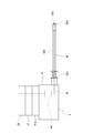
- FIG. 2 is a schematic side view of the lubricant injection hand 4 held by the holding unit 37 of the robot arm 22.
- the lubricant injection hand 4 includes an exterior frame 41, a downstream lubricant delivery path 42, a discharge portion 43, and a flow sensor 44.
- the exterior frame 41 is provided with a held portion 41 a that is held by the holding portion 37 of the robot arm 22.
- the exterior frame 41 supports the downstream-side lubricant delivery path 42, the discharge unit 43, and the flow sensor 44.
- the downstream-side lubricant delivery path 42 is connected to the upstream-side lubricant delivery path 25 when the held portion 41 a is held by the holding portion 37.
- the downstream lubricant delivery path 42 is supported by the exterior frame 41.
- the “lubricant delivery path” of the present invention is composed of an upstream lubricant delivery path 25 and a downstream lubricant delivery path 42, and guides the lubricant from the lubricant delivery device 24 to the discharge portion 43.
- the discharge unit 43 is sequentially connected to each of the plurality of inlets 117 of the articulated robot 100 that is the target machine, and discharges the lubricant.
- the connection between the discharge part 43 and the injection port 117 means that the lubricant discharged from the discharge part 43 is in a state of being injected into the lubricant injection point G.
- the discharge part 43 is formed in a pipe shape, and an opening at one end thereof is connected to the downstream lubricant delivery path 42.
- the discharge part 43 is supported by the exterior frame 41 and is formed so as to extend linearly from the exterior frame 41.
- the discharge part 43 is provided around the cushion mechanism 43a fixed to the exterior frame 41, the rod part 43b supported by the cushion mechanism 43a, the discharge port 43c provided at one end of the rod part 43b, and the discharge port 43c. And a sealed portion 43d.
- the cushion mechanism 43 a is configured by a coil spring, a linear bush, and the like, and supports the rod portion 43 b so as to be swingable in the longitudinal direction with respect to the exterior frame 41.
- the rod part 43b is hollow, and is formed so as to discharge the lubricant sent from the cushion mechanism 43a side from the discharge port 43c.
- the sealing portion 43d seals the injection port 117 with the discharge port 43c facing the internal space of the lubricant injection point G when the lubricant is injected into the lubricant injection point G.
- the sealing unit 43d is arranged to face the injection port 117 so that the rod portion 43b coincides with the injection direction of the injection port 117 by the operation of the robot arm 22. Thereafter, the sealing portion 43 d is pressed perpendicularly to the inlet 117 by the operation of the robot arm 22.
- the sealing portion 43d is made of, for example, urethane in order to improve airtightness.
- the flow rate sensor 44 detects the flow rate of the lubricant delivered from the lubricant delivery device 24 to the discharge unit 43.
- the flow rate sensor 44 is provided in the downstream lubricant delivery path 42.
- the flow rate information obtained by the flow rate sensor 44 is sent to the robot control unit 23 via a signal line (not shown).
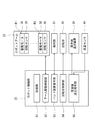
- FIG. 3 shows the control configuration of the robot controller 23.
- the robot control unit 23 not only controls the operation of the robot arm 22 but also controls each element related to the operation of injecting the lubricant into the lubricant injection point G.
- the robot control unit 23 is configured by an arithmetic unit such as a microcontroller or a logic circuit, for example.
- the robot control unit 23 includes a storage unit 51, an arm drive control unit 52, a hand attachment command unit 53, a turntable control unit 54, and a lubricant delivery command unit 55.
- the function blocks 51 to 55 are realized by operating according to a program or the like.
- the storage unit 51 stores various programs and information.
- the storage unit 51 stores an operation program for connecting the lubricant injection hand 4 to each of the plurality of injection ports 117 of the articulated robot 100 that is a target machine placed on the turntable 26. ing. Further, the storage unit 51 stores a target injection amount corresponding to each of the plurality of injection ports 117.
- the target injection amount is a target total amount of lubricant supplied to the lubricant injection point G through the corresponding injection port 117.
- the storage unit 51 also stores an operation program for rotating the turntable 26 and the like.
- the arm drive control unit 52 controls the drive motor 38 and the like so as to move the attached hand such as the lubricant injection hand 4 to the target position and orientation. To do.
- the rotation sensor 39 transmits an angular displacement signal related to the angular displacement amount of the corresponding drive motor 38 to the arm drive control unit 52, and the arm drive control unit 52 feeds back the operation of the drive motor 38 based on the received angular displacement signal. Control.
- the hand attachment command unit 53 controls attachment / detachment of the hand with the holding unit 37.
- the holding unit 37 is brought into contact with the hand, and then the hand mounting command unit 53 sends a signal to the holding unit 37 to hold the hand.
- the hand attachment instruction unit 53 holds the hand in the holding part 37 in a state where the hand attached to the robot arm 22 is accommodated in the hand pedestal 27. Send a signal to release the state.
- the turntable control unit 54 controls the operation of the rotation drive mechanism of the turntable 26 based on the operation program stored in the storage unit 51.
- the turntable controller 54 rotates the turntable 26 to move the injection port 117 of the target machine on the turntable 26 to a predetermined position.
- the lubricant delivery command unit 55 controls the start and stop of the delivery of the lubricant from the lubricant delivery device 24 to the lubricant injection hand 4.
- the lubricant supply command unit 55 controls the lubricant supply device 24 to start the supply of the lubricant.
- the lubricant delivery command unit 55 calculates the injection amount of the lubricant injected from the injection port 117 connected to the discharge unit 43 based on the flow rate information sent from the flow rate sensor 44 after the start of the delivery of the lubricant. .
- the lubricant delivery command unit 55 controls the lubricant delivery device 24 to stop the delivery of the lubricant.
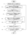
- FIG. 4 is a flowchart showing a control flow of the robot controller 23 in the lubricant injection operation by the lubricant injection system 1.
- the lubricant injection operation by the lubricant injection system 1 is started by placing the articulated robot 100 that is the target machine on the rotary base 26 in a predetermined state (posture, position, orientation, etc.).
- the storage unit 51 of the robot control unit 23 Before starting the lubricant injection operation by the lubricant injection system 1, the storage unit 51 of the robot control unit 23 stores the lubricant in each of the plurality of injection ports 117 of the articulated robot 2 placed on the turntable 26. An operation program for connecting the injection hand 4 is stored in advance. The storage unit 51 of the robot control unit 23 stores a target injection amount corresponding to each of the plurality of injection ports 117 in advance.
- the robot controller 23 attaches the lubricant injection hand 4 to the tip of the robot arm 22 (step S1). Specifically, the robot control unit 23 operates the drive motors 38 of the joint portions K1 to K6 to hold the tip of the robot arm 22 in the lubricant injection hand 4 accommodated in the hand table 27. The part 37 is brought into contact. Thereafter, a command is sent from the robot control unit 23 to the holding unit 37 to hold the lubricant injection hand 4, and the lubricant injection hand 4 is attached to the tip of the robot arm 22.
- the robot control unit 23 controls the turntable 26 and the robot arm 22 so that the discharge unit 43 is connected to the target injection port 117a as a target among the plurality of injection ports 117.
- the robot control unit 23 moves the turntable 26 so as to move the target inlet 117a to a predetermined position.
- the rotation is performed (step S2).
- the “predetermined position” is a predetermined position where the discharge unit 43 is connected to the injection port 117 according to the operation program stored in the storage unit 51 (for example, when the articulated robot 2 is taught).
- the robot control unit 23 operates the robot arm 22 to connect the discharge unit 43 of the lubricant injection hand 4 to the injection port 117 (step S3). Specifically, the robot control unit 23 controls the operation of the robot arm 22 to move the discharge unit 43 of the lubricant injection hand 4 and connect it to the target injection port 117a. As a result, the lubricant discharged from the discharge portion 43 is injected into the lubricant injection point G.
- the robot control unit 23 starts injection of the lubricant from the target injection port 117a to the lubricant injection point G (step S4). Specifically, the robot controller 23 sends a signal for starting the delivery of the lubricant to the lubricant delivery device 24 to start the delivery of the lubricant.
- the robot controller 23 starts calculating the injection amount of the lubricant injected into the lubricant injection point G based on the flow rate information sent from the flow sensor 44 (step S5). ).
- step S5 The calculated injection amount calculated in step S5 is compared with the target injection amount corresponding to the target injection port 117a (step S6). Steps S5 and S6 are repeated, for example, at predetermined intervals until the calculated injection amount reaches the corresponding target injection amount (NO in step S6).
- the robot controller 23 stops the injection of the lubricant from the target injection port 117a to the lubricant injection point G (step S7). Specifically, the robot controller 23 sends a signal for stopping the delivery of the lubricant to the lubricant delivery device 24 to stop the delivery of the lubricant. Thus, the injection of the lubricant from the target inlet 117a is completed.
- step S2 NO in step S8
- the discharge unit 43 is sequentially connected to the plurality of injection ports 117 of the target machine, and when the injection of the lubricant from all the injection ports 117 is completed (YES in step S8), the robot control unit 23
- the lubricant injection operation by the lubricant injection system 1 is completed. Note that the order of injecting the lubricant into the lubricant injection locations G1 to G6 depends on the information stored in the storage unit 51, but need not be in the order of the lubricant injection locations G1 to G6.
- the operation of the robot arm 22 is controlled by the robot control unit 23, and the discharge port 43 of the lubricant injection hand 4 is used as the injection port 117 of the articulated robot 100 that is the target machine. Connect to. For this reason, it is not necessary for the operator to manually perform the operation of attaching or removing the discharge portion 43 to or from the injection port 117. For this reason, the labor of the operation
- the robot controller 23 calculates the injection amount injected into the lubricant injection point G based on the flow rate information sent from the flow sensor 44. Since the delivery of the lubricant is stopped when the calculated injection amount reaches the target injection amount corresponding to the calculated injection amount, an accurate amount of lubricant can be injected for each injection port 117.
- the discharge unit 43 is sequentially connected to the injection port 117 by the robot arm 22. Therefore, even when a plurality of inlets 117 are scattered in the target machine as in the multi-joint robot 100, one lubricant delivery path that guides the lubricant from the lubricant delivery device 24 to the discharge unit 43.
- a simplified system with only can be constructed.
- connection of the discharge unit 43 to the injection port 117 of the target machine, start of injection of the lubricant into the lubricant injection point G, calculation of the injection amount, and target injection can all be performed by a control signal from the robot control unit 23. That is, the operator who performs the lubrication injection operation can operate only the robot controller 23 to perform the lubrication injection operation to all the injection ports 117 of the target machine.
- the operator who performs the lubrication injection operation can send the lubricant to the robot control unit 23.
- the lubricant injection operation of the target machine can be completed by only inputting the start command for the injection operation.
- the target machine is mounted on a rotary table 26 that is rotationally driven. For this reason, even if there is a case where the hand of the articulated robot 2 cannot be connected to the injection port 117 while the target machine is placed (position and orientation) due to the limitation of the operation range of the robot arm 22, the rotation is performed.
- the discharge unit 43 can be connected to all the injection ports 117 of the target machine by operating the platform 26 and the articulated robot 2 in a coordinated manner.
- the target machine is the articulated robot 100.
- the present invention is not limited to this, and the present invention is intended to lubricate industrial machines including various machine elements such as gears and bearings. Is possible.
- the lubricant was grease, it is not limited to this, For example, lubricating oil may be sufficient.
Landscapes
- Engineering & Computer Science (AREA)
- Mechanical Engineering (AREA)
- General Engineering & Computer Science (AREA)
- Robotics (AREA)
- Human Computer Interaction (AREA)
- Chemical & Material Sciences (AREA)
- Combustion & Propulsion (AREA)
- Manipulator (AREA)
Abstract
Description
2 多関節ロボット
21 基台
22 ロボットアーム
23 ロボット制御部
24 潤滑剤送出装置
25 上流側潤滑剤送出路
31 第1アーム体
32 第2アーム体
33 第3アーム体
34 第4アーム体
35 第5アーム体
36 第6アーム体
4 潤滑剤注入用ハンド
42 下流側潤滑剤送出路
43 吐出部
44 流量センサ
100 多関節ロボット(対象機械)
117 注入口
G1~G6 潤滑剤注入箇所
Claims (1)
- 複数の注入口を有する対象機械に潤滑剤を注入する潤滑剤注入システムであって、
基台と、
前記基台から順次連結された複数のアーム体を含むロボットアームと、
前記複数の注入口のそれぞれに順次接続されて潤滑剤を吐出する吐出部を有しており、前記ロボットアームの先端部に着脱可能に装着される潤滑剤注入用ハンドと、
前記ロボットアームの動作を制御するロボット制御部と、
前記ロボット制御部により潤滑剤の送出が制御される潤滑剤送出装置と、
前記潤滑剤送出装置から前記吐出部に潤滑剤を導く潤滑剤送出路と、
前記潤滑剤送出路に設けられ、検知した流量情報を前記ロボット制御部へと送る流量センサと、を備え、
前記ロボット制御部は、
前記複数の注入口のそれぞれに対応する目標注入量を記憶しており、
前記複数の注入口のいずれかに前記吐出部が接続されたとき、潤滑剤の送出を開始するように前記潤滑剤送出装置を制御し、
前記吐出部と接続された注入口から注入された潤滑剤の注入量を、前記流量センサから送られる前記流量情報から算出し、
算出された注入量が、前記吐出部と接続された注入口に対応する前記目標注入量に達したとき、潤滑剤の送出を停止するように前記潤滑剤送出装置を制御する、潤滑剤注入システム。
Priority Applications (3)
| Application Number | Priority Date | Filing Date | Title |
|---|---|---|---|
| US15/576,324 US10605404B2 (en) | 2015-05-22 | 2016-05-16 | Lubricant injection system |
| KR1020177035977A KR101949383B1 (ko) | 2015-05-22 | 2016-05-16 | 윤활제 주입 시스템 |
| CN201680029552.2A CN107530883B (zh) | 2015-05-22 | 2016-05-16 | 润滑剂注入系统 |
Applications Claiming Priority (2)
| Application Number | Priority Date | Filing Date | Title |
|---|---|---|---|
| JP2015-104852 | 2015-05-22 | ||
| JP2015104852A JP6691353B2 (ja) | 2015-05-22 | 2015-05-22 | 潤滑剤注入システム |
Publications (1)
| Publication Number | Publication Date |
|---|---|
| WO2016189825A1 true WO2016189825A1 (ja) | 2016-12-01 |
Family
ID=57393873
Family Applications (1)
| Application Number | Title | Priority Date | Filing Date |
|---|---|---|---|
| PCT/JP2016/002386 Ceased WO2016189825A1 (ja) | 2015-05-22 | 2016-05-16 | 潤滑剤注入システム |
Country Status (6)
| Country | Link |
|---|---|
| US (1) | US10605404B2 (ja) |
| JP (1) | JP6691353B2 (ja) |
| KR (1) | KR101949383B1 (ja) |
| CN (1) | CN107530883B (ja) |
| TW (1) | TWI596294B (ja) |
| WO (1) | WO2016189825A1 (ja) |
Cited By (1)
| Publication number | Priority date | Publication date | Assignee | Title |
|---|---|---|---|---|
| CN112405614A (zh) * | 2020-10-26 | 2021-02-26 | 广东凯宝机器人科技有限公司 | 一种六轴机器人加油引流装置 |
Families Citing this family (8)
| Publication number | Priority date | Publication date | Assignee | Title |
|---|---|---|---|---|
| JP6691353B2 (ja) * | 2015-05-22 | 2020-04-28 | 川崎重工業株式会社 | 潤滑剤注入システム |
| DE102017221397A1 (de) * | 2017-11-29 | 2019-05-29 | Krones Ag | Transportanlage für Behälter in der Getränkeindustrie und Schmierverfahren |
| CN108943019A (zh) * | 2018-07-23 | 2018-12-07 | 烟台知兴知识产权咨询服务有限公司 | 一种机器人关节润滑油注射装置 |
| DE102019214981B4 (de) * | 2019-09-30 | 2021-10-14 | Sms Group Gmbh | Schmiermittel-Applikator an einer als Strang- Rohr- oder Lochpresse ausgebildeten Metallpresse, Strang- Rohr- oder Lochpresse sowie Verfahren zur Schmierung eines Dorns an einer Strang- Rohr- oder Lochpresse |
| CN110822269A (zh) * | 2019-10-16 | 2020-02-21 | 上海申苏船舶修造有限公司 | 一种用于烧结机的智能给脂装置及其控制方法 |
| CN112192572B (zh) * | 2020-10-13 | 2021-08-10 | 浙江树人学院(浙江树人大学) | 一种多任务协同装置及其控制方法 |
| CN113547514B (zh) * | 2021-07-12 | 2022-08-26 | 烟台工程职业技术学院(烟台市技师学院) | 自动上下料机械臂 |
| US12276081B2 (en) * | 2022-06-06 | 2025-04-15 | Caterpillar Inc. | Lubrication distribution system for machine with kinematic linkages |
Citations (4)
| Publication number | Priority date | Publication date | Assignee | Title |
|---|---|---|---|---|
| JPH04240091A (ja) * | 1991-01-17 | 1992-08-27 | Toyoda Mach Works Ltd | 給油装置付ロボット |
| JP2000176985A (ja) * | 1998-12-16 | 2000-06-27 | Niigata Eng Co Ltd | 射出成形機における自動潤滑装置 |
| US20080274865A1 (en) * | 2005-09-23 | 2008-11-06 | Thomas Sturm | Processing Plant |
| JP2013006244A (ja) * | 2011-06-24 | 2013-01-10 | Nissan Motor Co Ltd | ロボットセルの位置合わせ方法及び位置合わせ制御装置 |
Family Cites Families (18)
| Publication number | Priority date | Publication date | Assignee | Title |
|---|---|---|---|---|
| JPH1133949A (ja) * | 1997-07-14 | 1999-02-09 | Fanuc Ltd | 産業用ロボット |
| JP3961662B2 (ja) * | 1998-04-08 | 2007-08-22 | アイシン軽金属株式会社 | プランジャーチップ用潤滑剤供給装置 |
| KR100470874B1 (ko) * | 2002-10-30 | 2005-02-21 | (주)현보 | 윤활유 자동 공급장치 |
| CN1898037B (zh) * | 2003-12-24 | 2010-05-26 | 住友金属工业株式会社 | 润滑剂供给系统、无缝管的制造装置及无缝管的制造方法 |
| JP2006002790A (ja) | 2004-06-15 | 2006-01-05 | Nsk Ltd | 潤滑剤供給装置 |
| JP2006334700A (ja) * | 2005-05-31 | 2006-12-14 | Nippei Toyama Corp | 加工システム |
| US8161650B2 (en) * | 2007-10-02 | 2012-04-24 | Android Industries Llc | Workcell for tire and wheel assembly including a tire inflating sub-station that utilizes a flexible flip seal |
| KR101189543B1 (ko) * | 2010-06-07 | 2012-10-11 | 한전케이피에스 주식회사 | 그리스 주유기 및 이를 이용한 주유 관리시스템 |
| KR101261544B1 (ko) * | 2011-01-21 | 2013-05-07 | (주)세스텍 | 그리스 주입장치 |
| CN102306575A (zh) * | 2011-03-30 | 2012-01-04 | 黄道铭 | 汽车玻璃升降器开关自动装配机推杆进料润滑装置 |
| WO2013159046A1 (en) * | 2012-04-20 | 2013-10-24 | National Oilwell Varco, L.P. | Centrifugal applicator |
| EP2754908B1 (en) * | 2013-01-10 | 2018-01-10 | GE Renewable Technologies | Lubrication systems for bearing assemblies |
| JP6131106B2 (ja) * | 2013-05-27 | 2017-05-17 | 東芝機械株式会社 | ダイカスト成形機の被覆剤供給装置 |
| JP6691353B2 (ja) * | 2015-05-22 | 2020-04-28 | 川崎重工業株式会社 | 潤滑剤注入システム |
| JP6626271B2 (ja) * | 2015-05-22 | 2019-12-25 | 川崎重工業株式会社 | リークチェックシステム及びそれを用いたリークチェック方法 |
| JP6812925B2 (ja) * | 2017-08-01 | 2021-01-13 | トヨタ自動車株式会社 | ロボットアーム、鉄粉量推定方法及び異常予兆判定システム |
| JP6670454B2 (ja) * | 2017-08-18 | 2020-03-25 | 株式会社安川電機 | ロボット及びロボットシステム |
| JP6919607B2 (ja) * | 2018-03-15 | 2021-08-18 | オムロン株式会社 | ロボットシステム、およびロボットの制御方法 |
-
2015
- 2015-05-22 JP JP2015104852A patent/JP6691353B2/ja active Active
-
2016
- 2016-05-16 KR KR1020177035977A patent/KR101949383B1/ko active Active
- 2016-05-16 WO PCT/JP2016/002386 patent/WO2016189825A1/ja not_active Ceased
- 2016-05-16 US US15/576,324 patent/US10605404B2/en active Active
- 2016-05-16 CN CN201680029552.2A patent/CN107530883B/zh active Active
- 2016-05-18 TW TW105115305A patent/TWI596294B/zh active
Patent Citations (4)
| Publication number | Priority date | Publication date | Assignee | Title |
|---|---|---|---|---|
| JPH04240091A (ja) * | 1991-01-17 | 1992-08-27 | Toyoda Mach Works Ltd | 給油装置付ロボット |
| JP2000176985A (ja) * | 1998-12-16 | 2000-06-27 | Niigata Eng Co Ltd | 射出成形機における自動潤滑装置 |
| US20080274865A1 (en) * | 2005-09-23 | 2008-11-06 | Thomas Sturm | Processing Plant |
| JP2013006244A (ja) * | 2011-06-24 | 2013-01-10 | Nissan Motor Co Ltd | ロボットセルの位置合わせ方法及び位置合わせ制御装置 |
Cited By (2)
| Publication number | Priority date | Publication date | Assignee | Title |
|---|---|---|---|---|
| CN112405614A (zh) * | 2020-10-26 | 2021-02-26 | 广东凯宝机器人科技有限公司 | 一种六轴机器人加油引流装置 |
| CN112405614B (zh) * | 2020-10-26 | 2024-04-05 | 东莞市达林自动化科技有限公司 | 一种六轴机器人加油引流装置 |
Also Published As
| Publication number | Publication date |
|---|---|
| CN107530883A (zh) | 2018-01-02 |
| TW201704677A (zh) | 2017-02-01 |
| KR101949383B1 (ko) | 2019-02-19 |
| CN107530883B (zh) | 2020-07-10 |
| TWI596294B (zh) | 2017-08-21 |
| KR20180008628A (ko) | 2018-01-24 |
| US10605404B2 (en) | 2020-03-31 |
| JP2016215344A (ja) | 2016-12-22 |
| US20180156384A1 (en) | 2018-06-07 |
| JP6691353B2 (ja) | 2020-04-28 |
Similar Documents
| Publication | Publication Date | Title |
|---|---|---|
| JP6691353B2 (ja) | 潤滑剤注入システム | |
| US10571357B2 (en) | Leak check system and method of checking leak using the same | |
| TWI580479B (zh) | A nozzle rotating mechanism and a coating device provided with the same | |
| CN111032233B (zh) | 涂敷系统、作业系统及姿势变化单元 | |
| CN104209294A (zh) | 直交多关节复合型cnc清洗机及其清洗方法 | |
| AU2005242222B2 (en) | Control system | |
| JP4945262B2 (ja) | 車両用ガラス取付装置及び車両用ガラスの移動方法 | |
| WO2015107567A1 (ja) | 液体供給装置 | |
| CN104440942A (zh) | 机器人 | |
| JP6647308B2 (ja) | 多関節ロボットのティーチングシステム | |
| KR20150129172A (ko) | 도장로봇용 선회장치 및 이를 포함하는 도장로봇 | |
| EP4005730A1 (en) | Machine tool with an automatic lubricating system and related lubricating method | |
| KR102279410B1 (ko) | 실링부재의 손상을 방지할 수 있는 로봇 | |
| JP5416827B1 (ja) | 液体供給装置 | |
| CN111201109B (zh) | 焊接装置 | |
| JP6694853B2 (ja) | 熱処理装置 | |
| JP2022085273A (ja) | 潤滑剤供給システム、潤滑剤の供給方法、産業機械の製造方法、及び多関節ロボットの製造方法 | |
| ITBO970316A1 (it) | Metodo e macchina per l'assemblaggio di riduttori. | |
| JP6741544B2 (ja) | ロボット | |
| JP2012086319A (ja) | 産業用ロボットの速度位置解析システム及び産業用ロボットの速度位置検出装置 | |
| CN110997254A (zh) | 机器人 | |
| KR20090106179A (ko) | 기계장치의 부품 세정기 | |
| KR20160009790A (ko) | 도장로봇용 구동장치 및 이를 포함하는 도장로봇 | |
| JPH03270847A (ja) | 移動系の自動給油装置 | |
| JP2008195431A (ja) | 液体供給装置及び液体供給装置の維持方法 |
Legal Events
| Date | Code | Title | Description |
|---|---|---|---|
| 121 | Ep: the epo has been informed by wipo that ep was designated in this application |
Ref document number: 16799539 Country of ref document: EP Kind code of ref document: A1 |
|
| WWE | Wipo information: entry into national phase |
Ref document number: 15576324 Country of ref document: US |
|
| NENP | Non-entry into the national phase |
Ref country code: DE |
|
| ENP | Entry into the national phase |
Ref document number: 20177035977 Country of ref document: KR Kind code of ref document: A |
|
| 122 | Ep: pct application non-entry in european phase |
Ref document number: 16799539 Country of ref document: EP Kind code of ref document: A1 |