WO2016189822A1 - ワーク搬送システム - Google Patents
ワーク搬送システム Download PDFInfo
- Publication number
- WO2016189822A1 WO2016189822A1 PCT/JP2016/002383 JP2016002383W WO2016189822A1 WO 2016189822 A1 WO2016189822 A1 WO 2016189822A1 JP 2016002383 W JP2016002383 W JP 2016002383W WO 2016189822 A1 WO2016189822 A1 WO 2016189822A1
- Authority
- WO
- WIPO (PCT)
- Prior art keywords
- workpiece
- claws
- grip portion
- engagement plate
- gripping
- Prior art date
- Legal status (The legal status is an assumption and is not a legal conclusion. Google has not performed a legal analysis and makes no representation as to the accuracy of the status listed.)
- Ceased
Links
Images



Classifications
-
- B—PERFORMING OPERATIONS; TRANSPORTING
- B25—HAND TOOLS; PORTABLE POWER-DRIVEN TOOLS; MANIPULATORS
- B25J—MANIPULATORS; CHAMBERS PROVIDED WITH MANIPULATION DEVICES
- B25J15/00—Gripping heads and other end effectors
- B25J15/0033—Gripping heads and other end effectors with gripping surfaces having special shapes
-
- B—PERFORMING OPERATIONS; TRANSPORTING
- B25—HAND TOOLS; PORTABLE POWER-DRIVEN TOOLS; MANIPULATORS
- B25J—MANIPULATORS; CHAMBERS PROVIDED WITH MANIPULATION DEVICES
- B25J15/00—Gripping heads and other end effectors
- B25J15/0033—Gripping heads and other end effectors with gripping surfaces having special shapes
- B25J15/0038—Cylindrical gripping surfaces
-
- B—PERFORMING OPERATIONS; TRANSPORTING
- B25—HAND TOOLS; PORTABLE POWER-DRIVEN TOOLS; MANIPULATORS
- B25J—MANIPULATORS; CHAMBERS PROVIDED WITH MANIPULATION DEVICES
- B25J15/00—Gripping heads and other end effectors
- B25J15/08—Gripping heads and other end effectors having finger members
-
- B—PERFORMING OPERATIONS; TRANSPORTING
- B25—HAND TOOLS; PORTABLE POWER-DRIVEN TOOLS; MANIPULATORS
- B25J—MANIPULATORS; CHAMBERS PROVIDED WITH MANIPULATION DEVICES
- B25J15/00—Gripping heads and other end effectors
- B25J15/08—Gripping heads and other end effectors having finger members
- B25J15/10—Gripping heads and other end effectors having finger members with three or more finger members
-
- B—PERFORMING OPERATIONS; TRANSPORTING
- B25—HAND TOOLS; PORTABLE POWER-DRIVEN TOOLS; MANIPULATORS
- B25J—MANIPULATORS; CHAMBERS PROVIDED WITH MANIPULATION DEVICES
- B25J15/00—Gripping heads and other end effectors
- B25J15/08—Gripping heads and other end effectors having finger members
- B25J15/10—Gripping heads and other end effectors having finger members with three or more finger members
- B25J15/103—Gripping heads and other end effectors having finger members with three or more finger members for gripping the object in three contact points
-
- B—PERFORMING OPERATIONS; TRANSPORTING
- B25—HAND TOOLS; PORTABLE POWER-DRIVEN TOOLS; MANIPULATORS
- B25J—MANIPULATORS; CHAMBERS PROVIDED WITH MANIPULATION DEVICES
- B25J9/00—Program-controlled manipulators
- B25J9/02—Program-controlled manipulators characterised by movement of the arms, e.g. cartesian coordinate type
- B25J9/04—Program-controlled manipulators characterised by movement of the arms, e.g. cartesian coordinate type by rotating at least one arm, excluding the head movement itself, e.g. cylindrical coordinate type or polar coordinate type
- B25J9/041—Cylindrical coordinate type
- B25J9/042—Cylindrical coordinate type comprising an articulated arm
-
- Y—GENERAL TAGGING OF NEW TECHNOLOGICAL DEVELOPMENTS; GENERAL TAGGING OF CROSS-SECTIONAL TECHNOLOGIES SPANNING OVER SEVERAL SECTIONS OF THE IPC; TECHNICAL SUBJECTS COVERED BY FORMER USPC CROSS-REFERENCE ART COLLECTIONS [XRACs] AND DIGESTS
- Y10—TECHNICAL SUBJECTS COVERED BY FORMER USPC
- Y10S—TECHNICAL SUBJECTS COVERED BY FORMER USPC CROSS-REFERENCE ART COLLECTIONS [XRACs] AND DIGESTS
- Y10S901/00—Robots
- Y10S901/30—End effector
Definitions
- the present invention relates to a workpiece transfer system using a robot.
- Patent Document 1 discloses a workpiece transfer system in which a chuck device is attached to a robot.
- the chuck device has a pair of claws in which a V-shaped depression is formed on a work contact surface for gripping a cylindrical work.
- some chuck devices have three claws with a flat workpiece contact surface.
- the center of gravity of the work body is not necessarily located at the center of the gripping portion. Therefore, when the workpiece is transported by the robot, the rotational force around the gripping portion acts on the workpiece due to the inertial force during acceleration or deceleration. For this reason, there is a possibility that the workpiece rotates (that is, the workpiece cannot be conveyed to a proper position) only by gripping the grip portion with the three claws.
- an object of the present invention is to provide a workpiece transfer system that can prevent rotation of a workpiece when a workpiece including a workpiece main body and a gripping portion is transferred by a robot.
- a workpiece conveyance system of the present invention includes a workpiece including a workpiece main body, a cylindrical gripping portion protruding from the workpiece main body, and an engagement plate attached to a front end surface of the gripping portion; A chuck device including three claws for gripping the grip portion from the radial direction of the grip portion; and a robot to which the chuck device is attached; and the engagement plate is disposed along the distal end surface of the grip portion.
- An engagement groove into which one of the three claws is fitted is formed in the extension part.
- the workpiece can be prevented from rotating by fitting one claw of the chuck device into the engagement groove of the engagement plate.
- the above effect can be obtained with a simple configuration in which the engagement plate is attached to the grip portion.
- the engaging plate has a shape in which the projecting portion projects only in the direction from the gripping portion toward one of the three claws, and fits within the outline of the gripping portion in a region corresponding to the remaining two claws. Also good. According to this configuration, the engagement plate can be minimized.
- the robot may include an articulated arm having a plurality of degrees of freedom.
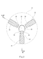
- FIG. 2 is a cross-sectional plan view taken along line II-II in FIG. 1 immediately before the chuck device grips a workpiece gripping portion.
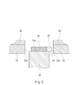
- FIG. 3 is a sectional side view taken along line III-III in FIG. 2.
- FIG. 2 is a cross-sectional plan view taken along line II-II in FIG. 1 immediately after the chuck device grips a workpiece gripping portion.
- FIG. 5 is a cross-sectional side view taken along line VV in FIG. 4. It is a cross-sectional top view of the workpiece conveyance system of a modification.
- FIG. 7 is a sectional side view taken along line VII-VII in FIG. 6.
- FIG. 1 shows a workpiece transfer system 1 according to an embodiment of the present invention.
- the workpiece transfer system 1 includes a workpiece 2 and a robot 4 that transfers the workpiece 2.
- the workpiece 2 includes a workpiece main body 21, a columnar gripping portion 22 protruding from the workpiece main body 21, and an engagement plate 23 attached to a distal end surface 22a (see FIG. 3) of the gripping portion 22.
- the work main body 21 has a plate shape, and the gripping portion 22 protrudes in the thickness direction of the work main body 21 in the vicinity of the edge of the work main body 21.
- the distal end surface 22 a of the gripping portion 22 is orthogonal to the central axis of the gripping portion 22, and the engagement plate 23 is parallel to the distal end surface 22 a of the gripping portion 22.
- the robot 4 includes an articulated arm 41 having a plurality of degrees of freedom.
- the chuck device 3 is attached to the articulated arm 41.
- the robot 4 is not limited to the one including the articulated arm 41, and may be a uniaxial robot such as a linear actuator, for example.
- the chuck device 3 supports the three claws 33 that grip the grip portion 22 from the radial direction of the grip portion 22, the three sliders 32 to which the claws 33 are fixed, and the slider 32.
- a chuck body 31 is included.
- the chuck body 31 is formed with three grooves extending in the radial direction from the center of the chuck body 31 at intervals of 120 degrees, and the slider 32 is fitted in these grooves.
- Each claw 33 has substantially the same shape as the slider 32. However, in the radial direction of the chuck body 31, the inner end portion of each claw 33 is tapered so that the width is narrower than the slider 32.
- One of the three claws 33 (the lower claw in FIG. 2) is also a rotation preventing claw.
- each claw 33 has a flat work contact surface 33 a that is orthogonal to the radial direction of the chuck body 31.
- the chuck device 3 grips the grip portion 22 in a state where the tip end surface 22a of the grip portion 22 is located at an intermediate position of the workpiece contact surface 33a.
- the claw 33 grips a portion of the grip portion 22 adjacent to the tip surface 22a.
- the engagement plate 23 described above includes an overhanging portion 24 that protrudes from the grip portion 22 along the distal end surface 22a of the grip portion 22, as shown in FIG.
- the engagement plate 23 projects only in the direction in which the projecting portion 24 is directed from the gripping portion 22 to one of the three claws 33 (the lower claw in FIG. 2), and corresponds to the remaining two claws 33.
- the region has a shape that fits within the outline of the gripping portion 22.
- the overhanging portion 24 is formed with an engagement groove 25 into which one of the three claws 33 (a claw for preventing rotation) is fitted.
- the width of the engaging groove 25 is substantially equal to the width of the inner end of the claw 33 for preventing rotation.
- the depth of the engagement groove 25 in the radial direction of the grip portion 22 is greater than the distance from the grip portion 22 to the tip of the overhang portion 24. For this reason, a part of the front end surface 22 a of the grip portion 22 is exposed upward through the engagement groove 25.
- the articulated arm 41 moves the chuck device 3 directly above the grip portion 22. Thereafter, the articulated arm 41 lowers the chuck device 3 and inserts the upper end portion of the grip portion 22 into the inside of the three claws 33. Accordingly, the positional relationship between the three claws 33 and the engagement plate 23 is as shown in FIGS.
- the chuck device 3 moves the three claws 33 together with the slider 32 radially inward. Accordingly, the positional relationship between the three claws 33 and the engagement plate 23 is as shown in FIGS. 4 and 5. That is, in FIG. 2, the lower claw 33 is fitted into the engagement groove 25 of the engagement plate 23. Therefore, the lower claw 33 in FIG. 2 also functions as a positioning claw. Further, since the three claws 33 move inward in the radial direction in synchronization, the center of the grip portion 22 automatically coincides with the center of the chuck body 31 by the movement of the three claws inward in the radial direction.
- the one claw 33 of the chuck device 3 fits into the engagement groove 25 of the engagement plate 23, thereby preventing the workpiece 2 from rotating.
- the above effect can be obtained with a simple configuration in which the engagement plate 23 is attached to the grip portion 22.
- the robot 4 includes the multi-joint arm 41 as in the present embodiment, the inertial force acts on the workpiece 2 not only when the conveyance is accelerated and decelerated, but also when the workpiece 2 is turning. Remarkably can be obtained.
- the tolerance between the width of the engagement groove 25 and the width of the claw 33 for preventing rotation is tightened (in other words, their width). Width can be matched with high accuracy). As a result, the rotation of the workpiece 2 can be extremely effectively prevented.
- each claw 33 has a workpiece contact surface 33 a that contacts the side surface of the grip portion 22 below the tip surface 22 a of the grip portion 22, and the workpiece contact surface 33 a.
- You may have the recessed part 33b above.
- the claw 33 may grip a portion of the grip portion 22 away from the tip surface 22a.
- the overhang portion 24 may overhang the entire circumference from the grip portion 22.
- the engagement plate 23 can be minimized if the overhanging portion 24 protrudes in only one direction from the gripping portion 22 as in the above embodiment.
Landscapes
- Engineering & Computer Science (AREA)
- Robotics (AREA)
- Mechanical Engineering (AREA)
- Manipulator (AREA)
Abstract
Description
本発明は上述した実施形態に限定されるものではなく、本発明の要旨を逸脱しない範囲で種々の変形が可能である。
2 ワーク
21 ワーク本体
22 把持部
22a 先端面
23 係合板
24 張り出し部
25 係合溝
3 チャック装置
33 爪
4 ロボット
41 多関節アーム
Claims (3)
- ワーク本体、前記ワーク本体から突出する円柱状の把持部、および前記把持部の先端面に取り付けられた係合板、を含むワークと、
前記把持部を当該把持部の径方向から掴む3つの爪を含むチャック装置と、
前記チャック装置が取り付けられるロボットと、を備え、
前記係合板は、前記把持部の先端面に沿って前記把持部から張り出す張り出し部を含み、前記張り出し部には、前記3つの爪の1つが嵌まり込む係合溝が形成されている、ワーク搬送システム。 - 前記係合板は、前記張り出し部が前記把持部から前記3つの爪の1つに向かう方向のみに張り出し、残りの2つの爪に対応する領域では前記把持部の輪郭内に収まる形状を有する、請求項1に記載のワーク搬送システム。
- 前記ロボットは、複数の自由度を持つ多関節アームを含む、請求項1または2に記載のワーク搬送システム。
Priority Applications (3)
| Application Number | Priority Date | Filing Date | Title |
|---|---|---|---|
| US15/576,302 US10179412B2 (en) | 2015-05-22 | 2016-05-16 | Workpiece conveying system |
| CN201680029498.1A CN107614211B (zh) | 2015-05-22 | 2016-05-16 | 工件搬送系统 |
| KR1020177036228A KR102014914B1 (ko) | 2015-05-22 | 2016-05-16 | 워크 반송 시스템 |
Applications Claiming Priority (2)
| Application Number | Priority Date | Filing Date | Title |
|---|---|---|---|
| JP2015104697A JP6581391B2 (ja) | 2015-05-22 | 2015-05-22 | ワーク搬送システム |
| JP2015-104697 | 2015-05-22 |
Publications (1)
| Publication Number | Publication Date |
|---|---|
| WO2016189822A1 true WO2016189822A1 (ja) | 2016-12-01 |
Family
ID=57392664
Family Applications (1)
| Application Number | Title | Priority Date | Filing Date |
|---|---|---|---|
| PCT/JP2016/002383 Ceased WO2016189822A1 (ja) | 2015-05-22 | 2016-05-16 | ワーク搬送システム |
Country Status (6)
| Country | Link |
|---|---|
| US (1) | US10179412B2 (ja) |
| JP (1) | JP6581391B2 (ja) |
| KR (1) | KR102014914B1 (ja) |
| CN (1) | CN107614211B (ja) |
| TW (1) | TWI613053B (ja) |
| WO (1) | WO2016189822A1 (ja) |
Families Citing this family (9)
| Publication number | Priority date | Publication date | Assignee | Title |
|---|---|---|---|---|
| JP6735149B2 (ja) * | 2016-05-11 | 2020-08-05 | オークマ株式会社 | 工作機械 |
| JP7334477B2 (ja) * | 2019-05-31 | 2023-08-29 | 京セラドキュメントソリューションズ株式会社 | 組立装置 |
| CN112971461B (zh) * | 2021-02-20 | 2022-06-03 | 江西金虎保险设备集团有限公司 | 一种博物馆展示用旋转观赏文物柜 |
| JP7620109B2 (ja) * | 2021-07-20 | 2025-01-22 | 株式会社Fuji | ロボットハンドのワーク把持判定機構 |
| PL247671B1 (pl) * | 2021-09-30 | 2025-08-18 | Fud Tech Spolka Z Ograniczona Odpowiedzialnoscia | Sposób podnoszenia przedmiotów wielkogabarytowych, zespół zblocza do takiego podnoszenia i uchwyt bezobsługowy zespołu zblocza |
| JP7747579B2 (ja) * | 2022-04-18 | 2025-10-01 | トヨタ自動車株式会社 | ワークの搬送装置 |
| US20240222680A1 (en) * | 2022-12-28 | 2024-07-04 | Rivian Ip Holdings, Llc | Battery manufacturing apparatus and methods |
| CN117564426B (zh) * | 2023-12-12 | 2026-06-30 | 中国航空制造技术研究院 | 用于自动化电阻点焊的柔性自定位装置及其使用方法 |
| GB202500682D0 (en) * | 2025-01-17 | 2025-03-05 | Cellular Origins Ltd | Automated bioprocessing systems |
Citations (3)
| Publication number | Priority date | Publication date | Assignee | Title |
|---|---|---|---|---|
| JPH0240455U (ja) * | 1988-09-09 | 1990-03-19 | ||
| JPH05389U (ja) * | 1991-06-25 | 1993-01-08 | 日本電気株式会社 | パレツト用ハンド |
| JPH0752070A (ja) * | 1993-06-01 | 1995-02-28 | Sekisui Chem Co Ltd | 試料把持装置 |
Family Cites Families (17)
| Publication number | Priority date | Publication date | Assignee | Title |
|---|---|---|---|---|
| US2489864A (en) * | 1948-08-17 | 1949-11-29 | Pittsburgh Plate Glass Co | Automatic coupling |
| FR1329072A (fr) * | 1962-04-27 | 1963-06-07 | Commissariat Energie Atomique | Pince automatique de préhension pour la manutention de charges |
| JPS4741806Y1 (ja) * | 1972-01-18 | 1972-12-18 | ||
| DE2937061C2 (de) * | 1979-09-13 | 1981-11-12 | Pfaff Industriemaschinen Gmbh, 6750 Kaiserslautern | Handhabungsgerät mit einer Greifvorrichtung |
| US4697839A (en) * | 1986-11-28 | 1987-10-06 | General Motors Corporation | Flexible part-centering pneumatic gripper |
| JPH0523989A (ja) * | 1991-07-15 | 1993-02-02 | Hitachi Ltd | 宇宙ロボツト用のマグネツト式エンドエフエクタ |
| US5320395A (en) * | 1992-09-25 | 1994-06-14 | Oceaneering International, Inc. | Microconical interface fitting and interface grasping tool |
| JPH07156086A (ja) | 1993-12-01 | 1995-06-20 | Toyota Motor Corp | ワーク搬送装置 |
| US6257636B1 (en) * | 2000-06-02 | 2001-07-10 | The United States Of America As Represented By The United States Department Of Energy | Self-actuating mechanical grapple for lifting and handling objects |
| US6857174B2 (en) * | 2002-01-15 | 2005-02-22 | Denso Corporation | Robot hand for high load work |
| US7648183B2 (en) * | 2006-03-22 | 2010-01-19 | Cornwell Carl R | Latching apparatus and method |
| TW201105470A (en) * | 2009-08-10 | 2011-02-16 | Hon Hai Prec Ind Co Ltd | Fixture replacing structure |
| JP2012152860A (ja) * | 2011-01-26 | 2012-08-16 | Toyota Motor Corp | 把持装置およびその制御方法 |
| JP5890623B2 (ja) * | 2011-06-28 | 2016-03-22 | 株式会社安川電機 | 液体処理システム及び液体処理方法 |
| CN103619530B (zh) * | 2011-07-07 | 2016-01-13 | 株式会社安川电机 | 末端执行器和机器人 |
| CN102357886B (zh) * | 2011-08-31 | 2013-12-25 | 日立电梯电机(广州)有限公司 | 机械手及工件抓取翻转装置 |
| US9440358B2 (en) * | 2012-05-23 | 2016-09-13 | Northrop Grumman Systems Corporation | Robotic tool change system |
-
2015
- 2015-05-22 JP JP2015104697A patent/JP6581391B2/ja active Active
-
2016
- 2016-05-16 CN CN201680029498.1A patent/CN107614211B/zh active Active
- 2016-05-16 WO PCT/JP2016/002383 patent/WO2016189822A1/ja not_active Ceased
- 2016-05-16 US US15/576,302 patent/US10179412B2/en active Active
- 2016-05-16 KR KR1020177036228A patent/KR102014914B1/ko active Active
- 2016-05-18 TW TW105115308A patent/TWI613053B/zh active
Patent Citations (3)
| Publication number | Priority date | Publication date | Assignee | Title |
|---|---|---|---|---|
| JPH0240455U (ja) * | 1988-09-09 | 1990-03-19 | ||
| JPH05389U (ja) * | 1991-06-25 | 1993-01-08 | 日本電気株式会社 | パレツト用ハンド |
| JPH0752070A (ja) * | 1993-06-01 | 1995-02-28 | Sekisui Chem Co Ltd | 試料把持装置 |
Also Published As
| Publication number | Publication date |
|---|---|
| TW201700242A (zh) | 2017-01-01 |
| US10179412B2 (en) | 2019-01-15 |
| US20180147730A1 (en) | 2018-05-31 |
| KR102014914B1 (ko) | 2019-08-27 |
| CN107614211A (zh) | 2018-01-19 |
| TWI613053B (zh) | 2018-02-01 |
| CN107614211B (zh) | 2020-07-17 |
| JP2016215340A (ja) | 2016-12-22 |
| KR20180008697A (ko) | 2018-01-24 |
| JP6581391B2 (ja) | 2019-09-25 |
Similar Documents
| Publication | Publication Date | Title |
|---|---|---|
| JP6581391B2 (ja) | ワーク搬送システム | |
| EP2666599B1 (en) | Robot hand, robot, and method for manufacturing workpiece | |
| WO2009037675A3 (en) | Transfer mechanism with multiple wafer handling capability | |
| CN106457576B (zh) | 末端执行器、工业用机器人及其运转方法 | |
| KR20160068398A (ko) | 부품의 적재시스템 | |
| CN103056681B (zh) | 一种用于设置在吸盘上的夹具 | |
| TWI714770B (zh) | 夾持裝置 | |
| WO2017054995A3 (de) | Transportvorrichtung zum transportieren eines werkstücks | |
| JP2018192570A (ja) | 工作機械 | |
| JP2020517104A5 (ja) | ||
| JP6255259B2 (ja) | 搬送機構 | |
| JP5592916B2 (ja) | ワーク把持装置 | |
| JP5711697B2 (ja) | 工具保持部材 | |
| KR102722143B1 (ko) | 그리퍼의 탈착 및 회전 장치 | |
| JP2015150649A (ja) | チャック装置 | |
| JP6554784B2 (ja) | ロボットハンド、ロボット及びロボットシステム | |
| TWI571367B (zh) | Clamping mechanism | |
| JP2008264943A (ja) | 搬送・作業システム及び搬送・作業方法 | |
| US20220063034A1 (en) | Gripping machine for articles | |
| JP2002066813A (ja) | チャックのスペーサ及びスペーサを使用した加工方法 | |
| CN108290262A (zh) | 工件移送装置 | |
| JP5694267B2 (ja) | チャック | |
| JP2015066655A (ja) | 引き込み式チャック | |
| KR20180036475A (ko) | 싱글 암 자동 공구 교환장치 | |
| MX378908B (es) | Maquina de trabajado para trabajar las superficies limite de por lo menos un cuerpo |
Legal Events
| Date | Code | Title | Description |
|---|---|---|---|
| 121 | Ep: the epo has been informed by wipo that ep was designated in this application |
Ref document number: 16799536 Country of ref document: EP Kind code of ref document: A1 |
|
| WWE | Wipo information: entry into national phase |
Ref document number: 15576302 Country of ref document: US |
|
| NENP | Non-entry into the national phase |
Ref country code: DE |
|
| ENP | Entry into the national phase |
Ref document number: 20177036228 Country of ref document: KR Kind code of ref document: A |
|
| 122 | Ep: pct application non-entry in european phase |
Ref document number: 16799536 Country of ref document: EP Kind code of ref document: A1 |