WO2016181821A1 - 遠心式送風機 - Google Patents
遠心式送風機 Download PDFInfo
- Publication number
- WO2016181821A1 WO2016181821A1 PCT/JP2016/063008 JP2016063008W WO2016181821A1 WO 2016181821 A1 WO2016181821 A1 WO 2016181821A1 JP 2016063008 W JP2016063008 W JP 2016063008W WO 2016181821 A1 WO2016181821 A1 WO 2016181821A1
- Authority
- WO
- WIPO (PCT)
- Prior art keywords
- air flow
- flow path
- fan
- blades
- centrifugal
- Prior art date
- Legal status (The legal status is an assumption and is not a legal conclusion. Google has not performed a legal analysis and makes no representation as to the accuracy of the status listed.)
- Ceased
Links
Images





Classifications
-
- F—MECHANICAL ENGINEERING; LIGHTING; HEATING; WEAPONS; BLASTING
- F04—POSITIVE - DISPLACEMENT MACHINES FOR LIQUIDS; PUMPS FOR LIQUIDS OR ELASTIC FLUIDS
- F04D—NON-POSITIVE-DISPLACEMENT PUMPS
- F04D29/00—Details, component parts, or accessories
- F04D29/40—Casings; Connections of working fluid
- F04D29/42—Casings; Connections of working fluid for radial or helico-centrifugal pumps
- F04D29/44—Fluid-guiding means, e.g. diffusers
- F04D29/441—Fluid-guiding means, e.g. diffusers especially adapted for elastic fluid pumps
- F04D29/442—Fluid-guiding means, e.g. diffusers especially adapted for elastic fluid pumps rotating diffusers
-
- F—MECHANICAL ENGINEERING; LIGHTING; HEATING; WEAPONS; BLASTING
- F04—POSITIVE - DISPLACEMENT MACHINES FOR LIQUIDS; PUMPS FOR LIQUIDS OR ELASTIC FLUIDS
- F04D—NON-POSITIVE-DISPLACEMENT PUMPS
- F04D17/00—Radial-flow pumps, e.g. centrifugal pumps; Helico-centrifugal pumps
- F04D17/08—Centrifugal pumps
- F04D17/16—Centrifugal pumps for displacing without appreciable compression
-
- F—MECHANICAL ENGINEERING; LIGHTING; HEATING; WEAPONS; BLASTING
- F04—POSITIVE - DISPLACEMENT MACHINES FOR LIQUIDS; PUMPS FOR LIQUIDS OR ELASTIC FLUIDS
- F04D—NON-POSITIVE-DISPLACEMENT PUMPS
- F04D25/00—Pumping installations or systems
- F04D25/02—Units comprising pumps and their driving means
- F04D25/08—Units comprising pumps and their driving means the working fluid being air, e.g. for ventilation
-
- F—MECHANICAL ENGINEERING; LIGHTING; HEATING; WEAPONS; BLASTING
- F04—POSITIVE - DISPLACEMENT MACHINES FOR LIQUIDS; PUMPS FOR LIQUIDS OR ELASTIC FLUIDS
- F04D—NON-POSITIVE-DISPLACEMENT PUMPS
- F04D29/00—Details, component parts, or accessories
- F04D29/26—Rotors specially for elastic fluids
- F04D29/28—Rotors specially for elastic fluids for centrifugal or helico-centrifugal pumps for radial-flow or helico-centrifugal pumps
- F04D29/281—Rotors specially for elastic fluids for centrifugal or helico-centrifugal pumps for radial-flow or helico-centrifugal pumps for fans or blowers
-
- F—MECHANICAL ENGINEERING; LIGHTING; HEATING; WEAPONS; BLASTING
- F04—POSITIVE - DISPLACEMENT MACHINES FOR LIQUIDS; PUMPS FOR LIQUIDS OR ELASTIC FLUIDS
- F04D—NON-POSITIVE-DISPLACEMENT PUMPS
- F04D29/00—Details, component parts, or accessories
- F04D29/26—Rotors specially for elastic fluids
- F04D29/28—Rotors specially for elastic fluids for centrifugal or helico-centrifugal pumps for radial-flow or helico-centrifugal pumps
- F04D29/30—Vanes
-
- F—MECHANICAL ENGINEERING; LIGHTING; HEATING; WEAPONS; BLASTING
- F04—POSITIVE - DISPLACEMENT MACHINES FOR LIQUIDS; PUMPS FOR LIQUIDS OR ELASTIC FLUIDS
- F04D—NON-POSITIVE-DISPLACEMENT PUMPS
- F04D29/00—Details, component parts, or accessories
- F04D29/40—Casings; Connections of working fluid
- F04D29/42—Casings; Connections of working fluid for radial or helico-centrifugal pumps
- F04D29/4206—Casings; Connections of working fluid for radial or helico-centrifugal pumps especially adapted for elastic fluid pumps
- F04D29/4226—Fan casings
-
- F—MECHANICAL ENGINEERING; LIGHTING; HEATING; WEAPONS; BLASTING
- F04—POSITIVE - DISPLACEMENT MACHINES FOR LIQUIDS; PUMPS FOR LIQUIDS OR ELASTIC FLUIDS
- F04D—NON-POSITIVE-DISPLACEMENT PUMPS
- F04D29/00—Details, component parts, or accessories
- F04D29/40—Casings; Connections of working fluid
- F04D29/42—Casings; Connections of working fluid for radial or helico-centrifugal pumps
- F04D29/44—Fluid-guiding means, e.g. diffusers
- F04D29/441—Fluid-guiding means, e.g. diffusers especially adapted for elastic fluid pumps
Definitions
- the present disclosure relates to a centrifugal blower that blows air.
- Patent Document 1 discloses that, in order to reduce noise, the height of the wall surface facing the centrifugal fan in the scroll case is changed in the circumferential direction starting from the nose portion closest to the fan in the scroll case. ing.
- blower case that is, an all-round blowing type case
- opens over the entire circumference and blows air from the entire circumference instead of the scroll case in the centrifugal blower that is, an all-round blowing type case
- the present disclosure aims to provide a centrifugal blower capable of suppressing noise generated due to the flow channel shape of an air flow channel formed by a blower case that is opened over the entire circumference and a centrifugal fan.
- the present disclosure accommodates a centrifugal fan that discharges air sucked from one axial side of the rotating shaft toward the radially outer side of the rotating shaft, and the centrifugal fan, and opens over the entire circumference around the rotating shaft.
- a centrifugal blower including a blower case is a target.
- a centrifugal fan of a centrifugal blower includes a plurality of blades arranged side by side in a circumferential direction of a rotating shaft, a shroud that connects one side in the axial direction of the plurality of blades, A main plate connected to the rotating shaft is connected to the other side of the blade in the axial direction.
- a discharge air passage extending outward in the radial direction of the rotary shaft is formed in the air blowing case on the downstream side of the air flow with respect to the rear edge portion of the plurality of blades.
- the discharge air flow path includes a close air flow path that is close to the trailing edge of the plurality of blades.
- the length of the near air flow path in the axial direction is not less than the blade height and not more than the fan height.
- the flow path shape of the air flow path is substantially a flow path shape without sudden expansion or contraction.
- centrifugal blower including a blower case and a centrifugal fan that are open over the entire circumference, it is possible to suppress noise generated due to the shape of the air flow path formed by the blower case and the centrifugal fan. It becomes.
- the “close air flow path close to the trailing edge of the plurality of blades” is not only in contact with the trailing edge of the blade, but also with the trailing edge of the blade.
- air flow paths that are adjacent to each other with a predetermined interval are also included.
- a centrifugal fan of a centrifugal blower includes a plurality of blades arranged side by side in a circumferential direction of a rotation shaft, a shroud that connects one side in the axial direction of the plurality of blades, A main plate connected to the rotating shaft is connected to the other side of the blade in the axial direction.
- a discharge air passage extending outward in the radial direction of the rotary shaft is formed in the air blowing case on the downstream side of the air flow with respect to the rear edge portion of the plurality of blades.
- the discharge air flow path includes a close air flow path that is close to the trailing edge of the plurality of blades.
- the axial length at the position closest to the trailing edge of the plurality of blades in the discharge air flow path is defined as the air flow path height
- the axial length at the trailing edge of the plurality of blades is defined as the blade height.
- the air flow path height of the near air flow path is not less than the blade height and not more than the fan height.
- the flow path shape of the air flow path formed by the centrifugal fan and the blower case becomes a flow path shape with substantially no sudden expansion or contraction. For this reason, in a centrifugal blower provided with a blower case that opens over the entire circumference and a centrifugal fan, it is possible to suppress noise generated due to the shape of the air flow passage formed by the blower case and the centrifugal fan. It becomes possible.
- FIG. 2 shows a part of a cross-sectional shape when the centrifugal blower 1 is cut along II-II shown in FIG.
- the centrifugal blower 1 functions as a blowing means applied to a vehicle that is a moving body.
- the centrifugal blower 1 according to the present embodiment is used as, for example, an air conditioner for air-conditioning a vehicle interior or a seat air conditioner provided in a seat.
- the centrifugal blower 1 of the present embodiment has a dimension in the radial direction RD of the rotary shaft 20 a that is larger than the dimension in the axial direction AD of the rotary shaft 20 a in order to improve the mountability to the vehicle. It is configured as a large flat blower.
- the centrifugal blower 1 of the present embodiment includes a blower case 10 constituting an outer shell, a centrifugal fan 20 accommodated in the blower case 10, and an electric motor 30 as main components.
- the blower case 10 is a housing case that houses the centrifugal fan 20 and the electric motor 30.
- the blower case 10 of the present embodiment has a fan cover 11 and a motor cover 12.
- the fan cover 11 and the motor cover 12 are disposed to face each other with an interval in the axial direction AD of the rotating shaft 20a.
- the fan cover 11 and the motor cover 12 constitute a pair of wall portions opposed to the axial direction AD of the rotating shaft 20a.
- the fan cover 11 is disposed on one side in the axial direction AD of the rotary shaft 20a.
- the fan cover 11 is a cover that covers a part of the centrifugal fan 20 from one side in the axial direction AD.
- the fan cover 11 is composed of an annular member having an opening at the center.
- the fan cover 11 is roughly divided into a fan side inner periphery 111, a fan side step 112, and a fan side outer periphery 113.
- the fan-side inner peripheral portion 111 is an inner portion that overlaps the blade 21 of the centrifugal fan 20 in the fan cover 11 in the axial direction AD.
- the fan-side inner peripheral portion 111 has a shape extending along the radial direction RD so as to cover the blades 21 of the centrifugal fan 20.
- the fan-side inner peripheral portion 111 is formed with a circular air suction port 111a penetrating in the axial direction AD at the center thereof.
- the fan-side outer peripheral portion 113 is a portion outside the radial direction RD from the fan-side inner peripheral portion 111 in the fan cover 11.
- the fan-side outer peripheral portion 113 has a shape extending along the radial direction RD.
- a plurality of protrusions 113a are formed outside the radial direction RD.
- the fan-side outer peripheral portion 113 of the present embodiment is formed with three protrusions 113a at a predetermined interval in the circumferential direction.
- the plurality of protrusions 113a protrude toward the motor cover 12 in the axial direction AD.
- the plurality of protrusions 113a are formed with screw holes for inserting screws (not shown) for connecting the fan cover 11 and the motor cover 12 to the end on the motor cover 12 side.
- the fan side step 112 is a part connecting the fan side inner periphery 111 and the fan side outer periphery 113.
- the fan-side step portion 112 has a shape extending along the axial direction AD so that a step is formed between the fan-side inner peripheral portion 111 and the fan-side outer peripheral portion 113.
- the motor cover 12 is disposed on the other side in the axial direction AD of the rotary shaft 20a.
- the motor cover 12 is a cover that covers the electric motor 30 from the other side in the axial direction AD.
- the motor cover 12 is composed of a disk-shaped member.
- the motor cover 12 is roughly divided into a motor side inner peripheral portion 121, a motor side stepped portion 122, and a motor side outer peripheral portion 123.
- the motor side inner peripheral portion 121 is an inner portion overlapping the electric motor 30 in the motor cover 12 in the axial direction AD.
- the motor-side inner peripheral portion 121 is formed with a through-hole 121a penetrating in the axial direction AD at the center thereof.
- the motor-side outer peripheral portion 123 is a portion on the outer side of the motor-side inner peripheral portion 121 in the motor cover 12 in the radial direction RD.
- the motor-side outer peripheral portion 123 is formed with screw holes for inserting screws (not shown) at portions corresponding to the plurality of protrusions 113a formed on the fan-side outer peripheral portion 113.
- the motor side step portion 122 is a portion connecting the motor side inner peripheral portion 121 and the motor side outer peripheral portion 123.
- the motor side step portion 122 has a shape extending along the axial direction AD so that a step is formed between the motor side inner peripheral portion 121 and the motor side outer peripheral portion 123.
- the fan cover 11 and the motor cover 12 are fastened with screws (not shown) in a state where the plurality of protrusions 113a of the fan cover 11 are abutted against the motor cover 12.
- the fan cover 11 and the motor cover 12 may be fastened by a member other than a screw.
- the fan cover 11 and the motor cover 12 are not connected to each other, and may be connected to, for example, a stay for attaching the centrifugal blower 1 to an apparatus.
- a discharge air flow path 13 is formed between the fan-side outer peripheral portion 113 and the motor-side outer peripheral portion 123 for flowing the air discharged from the centrifugal fan 20.
- the discharge air flow path 13 is an air flow path that extends outward in the radial direction RD on the downstream side of the air flow with respect to the rear edge portion 21 b of each blade 21 of the centrifugal fan 20 in the blower case 10. Details of the discharge air channel 13 will be described later.
- an air blowing portion 14 for blowing air to the outside is formed between the outer end portions of the fan side outer peripheral portion 113 and the motor side outer peripheral portion 123.
- the air blowing unit 14 is open over the entire circumference of the blower case 10 around the rotary shaft 20a on the side surface of the centrifugal blower 1.
- the projection part 113a is provided, the blowing off of the air from the ventilation case 10 is prevented by the projection part 113a.
- the air blowing part 14 is opening over the perimeter of the ventilation case 10 is the meaning including the state open over substantially the perimeter.
- the centrifugal fan 20 is a fan that discharges air sucked from one side in the axial direction AD of the rotary shaft 20a toward the outside in the radial direction RD of the rotary shaft 20a.
- a backward-facing fan that is, a turbo fan
- the outlet side of the fan faces backward with respect to the rotation direction of the fan is employed.
- the centrifugal fan 20 includes a plurality of blades 21 arranged side by side in the circumferential direction of the rotary shaft 20 a, a shroud 22 that connects one side of the axial direction AD of each blade 21, and the other side of the axial direction AD of each blade 21. It has a main plate 23 to be connected.
- Each blade 21 is formed with an air passage through which air flows between adjacent blades 21.
- Each blade 21 has a front edge portion 21a constituting an air inflow portion and a rear edge portion 21b constituting an air outflow portion.
- the shroud 22 is composed of an annular member having an opening at the center.
- the shroud 22 is formed with an air inlet 221 for introducing air sucked from the air inlet 111a into the centrifugal fan 20.
- the shroud 22 is connected to one side in the axial direction AD of each blade 21 on the inner surface facing the main plate 23 in a state of being separated from the fan-side inner peripheral portion 111.
- the main plate 23 is composed of a conical member that is recessed toward the air suction port 111a in the axial direction AD.
- the main plate 23 is formed with a boss portion 231 that connects the rotary shaft 20a to the center portion.
- the main plate 23 is connected to the surface side facing the shroud 22 on the other side in the axial direction AD of each blade 21 while being separated from the motor-side inner peripheral portion 121.
- the rotary shaft 20a is formed of a cylindrical bar-shaped member.
- the rotary shaft 20a is supported rotatably with respect to the motor cover 12 via a bearing 20b disposed in the through hole 121a of the motor cover 12. Further, the rotating shaft 20a protrudes from the through hole 121a toward the main plate 23 side. A portion of the rotating shaft 20a protruding toward the main plate 23 is connected to the main plate 23 so that the main plate 23 rotates integrally with the rotating shaft 20a.
- the electric motor 30 is an electric motor that rotationally drives the centrifugal fan 20.
- the electric motor 30 of the present embodiment is disposed on the back side of the surface of the main plate 23 facing the blades 21 and the shroud 22. Specifically, the electric motor 30 of this embodiment is disposed in a space formed between the main plate 23 and the motor-side inner peripheral portion 121 of the motor cover 12.
- an outer rotor type brushless DC motor is adopted as the electric motor 30.
- the electric motor 30 is arranged on the inner peripheral side facing the coil 32 in the rotor 33, the stator 32 connected to the motor cover 12, the coil 32 wound around the stator 31, the rotor 33 connected to the back surface of the main plate 23, and the rotor 33.
- a permanent magnet 34 is provided.
- the stator 31, the coil 32, the rotor 33, and the permanent magnet 34 are arranged side by side in the radial direction RD so as to overlap the bearing 20b in the radial direction RD.
- the physique of the electric motor 30 in the axial direction AD is reduced.
- the discharge air flow path 13 of the present embodiment extends along the radial direction RD so that the length in the axial direction AD is almost uniform over the entire area in the radial direction RD.
- the discharge air flow path 13 of this embodiment has a proximity air flow path 131 that is close to the rear edge portion 21b of each blade 21.
- the close air flow path 131 is an air flow path closer to the fan side step 112 and the motor side step 122 than the air blowing portion 14 in the discharge air flow path 13.
- the proximity air flow path 131 has a dimension in the axial direction AD so that the air flow path formed by the centrifugal fan 20 and the blower case 10 does not suddenly expand or contract.
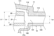
- the dimension La in the axial direction AD of the close air flow path 131 is the dimension in the axial direction AD of the trailing edge 21 b in each blade 21 (that is, the blade height Lb), and the rear of the centrifugal fan 20.
- the dimension of the edge portion 21b in the axial direction AD (that is, the fan height Lf) is set as a reference.
- the fan height Lf is a height obtained by adding the thickness of the shroud 22 and the main plate 23 in the axial direction AD to the blade height Lb.
- the dimension La in the axial direction AD of the close air flow path 131 is the length in the axial direction AD at a position in the discharge air flow path 13 that is closest to the rear edge portion 21b of each blade 21 of the centrifugal fan 20.
- the length in the axial direction AD at the position closest to the rear edge 21b of each blade 21 of the centrifugal fan 20 in the discharge air flow path 13 may be simply referred to as the air flow path height La.
- the dimension La in the axial direction AD is set to be not less than the blade height Lb and not more than the fan height Lf.
- the air flow path height La of the proximity air flow path 131 is not less than the blade height Lb and not more than the fan height. That is, the proximity air channel 131 is set in a range where the dimension La in the axial direction AD satisfies the following formula F1.
- the proximity air flow path 131 is preferably set such that the dimension La in the axial direction AD is closer to the blade height Lb than the fan height Lf. That is, it is preferable to set the proximity air channel 131 in a range in which the dimension La in the axial direction AD satisfies the following formula F2.
- the dimension La in the axial direction AD is substantially equal to the blade height Lb (La ⁇ Lb).
- the centrifugal blower 1 When electric power is supplied to the electric motor 30, the electric motor 30 drives the centrifugal fan 20 to rotate. Thereby, the centrifugal fan 20 rotates around the rotating shaft 20a and sucks air from the one side in the axial direction AD through the air suction port 111a as shown by a thick arrow in FIG. Then, the centrifugal fan 20 blows out the air sucked from the air suction port 111a toward the outside in the radial direction RD.
- FIG. 4 is a cross-sectional view showing a main part of a centrifugal blower as a comparative example of the present embodiment.
- the centrifugal blower as a comparative example has a dimension La in the axial direction AD of the close air flow path 131 that is larger than the fan height Lf.
- the flow path shape of the air flow path formed by the centrifugal fan 20 and the blower case 10 is rapidly expanding.
- an unstable vortex that causes noise is generated on the outlet side of the centrifugal fan 20 (that is, in the vicinity of the rear edge portion 21b).
- the dimension La in the axial direction AD of the close air flow path 131 is set to be not less than the blade height Lb and not more than the fan height Lf.
- the air flow path height La of the proximity air flow path 131 is not less than the blade height Lb and not more than the fan height.
- the axial dimension (that is, the length) of the air flow path adjacent to the centrifugal fan 20 in the blower case 10 is set to the blade height at the trailing edge portion 21b of the blade 21. It is set between Lb and the fan height Lf.
- the air flow path height La of the proximity air flow path 131 is not less than the blade height Lb and not more than the fan height.
- the flow path shape of the air flow path formed by the centrifugal fan 20 and the blower case 10 becomes a flow path shape that does not substantially suddenly expand or contract.
- the centrifugal blower 1 of the present embodiment the air flow path formed by the blower case 10 and the centrifugal fan 20 in the centrifugal blower 1 including the blower case 10 and the centrifugal fan 20 that are opened over the entire circumference.
- the noise generated due to the flow path shape can be suppressed.
- the proximity air flow path 131 is formed by a pair of wall portions (that is, the fan-side outer peripheral portion 113 and the motor-side outer peripheral portion 123) facing the axial direction AD in the blower case 10. According to this, the physique of the site
- Such a configuration is suitable when the centrifugal blower 1 is disposed at a position where the installation space is limited, such as inside a vehicle seat.
- the electric motor 30 is disposed on the back side of the main plate 23. According to this, since the electric motor 30 itself does not become a factor which disturbs the flow of air, generation
- the discharge air flow path 13 has a flow path shape extending along the radial direction RD so that the length in the axial direction AD is almost uniform over the entire area in the radial direction RD. For this reason, the entire region of the discharge air flow path 13 is set between the blade height Lb and the fan height Lf at the trailing edge 21b of the blade 21. According to this, it becomes possible to suppress the generation of noise while suppressing the physique of the centrifugal blower 1.
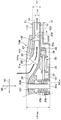
- the present embodiment is different from the first embodiment in that the near air flow path 131A is constituted by the shroud 22 and the main plate 23 of the centrifugal fan 20A.
- the present embodiment description of the same or equivalent parts as in the first embodiment will be omitted or simplified.
- the fan-side step 112 and the motor-side step 122 in the first embodiment are omitted from the blower case 10A of the present embodiment. That is, in the blower case 10A of the present embodiment, the fan-side inner peripheral portion 111 and the fan-side outer peripheral portion 113 are continuously formed, and the motor-side inner peripheral portion 121 and the motor-side outer peripheral portion 123 are continuously connected. Is formed.
- the shroud 22 and the main plate 23 extend outward in the radial direction RD from the rear edge portion 21b of each blade 21.
- the shroud 22 of the present embodiment is provided with a shroud side extending portion 222 that extends toward the outside in the radial direction RD from the rear edge portion 21b of each blade 21.
- the shroud side extension part 222 comprises the 1st extension part extended on the radial direction RD outer side of the rotating shaft 20a rather than the rear edge part 21b of each blade
- the main plate 23 of the present embodiment is provided with a main plate-side extending portion 232 that extends outward in the radial direction RD from the rear edge portion 21b of each blade 21.
- the main plate side extending portion 232 constitutes a second extending portion that extends outward in the radial direction RD of the rotating shaft 20a from the rear edge portion 21b of each blade 21.
- discharge air flow path 13 of this embodiment is comprised by the air flow path in which the whole region including the proximity air flow path 131A is formed between the shroud side extension part 222 and the main plate side extension part 232. Yes.
- the proximity air flow path 131A of the present embodiment is an air flow path that is closer to the rear edge portion 21b of each blade 21 than the air blowing portion 14 in the discharge air flow path 13.
- the dimension La in the axial direction AD is substantially equal to the blade height Lb (La ⁇ Lb).
- the proximity air channel 131A has an air channel height La that is substantially equal to the blade height Lb.
- the proximity air flow path 131 ⁇ / b> A is formed by the extending portions 222 and 232 of the shroud 22 and the main plate 23. According to this, the flow path shape in the proximity air flow path 131A becomes a continuous flow path shape without a break. For this reason, it becomes possible to further suppress noise generated due to the air flow path shape formed by the blower case 10 ⁇ / b> A and the centrifugal fan 20.
- the air discharged from the centrifugal fan 20 through the gap formed between the shroud 22 and the fan cover 11 of the blower case 10 ⁇ / b> A becomes the air suction port of the centrifugal fan 20. Backflow to the 111a side can be suppressed.
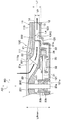
- the present embodiment is different from the above-described embodiments in that the proximity air flow path 131B is configured by the main plate 23 of the centrifugal fan 20B and the fan cover 11 of the blower case 10B.
- description of parts that are the same as or equivalent to those in the above-described embodiments will be omitted or simplified.
- the motor side step 122 in the first embodiment is omitted from the blower case 10 ⁇ / b> B of the present embodiment. That is, the blower case 10 ⁇ / b> B of the present embodiment has the motor side inner peripheral portion 121 and the motor side outer peripheral portion 123 formed continuously.
- the main plate 23 extends outward in the radial direction RD from the rear edge portion 21b of each blade 21.
- the main plate 23 of the present embodiment is provided with a main plate-side extending portion 232 that extends outward in the radial direction RD from the rear edge portion 21b of each blade 21.
- the main plate side extending portion 232 constitutes an extending portion that extends outward in the radial direction RD of the rotating shaft 20a from the rear edge portion 21b of each blade 21.
- the fan cover 11 constitutes a wall portion closer to the shroud 22 than the main plate 23.
- the discharge air flow path 13 of this embodiment is comprised by the air flow path in which the whole region including the proximity air flow path 131B is formed between the fan side outer peripheral part 113 and the main-plate side extension part 232.
- the near air flow path 131 ⁇ / b> B of the present embodiment is an air flow path that is closer to the fan side step 112 than the air blowing section 14 in the discharge air flow path 13.
- the dimension La in the axial direction AD is set to be not less than the blade height Lb and not more than the fan height Lf.
- the air flow path height La of the proximity air flow path 131B is not less than the blade height Lb and not more than the fan height.
- the proximity air flow path 131B is formed by the fan-side outer peripheral portion 113 of the blower case 10B and the main plate-side extending portion 232 of the main plate 23.
- the main plate 23 side in the close air flow path 131B has a continuous flow path shape without a break. For this reason, it becomes possible to further suppress noise generated due to the air flow path shape formed by the blower case 10B and the centrifugal fan 20B.
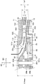
- the fan side step 112 in the first embodiment is omitted from the blower case 10C of the present embodiment. That is, in the blower case 10 ⁇ / b> C of the present embodiment, the fan side inner peripheral portion 111 and the fan side outer peripheral portion 113 are continuously formed.
- the shroud 22 extends outward in the radial direction RD from the rear edge portion 21 b of each blade 21.
- the shroud 22 of the present embodiment is provided with a shroud side extending portion 222 that extends outward in the radial direction RD from the rear edge portion 21 b of each blade 21.
- the shroud side extending portion 222 constitutes an extending portion that extends outward in the radial direction RD of the rotating shaft 20a from the rear edge portion 21b of each blade 21.
- the motor cover 12 constitutes a wall portion closer to the main plate 23 than the shroud 22.
- the discharge air flow path 13 of this embodiment is comprised by the air flow path in which the whole region including the proximity air flow path 131C is formed between the motor side outer peripheral part 123 and the shroud side extension part 222.
- the near air flow path 131 ⁇ / b> C of the present embodiment is an air flow path that is closer to the motor side step portion 122 than the air blowing portion 14 in the discharge air flow path 13.
- the dimension La in the axial direction AD is set to be not less than the blade height Lb and not more than the fan height Lf.
- the air channel height La is not less than the blade height Lb and not more than the fan height.
- the proximity air flow path 131 ⁇ / b> C is formed by the motor-side outer peripheral portion 123 of the blower case 10 ⁇ / b> C and the shroud-side extension portion 222 of the shroud 22. According to this, the shroud 22 side in the close air flow path 131C becomes a continuous flow path shape without a break. For this reason, it becomes possible to further suppress the noise generated due to the air flow path shape formed by the blower case 10C and the centrifugal fan 20C.
- the air discharged from the centrifugal fan 20C via the clearance gap formed between the shroud 22 and the fan cover 11 of the blower case 10C is the air suction port of the centrifugal fan 20. Backflow to the 111a side can be suppressed.
- the fan case 10D of the present embodiment has a shape in which the fan-side outer peripheral portion 113 and the motor-side outer peripheral portion 123 are gradually separated toward the outer side in the radial direction RD. That is, the fan-side outer peripheral portion 113 has a shape in which the position in the axial direction AD gradually moves away from the motor cover 12 toward the outer side in the radial direction RD. Similarly, the motor-side outer peripheral portion 123 has a shape in which the position in the axial direction AD gradually moves away from the fan cover 11 toward the outer side in the radial direction RD.
- the length in the axial direction AD increases toward the downstream side of the air flow.
- the discharge air flow path 13 of the present embodiment has the smallest length in the axial direction AD in the vicinity of the rear edge portion 21 b of each blade 21. Further, the discharge air flow path 13 of the present embodiment has the largest length in the axial direction AD in the vicinity of the air blowing portion 14. Further, in the discharge air flow path 13 of the present embodiment, the length Lc in the axial direction AD near the air blowing portion 14 is set to be equal to or less than the maximum length Lfmax in the axial direction AD of the centrifugal fan 20 (Lc ⁇ Lfmax). ).
- the length of the discharge air flow path 13 in the axial direction AD is increased toward the downstream side of the air flow. According to this, rapid expansion between the outlet side of the discharge air flow path 13 and the discharge target space side from which air is discharged can be suppressed. As a result, it is possible to suppress the generation of noise between the outlet side of the discharge air flow path 13 and the discharge target space side from which air is discharged.
- the length in the axial direction AD of the discharge air flow path 13 is set to be equal to or less than the maximum length in the axial direction AD of the centrifugal fan 20. According to this, it becomes possible to suppress the generation of noise while suppressing the physique of the centrifugal blower 1.
- Such a configuration is suitable, for example, when the centrifugal blower 1 is arranged at a position where the installation space is limited, such as inside a vehicle seat.
- the blower case 10E of the present embodiment has a shape in which the fan-side outer peripheral portion 113 and the motor-side outer peripheral portion 123 are gradually separated toward the outside in the radial direction RD. That is, the fan-side outer peripheral portion 113 has a shape in which the position in the axial direction AD gradually moves away from the motor cover 12 toward the outer side in the radial direction RD. Similarly, the motor-side outer peripheral portion 123 has a shape in which the position in the axial direction AD gradually moves away from the fan cover 11 toward the outer side in the radial direction RD.
- the shroud side extending portion 222 and the main plate side extending portion 232 are gradually moved outward in the radial direction RD, similarly to the fan side outer peripheral portion 113 and the motor side outer peripheral portion 123. It has a shape that leaves. That is, the shroud-side extension part 222 has a shape in which the position in the axial direction AD gradually separates from the motor cover 12 toward the outer side in the radial direction RD, like the fan-side outer peripheral part 113. Further, the main plate side extending portion 232 has a shape in which the position in the axial direction AD gradually separates from the fan cover 11 toward the outside in the radial direction RD, similarly to the motor side outer peripheral portion 123.
- the length in the axial direction AD increases toward the downstream side of the air flow.
- the discharge air flow path 13 of the present embodiment has the smallest length in the axial direction AD in the vicinity of the rear edge portion 21 b of each blade 21. Further, the discharge air flow path 13 of the present embodiment has the largest length in the axial direction AD in the vicinity of the air blowing portion 14. Further, in the discharge air passage 13 of the present embodiment, the length Ld in the axial direction AD near the air blowing portion 14 is set to be equal to or less than the maximum length Lfmax in the axial direction AD of the centrifugal fan 20 (Ld ⁇ Lfmax). ).
- the length in the axial direction AD of the discharge air flow path 13 is set to be equal to or less than the maximum length in the axial direction AD of the centrifugal fan 20 as in the fifth embodiment. For this reason, according to the structure of this embodiment, there exists an effect similar to 5th Embodiment.
- centrifugal blower 1 In each of the above-described embodiments, the example in which the centrifugal blower 1 is applied to a blowing means in a vehicle has been described. However, the present invention is not limited to this.
- the centrifugal blower 1 may be applied to, for example, a blowing unit of a stationary air conditioner used in a home or factory.
- the centrifugal fan 20 may be a radial fan in which the outlet side of the fan faces the radial direction RD.
- the electric motor 30 may adopt an inner rotor type.
- the electric motor 30 may be an AC motor.
- the present invention is not limited to this.
- the electric motor 30 is arranged on the surface side of the main plate 23. Also good.
- the electric motor 30 may be disposed at least partially outside the blower case 10.
- the length of the discharge air flow path 13 in the axial direction AD is increased toward the downstream side of the air flow.
- the length of the discharge air flow path 13 in the axial direction AD may be increased toward the downstream side of the air flow.
- the length of the discharge air passage 13 in the axial direction AD is desirable to be equal to or less than the maximum length of the centrifugal fan 20 in the axial direction AD. It is not limited to. For example, in a part of the discharge air flow path 13, the length in the axial direction AD may be longer than the maximum length in the axial direction AD of the centrifugal fan 20.
Landscapes
- Engineering & Computer Science (AREA)
- Mechanical Engineering (AREA)
- General Engineering & Computer Science (AREA)
- Structures Of Non-Positive Displacement Pumps (AREA)
Abstract
Description
の遠心ファンは、回転軸の周方向に並んで配置される複数枚の羽根、複数枚の羽根における軸方向の一方側を連結するシュラウド、複数枚の羽根における軸方向の他方側を連結すると共に、回転軸に連結される主板を有している。
吐出空気流路は、複数枚の羽根の後縁部に近接する近接空気流路を含んでいる。
近接空気流路は、軸方向の長さが、羽根高さ以上、且つ、ファン高さ以下となっている。
本実施形態に係る遠心式送風機1について、図1~図5を参照して説明する。図2における矢印ADは、後述する遠心ファン20の回転軸20aの軸方向を示している。また、図2における矢印RDは、後述する遠心ファン20の回転軸20aの径方向を示している。このことは、図2以外の図面においても同様である。なお、図2では、図1に示すII-IIに沿って遠心式送風機1を切断した際の断面形状の一部を図示している。
近接空気流路131は、軸方向ADの寸法Laがファン高さLfよりも羽根高さLbに近い寸法に設定することが好ましい。すなわち、近接空気流路131は、軸方向ADの寸法Laが以下の数式F2を満たす範囲に設定することが好ましい。
また、近接空気流路131は、軸方向ADの寸法Laが羽根高さLbと実質的に同等とすることがより一層好ましい(La≒Lb)。
次に、第2実施形態について図6を参照して説明する。本実施形態では、近接空気流路131Aを遠心ファン20Aのシュラウド22および主板23で構成している点が第1実施形態と相違している。本実施形態では、第1実施形態と同様または均等な部分についての説明を省略、または簡略化して説明する。
次に、第3実施形態について図7を参照して説明する。本実施形態では、近接空気流路131Bを遠心ファン20Bの主板23と送風ケース10Bのファンカバー11で構成している点が上述の各実施形態と相違している。本実施形態では、上述の各実施形態と同様または均等な部分についての説明を省略、または簡略化して説明する。
次に、第4実施形態について図8を参照して説明する。本実施形態では、近接空気流路131Cを遠心ファン20Cのシュラウド22と送風ケース10Cのモータカバー12で構成している点が上述の各実施形態と相違している。本実施形態では、上述の各実施形態と同様または均等な部分についての説明を省略、または簡略化して説明する。
次に、第5実施形態について図9を参照して説明する。本実施形態では、吐出空気流路13の流路形状を変更している点が上述の第1実施形態と相違している。本実施形態では、上述の第1実施形態と同様または均等な部分についての説明を省略、または簡略化して説明する。
次に、第6実施形態について図10を参照して説明する。本実施形態では、吐出空気流路13の流路形状を変更している点が上述の第2実施形態と相違している。本実施形態では、上述の第2実施形態と同様または均等な部分についての説明を省略、または簡略化して説明する。
以上、本開示の実施形態について説明したが、本開示は上述の実施形態に限定されるものではなく、適宜変更が可能である。例えば、以下のように種々変形可能である。
Claims (10)
- 空気を送風する遠心式送風機であって、
回転軸(20a)の軸方向の一方側から吸い込んだ空気を前記回転軸の径方向外側に向けて吐出する遠心ファン(20、20A~20C、20E)と、
前記遠心ファンを収容すると共に、前記回転軸を中心とする全周にわたって開口する送風ケース(10、10A~10E)と、を備え、
前記遠心ファンは、前記回転軸の周方向に並んで配置される複数枚の羽根(21)、前記複数枚の羽根における前記軸方向の一方側を連結するシュラウド(22)、前記複数枚の羽根における前記軸方向の他方側を連結すると共に、前記回転軸に連結される主板(23)を有しており、
前記送風ケースの内部には、前記複数枚の羽根の後縁部(21b)よりも空気流れ下流側に前記回転軸の径方向外側に延びる吐出空気流路(13)が形成されており、
前記吐出空気流路は、前記複数枚の羽根の後縁部に近接する近接空気流路(131、131A~131C)を含んでおり、
前記複数枚の羽根の前記後縁部における前記軸方向の長さを羽根高さ(Lb)とし、前記遠心ファンの前記後縁部における前記軸方向の長さをファン高さ(Lf)としたとき、
前記近接空気流路は、前記軸方向の長さ(La)が、前記羽根高さ以上、且つ、前記ファン高さ以下となっている遠心式送風機。 - 空気を送風する遠心式送風機であって、
回転軸(20a)の軸方向の一方側から吸い込んだ空気を前記回転軸の径方向外側に向けて吐出する遠心ファン(20、20A~20C、20E)と、
前記遠心ファンを収容すると共に、前記回転軸を中心とする全周にわたって開口する送風ケース(10、10A~10E)と、を備え、
前記遠心ファンは、前記回転軸の周方向に並んで配置される複数枚の羽根(21)、前記複数枚の羽根における前記軸方向の一方側を連結するシュラウド(22)、前記複数枚の羽根における前記軸方向の他方側を連結すると共に、前記回転軸に連結される主板(23)を有しており、
前記送風ケースの内部には、前記複数枚の羽根の後縁部(21b)よりも空気流れ下流側に前記回転軸の径方向外側に延びる吐出空気流路(13)が形成されており、
前記吐出空気流路は、前記複数枚の羽根の後縁部に近接する近接空気流路(131、131A~131C)を含んでおり、
前記吐出空気流路の前記複数枚の羽根の前記後縁部に最も近い位置における前記軸方向の長さを空気流路高さ(La)とし、前記複数枚の羽根の前記後縁部における前記軸方向の長さを羽根高さ(Lb)とし、前記遠心ファンの前記後縁部における前記軸方向の長さをファン高さ(Lf)としたとき、
前記近接空気流路は、前記空気流路高さが、前記羽根高さ以上、且つ、前記ファン高さ以下となっている遠心式送風機。 - 前記近接空気流路(131)は、前記送風ケースにおける前記軸方向に対向する一対の壁部(113、123)により形成される空気流路である請求項1または2に記載の遠心式送風機。
- 前記シュラウド、および前記主板のうち、一方の部材は、前記複数枚の羽根の前記後縁部よりも前記径方向外側に延出する延出部(222、232)を有しており、
前記送風ケース(10B、10C)は、前記軸方向に対向する一対の壁部(113、123)を有しており、
前記近接空気流路(131B、131C)は、前記延出部、および前記一対の壁部の一方により形成される空気流路である請求項1または2に記載の遠心式送風機。 - 前記一方の部材は、前記主板であり、
前記近接空気流路(131B)は、前記主板における前記延出部(232)、および前記一対の壁部のうち、前記主板よりも前記シュラウドに近い壁部(11)により形成される空気流路である請求項4に記載の遠心式送風機。 - 前記一方の部材は、前記シュラウドであり、
前記近接空気流路(131C)は、前記シュラウドにおける前記延出部(222)、および前記一対の壁部のうち、前記シュラウドよりも前記主板に近い壁部(12)により形成される空気流路である請求項4に記載の遠心式送風機。 - 前記シュラウドは、前記複数枚の羽根の前記後縁部よりも前記径方向外側に延出する第1延出部(222)を有しており、
前記主板は、前記複数枚の羽根の前記後縁部よりも前記径方向外側に延出する第2延出部(232)を有しており、
前記近接空気流路(131A)は、前記第1延出部および前記第2延出部により形成される空気流路である請求項1または2に記載の遠心式送風機。 - 前記遠心ファンを回転駆動する電動機(30)を備え、
前記電動機は、前記主板における前記羽根および前記シュラウドに対向する表面の背面側に配置されている請求項1ないし7のいずれか1つに記載の遠心式送風機。 - 前記吐出空気流路の前記軸方向の長さが前記空気流れ下流側に向かって大きくなっている請求項1ないし8のいずれか1つに記載の遠心式送風機。
- 前記吐出空気流路の前記軸方向の長さは、前記遠心ファンの前記軸方向の最大長さ(Lfmax)以下に設定されている請求項9に記載の遠心式送風機。
Priority Applications (4)
| Application Number | Priority Date | Filing Date | Title |
|---|---|---|---|
| JP2017517867A JPWO2016181821A1 (ja) | 2015-05-14 | 2016-04-26 | 遠心式送風機 |
| US15/572,185 US20180149158A1 (en) | 2015-05-14 | 2016-04-26 | Centrifugal blower |
| CN201680026644.5A CN107614883B (zh) | 2015-05-14 | 2016-04-26 | 离心式送风机 |
| DE112016002180.1T DE112016002180T5 (de) | 2015-05-14 | 2016-04-26 | Zentrifugalgebläse |
Applications Claiming Priority (2)
| Application Number | Priority Date | Filing Date | Title |
|---|---|---|---|
| JP2015099311 | 2015-05-14 | ||
| JP2015-099311 | 2015-05-14 |
Publications (1)
| Publication Number | Publication Date |
|---|---|
| WO2016181821A1 true WO2016181821A1 (ja) | 2016-11-17 |
Family
ID=57248897
Family Applications (1)
| Application Number | Title | Priority Date | Filing Date |
|---|---|---|---|
| PCT/JP2016/063008 Ceased WO2016181821A1 (ja) | 2015-05-14 | 2016-04-26 | 遠心式送風機 |
Country Status (5)
| Country | Link |
|---|---|
| US (1) | US20180149158A1 (ja) |
| JP (1) | JPWO2016181821A1 (ja) |
| CN (1) | CN107614883B (ja) |
| DE (1) | DE112016002180T5 (ja) |
| WO (1) | WO2016181821A1 (ja) |
Cited By (1)
| Publication number | Priority date | Publication date | Assignee | Title |
|---|---|---|---|---|
| US10935049B2 (en) | 2018-04-06 | 2021-03-02 | Denso Corporation | Axial outlet centrifugal-type blower device with noise reducing space |
Families Citing this family (3)
| Publication number | Priority date | Publication date | Assignee | Title |
|---|---|---|---|---|
| JP6827486B2 (ja) * | 2019-02-25 | 2021-02-10 | シナノケンシ株式会社 | 送風機 |
| CN112081762B (zh) * | 2019-06-13 | 2023-01-31 | 苏州凯航电机有限公司 | 一种电风机及清洁设备 |
| CN111878453A (zh) * | 2020-08-06 | 2020-11-03 | 苏州工业园区星德胜电机有限公司 | 一种高功率吸尘器马达风机及其设计方法 |
Citations (5)
| Publication number | Priority date | Publication date | Assignee | Title |
|---|---|---|---|---|
| JPS5596398A (en) * | 1979-01-12 | 1980-07-22 | Toshiba Corp | Diffuser of electric blower for cleaner |
| JPH11182485A (ja) * | 1997-12-16 | 1999-07-06 | Matsushita Electric Ind Co Ltd | 電動送風機及びそれを用いた電気掃除機 |
| JP2012207602A (ja) * | 2011-03-30 | 2012-10-25 | Minebea Co Ltd | 遠心式ファン |
| JP2012251530A (ja) * | 2011-06-07 | 2012-12-20 | Panasonic Corp | 電動送風機とそれを用いた電気掃除機 |
| JP2013076335A (ja) * | 2011-09-29 | 2013-04-25 | Minebea Co Ltd | 遠心式ファン |
Family Cites Families (22)
| Publication number | Priority date | Publication date | Assignee | Title |
|---|---|---|---|---|
| US1914919A (en) * | 1931-10-30 | 1933-06-20 | Allis Chalmers Mfg Co | Centrifugal pump |
| US2144417A (en) * | 1937-01-11 | 1939-01-17 | Claude B Schneible | Sludge pump |
| US3071077A (en) * | 1958-11-25 | 1963-01-01 | Ingersoll Rand Co | Centrifugal pump |
| US3162135A (en) * | 1961-02-20 | 1964-12-22 | Sundstrand Corp | Centrifugal pumps |
| JPS53122906A (en) * | 1977-04-04 | 1978-10-26 | Komatsu Ltd | Impeller of centrifugal compressor |
| US4236871A (en) * | 1978-01-03 | 1980-12-02 | Johnston Brothers (Engineering) Limited | Centrifugal fan impellers with blades secured between plates |
| GB2190429B (en) * | 1986-04-14 | 1990-10-17 | Hitachi Ltd | An electric blower |
| WO1999058857A1 (en) * | 1998-05-13 | 1999-11-18 | Matsushita Electric Industrial Co., Ltd. | Electric blower and vacuum cleaner using it |
| US20050047943A1 (en) * | 2003-08-29 | 2005-03-03 | Jarrah Yousef M. | Compressor surge prevention via distinct blade shapes |
| EP1891335B1 (de) * | 2005-06-06 | 2017-03-29 | Gebr. Becker GmbH | Radialgebläse |
| US8308420B2 (en) * | 2007-08-03 | 2012-11-13 | Hitachi Plant Technologies, Ltd. | Centrifugal compressor, impeller and operating method of the same |
| US8419358B2 (en) * | 2009-06-17 | 2013-04-16 | Sundyne, Llc | Flow output nozzle for centrifugal pump |
| JP5566663B2 (ja) * | 2009-11-09 | 2014-08-06 | 三菱重工業株式会社 | 多翼遠心ファンおよびそれを用いた空気調和機 |
| JP5769978B2 (ja) * | 2011-01-27 | 2015-08-26 | ミネベア株式会社 | 遠心式ファン |
| JP5809859B2 (ja) * | 2011-06-30 | 2015-11-11 | ミネベア株式会社 | 遠心式ファン |
| JP5940266B2 (ja) * | 2011-08-29 | 2016-06-29 | ミネベア株式会社 | 遠心式ファン及び遠心式ファンの製造方法 |
| JP5888494B2 (ja) * | 2011-12-15 | 2016-03-22 | 日本電産株式会社 | 遠心ファン装置 |
| JP5905268B2 (ja) * | 2012-01-17 | 2016-04-20 | 三菱重工業株式会社 | 遠心圧縮機 |
| JP5705945B1 (ja) * | 2013-10-28 | 2015-04-22 | ミネベア株式会社 | 遠心式ファン |
| CN106457964B (zh) * | 2014-06-11 | 2019-04-02 | 松下知识产权经营株式会社 | 温度调节单元、温度调节系统和具备温度调节单元的车辆 |
| JP2016061241A (ja) * | 2014-09-18 | 2016-04-25 | 三菱重工業株式会社 | 遠心羽根車及び遠心圧縮機 |
| JP2016223432A (ja) * | 2015-05-29 | 2016-12-28 | 日本電産株式会社 | インペラ、送風装置、および掃除機 |
-
2016
- 2016-04-26 DE DE112016002180.1T patent/DE112016002180T5/de not_active Ceased
- 2016-04-26 CN CN201680026644.5A patent/CN107614883B/zh not_active Expired - Fee Related
- 2016-04-26 JP JP2017517867A patent/JPWO2016181821A1/ja active Pending
- 2016-04-26 WO PCT/JP2016/063008 patent/WO2016181821A1/ja not_active Ceased
- 2016-04-26 US US15/572,185 patent/US20180149158A1/en not_active Abandoned
Patent Citations (5)
| Publication number | Priority date | Publication date | Assignee | Title |
|---|---|---|---|---|
| JPS5596398A (en) * | 1979-01-12 | 1980-07-22 | Toshiba Corp | Diffuser of electric blower for cleaner |
| JPH11182485A (ja) * | 1997-12-16 | 1999-07-06 | Matsushita Electric Ind Co Ltd | 電動送風機及びそれを用いた電気掃除機 |
| JP2012207602A (ja) * | 2011-03-30 | 2012-10-25 | Minebea Co Ltd | 遠心式ファン |
| JP2012251530A (ja) * | 2011-06-07 | 2012-12-20 | Panasonic Corp | 電動送風機とそれを用いた電気掃除機 |
| JP2013076335A (ja) * | 2011-09-29 | 2013-04-25 | Minebea Co Ltd | 遠心式ファン |
Cited By (1)
| Publication number | Priority date | Publication date | Assignee | Title |
|---|---|---|---|---|
| US10935049B2 (en) | 2018-04-06 | 2021-03-02 | Denso Corporation | Axial outlet centrifugal-type blower device with noise reducing space |
Also Published As
| Publication number | Publication date |
|---|---|
| US20180149158A1 (en) | 2018-05-31 |
| CN107614883B (zh) | 2020-01-14 |
| JPWO2016181821A1 (ja) | 2017-10-05 |
| CN107614883A (zh) | 2018-01-19 |
| DE112016002180T5 (de) | 2018-01-25 |
Similar Documents
| Publication | Publication Date | Title |
|---|---|---|
| JP5940266B2 (ja) | 遠心式ファン及び遠心式ファンの製造方法 | |
| JP5131093B2 (ja) | 遠心式送風機 | |
| EP1707822B1 (en) | Centrifugal fan | |
| JP5256184B2 (ja) | 二重反転式軸流送風機 | |
| US20150118037A1 (en) | Centrifugal fan | |
| WO2011007467A1 (ja) | インペラおよび回転機械 | |
| US11332052B2 (en) | Centrifugal blower device | |
| WO2016181821A1 (ja) | 遠心式送風機 | |
| US20190390676A1 (en) | Centrifugal blower device | |
| WO2016170831A1 (ja) | 遠心式送風機 | |
| JP6131770B2 (ja) | 送風機 | |
| JP2010124534A (ja) | 電動機用斜流ファンと該斜流ファンを備えた電動機 | |
| EP3505769B1 (en) | Multiblade centrifugal fan | |
| WO2016117374A1 (ja) | 送風機 | |
| JP2017122403A (ja) | 渦流ブロワ | |
| JP6760376B2 (ja) | 遠心式送風機 | |
| JP4729906B2 (ja) | 遠心送風機 | |
| WO2020017161A1 (ja) | 電動コンプレッサ | |
| JP6297467B2 (ja) | 遠心ファン | |
| JP4395539B1 (ja) | 多翼遠心ファンおよび車両用空調装置 | |
| JP6588999B2 (ja) | 遠心式ファン | |
| JP2021099073A (ja) | 多翼ファン | |
| US20250257739A1 (en) | Compact vane-axial fan with modular components | |
| EP4317703A1 (en) | Electric blower | |
| CN113958536B (zh) | 离心压缩机 |
Legal Events
| Date | Code | Title | Description |
|---|---|---|---|
| 121 | Ep: the epo has been informed by wipo that ep was designated in this application |
Ref document number: 16792546 Country of ref document: EP Kind code of ref document: A1 |
|
| ENP | Entry into the national phase |
Ref document number: 2017517867 Country of ref document: JP Kind code of ref document: A |
|
| WWE | Wipo information: entry into national phase |
Ref document number: 15572185 Country of ref document: US |
|
| WWE | Wipo information: entry into national phase |
Ref document number: 112016002180 Country of ref document: DE |
|
| 122 | Ep: pct application non-entry in european phase |
Ref document number: 16792546 Country of ref document: EP Kind code of ref document: A1 |