WO2016175221A1 - 車両制御装置 - Google Patents
車両制御装置 Download PDFInfo
- Publication number
- WO2016175221A1 WO2016175221A1 PCT/JP2016/063134 JP2016063134W WO2016175221A1 WO 2016175221 A1 WO2016175221 A1 WO 2016175221A1 JP 2016063134 W JP2016063134 W JP 2016063134W WO 2016175221 A1 WO2016175221 A1 WO 2016175221A1
- Authority
- WO
- WIPO (PCT)
- Prior art keywords
- clutch
- engine
- touch point
- control device
- vehicle
- Prior art date
- Legal status (The legal status is an assumption and is not a legal conclusion. Google has not performed a legal analysis and makes no representation as to the accuracy of the status listed.)
- Ceased
Links
Images



Classifications
-
- B—PERFORMING OPERATIONS; TRANSPORTING
- B60—VEHICLES IN GENERAL
- B60K—ARRANGEMENT OR MOUNTING OF PROPULSION UNITS OR OF TRANSMISSIONS IN VEHICLES; ARRANGEMENT OR MOUNTING OF PLURAL DIVERSE PRIME-MOVERS IN VEHICLES; AUXILIARY DRIVES FOR VEHICLES; INSTRUMENTATION OR DASHBOARDS FOR VEHICLES; ARRANGEMENTS IN CONNECTION WITH COOLING, AIR INTAKE, GAS EXHAUST OR FUEL SUPPLY OF PROPULSION UNITS IN VEHICLES
- B60K6/00—Arrangement or mounting of plural diverse prime-movers for mutual or common propulsion, e.g. hybrid propulsion systems comprising electric motors and internal combustion engines
- B60K6/20—Arrangement or mounting of plural diverse prime-movers for mutual or common propulsion, e.g. hybrid propulsion systems comprising electric motors and internal combustion engines the prime-movers consisting of electric motors and internal combustion engines, e.g. HEVs
- B60K6/42—Arrangement or mounting of plural diverse prime-movers for mutual or common propulsion, e.g. hybrid propulsion systems comprising electric motors and internal combustion engines the prime-movers consisting of electric motors and internal combustion engines, e.g. HEVs characterised by the architecture of the hybrid electric vehicle
- B60K6/48—Parallel type
-
- B—PERFORMING OPERATIONS; TRANSPORTING
- B60—VEHICLES IN GENERAL
- B60K—ARRANGEMENT OR MOUNTING OF PROPULSION UNITS OR OF TRANSMISSIONS IN VEHICLES; ARRANGEMENT OR MOUNTING OF PLURAL DIVERSE PRIME-MOVERS IN VEHICLES; AUXILIARY DRIVES FOR VEHICLES; INSTRUMENTATION OR DASHBOARDS FOR VEHICLES; ARRANGEMENTS IN CONNECTION WITH COOLING, AIR INTAKE, GAS EXHAUST OR FUEL SUPPLY OF PROPULSION UNITS IN VEHICLES
- B60K6/00—Arrangement or mounting of plural diverse prime-movers for mutual or common propulsion, e.g. hybrid propulsion systems comprising electric motors and internal combustion engines
- B60K6/20—Arrangement or mounting of plural diverse prime-movers for mutual or common propulsion, e.g. hybrid propulsion systems comprising electric motors and internal combustion engines the prime-movers consisting of electric motors and internal combustion engines, e.g. HEVs
- B60K6/50—Architecture of the driveline characterised by arrangement or kind of transmission units
- B60K6/54—Transmission for changing ratio
- B60K6/547—Transmission for changing ratio the transmission being a stepped gearing
-
- B—PERFORMING OPERATIONS; TRANSPORTING
- B60—VEHICLES IN GENERAL
- B60L—PROPULSION OF ELECTRICALLY-PROPELLED VEHICLES; SUPPLYING ELECTRIC POWER FOR AUXILIARY EQUIPMENT OF ELECTRICALLY-PROPELLED VEHICLES; ELECTRODYNAMIC BRAKE SYSTEMS FOR VEHICLES IN GENERAL; MAGNETIC SUSPENSION OR LEVITATION FOR VEHICLES; MONITORING OPERATING VARIABLES OF ELECTRICALLY-PROPELLED VEHICLES; ELECTRIC SAFETY DEVICES FOR ELECTRICALLY-PROPELLED VEHICLES
- B60L50/00—Electric propulsion with power supplied within the vehicle
- B60L50/10—Electric propulsion with power supplied within the vehicle using propulsion power supplied by engine-driven generators, e.g. generators driven by combustion engines
- B60L50/16—Electric propulsion with power supplied within the vehicle using propulsion power supplied by engine-driven generators, e.g. generators driven by combustion engines with provision for separate direct mechanical propulsion
-
- B—PERFORMING OPERATIONS; TRANSPORTING
- B60—VEHICLES IN GENERAL
- B60W—CONJOINT CONTROL OF VEHICLE SUB-UNITS OF DIFFERENT TYPE OR DIFFERENT FUNCTION; CONTROL SYSTEMS SPECIALLY ADAPTED FOR HYBRID VEHICLES; ROAD VEHICLE DRIVE CONTROL SYSTEMS FOR PURPOSES NOT RELATED TO THE CONTROL OF A PARTICULAR SUB-UNIT
- B60W10/00—Conjoint control of vehicle sub-units of different type or different function
- B60W10/02—Conjoint control of vehicle sub-units of different type or different function including control of driveline clutches
-
- B—PERFORMING OPERATIONS; TRANSPORTING
- B60—VEHICLES IN GENERAL
- B60W—CONJOINT CONTROL OF VEHICLE SUB-UNITS OF DIFFERENT TYPE OR DIFFERENT FUNCTION; CONTROL SYSTEMS SPECIALLY ADAPTED FOR HYBRID VEHICLES; ROAD VEHICLE DRIVE CONTROL SYSTEMS FOR PURPOSES NOT RELATED TO THE CONTROL OF A PARTICULAR SUB-UNIT
- B60W20/00—Control systems specially adapted for hybrid vehicles
-
- F—MECHANICAL ENGINEERING; LIGHTING; HEATING; WEAPONS; BLASTING
- F16—ENGINEERING ELEMENTS AND UNITS; GENERAL MEASURES FOR PRODUCING AND MAINTAINING EFFECTIVE FUNCTIONING OF MACHINES OR INSTALLATIONS; THERMAL INSULATION IN GENERAL
- F16D—COUPLINGS FOR TRANSMITTING ROTATION; CLUTCHES; BRAKES
- F16D25/00—Fluid-actuated clutches
- F16D25/12—Details not specific to one of the before-mentioned types
-
- Y—GENERAL TAGGING OF NEW TECHNOLOGICAL DEVELOPMENTS; GENERAL TAGGING OF CROSS-SECTIONAL TECHNOLOGIES SPANNING OVER SEVERAL SECTIONS OF THE IPC; TECHNICAL SUBJECTS COVERED BY FORMER USPC CROSS-REFERENCE ART COLLECTIONS [XRACs] AND DIGESTS
- Y02—TECHNOLOGIES OR APPLICATIONS FOR MITIGATION OR ADAPTATION AGAINST CLIMATE CHANGE
- Y02T—CLIMATE CHANGE MITIGATION TECHNOLOGIES RELATED TO TRANSPORTATION
- Y02T10/00—Road transport of goods or passengers
- Y02T10/60—Other road transportation technologies with climate change mitigation effect
- Y02T10/62—Hybrid vehicles
Definitions
- the present invention relates to a vehicle control apparatus for a hybrid vehicle including a transmission capable of transmitting a motor driving force to an output shaft, and in particular, a vehicle having a learning function of a clutch torque transmission start point (hereinafter referred to as a touch point).
- the present invention relates to a control device.
- a device for learning about a clutch has been proposed in order to improve the accuracy of clutch control in a hybrid vehicle.
- learning control regarding the degree of clutch engagement is performed in a state where an internal combustion engine (for example, an engine) is operated and a transmission is in a neutral state (see, for example, Patent Document 1).
- the engine is started (starter is started), and the clutch is gradually moved to the coupling side when the input rotational speed of the transmission is zero. Then, the clutch position when the input rotational speed reaches a predetermined rotational speed is learned as a touch point. After the operation for learning the touch point is completed, the clutch is returned to the disengagement side, the gear is shifted to the traveling gear, the clutch is engaged, and the torque of the engine and the motor is changed (one torque). The shortage is compensated with the other torque), and the vehicle shifts to acceleration running.
- the conventional device requires a special operation for learning the touch point. For this reason, the speed and response of the control operation when learning the touch point is delayed compared with the case where the touch point is not learned, which affects the behavior and drivability of the vehicle. Further, in the conventional device, in order to learn the touch point, it is necessary to satisfy the condition that the engine speed is constant (idle speed or higher) and the input speed is zero. Therefore, when learning the touch point during EV traveling (during traveling by the motor driving force), a waiting time is required until the gear of the transmission is once pulled out to neutral and the input rotational speed becomes zero.
- An object of the present invention is to provide a vehicle control device capable of learning touch points without affecting drivability.
- One aspect of the present invention is a vehicle control device, which is a control device for a hybrid vehicle including a transmission capable of transmitting a motor driving force to an output shaft, in response to an engine start request.
- a clutch control unit that moves the clutch to the coupling side, and the acceleration of the vehicle is kept constant when the accelerator opening of the vehicle is constant and the road surface being traveled has a constant slope.
- a rotational speed control unit that performs rotational speed control, and a touch point that determines that the amount of change in motor torque that is greater than a predetermined determination value when the clutch is moved to the engagement side is a touch point of the clutch. And a determination unit.
- a vehicle control device which is a vehicle control device for a hybrid vehicle including a transmission capable of transmitting a motor driving force to an output shaft, in response to an engine start request.
- a clutch control unit that moves the clutch to the coupling side, an engine speed determination unit that determines whether or not the engine speed exceeds a predetermined reference value, and the engine speed that satisfies the reference value.
- the clutch position is disengaged and the shift position is set to the neutral position, the amount of change in the rotational speed of the input shaft becomes greater than a predetermined judgment value when the clutch is moved to the engagement side.
- a touch point determination unit that determines that the clutch is a touch point of the clutch.
- Still another aspect of the present invention is a vehicle control device, which is a vehicle control device for a hybrid vehicle including a transmission capable of transmitting a motor driving force to an output shaft, and is provided with an engine start request.
- a clutch control unit that moves the clutch to the engagement side
- a storage unit that stores a design value of a stroke amount of the clutch when the engine speed exceeds a predetermined reference value, and the clutch on the engagement side
- detecting the clutch stroke amount when the engine speed exceeds the reference value and determining the difference between the detected stroke amount and the design value as the clutch touch point.
- a touch point determination unit It has.
- FIG. 1 is a configuration diagram of a hybrid vehicle according to the first embodiment.
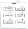
- FIG. 2 is a block diagram showing the configuration of the control device according to the first embodiment of the present invention.
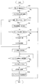
- FIG. 3 is a flowchart for explaining the operation of the control device according to the first embodiment.
- FIG. 4 is a time chart for explaining the operation of the control device according to the first embodiment.
- FIG. 5 is a block diagram showing the configuration of the control device according to the second embodiment of the present invention.
- FIG. 6 is a flowchart for explaining the operation of the control device according to the second embodiment.
- FIG. 7 is a time chart for explaining the operation of the control device according to the second embodiment.
- FIG. 8 is a block diagram showing the configuration of the control device according to the third embodiment of the present invention.
- FIG. 9 is a flowchart for explaining the operation of the control device according to the third embodiment.
- FIG. 10 is a time chart for explaining the operation of the control device according to the third embodiment.
- a vehicle control device is a control device for a hybrid vehicle including a transmission capable of transmitting a motor driving force to an output shaft.
- the clutch control moves a clutch to a coupling side in response to an engine start request.
- a rotation speed control unit that performs a rotation speed control so as to keep the acceleration of the vehicle constant when the accelerator opening of the vehicle is constant and the road surface being traveled has a constant slope,
- a touch point determination unit that determines that a point at which the amount of change in motor torque is greater than a predetermined determination value when the clutch is moved to the engagement side is a touch point of the clutch.
- control device of the present invention may include a gradient determination unit that acquires information on the acceleration of the vehicle and determines whether or not the traveling road surface has a constant gradient.
- This configuration makes it possible to appropriately determine whether or not the traveling road surface has a constant gradient based on the vehicle acceleration information.
- the clutch control unit may move the clutch to the coupling side when there is a request to start the engine when switching from running by motor drive to hybrid running.
- This configuration eliminates the need for special operations for touch point learning, which are required for pushing the engine. Therefore, there is no influence on vehicle behavior and drivability.
- a control device of the present invention is a control device for a hybrid vehicle including a transmission capable of transmitting a motor driving force to an output shaft, and a clutch control unit that moves a clutch to a coupling side in response to an engine start request
- An engine speed determination unit that determines whether or not the engine speed exceeds a predetermined reference value; and after the engine speed exceeds the reference value, the clutch position is disengaged and the shift position is set.
- Touch point determination that determines the point at which the amount of change in the rotational speed of the input shaft is greater than a predetermined determination value when the clutch is moved to the coupling side in the neutral position as the touch point of the clutch And a section.
- the control device of the present invention further includes an input shaft rotational speed determination unit that determines whether or not the rotational speed of the input shaft is higher than the rotational speed of the engine, and the clutch control unit includes the rotational speed of the input shaft. When the engine speed is higher than the engine speed, the clutch may be moved to the coupling side in response to the pushing request.
- control device of the present invention may include a touch point correction unit that corrects the touch point determined by the touch point determination unit based on the temperature characteristic information of the clutch.
- This configuration makes it possible to appropriately correct the touch point in consideration of the temperature characteristics of the clutch (temperature changes in the clutch components).
- the clutch control unit moves the clutch to the coupling side when there is a request to start the engine when the rotational speed of the input shaft is higher than the rotational speed of the engine. May be.
- This configuration eliminates the need for special operations for touch point learning, which are required for pushing the engine. Therefore, there is no influence on vehicle behavior and drivability.
- a control device of the present invention is a control device for a hybrid vehicle including a transmission capable of transmitting a motor driving force to an output shaft, and a clutch control unit that moves a clutch to a coupling side in response to an engine start request
- a storage unit that stores a design value of a stroke amount of the clutch when the engine speed exceeds a predetermined reference value; and when the clutch is moved to the coupling side, the engine speed is
- a touch point determination unit that detects a stroke amount of the clutch when the reference value is exceeded, and determines a difference between the detected stroke amount and the design value as a touch point of the clutch;
- the design value of the stroke amount of the clutch when the engine speed exceeds the predetermined reference value on the engine-side clutch disc for example, the state where the transmission-side clutch disc is sufficiently in contact with the engine-side clutch disc.
- the torque is applied from the transmission side
- the input torque when the engine speed exceeds a predetermined reference value is converted into the clutch stroke amount) and stored in the storage unit.
- the clutch stroke amount when the engine speed exceeds the reference value is detected, and the detected stroke amount and the design value are detected. Is determined as the clutch touch point.
- the present invention as described above, it is possible to learn a touch point in a control operation (normal operation) required for pushing the engine.
- the conventional operation for learning the touch point (a special operation that is not necessary originally) becomes unnecessary. Therefore, there is no influence on vehicle behavior and drivability by learning touch points.
- the touch point can be learned during normal operation when the engine is started (for example, when the engine is pushed).
- FIG. 1 is a configuration diagram of a hybrid vehicle according to the present embodiment.
- the hybrid vehicle 1 includes an engine 2 and a motor generator 3, and one or both of them are used as a driving force source for the wheels 4.
- An automatic transmission 6 is connected to the engine 2 via a clutch 5, and an output from the automatic transmission 6 is distributed and transmitted to the left and right wheels 4 via a differential gear device (diff 7).
- the motor generator 3 is also connected to the automatic transmission 6 via a second clutch 8.
- the motor generator 3 is electrically connected to a power storage device (battery) via an inverter.
- Engine 2 is a device that is driven by combustion of fuel inside the engine to extract power, and for example, various known engines such as a gasoline engine and a diesel engine can be used.
- the motor generator 3 has a rotor and a stator (not shown), functions as a motor (electric motor) that generates power upon receiving power supply, and a generator that generates power upon receiving power supply. It has a function as a (generator).
- the motor generator 3 receives power supplied from the power storage device and performs power running, and supplies the power storage device with power generated by the torque output from the engine 2 or the inertial force of the vehicle to store the power storage device.
- a capacitor or the like can be used in addition to the battery.
- the clutch 5 is a friction coupling device provided between the engine 2 and the automatic transmission 6 and capable of switching between transmission and disconnection of the driving force between the engine 2 and the automatic transmission 6.
- the second clutch 8 is a friction coupling device provided between the motor generator 3 and the automatic transmission 6 and capable of switching between transmission and interruption of driving force between the motor generator 3 and the automatic transmission 6. is there.
- the clutch 5 and the second clutch 8 are provided between the engine 2 and the motor generator 3, and a frictional joint that can switch between transmission and interruption of driving force between the engine 2 and the motor generator 3. It can be said that it constitutes a device.
- the clutch 5 can continuously control increase / decrease in its transmission torque capacity by controlling the supply hydraulic pressure.
- the automatic transmission 6 is configured to be able to transmit the motor driving force of the motor generator 3 to the output shaft 20.
- control device 9 has a function of controlling the clutch 5, a function of controlling the automatic transmission 6, a function of controlling the engine 2, and a function of controlling the motor generator 3 (including an inverter and a battery). Yes.
- FIG. 2 is a block diagram for explaining the configuration of the control device 9.
- the control device 9 includes a clutch control unit 10 for controlling the operation of the clutch 5, a rotation speed control unit 11 for controlling the rotation speed of the engine 2, and touch points of the clutch 5.
- a touch point determination unit 12 for determination is provided.
- the control device 9 includes an accelerator opening degree determination unit 13, a gradient determination unit 14, and a touch point correction unit 15 as a configuration for determining a touch point.
- the accelerator opening degree determination unit 13 acquires information on the accelerator opening degree (for example, an accelerator signal) from the vehicle 1 and determines whether or not the accelerator opening degree is constant. Further, the gradient determination unit 14 acquires acceleration information from the vehicle 1 and information on the acceleration (for example, acceleration measured by an acceleration sensor, acceleration calculated from a change in vehicle speed measured by a vehicle speed sensor, etc.). Based on the above, it is determined whether or not the traveling road surface has a constant gradient (for example, flat).
- the clutch control unit 10 performs control to move the clutch 5 to the engagement side when there is a request to push the engine 2 when switching from EV traveling (travel by motor drive) to HV traveling (hybrid traveling). At this time, the rotation speed control unit 11 controls the rotation speed so as to keep the acceleration of the vehicle constant when the accelerator opening of the vehicle is constant and the road surface being traveled has a constant gradient (for example, flat). I do.
- the touch point determination unit 12 determines the clutch position at which the amount of change in motor torque is greater than a predetermined determination value as the touch point of the clutch 5 when the clutch 5 is moved to the coupling side.
- the touch point correction unit 15 corrects the touch point determined by the touch point determination unit 12 based on the temperature characteristic information (information obtained in advance) of the touch point. Since the torque (stored in the control device 9) required until the engine starts to rotate varies depending on the engine temperature (for example, determined from the water temperature or the like), the touch point correction unit 15 uses, for example, the temperature as an argument. Use the map value
- the control device 9 includes an arithmetic processing device such as a CPU as a core member, and reads out data from a RAM (random access memory) configured to be able to read and write data from the arithmetic processing device and the arithmetic processing device. It has a storage device such as a ROM (Read Only Memory) that can be configured (not shown).
- the clutch control unit 10, the rotational speed control unit 11, the touch point determination unit 12, the accelerator opening degree are achieved by software (program) stored in the ROM or the like, hardware such as a separately provided arithmetic circuit, or both.
- Each functional unit such as the determination unit 13, the gradient determination unit 14, and the touch point correction unit 15 is configured. Each of these functional units is configured to exchange information with each other.
- control device 9 configured as described above will be described with reference to the drawings.
- touch point learning which is a characteristic operation of the present invention will be described.
- FIG. 3 is a flowchart for explaining the operation of the control device 9, and FIG. 4 is a time chart.
- an engine start request (pushing request) is issued from a control device (not shown) other than the control device 9.
- the control device 9 receives this required value (S1).
- the clutch 5 is moved to the coupling side in order to crank the engine 2 (S2).
- the control of the engine 2 is switched from torque control to rotational speed control. (S4). That is, when the driver is driving the vehicle 1 with a constant accelerator, rotation speed control (feedback control) is performed to increase the motor torque so that the vehicle speed is not reduced by the engine load.
- rotation speed control feedback control
- the control of the engine 2 is switched from the rotational speed control to the torque control (S8). That is, torque control (feed forward control) is performed so that the sum of the clutch transmission torque and the motor torque becomes the driver request torque.
- the clutch 5 is moved to the disengaged position at time t5 (S10).
- the determination value 2 is the number of revolutions at which the engine can be started (more than the number of revolutions that can be driven independently).
- the determination value 2 is set to 300 to 800 rpm, for example.
- learning of touch points is performed when the engine 2 is pushed.
- the rotational speed control is performed so as to keep the acceleration of the vehicle 1 constant.
- the clutch 5 is moved to the joining side in response to a request to push the engine 2, the point at which the amount of change in the motor torque becomes larger than a predetermined determination value is determined as the touch point of the clutch 5.
- the present embodiment it is possible to learn a touch point in a control operation (normal operation) required for pushing the engine 2.
- the conventional operation for learning the touch point (a special operation that is not necessary originally) becomes unnecessary. Therefore, there is no influence on the behavior and drivability of the vehicle 1 depending on whether or not the touch point is learned.
- the present embodiment based on the acceleration information of the vehicle 1, it can be appropriately determined whether or not the road surface being traveled has a constant slope. Furthermore, in the present embodiment, it is possible to appropriately correct the touch point in consideration of the temperature characteristic of the touch point (temperature change of the components of the clutch 5).
- FIG. 5 is a block diagram for explaining the configuration of the control device 9 of the present embodiment.
- the control device 9 includes a clutch control unit 10 for controlling the operation of the clutch 5 and a touch point determination unit 12 for determining a touch point of the clutch 5.
- the control device 9 includes an engine speed determination unit 16, an input shaft speed determination unit 17, and a touch point correction unit 15 as a configuration for touch point determination.
- the engine speed determination unit 16 determines whether the speed of the engine 2 exceeds a predetermined reference value. Further, the input shaft rotation speed determination unit 17 determines whether or not the rotation speed of the input shaft is higher than the rotation speed of the engine 2. When the rotational speed of the input shaft is higher than the rotational speed of the engine 2, the clutch control unit 10 moves the clutch 5 to the coupling side in response to a request for pushing the engine 2.
- the touch point determination unit 12 moves the clutch 5 to the engagement side with the clutch position set to the disengaged position and the shift position set to the neutral position.
- the point (clutch position) at which the amount of change in the rotational speed of the input shaft is greater than a predetermined determination value is determined as the touch point of the clutch 5.
- control device 9 of the second embodiment configured as described above will be described with reference to the drawings.
- touch point learning which is a characteristic operation of the present invention will be described.
- FIG. 6 is a flowchart for explaining the operation of the control device 9 according to the second embodiment
- FIG. 7 is a time chart.
- an engine start request (pushing request) is issued from a control device (not shown) other than the control device 9.
- the control device 9 receives this required value (S20).
- the clutch 5 is moved to the coupling side in order to crank the engine 2 (S21).
- the clutch 5 is started to move to the disengagement side, and the shift of the automatic transmission 6 is started to move to the neutral position.
- the shift completes the movement to the neutral position at time t3, and the clutch 5 completes the movement to the disengaged position at time t4 (S23).
- the determination value 1 is the number of rotations at which the engine can be started (more than the number of rotations that can be driven independently). Then, the engine 2 is fired, and after the completion of the explosion determination, the clutch 5 is moved to the joining side at a constant speed at time t5 (S24).
- learning of touch points is performed when the engine 2 is pushed.
- the clutch 5 is moved to the engagement side in response to a push request of the engine 2, and when the rotational speed of the engine 2 exceeds a predetermined reference value, the clutch position is set to the disengaged position and the shift position is set to the neutral position. . Then, when the clutch 5 is moved to the joining side in this state, the point at which the amount of change in the rotational speed of the input shaft becomes greater than a predetermined determination value is determined as the touch point of the clutch 5.
- the engine 2 when the rotation speed of the input shaft is higher than the rotation speed of the engine 2, the engine 2 is appropriately pushed, and at that time (when the engine 2 is pushed), the touch point is also learned. Done.
- FIG. 8 is a block diagram for explaining the configuration of the control device 9 of the present embodiment.
- the control device 9 includes a clutch control unit 10 for controlling the operation of the clutch 5 and a touch point determination unit 12 for determining a touch point of the clutch 5.
- the control device 9 includes a storage unit 18 and a stroke amount detection unit 19 as a configuration for determining a touch point.
- the storage unit 18 stores a design value (a value obtained in advance) of the stroke amount of the clutch 5 when the rotational speed of the engine 2 exceeds a predetermined reference value.
- the stroke amount detector 19 has a function of detecting the stroke amount (clutch position) of the clutch 5.
- the touch point determination unit 12 detects the stroke amount of the clutch 5 when the rotational speed of the engine 2 exceeds a predetermined reference value when the clutch 5 is moved to the joining side, and the detected stroke amount And the design value is determined as the touch point of the clutch 5.
- control device 9 of the third embodiment configured as described above will be described with reference to the drawings.
- touch point learning which is a characteristic operation of the present invention will be described.
- FIG. 9 is a flowchart for explaining the operation of the control device 9 according to the third embodiment
- FIG. 10 is a time chart.
- an engine start request (pushing request) is issued from a control device (not shown) other than the control device 9.
- the control device 9 receives this required value.
- S40 request to push the engine 2
- S41 information on the rotational speed of the engine 2
- S42 time t1
- the clutch 5 is moved to the coupling side in order to crank the engine 2 ( S42).
- the rotational speed of the engine 2 is determined whether or not the rotational speed of the engine 2 has exceeded a predetermined determination value 2 at time t3 (S45).
- the determination value 2 is the number of revolutions at which the engine can be started (more than the number of revolutions that can be driven independently).
- the clutch 5 is moved to the disengaged position, and the shift is set to the neutral position at time t4 (S46). Then, at time t6, a shift to a predetermined shift stage is performed (S47). After the shift is completed, the clutch 5 is engaged at time t7 to t8 and the vehicle is accelerated with engine torque (S48).
- control device of the third embodiment the same operational effects as the first embodiment are exhibited.
- learning of touch points is performed when the engine 2 is pushed.
- the design value of the stroke amount of the clutch 5 when the rotational speed of the engine 2 exceeds a predetermined reference value is stored in the storage unit. Then, when the clutch 5 is moved to the coupling side in response to a request to push the engine 2, the stroke amount of the clutch 5 when the rotational speed of the engine 2 exceeds the reference value is detected, and the detected stroke amount And the design value is determined as the touch point of the clutch 5.
- control device has an effect of being able to learn touch points during normal operation, and is useful for use in a clutch control system for a hybrid vehicle.
Landscapes
- Engineering & Computer Science (AREA)
- Mechanical Engineering (AREA)
- Transportation (AREA)
- Chemical & Material Sciences (AREA)
- Combustion & Propulsion (AREA)
- General Engineering & Computer Science (AREA)
- Automation & Control Theory (AREA)
- Power Engineering (AREA)
- Hybrid Electric Vehicles (AREA)
- Hydraulic Clutches, Magnetic Clutches, Fluid Clutches, And Fluid Joints (AREA)
- Electric Propulsion And Braking For Vehicles (AREA)
Abstract
車両制御装置は、モータ駆動力を出力軸(20)に伝達可能な変速機(6)を備えるハイブリッド車両用の制御装置(9)である。この車両制御装置(9)は、エンジンの始動要求に応じて、クラッチ(5)を継合側に移動させるクラッチ制御部(10)と、車両のアクセル開度が一定であり、かつ、走行中の路面が一定勾配である場合に、車両の加速度を一定に保つような回転数制御を行う回転数制御部(11)と、クラッチ(5)を継合側に移動させたときに、モータトルクの変化量が所定の判定値より大きくなる点を、クラッチのタッチ点と判定するタッチ点判定部(12)を備えている。
Description
本発明は、モータ駆動力を出力軸に伝達可能な変速機を備えたハイブリッド車両の車両制御装置に関し、特に、クラッチのトルク伝達開始点(以下、タッチ点と称す)の学習機能を備えた車両制御装置に関する。
従来から、ハイブリッド車両においてクラッチ制御の精度を向上させるために、クラッチに関する学習をする装置が提案されている。例えば、従来の装置では、内燃機関(例えば、エンジン)を運転させ、変速機をニュートラルにした状態で、クラッチの継合度合いに関する学習制御を行う(例えば特許文献1参照)。
具体的には、エンジンを始動(スタータを始動)させて、変速機のインプット回転数がゼロのときに、クラッチを継合側に徐々に移動させる。そして、インプット回転数が所定の回転数になったときのクラッチ位置をタッチ点として学習する。このようなタッチ点の学習のための動作が終了した後、クラッチを断側に戻して、走行ギヤに変速した後、クラッチを継合させて、エンジンとモータのトルクの掛けかえ(一方のトルク不足分を他方のトルクで補う)を行って、加速走行へ移行する。
しかしながら、従来の装置においては、タッチ点の学習のための特別な動作が必要である。そのため、タッチ点の学習をしない場合に比べて、タッチ点の学習をする場合の制御動作の速度や応答に遅れが生じ、車両の挙動やドライバビリティに影響を及ぼす。また、従来の装置では、タッチ点の学習をするためには、エンジン回転数が一定(アイドル回転数以上)であり、かつ、インプット回転数がゼロであるという条件を満たす必要がある。そのため、EV走行中(モータ駆動力による走行中)にタッチ点を学習する場合は、一旦変速機のギヤをニュートラルに抜き、インプット回転数がゼロになるまでの待ち時間が必要になる。
本発明は、上記背景の下でなされたものである。本発明の目的は、ドライバビリティに影響を与えることなくタッチ点の学習をすることのできる車両制御装置を提供することにある。
本発明の一の態様は、車両制御装置であり、この車両制御装置は、モータ駆動力を出力軸に伝達可能な変速機を備えるハイブリッド車両用の制御装置であって、エンジンの始動要求に応じて、クラッチを継合側に移動させるクラッチ制御部と、前記車両のアクセル開度が一定であり、かつ、走行中の路面が一定勾配である場合に、前記車両の加速度を一定に保つような回転数制御を行う回転数制御部と、前記クラッチを継合側に移動させたときに、モータトルクの変化量が所定の判定値より大きくなる点を、前記クラッチのタッチ点と判定するタッチ点判定部と、を備えている。
本発明の他の態様は、車両制御装置であり、この車両制御装置は、モータ駆動力を出力軸に伝達可能な変速機を備えるハイブリッド車両の車両制御装置であって、エンジンの始動要求に応じて、クラッチを継合側に移動させるクラッチ制御部と、前記エンジンの回転数が所定の基準値を超えたか否かを判定するエンジン回転数判定部と、前記エンジンの回転数が前記基準値を超えた後、クラッチ位置を断位置かつシフト位置をニュートラル位置にした状態で、前記クラッチを継合側に移動させたときに、入力軸の回転数の変化量が所定の判定値より大きくなる点を、前記クラッチのタッチ点と判定するタッチ点判定部と、を備えている。
本発明のさらに他の態様は、車両制御装置であり、この車両制御装置は、モータ駆動力を出力軸に伝達可能な変速機を備えるハイブリッド車両の車両制御装置であって、エンジンの始動要求に応じて、クラッチを継合側に移動させるクラッチ制御部と、前記エンジンの回転数が所定の基準値を超えるときのクラッチのストローク量の設計値を記憶する記憶部と、前記クラッチを継合側に移動させたときに、前記エンジンの回転数が前記基準値を超えたときのクラッチのストローク量を検出し、検出したストローク量と前記設計値との差分を、前記クラッチのタッチ点と判定するタッチ点判定部と、
を備えている。
を備えている。
以下に説明するように、本発明には他の態様が存在する。したがって、この発明の開示は、本発明の一部の態様の提供を意図しており、ここで記述され請求される発明の範囲を制限することは意図していない。
以下に本発明の詳細な説明を述べる。ただし、以下の詳細な説明と添付の図面は発明を限定するものではない。
本発明の車両制御装置は、モータ駆動力を出力軸に伝達可能な変速機を備えるハイブリッド車両用の制御装置であって、エンジンの始動要求に応じて、クラッチを継合側に移動させるクラッチ制御部と、前記車両のアクセル開度が一定であり、かつ、走行中の路面が一定勾配である場合に、前記車両の加速度を一定に保つような回転数制御を行う回転数制御部と、前記クラッチを継合側に移動させたときに、モータトルクの変化量が所定の判定値より大きくなる点を、前記クラッチのタッチ点と判定するタッチ点判定部と、を備えている。
この構成により、エンジンの始動時(例えばエンジンの押しがけ時)にタッチ点の学習が行われる。この場合、車両のアクセル開度が一定であり、かつ、走行中の路面が一定勾配である場合に、車両の加速度を一定に保つような回転数制御が行われる。そして、エンジンの押しがけ要求に応じてクラッチを継合側に移動させたときに、モータトルクの変化量が所定の判定値より大きくなる点が、クラッチのタッチ点と判定される。このような本発明によれば、エンジンの押しがけに必要とされる制御動作(通常の動作)の中でタッチ点の学習が可能となる。すなわち、従来のようなタッチ点の学習のための動作(本来必要ない特別な動作)が不要となる。したがって、タッチ点の学習による車両の挙動やドライバビリティに対する影響がない。
また、本発明の制御装置は、前記車両の加速度の情報を取得して、前記走行中の路面が一定勾配であるか否かを判定する勾配判定部を備えてもよい。
この構成により、車両の加速度の情報に基づいて、走行中の路面が一定勾配であるか否かを適切に判定することができる。
また、本発明の制御装置では、前記クラッチ制御部は、モータ駆動による走行からハイブリッド走行に切り換わる際に、前記エンジンの始動要求があると、前記クラッチを継合側に移動させてもよい。
この構成により、エンジンの押しがけに必要とされるタッチ点学習のための特別な動作が不要となる。したがって、車両の挙動やドライバビリティに対する影響がない。
本発明の制御装置は、モータ駆動力を出力軸に伝達可能な変速機を備えるハイブリッド車両用の制御装置であって、エンジンの始動要求に応じて、クラッチを継合側に移動させるクラッチ制御部と、前記エンジンの回転数が所定の基準値を超えたか否かを判定するエンジン回転数判定部と、前記エンジンの回転数が前記基準値を超えた後、クラッチ位置を断位置かつシフト位置をニュートラル位置にした状態で、前記クラッチを継合側に移動させたときに、入力軸の回転数の変化量が所定の判定値より大きくなる点を、前記クラッチのタッチ点と判定するタッチ点判定部と、を備えている。
この構成により、エンジンの始動時(例えばエンジンの押しがけ時)にタッチ点の学習が行われる。この場合、エンジンの押しがけ要求に応じてクラッチを継合側に移動され、エンジンの回転数が所定の基準値を超えると、クラッチ位置を断位置にし、シフト位置をニュートラル位置にする。そして、その状態でクラッチを継合側に移動させたときに、入力軸の回転数の変化量が所定の判定値より大きくなる点が、クラッチのタッチ点と判定される。このような本発明によっても、エンジンの押しがけに必要とされる制御動作(通常の動作)の中でタッチ点の学習が可能となる。すなわち、従来のようなタッチ点の学習のための動作(本来必要ない特別な動作)が不要となる。したがって、タッチ点の学習による車両の挙動やドライバビリティに対する影響がない。
また、本発明の制御装置は、前記入力軸の回転数が前記エンジンの回転数より高いか否かを判定する入力軸回転数判定部を備え、前記クラッチ制御部は、前記入力軸の回転数が前記エンジンの回転数より高い場合に、前記押しがけ要求に応じて、前記クラッチを継合側に移動させてもよい。
この構成により、入力軸の回転数がエンジンの回転数より高い場合に、適切にエンジンの押しがけが行われ、その時(エンジンの押しがけ時)にタッチ点の学習も行われる。
また、本発明の制御装置は、前記クラッチの温度特性の情報に基づいて、前記タッチ点判定部により判定されたタッチ点を補正するタッチ点補正部を備えてもよい。
この構成により、クラッチの温度特性(クラッチの構成部品の温度変化)を考慮して、タッチ点を適切に補正することができる。
また、本発明の制御装置では、前記クラッチ制御部は、前記入力軸の回転数が前記エンジンの回転数より高い場合に、前記エンジンの始動要求があると、前記クラッチを継合側に移動させてもよい。
この構成により、エンジンの押しがけに必要とされるタッチ点学習のための特別な動作が不要となる。したがって、車両の挙動やドライバビリティに対する影響がない。
本発明の制御装置は、モータ駆動力を出力軸に伝達可能な変速機を備えるハイブリッド車両用の制御装置であって、エンジンの始動要求に応じて、クラッチを継合側に移動させるクラッチ制御部と、前記エンジンの回転数が所定の基準値を超えるときのクラッチのストローク量の設計値を記憶する記憶部と、前記クラッチを継合側に移動させたときに、前記エンジンの回転数が前記基準値を超えたときのクラッチのストローク量を検出し、検出したストローク量と前記設計値との差分を、前記クラッチのタッチ点と判定するタッチ点判定部と、を備えている。
この構成により、エンジンの始動時(例えばエンジンの押しがけ時)にタッチ点の学習が行われる。この場合、エンジン側のクラッチディスクにエンジンの回転数が所定の基準値を超えるときのクラッチのストローク量の設計値(例えば、トランスミッション側のクラッチディスクがエンジン側のクラッチディスクに十分に触れた状態にてトランスミッション側からトルクを加えていった際に、エンジン回転数が所定の基準値を超えたときの入力トルクをクラッチのストローク量に換算したもの)が記憶部に記憶されている。そして、エンジンの押しがけ要求に応じてクラッチを継合側に移動させたときに、エンジンの回転数が基準値を超えたときのクラッチのストローク量を検出し、検出したストローク量と設計値との差分が、クラッチのタッチ点と判定される。このような本発明によっても、エンジンの押しがけに必要とされる制御動作(通常の動作)の中でタッチ点の学習が可能となる。すなわち、従来のようなタッチ点の学習のための動作(本来必要ない特別な動作)が不要となる。したがって、タッチ点の学習による車両の挙動やドライバビリティに対する影響がない。
本発明によれば、エンジンの始動時(例えばエンジンの押しがけ時)に、通常の動作の中でタッチ点の学習をすることができる。
以下、本発明の実施の形態の車両制御装置について、図面を用いて説明する。本実施の形態では、ハイブリッド車両のクラッチ制御システム等に用いられる車両制御装置の場合を例示する。
(第1の実施の形態)
本発明の第1の実施の形態の車両制御装置の構成を、図面を参照して説明する。図1は、本実施の形態のハイブリッド車両の構成図である。図1に示すように、ハイブリッド車両1は、エンジン2とモータジェネレータ3を備えており、その一方または双方を車輪4の駆動力源として用いる車両である。エンジン2には、クラッチ5を介して自動変速機6が連結されており、自動変速機6からの出力は、デファレンシャルギヤ装置(デフ7)を介して、左右の車輪4に分配して伝達される。また、自動変速機6には、第2クラッチ8を介してモータジェネレータ3も連結されている。ここでは図示を省略するが、モータジェネレータ3は、インバータを介して蓄電装置(バッテリ)に電気的に接続されている。
本発明の第1の実施の形態の車両制御装置の構成を、図面を参照して説明する。図1は、本実施の形態のハイブリッド車両の構成図である。図1に示すように、ハイブリッド車両1は、エンジン2とモータジェネレータ3を備えており、その一方または双方を車輪4の駆動力源として用いる車両である。エンジン2には、クラッチ5を介して自動変速機6が連結されており、自動変速機6からの出力は、デファレンシャルギヤ装置(デフ7)を介して、左右の車輪4に分配して伝達される。また、自動変速機6には、第2クラッチ8を介してモータジェネレータ3も連結されている。ここでは図示を省略するが、モータジェネレータ3は、インバータを介して蓄電装置(バッテリ)に電気的に接続されている。
エンジン2は、機関内部における燃料の燃焼により駆動されて動力を取り出す装置であり、例えば、ガソリンエンジンやディーゼルエンジンなどの公知の各種エンジンを用いることができる。モータジェネレータ3は、ロータとステータ(図示せず)とを有しており、電力の供給を受けて動力を発生するモータ(電動機)としての機能と、動力の供給を受けて電力を発生するジェネレータ(発電機)としての機能を備えている。モータジェネレータ3は、蓄電装置から電力の供給を受けて力行し、エンジン2が出力するトルクや車両の慣性力により発電した電力を蓄電装置に供給して蓄電装置を蓄電させる。蓄電装置としては、バッテリのほかに、キャパシタ等を用いることもできる。
クラッチ5は、エンジン2と自動変速機6との間に設けられ、エンジン2と自動変速機6との間の駆動力の伝達及び遮断を切替可能な摩擦継合装置である。また、第2クラッチ8は、モータジェネレータ3と自動変速機6との間に設けられ、モータジェネレータ3と自動変速機6との間の駆動力の伝達及び遮断を切替可能な摩擦継合装置である。この場合、クラッチ5および第2クラッチ8が、エンジン2とモータジェネレータ3との間に設けられており、エンジン2とモータジェネレータ3との間の駆動力の伝達及び遮断を切替可能な摩擦継合装置を構成しているともいえる。クラッチ5は、供給油圧を制御することにより、その伝達トルク容量の増減を連続的に制御することが可能とされている。また、自動変速機6は、モータジェネレータ3のモータ駆動力を出力軸20に伝達できるように構成されている。
エンジン2やモータジェネレータ3などの動作は、制御装置9によって制御されている。すなわち、制御装置9は、クラッチ5を制御する機能と、自動変速機6を制御する機能と、エンジン2を制御する機能と、モータジェネレータ3(インバータおよびバッテリを含む)を制御する機能を備えている。
図2は、制御装置9の構成を説明するためのブロック図である。図2に示すように、制御装置9は、クラッチ5の動作を制御するためのクラッチ制御部10と、エンジン2の回転数制御を行うための回転数制御部11と、クラッチ5のタッチ点を判定するためのタッチ点判定部12を備えている。さらに、制御装置9は、タッチ点の判定のための構成として、アクセル開度判定部13、勾配判定部14、タッチ点補正部15を備えている。
アクセル開度判定部13は、車両1からアクセル開度の情報(例えば、アクセル信号)を取得して、アクセル開度が一定であるか否かを判定する。また、勾配判定部14は、車両1から加速度の情報を取得し、その加速度の情報(例えば、加速度センサで実測される加速度や、車速センサで実測された車速の変化から算出される加速度など)に基づいて、走行中の路面が一定勾配(例えば平坦)であるか否かを判定する。
クラッチ制御部10は、EV走行(モータ駆動による走行)からHV走行(ハイブリッド走行)に切り換わる際に、エンジン2の押しがけ要求があると、クラッチ5を継合側に移動させる制御を行う。このとき、回転数制御部11は、車両のアクセル開度が一定であり、かつ、走行中の路面が一定勾配(例えば平坦)である場合に、車両の加速度を一定に保つような回転数制御を行う。タッチ点判定部12は、クラッチ5を継合側に移動させたときに、モータトルクの変化量が所定の判定値より大きくなるクラッチ位置を、クラッチ5のタッチ点と判定する。タッチ点補正部15は、タッチ点の温度特性の情報(予め求めておいた情報)に基づいて、タッチ点判定部12が判定したタッチ点を補正する。エンジンが回転し始めるまでに必要なトルク(制御装置9内に記憶されている)はエンジン温度(例えば水温などから判定する)により可変するため、タッチ点補正部15は、例えば、温度を引数とするマップ値を用いる。
制御装置9は、CPU等の演算処理装置を中核部材として備えるとともに、演算処理装置からデータを読み出し及び書き込みが可能に構成されたRAM(ランダム・アクセス・メモリ)や、演算処理装置からデータを読み出し可能に構成されたROM(リード・オンリ・メモリ)等の記憶装置等を有して構成されている(図示せず)。そして、ROM等に記憶されたソフトウェア(プログラム)又は別途設けられた演算回路等のハードウェア、或いはそれらの両方により、クラッチ制御部10、回転数制御部11、タッチ点判定部12、アクセル開度判定部13、勾配判定部14、タッチ点補正部15などの各機能部が構成されている。これらの各機能部は、互いに情報の受け渡しを行うことができるように構成されている。
以上のように構成された制御装置9について、図面を参照してその動作を説明する。ここでは、本発明の特徴的な動作であるタッチ点学習について説明する。
図3は、制御装置9の動作を説明するためのフローチャートであり、図4は、タイムチャートである。図3および図4に示すように、まず、時間t0において、EV走行からHV走行に切り替わる際に、エンジン始動の要求(押しがけ要求)が制御装置9以外の制御装置(図示せず)から出され、この要求値を制御装置9が受ける(S1)。時間t1において、エンジン2をクランキングさせるために、クラッチ5を継合側へ移動させる(S2)。
ここで、車両のアクセル開度が一定であり、かつ、走行中の路面が一定勾配(例えば平坦)であると判定されると(S3)、エンジン2の制御がトルク制御から回転数制御に切り替えられる(S4)。すなわち、ドライバーがアクセル一定で車両1を走行させている場合には、エンジン負荷分だけ車速が減速しないようにモータトルクを上昇させる回転数制御(フィードバック制御)が行われる。
時間t2において、モータトルクが急激に変化(増加)して、モータトルクの変化量が所定の判定値1より大きくなると(S5)、そのときのクラッチ位置をタッチ点と判定し、一時保存しておく(S6)。このようにして求めたタッチ点(実測値)を、温度特性の情報に基づいて補正する(S7)。この補正により、実機との応答遅れや温度特性などによる膨張や反り変化を考慮したタッチ点(補正値)が求められる。
タッチ点の学習が終了すると、エンジン2の制御が回転数制御からトルク制御に切り替えられる(S8)。すなわち、クラッチ伝達トルクとモータトルクの合計がドライバ要求トルクとなるようにトルク制御(フィードフォワード制御)が行われる。
そして、時間t3において、エンジン2の回転数が所定の判定値2を超えると(S9)、時間t4でシフトをニュートラル位置にした後、時間t5でクラッチ5を断位置に移動させる(S10)。なお、判定値2は、エンジン始動が可能な回転数(自立駆動可能な回転数以上)である。判定値2は、例えば300~800rpmに設定される。
その後、時間t6において、所定の変速段(例えば1速)への変速を行い(S11)、時間t7~t8で、クラッチ5を継合させてエンジントルクで車両を加速走行させる(S12)。
このような第1の実施の形態の制御装置によれば、エンジン2の押しがけ時にタッチ点の学習が行われる。この場合、車両1のアクセル開度が一定であり、かつ、走行中の路面が一定勾配である場合に、車両1の加速度を一定に保つような回転数制御が行われる。そして、エンジン2の押しがけ要求に応じてクラッチ5を継合側に移動させたときに、モータトルクの変化量が所定の判定値より大きくなる点が、クラッチ5のタッチ点と判定される。
すなわち、本実施の形態によれば、エンジン2の押しがけに必要とされる制御動作(通常の動作)の中でタッチ点の学習が可能となる。すなわち、従来のようなタッチ点の学習のための動作(本来必要ない特別な動作)が不要となる。そのため、タッチ点の学習の有無(する/しない)によって、車両1の挙動やドライバビリティに対する影響がない。
また、本実施の形態では、車両1の加速度の情報に基づいて、走行中の路面が一定勾配であるか否かを適切に判定することができる。さらに、本実施の形態では、タッチ点の温度特性(クラッチ5の構成部品の温度変化)を考慮して、タッチ点を適切に補正することができる。
(第2の実施の形態)
次に、本発明の第2の実施の形態の制御装置について説明する。ここでは、第2の実施の形態の制御装置が、第1の実施の形態と相違する点を中心に説明する。ここで特に言及しない限り、本実施の形態の構成および動作は、第1の実施の形態と同様である。
次に、本発明の第2の実施の形態の制御装置について説明する。ここでは、第2の実施の形態の制御装置が、第1の実施の形態と相違する点を中心に説明する。ここで特に言及しない限り、本実施の形態の構成および動作は、第1の実施の形態と同様である。
図5は、本実施の形態の制御装置9の構成を説明するためのブロック図である。図5に示すように、制御装置9は、クラッチ5の動作を制御するためのクラッチ制御部10と、クラッチ5のタッチ点を判定するためのタッチ点判定部12を備えている。さらに、制御装置9は、タッチ点判定のための構成として、エンジン回転数判定部16、入力軸回転数判定部17、タッチ点補正部15を備えている。
エンジン回転数判定部16は、エンジン2の回転数が所定の基準値を超えたか否かを判定する。また、入力軸回転数判定部17は、入力軸の回転数がエンジン2の回転数より高いか否かを判定する。クラッチ制御部10は、入力軸の回転数がエンジン2の回転数より高い場合に、エンジン2の押しがけ要求に応じて、クラッチ5を継合側に移動させる。
この場合、タッチ点判定部12は、エンジン2の回転数が基準値を超えた後、クラッチ位置を断位置としかつシフト位置をニュートラル位置にした状態で、クラッチ5を継合側に移動させたときに、入力軸の回転数の変化量が所定の判定値より大きくなる点(クラッチ位置)を、クラッチ5のタッチ点と判定する。
以上のように構成された第2の実施の形態の制御装置9について、図面を参照してその動作を説明する。ここでも、本発明の特徴的な動作であるタッチ点学習について説明する。
図6は、第2の実施の形態の制御装置9の動作を説明するためのフローチャートであり、図7は、タイムチャートである。図6および図7に示すように、まず、時間t0において、EV走行からHV走行に切り替わる際に、エンジン始動の要求(押しがけ要求)が制御装置9以外の制御装置(図示せず)から出され、この要求値を制御装置9が受ける(S20)。時間t1において、エンジン2をクランキングさせるために、クラッチ5を継合側へ移動させる(S21)。
時間t2において、エンジン2の回転数が所定の判定値1を超えると(S22)、クラッチ5を切断側へ移動開始させるとともに、自動変速機6のシフトをニュートラル位置へ移動開始させる。時間t3でシフトがニュートラル位置への移動を完了し、時間t4でクラッチ5が断位置への移動を完了する(S23)。なお、判定値1は、エンジン始動が可能な回転数(自立駆動可能な回転数以上)である。そして、エンジン2をファイアリングし、完爆判定後、時間t5でクラッチ5を継合側に一定の速度で移動させる(S24)。
時間t5~t7において、入力軸の回転数が急激に変化し、その変化量が所定の判定値2より大きくなると(S25)、そのときのクラッチ位置をタッチ点と判定し、一時保存しておく(S26)。そして、クラッチ5を断位置にするとともに(S27)、上記のようにして求めたタッチ点(実測値)を、温度特性の情報に基づいて補正する(S28)。
タッチ点の学習が終了すると、時間t7において、所定の変速段(例えば1速)への変速を行い(S29)、時間t8~t9においてクラッチ5を継合させてエンジントルクで車両を加速走行させる(S30)。
このような第2の実施の形態の制御装置によっても、第1の実施の形態と同様の作用効果が奏される。
本実施の形態でも、エンジン2の押しがけ時にタッチ点の学習が行われる。この場合、エンジン2の押しがけ要求に応じてクラッチ5を継合側に移動され、エンジン2の回転数が所定の基準値を超えると、クラッチ位置を断位置にし、シフト位置をニュートラル位置にする。そして、その状態でクラッチ5を継合側に移動させたときに、入力軸の回転数の変化量が所定の判定値より大きくなる点が、クラッチ5のタッチ点と判定される。
本実施の形態によっても、エンジン2の押しがけに必要とされる制御動作(通常の動作)の中でタッチ点の学習が可能となる。すなわち、従来のようなタッチ点の学習のための動作(本来必要ない特別な動作)が不要となり、車両1の挙動やドライバビリティに対する影響がない。
また、本実施の形態では、入力軸の回転数がエンジン2の回転数より高い場合に、適切にエンジン2の押しがけが行われ、その時(エンジン2の押しがけ時)にタッチ点の学習も行われる。
(第3の実施の形態)
次に、本発明の第3の実施の形態の制御装置について説明する。ここでは、第3の実施の形態の制御装置が、第1の実施の形態と相違する点を中心に説明する。ここで特に言及しない限り、本実施の形態の構成および動作は、第1の実施の形態と同様である。
次に、本発明の第3の実施の形態の制御装置について説明する。ここでは、第3の実施の形態の制御装置が、第1の実施の形態と相違する点を中心に説明する。ここで特に言及しない限り、本実施の形態の構成および動作は、第1の実施の形態と同様である。
図8は、本実施の形態の制御装置9の構成を説明するためのブロック図である。図8に示すように、制御装置9は、クラッチ5の動作を制御するためのクラッチ制御部10と、クラッチ5のタッチ点を判定するためのタッチ点判定部12を備えている。さらに、制御装置9は、タッチ点の判定のための構成として、記憶部18、ストローク量検出部19を備えている。
記憶部18は、エンジン2の回転数が所定の基準値を超えるときのクラッチ5のストローク量の設計値(予め求めた値)を記憶している。また、ストローク量検出部19は、クラッチ5のストローク量(クラッチ位置)を検出する機能を備えている。そして、タッチ点判定部12は、クラッチ5を継合側に移動させたときに、エンジン2の回転数が所定の基準値を超えたときのクラッチ5のストローク量を検出し、検出したストローク量と設計値との差分を、クラッチ5のタッチ点と判定する。
以上のように構成された第3の実施の形態の制御装置9について、図面を参照してその動作を説明する。ここでも、本発明の特徴的な動作であるタッチ点学習について説明する。
図9は、第3の実施の形態の制御装置9の動作を説明するためのフローチャートであり、図10は、タイムチャートである。図9および図10に示すように、まず、時間t0において、EV走行からHV走行に切り替わる際に、エンジン始動の要求(押しがけ要求)が制御装置9以外の制御装置(図示せず)から出され、この要求値を制御装置9が受ける。エンジン2の押しがけ要求があると(S40)、エンジン2の回転数の情報を取得し(S41)、時間t1において、エンジン2をクランキングさせるために、クラッチ5を継合側へ移動させる(S42)。
時間t2において、エンジン2の回転数が所定の判定値1を超えると(S43)、エンジン2の回転数が判定値1を超えたときのクラッチ5のストローク量を検出し、検出したストローク量と設計値との差分を、クラッチ5のタッチ点と判定し、一時保存しておく(S44)。
タッチ点の学習が終了すると、時間t3において、エンジン2の回転数が所定の判定値2を超えたか否かを判定する(S45)。なお、判定値2は、エンジン始動が可能な回転数(自立駆動可能な回転数以上)である。エンジン2の回転数が所定の判定値2を超えると、クラッチ5を断位置に移動させて、時間t4でシフトをニュートラル位置にする(S46)。そして、時間t6において、所定の変速段への変速を行い(S47)、変速完了後、時間t7~t8においてクラッチ5を継合させてエンジントルクで車両を加速走行させる(S48)。
このような第3の実施の形態の制御装置によっても、第1の実施の形態と同様の作用効果が奏される。
本実施の形態でも、エンジン2の押しがけ時にタッチ点の学習が行われる。この場合、エンジン2の回転数が所定の基準値を超えるときのクラッチ5のストローク量の設計値が記憶部に記憶されている。そして、エンジン2の押しがけ要求に応じてクラッチ5を継合側に移動させたときに、エンジン2の回転数が基準値を超えたときのクラッチ5のストローク量を検出し、検出したストローク量と設計値との差分が、クラッチ5のタッチ点と判定される。
本実施の形態によっても、エンジン2の押しがけに必要とされる制御動作(通常の動作)の中でタッチ点の学習が可能となる。すなわち、従来のようなタッチ点の学習のための動作(本来必要ない特別な動作)が不要となり、車両1の挙動やドライバビリティに対する影響がない。
以上に現時点で考えられる本発明の好適な実施の形態を説明したが、本実施の形態に対して多様な変形が可能なことが理解され、そして、本発明の真実の精神と範囲内にあるそのようなすべての変形を添付の請求の範囲が含むことが意図されている。
以上のように、本発明にかかる制御装置は、通常の動作の中でタッチ点の学習をすることができるという効果を有し、ハイブリッド車両用のクラッチ制御システム等に用いられ、有用である。
1 ハイブリッド車両
2 エンジン
3 モータジェネレータ
5 クラッチ
9 制御装置
10 クラッチ制御部
11 回転数制御部
12 タッチ点判定部
13 アクセル開度判定部
14 勾配判定部
15 タッチ点補正部
16 エンジン回転数判定部
17 入力軸回転数判定部
18 記憶部
19 ストローク量検出部
20 出力軸
2 エンジン
3 モータジェネレータ
5 クラッチ
9 制御装置
10 クラッチ制御部
11 回転数制御部
12 タッチ点判定部
13 アクセル開度判定部
14 勾配判定部
15 タッチ点補正部
16 エンジン回転数判定部
17 入力軸回転数判定部
18 記憶部
19 ストローク量検出部
20 出力軸
Claims (9)
- モータ駆動力を出力軸に伝達可能な変速機を備えるハイブリッド車両の車両制御装置であって、
エンジンの始動要求に応じて、クラッチを継合側に移動させるクラッチ制御部と、
前記車両のアクセル開度が一定であり、かつ、走行中の路面が一定勾配である場合に、前記車両の加速度を一定に保つような回転数制御を行う回転数制御部と、
前記クラッチを継合側に移動させたときに、モータトルクの変化量が所定の判定値より大きくなる点を、前記クラッチのタッチ点と判定するタッチ点判定部と、
を備える車両制御装置。 - 前記車両の加速度の情報を取得して、前記走行中の路面が一定勾配であるか否かを判定する勾配判定部を備える、請求項1に記載の車両制御装置。
- 前記クラッチの温度特性の情報に基づいて、前記タッチ点判定部により判定されたタッチ点を補正するタッチ点補正部を備える、請求項1に記載の車両制御装置。
- 前記クラッチ制御部は、モータ駆動による走行からハイブリッド走行に切り換わる際に、前記エンジンの始動要求があると、前記クラッチを継合側に移動させる、請求項1に記載の車両制御装置。
- モータ駆動力を出力軸に伝達可能な変速機を備えるハイブリッド車両の車両制御装置であって、
エンジンの始動要求に応じて、クラッチを継合側に移動させるクラッチ制御部と、
前記エンジンの回転数が所定の基準値を超えたか否かを判定するエンジン回転数判定部と、
前記エンジンの回転数が前記基準値を超えた後、クラッチ位置を断位置かつシフト位置をニュートラル位置にした状態で、前記クラッチを継合側に移動させたときに、入力軸の回転数の変化量が所定の判定値より大きくなる点を、前記クラッチのタッチ点と判定するタッチ点判定部と、
を備える車両制御装置。 - 前記入力軸の回転数が前記エンジンの回転数より高いか否かを判定する入力軸回転数判定部を備え、
前記クラッチ制御部は、前記入力軸の回転数が前記エンジンの回転数より高い場合に、前記押しがけ要求に応じて、前記クラッチを継合側に移動させる、請求項5に記載の車両制御装置。 - 前記クラッチの温度特性の情報に基づいて、前記タッチ点判定部により判定されたタッチ点を補正するタッチ点補正部を備える、請求項5に記載の車両制御装置。
- 前記クラッチ制御部は、前記入力軸の回転数が前記エンジンの回転数より高い場合に、前記エンジンの始動要求があると、前記クラッチを継合側に移動させる、請求項5に記載の車両制御装置。
- モータ駆動力を出力軸に伝達可能な変速機を備えるハイブリッド車両の車両制御装置であって、
エンジンの始動要求に応じて、クラッチを継合側に移動させるクラッチ制御部と、
前記エンジンの回転数が所定の基準値を超えるときのクラッチのストローク量の設計値を記憶する記憶部と、
前記クラッチを継合側に移動させたときに、前記エンジンの回転数が前記基準値を超えたときのクラッチのストローク量を検出し、検出したストローク量と前記設計値との差分を、前記クラッチのタッチ点と判定するタッチ点判定部と、
を備える車両制御装置。
Priority Applications (1)
| Application Number | Priority Date | Filing Date | Title |
|---|---|---|---|
| CN201680023987.6A CN107531230A (zh) | 2015-04-30 | 2016-04-27 | 车辆控制装置 |
Applications Claiming Priority (2)
| Application Number | Priority Date | Filing Date | Title |
|---|---|---|---|
| JP2015092652A JP2016210213A (ja) | 2015-04-30 | 2015-04-30 | 車両制御装置 |
| JP2015-092652 | 2015-04-30 |
Publications (1)
| Publication Number | Publication Date |
|---|---|
| WO2016175221A1 true WO2016175221A1 (ja) | 2016-11-03 |
Family
ID=57199610
Family Applications (1)
| Application Number | Title | Priority Date | Filing Date |
|---|---|---|---|
| PCT/JP2016/063134 Ceased WO2016175221A1 (ja) | 2015-04-30 | 2016-04-27 | 車両制御装置 |
Country Status (3)
| Country | Link |
|---|---|
| JP (1) | JP2016210213A (ja) |
| CN (1) | CN107531230A (ja) |
| WO (1) | WO2016175221A1 (ja) |
Cited By (1)
| Publication number | Priority date | Publication date | Assignee | Title |
|---|---|---|---|---|
| CN110316175A (zh) * | 2018-03-30 | 2019-10-11 | 本田技研工业株式会社 | 车辆的控制装置 |
Families Citing this family (4)
| Publication number | Priority date | Publication date | Assignee | Title |
|---|---|---|---|---|
| KR101999472B1 (ko) * | 2018-01-05 | 2019-07-11 | 현대트랜시스 주식회사 | 클러치 터치포인트 학습 제어방법 |
| JP7156073B2 (ja) * | 2019-02-14 | 2022-10-19 | トヨタ自動車株式会社 | 車両の制御装置 |
| JP7437147B2 (ja) * | 2019-12-18 | 2024-02-22 | カワサキモータース株式会社 | ハイブリッド車両の制御装置 |
| CN111532256B (zh) * | 2020-05-07 | 2023-07-04 | 徐工集团工程机械股份有限公司 | 电动车辆的驱动控制系统和方法以及电动车辆 |
Citations (8)
| Publication number | Priority date | Publication date | Assignee | Title |
|---|---|---|---|---|
| JPH10164704A (ja) * | 1996-11-27 | 1998-06-19 | Nissan Motor Co Ltd | 電気自動車のモーター駆動制御装置 |
| JP2006226433A (ja) * | 2005-02-18 | 2006-08-31 | Hitachi Ltd | 車両用歯車式変速機の制御装置,制御方法及び制御システム |
| JP2008256190A (ja) * | 2007-04-09 | 2008-10-23 | Toyota Motor Corp | 自動クラッチのトルク伝達開始点学習方法及びトルク伝達開始点学習装置 |
| JP2009006782A (ja) * | 2007-06-27 | 2009-01-15 | Nissan Motor Co Ltd | 車両の制御装置 |
| JP2012086596A (ja) * | 2010-10-15 | 2012-05-10 | Toyota Motor Corp | 車両用学習装置およびハイブリッド車両 |
| JP2012121495A (ja) * | 2010-12-09 | 2012-06-28 | Toyota Motor Corp | クラッチの学習制御装置 |
| JP2015025547A (ja) * | 2013-07-29 | 2015-02-05 | アイシン精機株式会社 | クラッチ学習装置 |
| JP2015054579A (ja) * | 2013-09-11 | 2015-03-23 | トヨタ自動車株式会社 | 車両の制御装置 |
Family Cites Families (7)
| Publication number | Priority date | Publication date | Assignee | Title |
|---|---|---|---|---|
| JP5200733B2 (ja) * | 2008-07-29 | 2013-06-05 | 日産自動車株式会社 | ハイブリッド車両のクラッチ制御装置 |
| JP5391654B2 (ja) * | 2008-11-05 | 2014-01-15 | 日産自動車株式会社 | ハイブリッド車両の制御装置 |
| JP2010276117A (ja) * | 2009-05-28 | 2010-12-09 | Toyota Motor Corp | 自動クラッチの制御装置 |
| JP5447990B2 (ja) * | 2011-03-04 | 2014-03-19 | アイシン・エィ・ダブリュ株式会社 | 制御装置 |
| EP2727785B1 (en) * | 2011-07-01 | 2018-10-17 | Jatco Ltd | Vehicle control device |
| JP5892891B2 (ja) * | 2012-08-02 | 2016-03-23 | アイシン精機株式会社 | ハイブリッド駆動装置 |
| JP5993357B2 (ja) * | 2013-09-13 | 2016-09-14 | ジヤトコ株式会社 | 車両の制御装置 |
-
2015
- 2015-04-30 JP JP2015092652A patent/JP2016210213A/ja active Pending
-
2016
- 2016-04-27 WO PCT/JP2016/063134 patent/WO2016175221A1/ja not_active Ceased
- 2016-04-27 CN CN201680023987.6A patent/CN107531230A/zh active Pending
Patent Citations (8)
| Publication number | Priority date | Publication date | Assignee | Title |
|---|---|---|---|---|
| JPH10164704A (ja) * | 1996-11-27 | 1998-06-19 | Nissan Motor Co Ltd | 電気自動車のモーター駆動制御装置 |
| JP2006226433A (ja) * | 2005-02-18 | 2006-08-31 | Hitachi Ltd | 車両用歯車式変速機の制御装置,制御方法及び制御システム |
| JP2008256190A (ja) * | 2007-04-09 | 2008-10-23 | Toyota Motor Corp | 自動クラッチのトルク伝達開始点学習方法及びトルク伝達開始点学習装置 |
| JP2009006782A (ja) * | 2007-06-27 | 2009-01-15 | Nissan Motor Co Ltd | 車両の制御装置 |
| JP2012086596A (ja) * | 2010-10-15 | 2012-05-10 | Toyota Motor Corp | 車両用学習装置およびハイブリッド車両 |
| JP2012121495A (ja) * | 2010-12-09 | 2012-06-28 | Toyota Motor Corp | クラッチの学習制御装置 |
| JP2015025547A (ja) * | 2013-07-29 | 2015-02-05 | アイシン精機株式会社 | クラッチ学習装置 |
| JP2015054579A (ja) * | 2013-09-11 | 2015-03-23 | トヨタ自動車株式会社 | 車両の制御装置 |
Cited By (1)
| Publication number | Priority date | Publication date | Assignee | Title |
|---|---|---|---|---|
| CN110316175A (zh) * | 2018-03-30 | 2019-10-11 | 本田技研工业株式会社 | 车辆的控制装置 |
Also Published As
| Publication number | Publication date |
|---|---|
| CN107531230A (zh) | 2018-01-02 |
| JP2016210213A (ja) | 2016-12-15 |
Similar Documents
| Publication | Publication Date | Title |
|---|---|---|
| JP5521151B2 (ja) | 車両の動力伝達制御装置 | |
| US9422881B2 (en) | Vehicle control apparatus | |
| JP5207080B2 (ja) | 車両用制御装置 | |
| JP5510702B2 (ja) | ハイブリッド駆動装置 | |
| JP5062494B2 (ja) | 車両用制御装置 | |
| EP3179125B1 (en) | Vehicle control device, and vehicle control method | |
| JP5751335B2 (ja) | エンジン始動システム | |
| RU2610927C1 (ru) | Устройство управления гибридного транспортного средства | |
| WO2014068656A1 (ja) | 車両の制御装置 | |
| JP2016210213A (ja) | 車両制御装置 | |
| CN103269934A (zh) | 混合动力车辆的控制装置 | |
| CN112519749A (zh) | 混合动力车辆的控制装置 | |
| JP2011179597A (ja) | 車両駆動システムの制御装置 | |
| JP3671669B2 (ja) | ハイブリッド車両のクリープ走行制御装置 | |
| JP5715848B2 (ja) | 車両の動力伝達制御装置 | |
| JP2014159207A (ja) | ハイブリッド車両のエンジン始動制御装置 | |
| JP2010276117A (ja) | 自動クラッチの制御装置 | |
| JP6200208B2 (ja) | 変速機の制御装置 | |
| US12472933B2 (en) | Vehicle drive device | |
| JP6477177B2 (ja) | ハイブリッド車両の制御装置 | |
| JP2020104614A (ja) | ハイブリッド車両のモータトルク制御装置 | |
| JP7631904B2 (ja) | 車両の制御装置 | |
| JP5765579B2 (ja) | 制御装置 | |
| JP6413834B2 (ja) | 駆動制御装置 | |
| JP2023123103A (ja) | ハイブリッド車両の変速制御装置 |
Legal Events
| Date | Code | Title | Description |
|---|---|---|---|
| 121 | Ep: the epo has been informed by wipo that ep was designated in this application |
Ref document number: 16786497 Country of ref document: EP Kind code of ref document: A1 |
|
| NENP | Non-entry into the national phase |
Ref country code: DE |
|
| 122 | Ep: pct application non-entry in european phase |
Ref document number: 16786497 Country of ref document: EP Kind code of ref document: A1 |