WO2016175198A1 - カメラ装置の組立て方法およびレンズユニットの組立て方法 - Google Patents
カメラ装置の組立て方法およびレンズユニットの組立て方法 Download PDFInfo
- Publication number
- WO2016175198A1 WO2016175198A1 PCT/JP2016/063025 JP2016063025W WO2016175198A1 WO 2016175198 A1 WO2016175198 A1 WO 2016175198A1 JP 2016063025 W JP2016063025 W JP 2016063025W WO 2016175198 A1 WO2016175198 A1 WO 2016175198A1
- Authority
- WO
- WIPO (PCT)
- Prior art keywords
- lens
- holding member
- unit
- lens group
- assembling
- Prior art date
- Legal status (The legal status is an assumption and is not a legal conclusion. Google has not performed a legal analysis and makes no representation as to the accuracy of the status listed.)
- Ceased
Links
Images






















Classifications
-
- G—PHYSICS
- G02—OPTICS
- G02B—OPTICAL ELEMENTS, SYSTEMS OR APPARATUS
- G02B7/00—Mountings, adjusting means, or light-tight connections, for optical elements
- G02B7/02—Mountings, adjusting means, or light-tight connections, for optical elements for lenses
-
- G—PHYSICS
- G02—OPTICS
- G02B—OPTICAL ELEMENTS, SYSTEMS OR APPARATUS
- G02B7/00—Mountings, adjusting means, or light-tight connections, for optical elements
- G02B7/02—Mountings, adjusting means, or light-tight connections, for optical elements for lenses
- G02B7/021—Mountings, adjusting means, or light-tight connections, for optical elements for lenses for more than one lens
-
- G—PHYSICS
- G02—OPTICS
- G02B—OPTICAL ELEMENTS, SYSTEMS OR APPARATUS
- G02B7/00—Mountings, adjusting means, or light-tight connections, for optical elements
- G02B7/02—Mountings, adjusting means, or light-tight connections, for optical elements for lenses
- G02B7/022—Mountings, adjusting means, or light-tight connections, for optical elements for lenses lens and mount having complementary engagement means, e.g. screw/thread
-
- G—PHYSICS
- G02—OPTICS
- G02B—OPTICAL ELEMENTS, SYSTEMS OR APPARATUS
- G02B7/00—Mountings, adjusting means, or light-tight connections, for optical elements
- G02B7/02—Mountings, adjusting means, or light-tight connections, for optical elements for lenses
- G02B7/025—Mountings, adjusting means, or light-tight connections, for optical elements for lenses using glue
-
- G—PHYSICS
- G03—PHOTOGRAPHY; CINEMATOGRAPHY; ANALOGOUS TECHNIQUES USING WAVES OTHER THAN OPTICAL WAVES; ELECTROGRAPHY; HOLOGRAPHY
- G03B—APPARATUS OR ARRANGEMENTS FOR TAKING PHOTOGRAPHS OR FOR PROJECTING OR VIEWING THEM; APPARATUS OR ARRANGEMENTS EMPLOYING ANALOGOUS TECHNIQUES USING WAVES OTHER THAN OPTICAL WAVES; ACCESSORIES THEREFOR
- G03B15/00—Special procedures for taking photographs; Apparatus therefor
-
- G—PHYSICS
- G03—PHOTOGRAPHY; CINEMATOGRAPHY; ANALOGOUS TECHNIQUES USING WAVES OTHER THAN OPTICAL WAVES; ELECTROGRAPHY; HOLOGRAPHY
- G03B—APPARATUS OR ARRANGEMENTS FOR TAKING PHOTOGRAPHS OR FOR PROJECTING OR VIEWING THEM; APPARATUS OR ARRANGEMENTS EMPLOYING ANALOGOUS TECHNIQUES USING WAVES OTHER THAN OPTICAL WAVES; ACCESSORIES THEREFOR
- G03B17/00—Details of cameras or camera bodies; Accessories therefor
- G03B17/02—Bodies
- G03B17/12—Bodies with means for supporting objectives, supplementary lenses, filters, masks, or turrets
-
- H—ELECTRICITY
- H04—ELECTRIC COMMUNICATION TECHNIQUE
- H04N—PICTORIAL COMMUNICATION, e.g. TELEVISION
- H04N23/00—Cameras or camera modules comprising electronic image sensors; Control thereof
- H04N23/50—Constructional details
- H04N23/55—Optical parts specially adapted for electronic image sensors; Mounting thereof
-
- H—ELECTRICITY
- H04—ELECTRIC COMMUNICATION TECHNIQUE
- H04N—PICTORIAL COMMUNICATION, e.g. TELEVISION
- H04N23/00—Cameras or camera modules comprising electronic image sensors; Control thereof
- H04N23/57—Mechanical or electrical details of cameras or camera modules specially adapted for being embedded in other devices
Definitions
- the present invention relates to a method for assembling a camera device, and more particularly to a method for assembling a vehicle-mounted camera used as a back monitor camera at the rear of a vehicle body and a method for assembling a lens unit that can be used in the vehicle-mounted camera.
- This type of in-vehicle camera such as a back monitor camera is installed in, for example, a lower part of a body spoiler, a recess around a license plate, an upper part of a back door or a flat back door surface. Since such a vehicle-mounted camera is installed outside the vehicle body, it is necessary to keep dustproof and waterproof.
- Various in-vehicle cameras of this type have been conventionally proposed.
- Patent Document 1 discloses an in-vehicle camera in which a front cover including a camera module and a rear cover are screwed together with screws.
- the joint is sealed by the packing covering the joint between the front cover and the rear cover.
- the camera part is provided in the front end of the camera module.
- Patent Document 2 discloses an in-vehicle camera in which a rear case and a front case which face each other are firmly tightened with screws or the like to keep waterproof.
- the first substrate on which the image sensor is mounted is fixed to the front case so that the center of the image sensor is aligned with the optical axis center and the focal point position of the lens.
- an image obtained from the NTSC (National Television System Committee) signal is analyzed, the image sensor is moved to an optimal position, and the first substrate is fixed to the front case with an adhesive or a screw.
- the first board and the second board are connected by an inter-board connector.
- the second board is equipped with a harness connector for connecting to a harness that receives a video signal and external power supply.
- Patent Document 3 discloses an electrical device for a module device for connecting a module device such as an in-vehicle monitor camera device to an external device.
- a module device is attached to an electric device.
- the module device has an image sensor and a camera lens mounted on a substrate.
- the connector of the module device is connected to the connector of the internal connection wire provided on the case body.
- the module device is mounted in alignment in the module device housing portion provided in the case body.
- the case cover is fixed to the case body by ultrasonic welding or the like, and the module device is stored in the electric device. By covering the module device storage portion storing the module device with the case cover, the inside formed between the case body and the case cover is sealed.
- the case body has a storage partition wall that partitions the module device storage section and a connection opening for external connection.
- the storage partition wall has a through hole.
- the internal connection wire is bent in a substantially right angle direction through the through hole and connected to the relay cable at the connection opening.
- the through hole is sealed with an adhesive resin.
- the connection opening is sealed with a secondary forming resin portion formed by secondary molding.
- Patent Document 4 discloses a compact zoom lens device that is not an in-vehicle camera but has a low-cost and simple configuration.
- the zoom lens apparatus includes, in order from the object side, a zoom lens system including a first lens group having a positive power, a second lens group having a negative power, and a subsequent group.
- the lens element is held by fitting and fixing the outer periphery of the lens element in the holding cylinder.
- the light receiving surface of an individual image sensor such as a CCD (Charge-Coupled Device) is generally rectangular.
- each lens element constituting the first lens group has an outer peripheral surface having a shape obtained by cutting a part of a cylindrical surface having a generatrix parallel to the optical axis along a plane parallel to the optical axis. .
- Each lens element constituting the first lens group is held on the outer peripheral surface excluding the cut portion of the cylindrical surface.
- Patent Document 4 may cut the lens outer peripheral portion corresponding to the left and right portions of the short side of the CCD so that the length of the first lens group in the X direction (the long side direction of the CCD) is shortened. It is described. As a result, a rectangular lens whose outer peripheral portion is cut by four planes so as to fit the CCD screen format is obtained.
- Patent Documents 1 to 4 have the following problems.
- the camera module is covered with a front cover and a rear cover that are screwed together with screws. Further, the joint portion between the front cover and the rear cover is covered with packing. Therefore, the vehicle-mounted camera of Patent Document 1 has a problem that the number of parts increases. Moreover, in patent document 1, the lens part is attached to the front end of the camera module. In Patent Document 1, the configuration of the lens unit and the camera module is not described in detail. In general, the lens unit includes a lens (lens group) and a barrel that is a part that shields the lens (lens group). Therefore, the camera module holds the barrel.
- the lens (lens group) is covered in triplicate by the barrel, the camera module, and the front cover.
- the in-vehicle camera of Patent Document 1 has a problem that the number of parts increases and the outer dimensions thereof also increase.
- the camera lens is mounted on a substrate.
- Patent Document 3 does not describe the detailed configuration of the camera lens.
- the camera lens includes a lens (lens group), a part (barrel) that shields the lens (lens group), and a part that holds the barrel (holding part). It is thought that it consists of.
- the module device of Patent Document 3 is considered to correspond to (correspond to) the camera module of Patent Document 1. Therefore, similarly to Patent Document 1, in the electric device for module device of Patent Document 3, the lens (lens group) is triple-covered by the barrel, the holding component, and the case body. As a result, the electric device for module device of Patent Document 3 has a problem that the number of parts is increased and the outer dimensions thereof are also increased.
- Patent Document 4 describes a rectangular lens whose outer peripheral portion is cut by four planes so as to conform to the screen format of the CCD.
- Patent Document 4 simply describes that “the lens element is held by fitting and fixing the outer peripheral portion thereof in the holding cylinder”. Therefore, Patent Document 4 does not specifically describe how to hold the lens element in the holding cylinder. In other words, Patent Document 4 does not disclose how to specifically assemble the zoom lens device.
- an object of the present invention is to provide a method of assembling a camera device and a method of assembling a lens unit used in the camera device, which can easily assemble a camera device with a small number of parts.
- the terms “upper”, “upper”, “upper” and “upper” indicate the subject side in the direction of the optical axis O in the camera apparatus of the present invention. It shows the image sensor side in the optical axis O direction in the camera device.
- a camera device assembling method for preparing a lens group composed of a plurality of lenses each having an outer shape that does not have an unused area of an image sensor A lens group holding step for holding the lens group in the holding member by inserting the lens group into the cylindrical holding member having a lens housing inner wall surface that matches the outer shape of the lens group in order from the group preparation step and a plurality of lenses
- a retainer attaching step of attaching a retainer having an opening to the upper end of the holding member so as to surround the outer peripheral edge of the upper lens with the upper surface of the upper lens of the lens group provided at the upper end of the holding member exposed A method for assembling the camera device is obtained.
- a method for assembling a lens unit used in a camera device comprising a plurality of lenses each having an outer shape that does not have an unused area of an image sensor.
- a lens group preparing step for preparing a lens group, and a plurality of lenses are sequentially inserted from above into a cylindrical holding member having a lens housing inner wall surface that matches the outer shape of the lens group.
- a retainer having an opening so as to surround the outer peripheral edge of the upper lens with the upper surface of the upper lens of the lens group provided at the upper end of the holding member exposed.
- a retainer mounting step for mounting the lens unit to the lens unit.
- the camera device can be easily assembled with a small number of parts.
- FIG. 1 is an external perspective view of a camera device according to a first embodiment of the present invention.
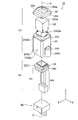
- FIG. 2 is an exploded perspective view of the camera device illustrated in FIG. 1.
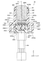
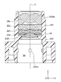
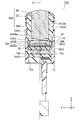
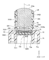
- FIG. 3 is a longitudinal sectional view taken along line III-III in FIG.
- FIG. 4 is a longitudinal sectional view taken along line IV-IV in FIG. 1.
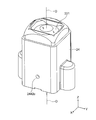
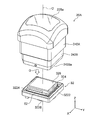
- It is a longitudinal cross-sectional perspective view in the middle of the assembly of the lens unit used for the camera apparatus of FIG.
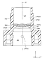
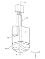
- It is a longitudinal cross-sectional view which shows the state which press-fit the 4th plastic lens (lower lens) in the barrel part from upper direction.
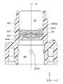
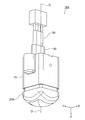
- It is a longitudinal cross-sectional view which shows the state which press-fitted the 3rd plastic lens in the barrel part from upper direction.
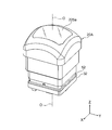
- FIG. 16 is a perspective view illustrating a state in which an adhesive tape is pasted on the upper surface of the image sensor of the sensor substrate assembly illustrated in FIG. 15.
- FIG. 16 is a perspective view illustrating a configuration of the sensor substrate assembly illustrated in FIG. 15 in detail.
- FIG. 17 is a perspective view illustrating a configuration of the sensor substrate assembly illustrated in FIG. 16 in detail. It is the perspective view which looked at the power supply board assembly used for the camera apparatus shown in FIG. 1 from the surface side. It is the perspective view which looked at the power supply board assembly used for the camera apparatus shown in FIG. 1 from the back surface side.
- FIG. 23 is a perspective view illustrating in detail a configuration of a power supply board assembly illustrated in FIG. 22.
- FIG. 24 is a perspective view showing in detail the configuration of the power supply board assembly shown in FIG. 23.
- FIG. 26 is an exploded perspective view showing a state where the first connector of the sensor board unit shown in FIG. 19 and the second connector of the power board unit shown in FIG. 25 are about to be fitted together. It is a perspective view which shows the board
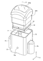
- FIG. 30 is an exploded cross-sectional perspective view illustrating a state where the substrate unit illustrated in FIG. 29 is to be inserted into the holding member of the lens unit illustrated in FIG. 14. It is a disassembled cross-sectional perspective view showing a state in which the focal length and the rotation inclination are adjusted to optimum positions so as to eliminate the deviation of the optical axis between the lens unit and the substrate unit. It is a fragmentary sectional perspective view which expands and shows the adhesion location of the sensor board
- FIG. 32 shows a state where the camera module shown in FIG.
- FIG. 38 is a bottom view showing a state in which a corner portion of the sensor substrate shown in FIG. 37 is abutted against the abutting portion of the holding member of the lens unit shown in FIG.
- FIG. 2 is a diagram illustrating a state in which the camera device illustrated in FIG. 1 is attached to an automobile AM as an in-vehicle camera VC, where (A) is a perspective view of the automobile AM viewed from the rear side, and (B) is a front view of the automobile AM. It is the front view seen from the side. It is an external appearance perspective view of the camera apparatus which concerns on the 2nd Embodiment of this invention.
- FIG. 1 is attached to an automobile AM as an in-vehicle camera VC, where (A) is a perspective view of the automobile AM viewed from the rear side, and (B) is a front view of the automobile AM. It is the front view seen from the side. It is an external appearance perspective view of the camera apparatus which concerns on the 2nd Embodiment of this invention.
- FIG. 42 is a longitudinal sectional view taken along line XLII-XLII in FIG. 41.
- FIG. 42 is a longitudinal sectional view taken along line XLIII-XLIII in FIG. 41.
- FIG. 41 is an exploded perspective view showing a state where the sensor substrate unit is applied to the lower end of the barrel of the lens unit after the adhesive is applied on the surface of the sensor substrate of the sensor substrate unit used in the camera device shown in FIG. It is. It is a perspective view which shows the state which adhere
- FIG. 48 is a perspective view showing a state where the first camera module shown in FIG. 45 is to be inserted into the bracket of FIG. 47 from above.
- FIG. 48 is a longitudinal sectional view showing a state in which the camera module shown in FIG. 45 is inserted up to the first to third substrate receivers of the bracket shown in FIG. 47. It is a perspective view which shows the state which apply
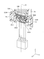
- FIG. 25 It is a disassembled perspective view which shows the state which tries to insert the power supply board unit shown in FIG. 25 toward the board
- FIG. 25 It is a disassembled cross-sectional perspective view which shows the state which tries to insert the power supply board unit shown in FIG. 25 toward the board
- FIG. 6 is a cross-sectional perspective view showing a state in which the second camera module is assembled by fitting the first connector of the sensor board unit and the second connector of the power board unit.
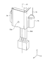
- FIG. 54 is a perspective view showing a state where the second camera module shown in FIG. 53 is turned upside down. It is a perspective view which shows the state which sealed the sealing member in the lower part of the bracket in the 2nd camera module shown in FIG. 56, and assembled the camera apparatus shown in FIG.
- the illustrated camera device 10 includes an in-vehicle camera used as a back monitor camera at the rear of the vehicle body.
- the camera device 10 may be an in-vehicle camera used as a camera such as a front monitor camera at the front of the vehicle body.
- FIG. 1 is an external perspective view of the camera device 10.
- FIG. 2 is an exploded perspective view of the camera apparatus 10.
- 3 is a longitudinal sectional view taken along line III-III in FIG. 4 is a longitudinal sectional view taken along line IV-IV in FIG.
- an orthogonal coordinate system (X, Y, Z) is used.
- the X-axis direction is the front-rear direction (depth direction)
- the Y-axis direction is the left-right direction (width direction)
- Z The axial direction is the vertical direction (height direction).
- the vertical direction Z is the direction of the optical axis O of the lens.
- the upward direction of the vertical direction Z is a direction in which a subject (not shown) exists.
- the Y-axis direction (left-right direction) is also called a first direction
- the X-axis direction (front-back direction) is also called a second direction.
- “sealing” means closing the opening.
- the board constituting the board unit 30 is a printed wiring board (PWB). Therefore, the substrate unit 30 is also called a PWB unit.
- the lens unit 20 includes a lens group 22, a holding member 24 for holding the lens group 22, and a retainer 26 for preventing water from entering the holding member 24.
- the lens group 22 includes a plurality of lenses (described later).
- the lens group 22 includes five lenses.
- Each of the five lenses has an outer shape that does not have an unused area of an imaging element 3224 described later.
- the outer shape of the five lenses is a rectangle corresponding to the outer shape of the image sensor 3224.
- the illustrated holding member 24 includes a barrel portion 242 for shielding the lens group 22 and a bracket portion 244 for attaching the lens device 10 to another device such as a vehicle body.
- the barrel portion 242 and the bracket portion 244 Has an integrated structure.
- the holding member 24 is made of resin.
- the barrel portion 242 of the holding member 24 has a cylindrical portion 2422 having a substantially square cylindrical shape extending in the vertical direction Z.
- the cylindrical portion 2422 has a lens housing inner wall surface 2422 a that matches the outer shape of the lens group 22. Further, the barrel portion 242 protrudes radially inward from the lens housing inner wall surface 242a of the cylindrical portion 2422 in order to lock the lowermost lens (described later) of the lens group 22 to the lower end portion thereof.
- a rectangular ring-shaped locking portion 2424 is provided.
- the locking portion 2424 has a locking surface 2424a on its upper surface.
- “locking” means stopping by engaging with each other.
- a lens housing space LS for housing the lens group 22 is defined by a combination of the lens housing inner wall surface 2422a of the cylindrical portion 2422 and the locking surface 2424a of the locking portion 2424.
- cylindrical portion 2422 of the barrel portion 242 has a retainer receiving surface 2422b formed at the upper end portion thereof so as to be recessed radially inward from the outer wall of the cylindrical portion 2422 of the barrel portion 242 in order to receive the retainer 26. .
- the plurality of lenses constituting the lens group 22 are sequentially inserted into the barrel portion 242 of the holding member 24 from above, and are accommodated and held in the lens accommodation space LS of the barrel portion 242.
- the bracket portion 244 of the holding member 24 includes a rectangular tubular portion 2442 that extends continuously downward from the tubular portion 2422 of the barrel portion 242, and the left and right direction Y from the tubular portion 2442. And a pair of screw holding portions 2444 provided to protrude outward.
- Each screw holding portion 2444 has a semi-cylindrical outer shape and has a screw insertion hole 2444a drilled in the vertical direction Z.
- “drilling” means providing a hole.
- the retainer 26 is attached to the upper end of the cylindrical portion 2422 of the barrel portion 242 of the holding member 24 as will be described later.
- the retainer 26 is provided so as to protrude from the outer cylinder part 262 obliquely upward and inward at the upper end of the outer cylinder part 262 and the substantially cylindrical outer cylinder part 262 extending in the vertical direction Z.
- an upper end portion 264 having a curved ring shape.
- the upper end 264 has a substantially rectangular opening 264 a that matches the outer shape of the lens group 22.
- the outer cylindrical portion 262 of the retainer 26 is received by the retainer receiving surface 2422b of the cylindrical portion 2422 of the barrel portion 242. Further, the upper surface 225a of the uppermost upper lens (described later) of the lens group 22 is exposed from the opening 264a of the upper end 264 of the retainer 26, as will be described later. That is, the retainer 26 is attached to the barrel portion 242 of the holding member 24 so as to surround the outer peripheral edge of the upper lens with the upper surface 225a of the upper lens exposed.
- the inner wall surface of the cylindrical portion 2442 communicates with the lens housing inner wall surface 2422a via the locking portion 2424 to accommodate a substrate module of the substrate unit 30 described later.
- the cylindrical portion 2442 includes a lower cylindrical portion 2442-1 having a large accommodating space width (diameter) and an upper cylindrical portion 2442-2 having a small accommodating space width (diameter) following the lower cylindrical portion 2442-1. It consists of.
- a step between the lower cylindrical portion 2442-1 and the upper cylindrical portion 2442-2 is used as a substrate mounting surface 2442b for mounting a sensor substrate 3222 of the sensor substrate unit 32 of the substrate unit 30 described later.
- a substrate accommodation space SS for accommodating the substrate module of the substrate unit 30 is defined by the combination of the substrate accommodation inner wall surface 2442a and the substrate mounting surface 2442b.
- the cylindrical portion 2442 has an air in the substrate accommodation space SS when the hot melt adhesive is filled in the substrate accommodation space SS of the bracket portion 244.
- the pair of air vent holes 2442 c are formed in the center part of the pair of side surfaces facing the front-rear direction X of the cylindrical part 2442.
- the substrate unit 30 includes a sensor substrate unit 32 and a power supply substrate unit 34.
- the sensor substrate unit 32 is also called a sensor PWB unit
- the power supply substrate unit 34 is also called a power supply PWB unit.
- the sensor board unit 32 includes an image sensor (described later), and the detailed configuration thereof will be described later.
- the power supply board unit 34 includes a power supply board assembly 342 and a harness assembly 344, the detailed configuration of which will be described later.
- the power board assembly 342 is also referred to as a power PWB assembly.
- the sealing member 40 seals the lower part of the holding member 24 as described later.
- FIG. 5 is a vertical cross-sectional perspective view showing the lens unit 20 being assembled.
- the lens group 22 includes a plastic lens group including the first to fourth lenses 221, 222, 223, and 224 illustrated in FIG. 5 and a glass lens including the fifth lens 225 (see FIG. 11). It is configured.
- the first to fourth lenses 221 to 224 are also called first to fourth plastic lenses, respectively.
- the fourth plastic lens 224 is provided at the lowermost part of the lens group 22, it is called a lower lens.
- the fifth lens 225 is provided at the uppermost part of the lens group 22, it is called an upper lens.
- the plastic lens group (221 to 224) of the lens group 22 is lightly press-fitted into the barrel portion 242 of the holding member 24.
- a fourth plastic lens (lower lens) 224 is press-fitted into the barrel portion 242 from above. At this time, the lower surface of the fourth plastic lens 224 is locked by the locking surface 2424a of the locking portion 2424 of the barrel portion 242. Accordingly, the fourth plastic lens 224 is positioned at a normal position in the lens housing space LS of the barrel portion 242.
- the third plastic lens 223 is press-fitted into the barrel portion 242 from above. Thereby, the lower surface of the third plastic lens 223 and the upper surface of the fourth lens plastic 224 come into contact with each other.
- “contact” means contacting with the abutted state.
- the third plastic lens 223 is also positioned at a normal position in the lens housing space LS of the barrel portion 242.
- the second plastic lens 222 is press-fitted into the barrel portion 242 from above. Thereby, the lower surface of the second plastic lens 222 and the upper surface of the third plastic lens 223 come into contact with each other. Accordingly, the second plastic lens 222 is also positioned at a proper position in the lens housing space LS of the barrel portion 242.
- the first plastic lens 221 is press-fitted into the barrel portion 242 from above.
- the lower surface of the first plastic lens 221 and the upper surface of the second plastic lens 222 come into contact with each other. Accordingly, the first plastic lens 221 is also positioned at a proper position in the lens housing space LS of the barrel portion 242.
- FIG. 10 is a perspective view showing a state in which the plastic lens group including the first to fourth plastic lenses 221 to 224 is lightly press-fitted into the barrel portion 242 in this way.
- a glass lens which is a fifth lens (upper lens) 225 is placed on the first plastic lens 221.
- the lower surface of the fifth lens 225 and the upper surface of the first plastic lens 221 come into contact with each other.
- the fifth lens 225 is also positioned at a proper position in the lens housing space LS of the barrel portion 242.
- an adhesive (not shown) is applied to the outer periphery of the fifth lens (upper lens) 225.
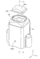
- the retainer 26 is put on the upper end of the holding member 24 as shown by the white arrow A from above and is adhered with an adhesive.
- the retainer 26 is fixed to the holding member 24 by thermosetting in an oven.
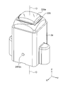
- the upper surface 225 a of the fifth lens (upper lens) 225 is exposed from the opening 264 a of the retainer 26. In this way, the lens unit 20 is assembled.
- the lens unit 20 is assembled by preparing a lens group (22) including a plurality of lenses (221 to 225) each having an outer shape that does not have an unused area of the image pickup element (3224).
- a lens group preparation step and a plurality of lenses (221 to 225) are inserted in order from above into a cylindrical holding member (24) having a lens housing inner wall surface (2422a) that matches the outer shape of the lens group (22).
- a retainer having an opening (264a) surrounding the outer periphery of the upper lens (225) with the upper surface (225a) of the upper lens (225) of the lens group (22) provided in the lens group (22) exposed. Including a retainer mounting step of mounting the upper end of the holding member (24) 6).
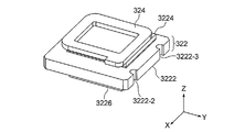
- the sensor substrate unit 32 includes a sensor substrate assembly 322, an adhesive tape 324, and an infrared cut filter (IRCF) 326.
- the sensor substrate assembly 322 is also referred to as a sensor PWB assembly.
- the adhesive tape 324 is made of a double-sided tape (adhesive material).
- FIG. 15 is a perspective view of the sensor substrate assembly 322 as viewed from the front surface side
- FIG. 16 is a perspective view of the sensor substrate assembly 322 as viewed from the back surface side.
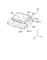
- the sensor board assembly 322 includes a sensor board 3222, an image sensor 3224, and a first connector 3226.
- the sensor substrate 3222 is also called a sensor PWB.
- the first connector 3226 is also called a sensor-side connector. In the illustrated example, the first connector 3226 is formed of a plug connector (male connector).
- an image sensor 3224 is mounted on the surface of the sensor substrate 3222.
- a first connector 3226 is mounted on the back surface of the sensor substrate 3222.
- the image sensor 3224 captures the subject image formed by the lens group 22 and converts it into an electrical signal.
- the imaging element 3224 is configured by, for example, a charge coupled device (CCD) image sensor, a complementary metal oxide semiconductor (CMOS) image sensor, or the like.
- CCD charge coupled device
- CMOS complementary metal oxide semiconductor
- an adhesive tape 324 is pasted on the upper surface of the image sensor 3224 of the sensor substrate assembly 322.
- an infrared cut filter (IRCF) 326 is attached to the adhesive tape 324 and mounted on the image sensor 3224 as indicated by the white arrow B in FIG.
- FIG. 20 and 21 are diagrams showing the configuration of the sensor substrate assembly 322 in more detail.
- FIG. 20 is a perspective view of the sensor substrate assembly 322 as viewed from the front surface side
- FIG. 21 is a perspective view of the sensor substrate assembly 322 as viewed from the back surface side.
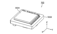
- the sensor board assembly 322 is mounted on the sensor board 3222 as a mounting component in addition to the image sensor 3224 and the sensor side connector (plug connector) 3226, as well as a chip capacitor and a chip resistor. Flash ROM (read only memory), crystal oscillator, etc. are mounted.
- the power supply board unit 34 includes a power supply board assembly 342 and a harness assembly 344.
- the power board assembly 342 is also referred to as a power PWB assembly.
- FIG. 22 is a perspective view of the power supply board assembly 342 as viewed from the front surface side
- FIG. 23 is a perspective view of the power supply board assembly 342 as viewed from the back surface side.
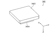
- the power supply board assembly 342 includes a power supply board 3422 and a second connector 3424.
- the power supply board 3422 is also referred to as a power supply PWB.
- the second connector 3424 is also called a power supply side connector.
- the second connector 3424 is formed of a receptacle connector (female connector).
- a second connector 3424 is mounted on the surface of the power supply board 3422.
- the cable (electric wire) 3442 of the harness assembly 344 is soldered to the back surface of the power supply board assembly 342 by hand.
- FIG. 26 and 27 are diagrams showing the configuration of the power supply board assembly 342 in more detail.
- FIG. 26 is a perspective view of the power supply board assembly 342 as viewed from the front surface side
- FIG. 27 is a perspective view of the power supply board assembly 342 as viewed from the back surface side.
- the power supply board assembly 342 is mounted on the power supply board 3422 as not only a power supply side connector (receptacle connector) 3424 but also a chip capacitor, chip resistor, flash ROM ( read only memory) and crystal oscillators are implemented.
- the first connector (plug connector) 3226 of the sensor board unit 32 and the second connector (receptacle connector) 3424 of the power board unit 34 are fitted.
- the combination of the first connector 3226 and the second connector 3424 is called an inter-board connector (3226, 3424). Therefore, the sensor board unit 32 and the power board unit 34 are fitted via the board-to-board connectors (3226, 3424).
- the combination of the sensor board assembly 322 of the sensor board unit 32 and the power board assembly 342 of the power board unit 34 is referred to as the above-described board module (322, 342).
- the substrate modules (322, 342) are accommodated in the substrate accommodating space SS of the holding member 24, as will be described later.
- an adhesive 52 is applied on the sensor substrate 3222 of the substrate unit 30.
- an acrylic-epoxy resin is used as the adhesive 52, but is not limited thereto.
- the substrate unit 30 is inserted into the holding member 24 of the lens unit 20 as indicated by the white arrow C, and the substrate unit 30 is bonded to the lens unit 20 via an adhesive 52. To do.
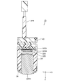
- the focal length and the rotation inclination are adjusted to optimum positions so as to eliminate the deviation of the optical axis O between the lens unit 20 and the substrate unit 30.
- adjustment is performed so that the center of the imaging element 3224 is aligned with the center of the optical axis O and the focus position of the lens group 22.
- FIG. 33 is an enlarged partial cross-sectional perspective view showing an adhesion portion of the sensor substrate 3222 of the substrate unit 30. 33, the sensor substrate 3222 of the substrate unit 30 is bonded to the substrate mounting surface 2442b of the holding member 24 via the adhesive 52.
- UV fixing is applied to the above-mentioned bonding portion and temporarily fixed, it is thermally cured in an oven and fixed.
- the camera module (20, 30) in which the substrate unit 30 is fixed to the lens unit 20 is assembled.
- the camera module (20, 30) is turned upside down and set in a dedicated mold 60. Thereafter, as indicated by an arrow E in FIG. 34, the hot melt adhesive 42 is injected into the mold 60, and the hot melt adhesive 42 is filled into the camera module (20, 30). Thereby, the gap (substrate housing space SS) between the holding member 24 and the substrate unit 30 is sealed with the hot melt adhesive 42. Thereafter, the hot melt adhesive 42 is naturally cured at room temperature.
- thermoplastic plastic such as ethylene vinyl acetate (EVA) can be used, but is not limited thereto.
- EVA ethylene vinyl acetate
- the mold 60 is removed from the camera module (20, 30) filled with the hot melt adhesive 42, and the resin pool 44 is cut. Thereby, the lower part of the holding member 24 is sealed with the sealing member 40.
- the camera device 10 is assembled by a sensor board unit (32) including a sensor board assembly (322) on which an image sensor (3224) is mounted.
- 34) and the sensor board unit (32) are fitted via the inter-board connectors (3226, 3424) to assemble the board unit (30), and the board unit (30) is held by the holding member (24).
- FIG. 36 is a bottom view of the lens unit 20
- FIG. 37 is a bottom view of the sensor substrate unit 32 of the substrate unit 30.
- the bracket portion 244 of the holding member 24 of the lens unit 20 is one corner of the lower cylindrical portion 2442-1 and in the vicinity of the substrate mounting surface 2442b, and the substrate housing inner wall surface 2442a. And an L-shaped butting portion 2446 formed so as to project inward from the inside. Further, the bracket portion 244 has first to third protrusions 2448-1, 2448-2, and 2448-3 projecting inwardly from the substrate housing inner wall surface 2442a of the lower cylindrical portion 2442-1. The first protrusion 2448-1 is formed at the center of the left wall surface in the left-right direction Y of the substrate housing inner wall surface 2442a.
- the second and third protrusions 2448-2 and 2448-3 are formed symmetrically with respect to the straight line in the left-right direction Y passing through the optical axis O on both end sides of the right wall surface in the left-right direction Y of the substrate housing inner wall surface 2442 a. ing.
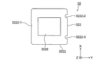
- the sensor substrate 3222 in the sensor substrate assembly 322 of the sensor substrate unit 32 of the substrate unit 30 has first to third slits 3222-1, 3222-2, and 3222 formed on the side surfaces thereof. -3.
- the first slit 3222-1 is formed at the center of the left side surface of the sensor substrate 3222 in the left-right direction Y.
- the second and third slits 3222-2 and 3222-3 are formed symmetrically with respect to a straight line in the left-right direction Y passing through the optical axis O on both end sides of the right side surface in the left-right direction Y of the sensor substrate 3222. . That is, the first to third slits 3222-1 to 3222-3 are provided at positions corresponding to the first to third protrusions 2448-1 to 2448-3, respectively.
- the substrate unit 30 when the substrate unit 30 is inserted into the holding member 24 of the lens unit 20, first, as shown in FIG.
- the first through third slits 3222-1 through 3222-3 of the sensor board unit 32 of the board unit 30 are passed through the first through third 2448-1 through 2448-3, respectively.
- the substrate unit 30 is moved with respect to the lens unit 20, so that the abutting portion 2446 of the holding member 24 of the lens unit 20 is moved to the sensor unit 2446 as shown in FIG.
- the corner of the substrate 3222 is abutted.
- the substrate unit 30 is inserted into the holding member 24 of the lens unit 20.
- the camera apparatus 10 can be easily assembled with a small number of parts.
- FIG. 40 is a diagram illustrating a state in which the camera device 10 is attached to the automobile AM as the in-vehicle camera VC.
- 40A is a perspective view of the automobile AM viewed from the rear side
- FIG. 40B is a front view of the automobile AM viewed from the front side.
- the camera device 10 is attached as a back monitor camera VC to the rear of the vehicle AM.
- the camera device 10 is attached as a front monitor camera VC to the front of the vehicle AM.
- the illustrated camera device 10A also includes an in-vehicle camera used as a back monitor camera VC at the rear of the vehicle body.
- the camera device 10A may also be an in-vehicle camera used as a camera VC such as a front monitor camera at the front of the vehicle body.
- FIG. 41 is an external perspective view of the camera device 10A. 42 is a longitudinal sectional view taken along line XLII-XLII in FIG. 43 is a longitudinal sectional view taken along line XLIII-XLIII in FIG.
- an orthogonal coordinate system (X, Y, Z) is used.
- the X-axis direction is the front-rear direction (depth direction)
- the Y-axis direction is the left-right direction (width direction)
- Z The axial direction is the vertical direction (height direction).
- the vertical direction Z is the direction of the optical axis O of the lens.
- the upward direction of the vertical direction Z is a direction in which a subject (not shown) exists.
- the Y-axis direction (left-right direction) is also called a first direction
- the X-axis direction (front-back direction) is also called a second direction.
- the illustrated camera apparatus 10A has the same configuration as that of the camera apparatus 10 according to the first embodiment except that the configuration of the lens unit is different and the bracket 70 is further provided as a separate body. Accordingly, reference numeral 20A is attached to the lens unit.
- the same components as those of the camera device 10 according to the first embodiment are denoted by the same reference numerals, and the description thereof is omitted for the sake of simplicity. In the following, only differences from the camera device 10 according to the first embodiment will be described in detail.
- the camera device 10A is largely composed of four components. That is, the camera device 10 ⁇ / b> A includes the lens unit 20 ⁇ / b> A, the bracket 70, the substrate unit 30, and the sealing member 40.
- the lens unit 20A has the same configuration as the lens unit 20 of the first embodiment except that the configuration of the holding member is different. Therefore, the reference numeral 24A is attached to the holding member.
- the holding member 24 has a structure in which the barrel portion 242 and the bracket portion 244 are integrated.
- the holding member 24A is composed of only the barrel 242A.
- the barrel part 242 of the holding member 24 according to the first embodiment is composed of only a cylindrical part 2422 and a locking part 2424.
- the barrel 242A of the holding member 24A has a rectangular cylindrical lower portion extending downward from the locking portion 2424 in addition to the cylindrical portion 2422 and the locking portion 2424.
- a portion 2426 is also included.
- the lower surface 2426a of the lower extension portion 2426 serves as a substrate mounting surface for mounting the sensor substrate 3222 of the sensor substrate unit 32 of the substrate unit 30.
- the bracket 70 has substantially the same configuration as the bracket portion 244 of the holding member 24 of the first embodiment, except that the bracket 70 is changed as described later.
- bracket portion 244 of the first embodiment is configured only from the cylindrical portion 2442 and the pair of screw holding portions 2444.
- the bracket 70 of the second embodiment extends not only from the cylindrical portion 72 and the pair of screw holding portions 74 but also from the cylindrical portion 72 to the holding member 24A (barrel 242A). And an upper extending portion 76 that covers the outer wall surface.
- Each screw holding portion 74 has a semi-cylindrical outer shape, and has a screw insertion hole 74a drilled in the vertical direction Z.
- the inner wall surface of the cylindrical portion 72 of the bracket 70 serves as a substrate housing inner wall surface 72 a that houses the substrate unit 30.
- the cylindrical part 72 of the bracket 70 has a pair of air vent holes 72b.
- the assembly method of the lens unit 20A is substantially the same as the assembly method of the lens unit 20 according to the first embodiment described above, except that the holding member 24 is changed to the holding member 24A. Omitted.
- the assembling method of the lens unit 20A is a lens group preparation for preparing a lens group (22) including a plurality of lenses (221 to 225) each having an outer shape that does not have an unused area of the image sensor (3224). Inserting the plurality of lenses (221 to 225) in sequence from above into a cylindrical holding member (24A) having a lens housing inner wall surface (2422a) that matches the outer shape of the lens group (22), A lens group holding step for holding the lens group (22) in the holding member (24A), and an upper end of the holding member (24A) for preventing water from entering the holding member (24A).
- a retainer having an opening (264a) surrounding the outer peripheral edge of the upper lens (225).
- a retainer mounting step of mounting the upper end of the holding member (24A) to (26).
- the method for assembling the sensor substrate unit 32 and the power supply substrate unit 34 is also the same as the method for assembling the sensor substrate unit 32 and the power supply substrate unit 34 of the first embodiment described above.
- an adhesive 52 made of acrylic-epoxy resin is applied on the surface of the sensor substrate 3222 of the sensor substrate unit 32. Subsequently, as indicated by the white arrow G in FIG. 44, the sensor substrate unit 32 is abutted against the lower end (substrate mounting surface) 2426a of the barrel 242A of the lens unit 20A.
- the sensor substrate unit 32 is bonded to the lens unit 20A via the adhesive 52.
- the focal length and the rotation inclination are adjusted to the optimum positions so as to eliminate the deviation of the optical axis O between the lens unit 20A and the sensor substrate unit 32.
- adjustment is performed so that the center of the imaging element 3224 is aligned with the center of the optical axis O and the focus position of the lens group 22.
- the sensor substrate 3222 of the sensor substrate unit 32 is bonded to the substrate mounting surface 2426a of the holding member 24A.
- UV fixing is applied to the above-mentioned bonding portion and temporarily fixed, it is thermally cured in an oven and fixed.
- the first camera module (20A, 32) in which the sensor substrate unit 32 is fixed to the lens unit 20A is assembled.
- FIG. 47 is a plan view of the bracket 70.
- the bracket 70 has first to third substrate receivers 78-1, 78-2, and 78-3 projecting inwardly from the substrate accommodating inner wall surface 72a of the cylindrical portion 72.
- the first substrate receiver 78-1 is formed at the center of the left wall surface in the left-right direction Y of the substrate housing inner wall surface 72a.
- the second and third substrate receivers 78-2 and 78-3 are formed symmetrically with respect to the straight line in the left-right direction Y passing through the optical axis O on both end sides of the right wall surface in the left-right direction Y of the substrate housing inner wall surface 72a. Has been.
- the first camera module (20A, 32) is inserted into the bracket 70 from above the bracket 70, as indicated by the white arrow H in FIG.
- the first camera module (20A, 32) is inserted into the first to third substrate receivers 78-1 to 78-3 of the bracket 70.
- an adhesive 54 made of, for example, an epoxy resin is applied around the upper opening of the bracket 70. Thereafter, the adhesive 54 is cured in an oven.
- bracket 70 is attached to the first camera module (20A, 32).
- the power supply board unit 34 is inserted from below toward the board housing space SS of the first camera module (20A, 32).
- the first connector (plug connector) 3226 of the sensor board unit 32 and the second connector (receptacle connector) 3424 of the power board unit 34 are fitted.
- the board unit 30 in which the board unit 32 and the power board unit 34 are fitted via the board-to-board connectors (3226, 3424) is assembled.
- the combination of the lens unit 20A, the bracket 70, and the substrate unit 30 is called a second camera module (20A, 70, 30).
- FIGS. 34 and 35 in addition to FIGS. 55 and 56, a method of sealing the lower part of the bracket 70 of the second camera module (20A, 70, 30) with the sealing member 40 will be described. explain.
- the second camera module (20A, 70, 30) is turned upside down.
- the second camera module (20A, 70, 30) turned upside down is set in a dedicated mold 60.
- the hot melt adhesive 42 is injected into the mold 60, and the hot melt adhesive 42 is filled into the second camera module (20A, 70, 30). .
- the gap (substrate housing space SS) between the bracket 70 and the substrate unit 30 is sealed by the hot melt adhesive 42.
- the hot melt adhesive 42 is naturally cured at room temperature.
- a resin pool 44 is formed in the mold 60.
- the mold 60 is removed from the second camera module (20A, 70, 30) filled with the hot melt adhesive 42, and the resin pool 44 is cut.
- the camera device 10A can be assembled by barreling the sensor substrate unit (32) including the sensor substrate assembly (322) on which the image sensor (3224) is mounted in addition to the above-described assembly method of the lens unit 20A.
- the sensor substrate is aligned with the lower end of the barrel (242A) while adjusting so that the center of the imaging element (3224) is aligned with the center of the optical axis (O) and the focal point of the lens group (22).
- the camera module (20A, 32) is inserted into a module assembling step for fixing the unit (32) and assembling the camera module (20A, 32) and a bracket (70) for attaching the camera device to another device.
- the module mounting process for mounting and the harness assembly (on the power board assembly (342)) 44) and soldering the cable (3442) to assemble the power supply board unit (34), and the power supply board unit (34) and the sensor board unit (32) are connected to each other (3226, 3424).
- the camera device 10A can be assembled more easily than the camera device 10 according to the first embodiment described above. Become.
- the holding member 24 is configured by integrating the barrel portion 242 and the bracket portion 244, so that the holding member 24 has too many functions.
- the function of the holding member 24 in the first embodiment can also be separated, which makes it easier to assemble. It is.
- the outer shape of the lens group (22) is preferably rectangular.
- the retainer attaching step may be a step of attaching the retainer (26) by fixing the retainer (26) to the upper end of the holding member (24; 24A) with an adhesive (52).
- the holding member (24) includes a barrel portion (242) for shielding the lens group (22) and a bracket portion (for attaching the camera device (10) to another device ( 244), and the barrel portion (242) and the bracket portion (244) may be integrated.
- the assembling method of the camera device (10) includes a sensor substrate unit preparation step of preparing a sensor substrate unit (32) including a sensor substrate assembly (322) on which an image pickup device (3224) is mounted, and a power supply substrate assembly ( 342) is attached to the harness assembly (344) to assemble the power supply board unit (34), the power supply board unit (34) and the sensor board unit (32) are joined, and the board unit (30) Board unit assembly step, the board unit (30) is inserted into the holding member (24) from below, and the image sensor (3224) is placed at the center of the optical axis (O) and the focal point of the lens group (22). Adjusting to align the center, communicate with the lens housing inner wall surface (2422a) and under the holding member (24).
- the substrate unit fixing step may be a step of fixing the sensor substrate unit (32) to the substrate housing inner wall surface (2442a) of the holding member (24) with an adhesive (52).
- the sealing step the lower portion of the holding member (24) is filled with the adhesive (42), and the gap (SS) between the holding member (24) and the substrate unit (30) is sealed in the sealing member (40). It may be a step of sealing with.
- the holding member (24A) may be constituted by a barrel (242A) that shields the lens group (22).
- the assembly method of the camera device (10A) is as follows.
- the sensor substrate unit (32) including the sensor substrate assembly (322) on which the image sensor (3224) is mounted is abutted against the lower end of the barrel (242A), and the lens group ( 22), the sensor substrate unit (32) is fixed to the lower end of the barrel (242A) while adjusting so that the center of the image pickup device (3224) is aligned with the center of the optical axis (O) and the focal point of 22).
- the module assembly step may be a step of fixing the sensor substrate unit (32) to the lower end of the barrel (242A) with an adhesive (52).
- the adhesive (42) is filled in the lower part of the bracket (242A), and the gap (SS) between the bracket (242A) and the substrate unit (30) is sealed with the sealing member (40). It may be a step of stopping.
- the camera device (10; 10A) may be composed of an in-vehicle camera mounted on the vehicle body.
- a lens group preparation step of preparing a lens group (22) composed of a plurality of lenses (221 to 225) each having an outer shape without a lens, and a plurality of lenses (221 to 225) in order of the lens group (22) A lens group that is inserted from above into a cylindrical holding member (24; 24A) having a lens housing inner wall surface (2422a) that matches the outer shape and holds the lens group (22) in the holding member (24; 24A).
- the outer shape of the lens group (22) is preferably rectangular.
- the retainer attaching step may be a step of attaching the retainer (26) by fixing it to the upper end of the holding member (24; 24A) with an adhesive.
- the holding member (24) includes a barrel portion (242) that shields the lens group (22) and a bracket portion (244) that attaches the camera device (10) to another device. ) And the bracket portion (244) may be integrated.
- the holding member (24A) may be constituted by a barrel (242A) that shields the lens group (22).
- the sealing member is sealed against the lower part of the holding member (bracket) by filling with a hot melt adhesive, but the present invention is not limited to this, and other sealing methods are used. It may be adopted.
- the camera device according to the present invention is not limited to a vehicle-mounted camera, and can be used as a camera used in other fields (for example, the medical field).
Landscapes
- Physics & Mathematics (AREA)
- General Physics & Mathematics (AREA)
- Optics & Photonics (AREA)
- Engineering & Computer Science (AREA)
- Multimedia (AREA)
- Signal Processing (AREA)
- Studio Devices (AREA)
- Lens Barrels (AREA)
Abstract
カメラ装置を少ない部品点数で容易に組み立てるために、カメラ装置(10;10A)の組立て方法は、撮像素子(3224)の使用していない領域を持たない外形形状を各々持つ複数のレンズ(221~225)から成るレンズ群(22)を準備するレンズ群準備工程と、複数のレンズ(221~225)を順番に、レンズ群(22)の外形形状に合致したレンズ収容内壁面(2422a)を持つ筒状の保持部材(24;24A)に上方から挿入して、レンズ群(22)を保持部材(24;24A)内に保持するレンズ群保持工程と、この保持部材(24;24A)の上端に設けられたレンズ群(22)の上部レンズ(225)の上面を露出させた状態で、上部レンズ(225)の外周縁を囲むように、開口(264a)を持つリテーナ(26)を保持部材(24;24A)の上端に取り付けるリテーナ取付け工程と、を含む。
Description
本発明はカメラ装置の組立て方法に関し、特に、車体後部にバックモニタ用カメラとして使用される車載カメラの組立て方法およびその車載カメラに使用されえるレンズユニットの組立て方法に関する。
この種のバックモニタ用カメラ等の車載カメラは、例えば、車体のスポイラーの下部や、ナンバープレート周囲の凹部、バックドアの上部や平坦なバックドア表面等に設置される。このような車載カメラは、車体の外部に設置されるので、防塵・防水性を保つことが必要となる。この種の車載カメラは、従来から種々提案されている。
例えば、特許文献1は、カメラモジュールを内包するフロントカバーと、リアカバーとをネジによって螺合した、車載カメラを開示している。この特許文献1に開示された車載カメラでは、パッキンがフロントカバーとリアカバーの接合部分を覆うことで、接合部分が密閉されている。また、特許文献1の車載カメラにおいて、カメラモジュールの前端にカメラ部が設けられている。
また、特許文献2は、対向するリアケースとフロントケースとをネジ止めなどでしっかりと締め付けて防水性を保つようにした、車載カメラを開示している。特許文献2に開示された車載カメラにおいて、撮像素子を搭載した1枚目の基板は、レンズの光軸中心および合焦点位置に撮像素子の中心を合わせるように、フロントケースに固定されている。換言すれば、NTSC(National Television System Committee)信号から得た画像を解析して、最適な位置に撮像素子を動かし1枚目の基板を接着剤やネジでフロントケースに固定している。1枚目の基板と2枚目の基板は、基板間コネクタで接続されている。2枚目の基板は、映像信号や外部からの電力の供給を受けるハーネスに接続するためのハーネスコネクタを搭載している。
さらに、特許文献3は、車載用モニターカメラ機器等のモジュール機器を外部機器に接続するためのモジュール機器用電気機器を開示している。特許文献3において、モジュール機器は電気機器に装着される。モジュール機器は、撮像素子とカメラレンズを基板上に実装したものである。モジュール機器のコネクタと、ケース本体に設けてある内部接続ワイヤのコネクタとが接続される。モジュール機器は、ケース本体に設けてあるモジュール機器収容部内に、位置合わせして装着される。ケースカバーをケース本体に超音波溶着等で固定して、モジュール機器を電気機器に収納している。モジュール機器を収納したモジュール機器収納部をケースカバーで覆うことで、ケース本体とケースカバーとの間に形成した内部を密閉している。ケース本体は、モジュール機器収納部と、外部接続のための接続開口部とを仕切る収納部隔壁を有する。収納部隔壁は貫通孔を有する。内部接続ワイヤは、貫通孔を経由して、略直角方向に曲げて接続開口部で中継ケーブルと接続してある。貫通孔は接着性樹脂で封止してある。接続開口部は二次成形により形成した二次形成樹脂部で封止してある。
さらにまた、特許文献4は、車載カメラではないが、低コストで簡単な構成でありながら、コンパクトなズームレンズ装置を開示している。ズームレンズ装置は、物体側から順に、正のパワーを有する第1レンズ群、負のパワーを有する第2レンズ群、更にそれに続く後続群と、から成るズームレンズ系を備える。レンズ素子はその外周部が保持筒内に嵌合固定されることにより保持される。CCD(Charge Coupled Device)等の個体撮像素子の受光面は一般に長方形状をしている。そこで、特許文献4は、第1レンズ群のY方向(CCDの短辺方向)の長さが短くなるように、長辺の上下部分に相当するレンズ外周部分を切断しても問題はない、と記載している。第1レンズ群を構成している各レンズ素子は、光軸に対して平行な母線を有する円柱面の一部を光軸に対して平行な平面で切断した形状の外周面を有している。第1レンズ群を構成している各レンズ素子は、前記円柱面の切断された部分を除く外周面で保持される。
さらに、特許文献4は、第1レンズ群のX方向(CCDの長辺方向)の長さが短くなるように、CCDの短辺の左右部分に相当するレンズ外周部分を切断してもよい、と記載している。これにより、CCDの画面フォーマットに合うように外周部分が4平面で切断された矩形レンズが得られる。
上述した特許文献1~4には、それぞれ、次に述べるような問題がある。
特許文献1に開示された車載カメラでは、カメラモジュールを、ネジによって螺合されたフロントカバーとリアカバーとで覆っている。また、フロントカバーとリアカバーの接合部分がパッキンで覆われている。そのため、特許文献1の車載カメラは、部品点数が多くなるという問題がある。また、特許文献1では、カメラモジュールの前端にレンズ部が取付けられている。特許文献1では、レンズ部およびカメラモジュールの構成については詳細に説明していない。一般に、レンズ部は、レンズ(レンズ群)と、そのレンズ(レンズ群)を遮光する部品であるバレルとから成る。したがって、カメラモジュールは、バレルを保持することになる。そのため、特許文献1の車載カメラでは、レンズ(レンズ群)は、バレル、カメラモジュール、およびフロントカバーによって三重に覆われることになる。その結果、特許文献1の車載カメラは、部品点数が多くなり、且つ、その外形寸法も大きくなるという問題がある。
このように、特許文献1に開示された車載カメラは、部品点数が多いので、それを組み立てるのに手間がかかる。
特許文献2に開示された車載カメラでも、対向するリアケースとフロントケースとはネジ止めなどでしっかりと締め付けられている。また、特許文献2の車載カメラでは、2枚目の基板にハーネスコネクタが搭載されている。そのため、特許文献2の車載カメラも、部品点数が多くなるという問題がある。
したがって、特許文献2に開示された車載カメラも、部品点数が多いので、それを組み立てるのに手間がかかる。
特許文献3に開示されたモジュール機器において、カメラレンズは基板上に実装されている。特許文献3では、カメラレンズの詳細な構成について何ら説明していない。しかしながら、カメラレンズを基板上に実装するために、カメラレンズは、レンズ(レンズ群)と、そのレンズ(レンズ群)を遮光する部品(バレル)と、そのバレルを保持する部品(保持部品)とから成ると考えられる。換言すれば、特許文献3のモジュール機器は、上記特許文献1のカメラモジュールに相当(対応)するものと考えられる。したがって、特許文献1と同様に、特許文献3のモジュール機器用電気機器では、レンズ(レンズ群)は、バレル、保持部品、およびケース本体によって三重に覆われることになる。その結果、特許文献3のモジュール機器用電気機器は、部品点数が多くなり、且つ、その外形寸法も大きくなるという問題がある。
したがって、特許文献3に開示されたモジュール機器用電気機器でも、部品点数が多いので、それを組み立てるのに手間がかかる。
一方、特許文献4は、CCDの画面フォーマットに合うように外周部分が4平面で切断された矩形レンズを記載している。しかしながら、特許文献4では、単に、「レンズ素子はその外周部が保持筒内に嵌合固定されることにより保持される」と記載しているだけである。したがって、特許文献4は、どのようにしてレンズ素子を保持筒内に保持するのかについて、具体的に記載していない。換言すれば、特許文献4は、ズームレンズ装置を具体的にどのように組み立てるのかについて何ら開示していない。
したがって、本発明の目的は、カメラ装置を少ない部品点数で容易に組み立てることが可能な、カメラ装置の組立て方法およびカメラ装置に使用されるレンズユニットの組立て方法を提供することにある。
本発明の他の目的は、説明が進むにつれて明らかになるだろう。
尚、本発明の説明で示される上方、上端、上部、上面の文言は、本発明のカメラ装置における光軸O方向の被写体側を示し、下方、下端、下部、下面の文言は、本発明のカメラ装置における光軸O方向の撮像素子側を示すものである。
本発明の第1の例示的な態様によれば、カメラ装置の組立て方法であって、撮像素子の使用していない領域を持たない外形形状を各々持つ複数のレンズから成るレンズ群を準備するレンズ群準備工程と、複数のレンズを順番に、レンズ群の外形形状に合致したレンズ収容内壁面を持つ筒状の保持部材に上方から挿入して、レンズ群を保持部材内に保持するレンズ群保持工程と、保持部材の上端に設けられたレンズ群の上部レンズの上面を露出させた状態で、上部レンズの外周縁を囲むように、開口を持つリテーナを保持部材の上端に取り付けるリテーナ取付け工程と、を含むカメラ装置の組立て方法が得られる。
本発明の第2の例示的な態様によれば、カメラ装置に使用されるレンズユニットの組立て方法であって、撮像素子の使用していない領域を持たない外形形状を各々持つ複数のレンズから成るレンズ群を準備するレンズ群準備工程と、複数のレンズを順番に、レンズ群の外形形状に合致したレンズ収容内壁面を持つ筒状の保持部材に上方から挿入して、レンズ群を保持部材内に保持するレンズ群保持工程と、保持部材の上端に設けられたレンズ群の上部レンズの上面を露出させた状態で、上部レンズの外周縁を囲むように、開口を持つリテーナを保持部材の上端に取り付けるリテーナ取付け工程と、を含むレンズユニットの組立て方法が得られる。
本発明では、カメラ装置を少ない部品点数で容易に組み立てることができる。
[第1の実施形態]
図1乃至図4を参照して、本発明の第1の実施形態に係るカメラ装置10の構造について説明する。図示のカメラ装置10は、後述するように、車体後部にバックモニタ用カメラとして使用される車載カメラから成る。なお、カメラ装置10は、車体前部にフロントモニタ用カメラ等のカメラとして使用される車載カメラであってもよい。
図1乃至図4を参照して、本発明の第1の実施形態に係るカメラ装置10の構造について説明する。図示のカメラ装置10は、後述するように、車体後部にバックモニタ用カメラとして使用される車載カメラから成る。なお、カメラ装置10は、車体前部にフロントモニタ用カメラ等のカメラとして使用される車載カメラであってもよい。
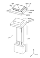
図1はカメラ装置10の外観斜視図である。図2はカメラ装置10の分解斜視図である。図3は図1の線III-IIIについての縦断面図である。図4は図1の線IV-IVについての縦断面図である。
ここでは、図1乃至図4に示されるように、直交座標系(X,Y,Z)を使用している。図1乃至図4に図示した状態では、直交座標系(X,Y,Z)において、X軸方向は前後方向(奥行方向)であり、Y軸方向は左右方向(幅方向)であり、Z軸方向は上下方向(高さ方向)である。そして、図1乃至図4に示す例においては、上下方向Zがレンズの光軸O方向である。図示の例では、上下方向Zの上方向は被写体(図示せず)が存在する方向である。尚、本第1の実施形態において、Y軸方向(左右方向)は第1の方向とも呼ばれ、X軸方向(前後方向)は第2の方向とも呼ばれる。
図示のカメラ装置10は、図2に示されるように、おおきく3つの構成要素から成る。すなわち、カメラ装置10は、レンズユニット20と、基板ユニット30と、封止部材40とから成る。ここで、「封止」とは、開口を閉鎖することをいう。また、図示の例では、基板ユニット30を構成する基板は、プリント配線基板(PWB:printed wiring board)から成る。したがって、基板ユニット30は、PWBユニットとも呼ばれる。
レンズユニット20は、レンズ群22と、このレンズ群22を保持するための保持部材24と、この保持部材24の内部に水が浸入するのを防止するためのリテーナ26とから成る。
レンズ群22は、複数個のレンズ(後述する)から成る。図示の例では、レンズ群22は、5個のレンズから成る。5個のレンズの各々は、後述する撮像素子3224の使用していない領域を持たない外形形状を持つ。図示の例では、5個のレンズの外形形状は、撮像素子3224の外形に対応した矩形から成る。
図示の保持部材24は、レンズ群22を遮光するためのバレル部242と、当該レンズ装置10を車体等の他の装置へ取り付けるためのブラケット部244とを含み、バレル部242とブラケット部244とが一体となった構造をしている。保持部材24は樹脂製である。
保持部材24のバレル部242は、上下方向Zに延在する実質的に四角筒形状をした筒状部2422を有する。筒状部2422は、レンズ群22の外形形状に合致したレンズ収容内壁面2422aを持つ。また、バレル部242は、その下端部に、レンズ群22の一番下側の下部レンズ(後述する)を係止するために、筒状部2422のレンズ収容内壁面242aから半径方向内側へ突出した矩形リング状の係止部2424を有する。係止部2424は、その上面に係止面2424aを持つ。ここで、「係止」とは、係わり合って止まることを意味する。筒状部2422のレンズ収容内壁面2422aと係止部2424の係止面2424aとの組み合わせによって、レンズ群22を収容するレンズ収容空間LSが規定される。
さらに、バレル部242の筒状部2422は、その上端部に、リテーナ26を受けるために、バレル部242の筒状部2422の外壁から半径方向内側へ凹んで形成されたリテーナ受け面2422bを持つ。
後述するように、レンズ群22を構成する複数のレンズは、順番に、保持部材24のバレル部242に上方から挿入され、バレル部242のレンズ収容空間LSに収容されて保持される。
保持部材24のブラケット部244は、バレル部242の筒状部2422から連続して下方に延在して設けられた四角筒形状の筒状部2442と、この筒状部2442から左右方向Yの外側へ突出して設けられた一対のネジ保持部2444とを有する。各ネジ保持部2444は、半円柱の外形をしており、上下方向Zに穿設されたネジ挿入穴2444aを持つ。ここで、「穿設」とは、穴を設けることを意味する。
リテーナ26は、後述のように、保持部材24のバレル部242の筒状部2422の上端に取り付けられる。リテーナ26は、上下方向Zに延在する実質的に四角筒状の外筒部262と、この外筒部262の上端で外筒部262から斜め上方にかつ内側へ突出するように設けられた、曲面リング形状の上端部264と、から成る。上端部264は、上記レンズ群22の外形形状に合致した、実質的に矩形の開口264aを持つ。
リテーナ26の外筒部262は、バレル部242の筒状部2422のリテーナ受け面2422bで受け止められる。また、レンズ群22の一番上側の上部レンズ(後述する)の上面225aは、後述するように、リテーナ26の上端部264の開口264aから露出する。すなわち、リテーナ26は、上部レンズの上面225aを露出させた状態で、上部レンズの外周縁を囲むように、保持部材24のバレル部242に取り付けられる。
保持部材24のブラケット部244において、筒状部2442の内壁面は、 上記レンズ収容内壁面2422aに係止部2424を介して連通して、後述する基板ユニット30の基板モジュールを収容する基板収容内壁面2442aとして働く。筒状部2442は、収容空間の幅(径)が大きい下部筒状部2442-1と、その下部筒状部2442-1に続く収容空間の幅(径)が小さい上部筒状部2442-2とから成る。下部筒状部2442-1と上部筒状部2442-2との間の段差は、後述する基板ユニット30のセンサ基板ユニット32のセンサ基板3222を取り付けるための基板取付け面2442bとして使用される。基板収容内壁面2442aと基板取付け面2442bとの組み合わせによって、基板ユニット30の基板モジュールを収容する基板収容空間SSが規定される。
また、保持部材24のブラケット部244において、筒状部2442は、後述するように、ブラケット部244の基板収容空間SS内にホットメルト接着剤を充填する際に、その基板収容空間SS内の空気を外部へ抜くための一対の空気抜き孔2442cを持つ。図示の例では、一対の空気抜き孔2442cは、筒状部2442の前後方向Xに対向する一対の側面の中央部に穿設されている。
基板ユニット30は、センサ基板ユニット32と、電源基板ユニット34とから成る。センサ基板ユニット32はセンサPWBユニットとも呼ばれ、電源基板ユニット34は電源PWBユニットとも呼ばれる。
センサ基板ユニット32は、撮像素子(後述する)を含むが、その詳細な構成については後で説明する。
電源基板ユニット34は、電源基板アセンブリ342と、ハーネスアセンブリ344とを含むが、その詳細な構成については後で説明する。電源基板アセンブリ342は、電源PWBアセンブリとも呼ばれる。
封止部材40は、後述するように、保持部材24の下部を封止する。
次に、図5乃至図14を参照して、レンズユニット20を組み立てる方法について説明する。
図5は、レンズユニット20の組立て途中を示す縦断面斜視図である。レンズ群22は、図5に示された第1乃至第4のレンズ221、222、223、および224から成るプラスチックレンズ群と、第5のレンズ225(図11参照)から成るガラスレンズと、から構成されている。第1乃至第4のレンズ221~224は、それぞれ、第1乃至第4のプラスチックレンズとも呼ばれる。
第4のプラスチックレンズ224は、レンズ群22の最下部に設けられるので、下部レンズと呼ばれる。一方、第5のレンズ225は、レンズ群22の最上部に設けられるので、上部レンズと呼ばれる。
先ず、図5に示されるように、保持部材24のバレル部242の内部にレンズ群22のプラスチックレンズ群(221~224)を軽圧入する。
詳述すると、図6に示されるように、第4のプラスチックレンズ(下部レンズ)224を上方からバレル部242内に圧入する。このとき、第4のプラスチックレンズ224の下面は、バレル部242の係止部2424の係止面2424aで係止される。これにより、第4のプラスチックレンズ224は、バレル部242のレンズ収容空間LS内の正規な位置に位置決めされる。
次に、図7に示されるように、第3のプラスチックレンズ223を上方からバレル部242内に圧入する。これにより、第3のプラスチックレンズ223の下面と第4のレンズプラスチック224の上面とが互いに当接する。ここで、「当接」とは、突き当てた状態に接することを意味する。これにより、第3のプラスチックレンズ223も、バレル部242のレンズ収容空間LS内の正規な位置に位置決めされる。
引き続いて、図8に示されるように、第2のプラスチックレンズ222を上方からバレル部242内に圧入する。これにより、第2のプラスチックレンズ222の下面と第3のプラスチックレンズ223の上面とが互いに当接する。これにより、第2のプラスチックレンズ222も、バレル部242のレンズ収容空間LS内の正規な位置に位置決めされる。
そして、図9に示されるように、第1のプラスチックレンズ221を上方からバレル部242内に圧入する。これにより、第1のプラスチックレンズ221の下面と第2のプラスチックレンズ222の上面とが互いに当接する。これにより、第1のプラスチックレンズ221も、バレル部242のレンズ収容空間LS内の正規な位置に位置決めされる。
図10は、このようにして第1乃至第4のプラスチックレンズ221~224から成るプラスチックレンズ群をバレル部242に軽圧入した状態を示す斜視図である。
引き続いて、図11に示すように、第5のレンズ(上部レンズ)225であるガラスレンズを第1のプラスチックレンズ221の上に載せる。
これにより、図12に示されるように、第5のレンズ225の下面と第1のプラスチックレンズ221の上面とが互いに当接する。これにより、第5のレンズ225も、バレル部242のレンズ収容空間LS内の正規な位置に位置決めされる。
引き続いて、図12において、第5のレンズ(上部レンズ)225の外周に接着剤(図示せず)を塗布する。
その後、図13に示すように、リテーナ26を上方から白抜き矢印Aで示すように保持部材24の上端に被せて、接着剤で接着する。
最後に、図14に示すように、オーブンにて熱硬化することにより、保持部材24にリテーナ26を固定する。このとき、第5のレンズ(上部レンズ)225の上面225aは、リテーナ26の開口264aから露出する。このようにして、レンズユニット20が組み立てられる。
以上をまとめると、レンズユニット20の組立て方法は、撮像素子(3224)の使用していない領域を持たない外形形状を各々持つ複数のレンズ(221~225)から成るレンズ群(22)を準備するレンズ群準備工程と、複数のレンズ(221~225)を順番に、レンズ群(22)の外形形状に合致したレンズ収容内壁面(2422a)を持つ筒状の保持部材(24)に上方から挿入して、レンズ群(22)を保持部材(24)内に保持するレンズ群保持工程と、保持部材(24)の内部に水が浸入するのを防止するために、保持部材(24)の上端に設けられたレンズ群(22)の上部レンズ(225)の上面(225a)を露出させた状態で、上部レンズ(225)の外周縁を囲むように、開口(264a)を持つリテーナ(26)を保持部材(24)の上端に取り付けるリテーナ取付け工程と、を含む。
次に、図15乃至図19を参照して、センサ基板ユニット32の構成およびその組立て方法について説明する。
図19に示されるように、センサ基板ユニット32は、センサ基板アセンブリ322と、粘着テープ324と、赤外線カットフィルタ(IRCF)326とから成る。センサ基板アセンブリ322は、センサPWBアセンブリとも呼ばれる。粘着テープ324は、両面テープ(粘着材)から成る。
図15は、センサ基板アセンブリ322を表面側からみた斜視図であり、図16は、センサ基板アセンブリ322を裏面側からみた斜視図である。
センサ基板アセンブリ322は、センサ基板3222と、撮像素子3224と、第1のコネクタ3226とを有する。センサ基板3222は、センサPWBとも呼ばれる。また、第1のコネクタ3226は、センサ側コネクタとも呼ばれる。図示の例では、第1のコネクタ3226は、プラグコネクタ(雄型コネクタ)から成る。
図15に示されるように、センサ基板3222の表面上に撮像素子3224が搭載されている。
図16に示されるように、センサ基板3222の裏面上に第1のコネクタ3226が搭載されている。
撮像素子3224は、上記レンズ群22により結像された被写体像を撮像して電気信号に変換する。撮像素子3224は、例えば、CCD(charge coupled device)型イメージセンサ、CMOS(complementary metal oxide semiconductor)型イメージセンサ等により構成される。
次に、図17乃至図19を参照して、センサ基板ユニット32の組立て方法について説明する。
まず、図17に示されるように、センサ基板アセンブリ322の撮像素子3224の上面に、粘着テープ324を貼る。
次に、図18の白抜き矢印Bで示すように、赤外線カットフィルタ(IRCF)326を粘着テープ324に貼って、撮像素子3224上に実装する。
これにより、図19に示されるような、センサ基板ユニット32が組み立てられる。
図20および図21は、センサ基板アセンブリ322の構成をより詳細に示す図である。図20は、センサ基板アセンブリ322を表面側からみた斜視図であり、図21は、センサ基板アセンブリ322を裏面側からみた斜視図である。
図20および図21から明らかなように、センサ基板アセンブリ322は、センサ基板3222上に、その実装部品として、撮像素子3224およびセンサ側コネクタ(プラグコネクタ)3226ばかりでなく、チップコンデンサ、チップ抵抗器、フラッシュROM(read only memory)、水晶発振子などを実装している。
次に、図22乃至図25を参照して、電源基板ユニット34の構成およびその組立て方法について説明する。
図25に示されるように、電源基板ユニット34は、電源基板アセンブリ342と、ハーネスアセンブリ344とから成る。電源基板アセンブリ342は、電源PWBアセンブリとも呼ばれる。
図22は、電源基板アセンブリ342を表面側からみた斜視図であり、図23は、電源基板アセンブリ342を裏面側からみた斜視図である。
電源基板アセンブリ342は、電源基板3422と、第2のコネクタ3424とを有する。電源基板3422は、電源PWBとも呼ばれる。また、第2のコネクタ3424は、電源側コネクタとも呼ばれる。図示の例では、第2のコネクタ3424は、レセプタクルコネクタ(雌型コネクタ)から成る。
図22に示されるように、電源基板3422の表面上に第2のコネクタ3424が搭載されている。
次に、図24及び図25を参照して、電源基板ユニット34の組立て方法について説明する。
図24に示すように、電源基板アセンブリ342の裏面にハーネスアセンブリ344のケーブル(電線)3442を手ではんだ付けする。
これにより、図25に示されるような、電源基板ユニット34が組み立てられる。
図26および図27は、電源基板アセンブリ342の構成をより詳細に示す図である。図26は、電源基板アセンブリ342を表面側からみた斜視図であり、図27は、電源基板アセンブリ342を裏面側からみた斜視図である。
図26および図27から明らかなように、電源基板アセンブリ342は、電源基板3422上に、その実装部品として、電源側コネクタ(レセプタクルコネクタ)3424ばかりでなく、チップコンデンサ、チップ抵抗器、フラッシュROM(read only memory)、水晶発振子などを実装している。
次に、図28および図29を参照して、基板ユニット30の組立て方法について説明する。
図28に示されるように、センサ基板ユニット32の第1のコネクタ(プラグコネクタ)3226と、電源基板ユニット34の第2のコネクタ(レセプタクルコネクタ)3424とを嵌合する。第1のコネクタ3226と第2のコネクタ3424との組み合わせは、基板間コネクタ(3226,3424)と呼ばれる。したがって、センサ基板ユニット32と電源基板ユニット34とは、基板間コネクタ(3226,3424)を介して嵌合される。
これにより、図29に示されるような、基板ユニット30が組み立てられる。
尚、センサ基板ユニット32のセンサ基板アセンブリ322と、電源基板ユニット34の電源基板アセンブリ342との組み合わせは、上述した基板モジュール(322,342)と呼ばれる。基板モジュール(322,342)は、後述するように、保持部材24の上記基板収容空間SS内に収容される。
次に、図30乃至図35を参照して、カメラ装置10の組立て方法について説明する。
先ず、図30に示されるように、基板ユニット30のセンサ基板3222上に、接着剤52を塗布する。図示の例では、接着剤52として、アクリル-エポキシ樹脂を使用しているが、それに限定されない。
次に、図31に示されるように、基板ユニット30をレンズユニット20の保持部材24に白抜き矢印Cで示すように挿入して、基板ユニット30をレンズユニット20に接着剤52を介して接着する。
この接着の際、図32に示されるように、レンズユニット20と基板ユニット30との光軸Oのズレを無くすように、焦点距離、回転傾きを最適な位置に調整する。換言すれば、レンズ群22の光軸O中心および合焦位置に撮像素子3224の中心を合わせるように調整する。
図33は、基板ユニット30のセンサ基板3222の接着箇所を拡大して示す部分断面斜視図である。図33のDの○印で示す接着箇所において、基板ユニット30のセンサ基板3222は、保持部材24の基板取付け面2442bに接着剤52を介して接着される。
引き続いて、上記接着箇所にUV照射して仮固定した後、オーブンにて熱硬化して、本固定を行う。
これにより、レンズユニット20に基板ユニット30を固定した、カメラモジュール(20,30)が組み立てられる。
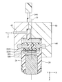
次に、図34に示されるように、このカメラモジュール(20,30)を逆さまにした状態で、専用の金型60にセットする。その後、図34の矢印Eで示すように、金型60内にホットメルト接着剤42を射出して、ホットメルト接着剤42をカメラモジュール(20,30)の内部に充填する。これにより、保持部材24と基板ユニット30との間の隙間(基板収容空間SS)がホットメルト接着剤42によって封止される。その後、常温にてホットメルト接着剤42を自然硬化する。
ホットメルト接着剤42としては、たとえば、エチレン酢酸ビニル(EVA)のような熱可塑性プラスチックを使用できるが、それには限定されない。このとき、図34に示されるように、金型60内に樹脂だまり44が形成される。
その後、図35に示されるように、ホットメルト接着剤42が充填されたカメラモジュール(20,30)から金型60を取り外して、樹脂だまり44をカットする。これにより、保持部材24の下部が封止部材40で封止される。
このようにして、図1乃至図4に示されるような、カメラ装置10が組み立てられる。
以上をまとめると、カメラ装置10の組立て方法は、上述したレンズユニット20の組立て方法に加えて更に、撮像素子(3224)を搭載したセンサ基板アセンブリ(322)を含むセンサ基板ユニット(32)を準備するセンサ基板ユニット準備工程と、電源基板アセンブリ(342)にハーネスアセンブリ(344)のケーブル(3442)をはんだ付けして、電源基板ユニット(34)を組み立てる電源基板ユニット組立て工程と、電源基板ユニット(34)とセンサ基板ユニット(32)とを基板間コネタク(3226,3424)を介して嵌合して、基板ユニット(30)を組み立てる基板ユニット組立て工程と、基板ユニット(30)を保持部材(24)中に下方から挿入して、レンズ群(22)の光軸(O)中心および合焦点位置に撮像素子(3224)の中心を合わせるように調整しながら、レンズ収容内壁面(2422a)に連通して保持部材(24)の下方に設けられた保持部材(24)の基板収容内壁面(2442a)に、基板ユニット(30)のセンサ基板ユニット(32)を固定する基板ユニット固定工程と、保持部材(24)の下部を封止部材(40)で封止する封止工程と、を更に含む。
次に、図36乃至図39を参照して、図31に示すように、基板ユニット30をレンズユニット20の保持部材24に挿入する方法について説明する。
図36はレンズユニット20の底面図であり、図37は基板ユニット30のセンサ基板ユニット32の底面図である。
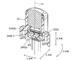
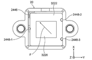
図36に示されるように、レンズユニット20の保持部材24のブラケット部244は、その下部筒状部2442-1の1つの角部で、かつ基板取付け面2442bの近傍において、基板収容内壁面2442aから内側へ突出するように形成されたL字状の突き当て部2446を有する。また、ブラケット部244は、その下部筒状部2442-1の基板収容内壁面2442aから内側へ突出する第1乃至第3の突起2448-1、2448-2、および2448-3を有する。第1の突起2448-1は、基板収容内壁面2442aの左右方向Yの左側の壁面の中央部に形成されている。第2および第3の突起2448-2および2448-3は、基板収容内壁面2442aの左右方向Yの右側の壁面の両端部側に、光軸Oを通る左右方向Yの直線に関して対称に形成されている。
図37に示されるように、基板ユニット30のセンサ基板ユニット32のセンサ基板アセンブリ322におけるセンサ基板3222は、その側面に形成された第1乃至第3のスリット3222-1、3222-2、および3222-3を持つ。第1のスリット3222-1は、センサ基板3222の左右方向Yの左側の側面の中央部に形成されている。第2および第3のスリット3222-2および3222-3は、センサ基板3222の左右方向Yの右側の側面の両端部側に、光軸Oを通る左右方向Yの直線に関して対称に形成されている。すなわち、第1乃至第3のスリット3222-1~3222-3は、それぞれ、上記第1乃至第3の突起2448-1~2448-3と対応する位置に設けられている。
このような構成を有するレンズユニット20および基板ユニット30において、基板ユニット30をレンズユニット20の保持部材24に挿入する場合、まず、図38に示されるように、レンズユニット20の保持部材24の第1乃至第3の2448-1~2448-3に、それぞれ、基板ユニット30のセンサ基板ユニット32の第1乃至第3のスリット3222-1~3222-3を通過させる。
引き続いて、図38の矢印Fで示すように、レンズユニット20に対して基板ユニット30を移動させることにより、図39に示すように、レンズユニット20の保持部材24の突き当て部2446に、センサ基板3222の角部を突き当てる。
このようにして、基板ユニット30をレンズユニット20の保持部材24に挿入する。
以上の説明から明らかなように、本発明の第1の実施形態によれば、カメラ装置10を少ない部品点数で容易に組み立てることができる。
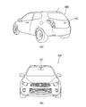
図40は、カメラ装置10を車載カメラVCとして自動車AMに取り付けた状態を示す図である。図40において、(A)は自動車AMを後面側から見た斜視図であり、(B)は自動車AMを前面側から見た正面図である。
図40(A)に示されるように、カメラ装置10は、自動車AMの車体後部にバックモニタ用カメラVCとして取り付けられる。
また、図40(B)に示されるように、カメラ装置10は、自動車AMの車体前部にフロントモニタ用カメラVCとして取り付けられる。
[第2の実施形態]
図41乃至図43を参照して、本発明の第2の実施形態に係るカメラ装置10Aの構造について説明する。図示のカメラ装置10Aも、上記第1の実施形態に係るカメラ装置10と同様に、車体後部にバックモニタ用カメラVCとして使用される車載カメラから成る。なお、カメラ装置10Aも、車体前部にフロントモニタ用カメラ等のカメラVCとして使用される車載カメラであってもよい。
図41乃至図43を参照して、本発明の第2の実施形態に係るカメラ装置10Aの構造について説明する。図示のカメラ装置10Aも、上記第1の実施形態に係るカメラ装置10と同様に、車体後部にバックモニタ用カメラVCとして使用される車載カメラから成る。なお、カメラ装置10Aも、車体前部にフロントモニタ用カメラ等のカメラVCとして使用される車載カメラであってもよい。
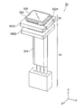
図41はカメラ装置10Aの外観斜視図である。図42は図41の線XLII-XLIIについての縦断面図である。図43は図41の線XLIII-XLIIIについての縦断面図である。
ここでは、図41乃至図43に示されるように、直交座標系(X,Y,Z)を使用している。図41乃至図43に図示した状態では、直交座標系(X,Y,Z)において、X軸方向は前後方向(奥行方向)であり、Y軸方向は左右方向(幅方向)であり、Z軸方向は上下方向(高さ方向)である。そして、図41乃至図43に示す例においては、上下方向Zがレンズの光軸O方向である。図示の例では、上下方向Zの上方向は被写体(図示せず)が存在する方向である。尚、本第2の実施形態において、Y軸方向(左右方向)は第1の方向とも呼ばれ、X軸方向(前後方向)は第2の方向とも呼ばれる。
図示のカメラ装置10Aは、レンズユニットの構成が相違するともとに、更に、別体としてブラケット70を備えている点を除いて、第1の実施形態に係るカメラ装置10と同様の構成を有する。従って、レンズユニットに20Aの参照符号を付してある。以下では、第1の実施形態に係るカメラ装置10と同様の構成要素には同一の参照符号を付して、説明の簡略化のために、それらの説明については省略する。以下では、第1の実施形態に係るカメラ装置10と相違する点についてのみ詳細に説明する。
したがって、カメラ装置10Aは、おおきく4つの構成要素から成る。すなわち、カメラ装置10Aは、レンズユニット20Aと、ブラケット70と、基板ユニット30と、封止部材40とから成る。
レンズユニット20Aは、保持部材の構成が相違する点を除いて、第1の実施形態のレンズユニット20と同様の構成を有する。したがって、保持部材に24Aの参照符号を付してある。
第1の実施形態のレンズユニット20では、保持部材24がバレル部242とブラケット部244とを一体化した構造をしている。
これに対して、本第2の実施形態のレンズユニット20Aでは、保持部材24Aがバレル242Aのみから構成されている。
第1の実施形態の保持部材24のバレル部242は、筒状部2422と、係止部2424とのみから構成されている。
これに対して、本第2の実施形態の保持部材24Aのバレル242Aは、筒状部2422および係止部2424に加えて、係止部2424から下方へ延在する四角筒形状の下部延在部2426をも更に有する。下部延在部2426の下面2426aは、基板ユニット30のセンサ基板ユニット32のセンサ基板3222を取り付けるための基板取付け面として働く。
ブラケット70は、後述するように変更されている点を除いて、第1の実施形態の保持部材24のブラケット部244と実質的に同様の構成を有する。
すなわち、第1の実施形態のブラケット部244は、筒状部2442と一対のネジ保持部2444とのみから構成されている。
これに対して、本第2の実施形態のブラケット70は、筒状部72および一対のネジ保持部74のみばかりでなく、筒状部72から上方へ延在して、保持部材24A(バレル242A)の外側壁面を覆う上部延在部76をも更に有する。各ネジ保持部74は、半円柱の外形をしており、上下方向Zに穿設されたネジ挿入穴74aを持つ。ブラケット70の筒状部72の内壁面は、基板ユニット30を収容する基板収容内壁面72aとして働く。また、ブラケット70の筒状部72は、一対の空気抜き孔72bを持つ。
レンズユニット20Aの組立て方法は、保持部材24が保持部材24Aに変更された点を除いて、前述した第1の実施形態に係るレンズユニット20の組立て方法と実質的に同じなので、詳細な説明を省略する。
したがって、レンズユニット20Aの組立て方法は、撮像素子(3224)の使用していない領域を持たない外形形状を各々持つ複数のレンズ(221~225)から成るレンズ群(22)を準備するレンズ群準備工程と、複数のレンズ(221~225)を順番に、レンズ群(22)の外形形状に合致したレンズ収容内壁面(2422a)を持つ筒状の保持部材(24A)に上方から挿入して、レンズ群(22)を保持部材(24A)内に保持するレンズ群保持工程と、保持部材(24A)の内部に水が浸入するのを防止するために、保持部材(24A)の上端に設けられたレンズ群(22)の上部レンズ(225)の上面(225a)を露出させた状態で、上部レンズ(225)の外周縁を囲むように、開口(264a)を持つリテーナ(26)を保持部材(24A)の上端に取り付けるリテーナ取付け工程と、を含む。
センサ基板ユニット32および電源基板ユニット34の組立て方法も、前述した第1の実施形態のセンサ基板ユニット32および電源基板ユニット34の組立て方法と同一であるので、それらの説明も省略する。
次に、図44乃至図46を参照して、第1のカメラモジュールの組立て方法について説明する。
先ず、図44に示されるように、センサ基板ユニット32のセンサ基板3222の表面上に、アクリル-エポキシ樹脂からなる接着剤52を塗布する。引き続いて、図44の白抜き矢印Gのように、センサ基板ユニット32を、レンズユニット20Aのバレル242Aの下端(基板取付け面)2426aへ突き合わせる。
これにより、図45に示されるように、センサ基板ユニット32を接着剤52を介してレンズユニット20Aに接着する。
この接着の際、図46に示されるように、レンズユニット20Aとセンサ基板ユニット32との光軸Oのズレを無くすように、焦点距離、回転傾きを最適な位置に調整する。換言すれば、レンズ群22の光軸O中心および合焦位置に撮像素子3224の中心を合わせるように調整する。
このように、センサ基板ユニット32のセンサ基板3222は、保持部材24Aの基板取付け面2426aに接着される。
引き続いて、上記接着箇所にUV照射して仮固定した後、オーブンにて熱硬化して、本固定を行う。
このようにして、レンズユニット20Aにセンサ基板ユニット32を固定した、第1のカメラモジュール(20A,32)が組み立てられる。
次に、図47乃至図50を参照して、ブラケット70を第1のカメラモジュール(20A,32)に取り付ける方法について説明する。
図47は、ブラケット70の平面図である。
図47に示されるように、ブラケット70は、その筒状部72の基板収容内壁面72aから内側へ突出する第1乃至第3の基板受け78-1、78-2、および78-3を有する。第1の基板受け78-1は、基板収容内壁面72aの左右方向Yの左側の壁面の中央部に形成されている。第2および第3の基板受け78-2および78-3は、基板収容内壁面72aの左右方向Yの右側の壁面の両端部側に、光軸Oを通る左右方向Yの直線に関して対称に形成されている。
図48の白抜き矢印Hで示されるように、第1のカメラモジュール(20A,32)を、ブラケット70の上方からブラケット70に挿入する。
このとき、図49に示されるように、ブラケット70の第1乃至第3の基板受け78-1~78-3まで、第1のカメラモジュール(20A,32)を差し込む。
引き続いて、図50に示されるように、ブラケット70の上部開口部周辺に、たとえば、エポキシ樹脂から成る接着剤54を塗布する。その後、オーブンにて接着剤54を硬化させる。
このようにして、ブラケット70を第1のカメラモジュール(20A,32)に取り付ける。
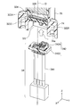
次に、図51乃至図54を参照して、ブラケット70を取り付けた第1のカメラモジュール(20A,32)に、電源基板ユニット34を取り付ける方法について説明する。
図51及び図52の白抜き矢印Iで示すように、電源基板ユニット34を下方から第1のカメラモジュール(20A,32)の基板収容空間SSへ向けて挿入する。
そして、図53及び図54に示すように、センサ基板ユニット32の第1のコネクタ(プラグコネクタ)3226と電源基板ユニット34の第2のコネクタ(レセプタクルコネクタ)3424とを嵌合する。これにより、基板ユニット32と電源基板ユニット34とが基板間コネクタ(3226,3424)を介して嵌合された基板ユニット30が組み立てられる。レンズユニット20Aとブラケット70と基板ユニット30との組み合わせは、第2のカメラモジュール(20A,70,30)と呼ばれる。
最後に、図55および図56に加えて図34および図35をも参照して、第2のカメラモジュール(20A,70,30)のブラケット70の下部を封止部材40で封止する方法について説明する。
図55に示されるように、まず、第2のカメラモジュール(20A,70,30)を逆さまにする。
次に、図34に示したのと同様に、この逆さまにした第2のカメラモジュール(20A,70,30)を専用の金型60にセットする。その後、図34の矢印Eで示すように、金型60内にホットメルト接着剤42を射出して、ホットメルト接着剤42を第2のカメラモジュール(20A,70,30)の内部に充填する。これにより、ブラケット70と基板ユニット30との間の隙間(基板収容空間SS)がホットメルト接着剤42によって封止される。その後、常温にてホットメルト接着剤42を自然硬化する。このとき、図34に示されるように、金型60内に樹脂だまり44が形成される。
その後、図35に示したのと同様に、ホットメルト接着剤42が充填された第2のカメラモジュール(20A,70,30)から金型60を取り外して、樹脂だまり44をカットする。
これにより、図56に示すように、ブラケット70の下部が封止部材40で封止される。
このようにして、図41乃至図43に示されるような、カメラ装置10Aが組み立てられる。
以上をまとめると、カメラ装置10Aの組立て方法は、上述したレンズユニット20Aの組立て方法に加えて更に、撮像素子(3224)を搭載したセンサ基板アセンブリ(322)を含むセンサ基板ユニット(32)をバレル(242A)の下端へ突合せて、レンズ群(22)の光軸(O)中心および合焦点位置に撮像素子(3224)の中心を合わせるように調整しながら、バレル(242A)の下端にセンサ基板ユニット(32)を固定して、カメラモジュール(20A,32)を組み立てるモジュール組立て工程と、当該カメラ装置を他の装置へ取り付けるためのブラケット(70)に、カメラモジュール(20A,32)を差し込んで取り付けるモジュール取付け工程と、電源基板アセンブリ(342)にハーネスアセンブリ(344)のケーブル(3442)をはんだ付けして、電源基板ユニット(34)を組み立てる電源基板ユニット組立て工程と、電源基板ユニット(34)とセンサ基板ユニット(32)とを基板間コネタク(3226,3424)を介して嵌合して、基板ユニット(30)を組み立てるユニット組立て工程と、ブラケット(70)の下部を封止部材(40)で封止する封止工程と、を含む。
以上の説明から明らかなように、本発明の第2の実施形態によれば、上述した第1の実施形態に係るカメラ装置10と比較して、カメラ装置10Aをより容易に組み立てることが可能となる。
その理由は、次の通りである。本発明の第2の実施形態に係るカメラ装置10Aでは、バレル242Aとブラケット70とを分離したので、第1の実施形態のカメラ装置10よりも部品点数が増えてしまう。しかしながら、第1の実施形態のカメラ装置10では、保持部材24をバレル部242とブラケット部244とを一体化して構成したことにより、保持部材24に機能を盛り込み過ぎることになる。これに対して、本発明の第2の実施形態では、バレル242Aとブラケット70とを分離したので、第1の実施形態における保持部材24の機能も分離することが可能となり、より組み立て易くなるからである。
本発明の例示的な態様について説明する。
本発明の第1の例示的な態様によれば、カメラ装置(10;10A)の組立て方法であって、撮像素子(3224)の使用していない領域を持たない外形形状を各々持つ複数のレンズ(221~225)から成るレンズ群(22)を準備するレンズ群準備工程と、複数のレンズ(221~225)を順番に、レンズ群(22)の外形形状に合致したレンズ収容内壁面(2422a)を持つ筒状の保持部材(24;24A)に上方から挿入して、レンズ群(22)を保持部材(24;24A)内に保持するレンズ群保持工程と、保持部材(24;24A)の上端に設けられたレンズ群(22)の上部レンズ(225)の上面(225a)を露出させた状態で、上部レンズ(225)の外周縁を囲むように、開口(264a)を持つリテーナ(26)を保持部材(24;24A)の上端に取り付けるリテーナ取付け工程と、を含むカメラ装置の組立て方法が得られる。
上記カメラ装置(10;10A)の組立て方法において、上記レンズ群(22)の外形形状は矩形であることが好ましい。上記リテーナ取付け工程は、リテーナ(26)を保持部材(24;24A)の上端に接着剤(52)で固定して取り付ける工程であってよい。
また、上記カメラ装置(10)の組立て方法において、保持部材(24)は、レンズ群(22)を遮光するバレル部(242)と、当該カメラ装置(10)を他の装置へ取付けるブラケット部(244)とを含み、バレル部(242)とブラケット部(244)とが一体となった構造をしていてよい。
この場合、上記カメラ装置(10)の組立て方法は、撮像素子(3224)を搭載したセンサ基板アセンブリ(322)を含むセンサ基板ユニット(32)を準備するセンサ基板ユニット準備工程と、電源基板アセンブリ(342)にハーネスアセンブリ(344)を取付けて、電源基板ユニット(34)を組み立てる電源基板ユニット組立て工程と、電源基板ユニット(34)とセンサ基板ユニット(32)と接合して、基板ユニット(30)を組み立てる基板ユニット組立て工程と、基板ユニット(30)を保持部材(24)中に下方から挿入して、レンズ群(22)の光軸(O)中心および合焦点位置に撮像素子(3224)の中心を合わせるように調整しながら、レンズ収容内壁面(2422a)に連通して保持部材(24)の下方に設けられた保持部材(24)の基板収容内壁面(2442a)に、基板ユニット(30)のセンサ基板ユニット(32)を固定する基板ユニット固定工程と、保持部材(24)の下部を封止部材(40)で封止する封止工程と、を更に含んでよい。上記基板ユニット固定工程は、センサ基板ユニット(32)を接着剤(52)で保持部材(24)の基板収容内壁面(2442a)に固定する工程であってよい。上記封止工程は、保持部材(24)の下部に接着剤(42)を充填して、保持部材(24)と基板ユニット(30)との間の隙間(SS)を封止部材(40)で封止する工程であってよい。
その代わりに、上記カメラ装置(10A)の組立て方法において、保持部材(24A)は、レンズ群(22)を遮光するバレル(242A)から構成されてよい。
この場合、上記カメラ装置(10A)の組立て方法は、撮像素子(3224)を搭載したセンサ基板アセンブリ(322)を含むセンサ基板ユニット(32)をバレル(242A)の下端へ突合せて、レンズ群(22)の光軸(O)中心および合焦点位置に撮像素子(3224)の中心を合わせるように調整しながら、バレル(242A)の下端にセンサ基板ユニット(32)を固定して、カメラモジュール(20A;32)を組み立てるモジュール組立て工程と、当該カメラ装置(10A)を他の装置へ取り付けるブラケット(70)に、カメラモジュール(20A;32)を差し込んで取り付けるモジュール取付け工程と、電源基板アセンブリ(342)にハーネスアセンブリ(344)を取付けて、電源基板ユニット(34)を組み立てる電源基板ユニット組立て工程と、電源基板ユニット(34)とセンサ基板ユニット(32)とを接合して、基板ユニット(30)を組み立てるユニット組立て工程と、ブラケット(70)の下部を封止部材(40)で封止する封止工程と、を更に含んでよい。上記モジュール組立て工程は、センサ基板ユニット(32)を接着剤(52)でバレル(242A)の下端に固定する工程であってよい。上記封止工程は、ブラケット(242A)の下部に接着剤(42)を充填して、ブラケット(242A)と基板ユニット(30)との間の隙間(SS)を封止部材(40)で封止する工程であってよい。
上記カメラ装置(10;10A)の組立て方法において、カメラ装置(10;10A)が車体に搭載される車載カメラから構成されてよい。
本発明の第2の例示的な態様によれば、カメラ装置(10;10A)に使用されるレンズユニット(20;20A)の組立て方法であって、撮像素子(3224)の使用していない領域を持たない外形形状を各々持つ複数のレンズ(221~225)から成るレンズ群(22)を準備するレンズ群準備工程と、複数のレンズ(221~225)を順番に、レンズ群(22)の外形形状に合致したレンズ収容内壁面(2422a)を持つ筒状の保持部材(24;24A)に上方から挿入して、レンズ群(22)を保持部材(24;24A)内に保持するレンズ群保持工程と、保持部材(24;24A)の上端に設けられたレンズ群(22)の上部レンズ(225)の上面(225a)を露出させた状態で、上部レンズ(225)の外周縁を囲むように、開口(264a)を持つリテーナ(26)を保持部材(24;24A)の上端に取り付けるリテーナ取付け工程と、を含むレンズユニットの組立て方法が得られる。
上記レンズユニット(20;20A)の組立て方法において、レンズ群(22)の外形形状は矩形であることが好ましい。上記リテーナ取付け工程は、リテーナ(26)を保持部材(24;24A)の上端に接着剤で固定して取り付ける工程であってよい。
なお、上記保持部材(24)は、レンズ群(22)を遮光するバレル部(242)と、当該カメラ装置(10)を他の装置へ取付けるブラケット部(244)とを含み、バレル部(242)とブラケット部(244)とが一体となった構造をしていてよい。
その代わりに、上記保持部材(24A)は、レンズ群(22)を遮光するバレル(242A)から構成されてよい。
尚、上記括弧内の参照符号は、本発明の理解を容易にするために付したものであり、一例に過ぎず、本発明は、これらに限定されないのは勿論である。
以上、実施の形態を参照して本発明を説明したが、本発明は上記実施の形態に限定されるものではない。本発明の構成や詳細には、本発明のスコープ内で当業者が理解し得る様々な変更をすることができる。
例えば、上述した実施形態では、保持部材(ブラケット)の下部に対する封止部材による封止を、ホットメルト接着剤を充填することによって行っているが、これに限定されず、他の封止方法を採用してもよい。
本発明に係るカメラ装置は、車載カメラには限定されず、他の分野(例えば、医療分野)に使用されるカメラとしても利用されえる。
この出願は、2015年4月27日に出願された日本出願特願2015-090377号を基礎とする優先権を主張し、その開示の全てをここに取り込む。
10 カメラ装置(車載カメラ)
10A カメラ装置(車載カメラ)
20 レンズユニット
20A レンズユニット
22 レンズ群
221 第1のレンズ
222 第2のレンズ
223 第3のレンズ
224 第4のレンズ(下部レンズ)
225 第5のレンズ(上部レンズ)
225a 上面
24 保持部材
24A 保持部材
242 バレル部
242A バレル
2422 筒状部
2422a レンズ収容内壁面
2422b リテーナ受け面
2424 係止部
2424a 係止面
2426 下部延在部
2426a 基板取付け面
244 ブラケット部
2442 筒状部
2442-1 下部筒状部
2442-2 上部筒状部
2442a 基板収容内壁面
2442b 基板取付け面
2442c 空気抜き孔
2444 ネジ保持部
2444a ネジ挿入穴
2446 突き当て部
2448-1 第1の突起
2448-2 第2の突起
2448-3 第3の突起
26 リテーナ
262 外筒部
264 上端部
264a 開口
30 基板ユニット(PWBユニット)
32 センサ基板ユニット(センサPWBユニット)
322 センサ基板アセンブリ(センサPWBアセンブリ)
3222 センサ基板
3222-1 第1のスリット
3222-2 第2のスリット
3222-3 第3のスリット
3224 撮像素子
3226 第1のコネクタ(センサ側コネクタ;プラグコネクタ)
324 粘着テープ
326 赤外線カットフィルタ(IRCF)
34 電源基板ユニット(電源PWBユニット)
342 電源基板アセンブリ(電源PWBアセンブリ)
3422 電源基板(電源PWB)
3424 第2のコネクタ(電源側コネクタ;レセプタクルコネクタ)
344 ハーネスアセンブリ
3442 ケーブル(電線)
40 封止部材
42 接着剤(ホットメルト接着剤)
44 樹脂だまり
52 接着剤
54 接着剤
60 金型
70 ブラケット
72 筒状部
72a 基板収容内壁面
72b 空気抜き孔
74 ネジ保持部
74a ネジ挿入穴
76 上部延在部
78-1 第1の基板受け
78-2 第2の基板受け
78-3 第3の基板受け
LS レンズ収容空間
SS 基板収容空間
AM 自動車
VC 車載カメラ
O 光軸
X 前後方向(第2の方向)
Y 左右方向(第1の方向)
Z 上下方向
10A カメラ装置(車載カメラ)
20 レンズユニット
20A レンズユニット
22 レンズ群
221 第1のレンズ
222 第2のレンズ
223 第3のレンズ
224 第4のレンズ(下部レンズ)
225 第5のレンズ(上部レンズ)
225a 上面
24 保持部材
24A 保持部材
242 バレル部
242A バレル
2422 筒状部
2422a レンズ収容内壁面
2422b リテーナ受け面
2424 係止部
2424a 係止面
2426 下部延在部
2426a 基板取付け面
244 ブラケット部
2442 筒状部
2442-1 下部筒状部
2442-2 上部筒状部
2442a 基板収容内壁面
2442b 基板取付け面
2442c 空気抜き孔
2444 ネジ保持部
2444a ネジ挿入穴
2446 突き当て部
2448-1 第1の突起
2448-2 第2の突起
2448-3 第3の突起
26 リテーナ
262 外筒部
264 上端部
264a 開口
30 基板ユニット(PWBユニット)
32 センサ基板ユニット(センサPWBユニット)
322 センサ基板アセンブリ(センサPWBアセンブリ)
3222 センサ基板
3222-1 第1のスリット
3222-2 第2のスリット
3222-3 第3のスリット
3224 撮像素子
3226 第1のコネクタ(センサ側コネクタ;プラグコネクタ)
324 粘着テープ
326 赤外線カットフィルタ(IRCF)
34 電源基板ユニット(電源PWBユニット)
342 電源基板アセンブリ(電源PWBアセンブリ)
3422 電源基板(電源PWB)
3424 第2のコネクタ(電源側コネクタ;レセプタクルコネクタ)
344 ハーネスアセンブリ
3442 ケーブル(電線)
40 封止部材
42 接着剤(ホットメルト接着剤)
44 樹脂だまり
52 接着剤
54 接着剤
60 金型
70 ブラケット
72 筒状部
72a 基板収容内壁面
72b 空気抜き孔
74 ネジ保持部
74a ネジ挿入穴
76 上部延在部
78-1 第1の基板受け
78-2 第2の基板受け
78-3 第3の基板受け
LS レンズ収容空間
SS 基板収容空間
AM 自動車
VC 車載カメラ
O 光軸
X 前後方向(第2の方向)
Y 左右方向(第1の方向)
Z 上下方向
Claims (15)
- カメラ装置(10;10A)の組立て方法であって、
撮像素子(3224)の使用していない領域を持たない外形形状を各々持つ複数のレンズ(221~225)から成るレンズ群(22)を準備するレンズ群準備工程と、
前記複数のレンズ(221~225)を順番に、前記レンズ群(22)の外形形状に合致したレンズ収容内壁面(2422a)を持つ筒状の保持部材(24;24A)に上方から挿入して、前記レンズ群(22)を前記保持部材(24;24A)内に保持するレンズ群保持工程と、
前記保持部材(24;24A)の上端に設けられた前記レンズ群(22)の上部レンズ(225)の上面(225a)を露出させた状態で、前記上部レンズ(225)の外周縁を囲むように、開口(264a)を持つリテーナ(26)を前記保持部材(24;24A)の上端に取り付けるリテーナ取付け工程と、
を含むカメラ装置の組立て方法。 - 前記レンズ群(22)の外形形状が矩形である、請求項1に記載のカメラ装置の組立て方法。
- 前記リテーナ取付け工程は、前記リテーナ(26)を前記保持部材(24;24A)の上端に接着剤(52)で固定して取り付ける工程である、請求項1又は2に記載のカメラ装置の組立て方法。
- 前記保持部材(24)は、前記レンズ群(22)を遮光するバレル部(242)と、当該カメラ装置(10)を他の装置へ取付けるブラケット部(244)とを含み、前記バレル部(242)と前記ブラケット部(244)とが一体となった構造をしており、
前記撮像素子(3224)を搭載したセンサ基板アセンブリ(322)を含むセンサ基板ユニット(32)を準備するセンサ基板ユニット準備工程と、
電源基板アセンブリ(342)にハーネスアセンブリ(344)を取付けて、電源基板ユニット(34)を組み立てる電源基板ユニット組立て工程と、
前記電源基板ユニット(34)と前記センサ基板ユニット(32)とを接合して、基板ユニット(30)を組み立てる基板ユニット組立て工程と、
前記基板ユニット(30)を前記保持部材(24)中に下方から挿入して、前記レンズ群(22)の光軸(O)中心および合焦点位置に前記撮像素子(3224)の中心を合わせるように調整しながら、前記レンズ収容内壁面(3422a)に連通して前記保持部材(24)の下方に設けられた前記保持部材(24)の基板収容内壁面(2442a)に、前記基板ユニット(30)の前記センサ基板ユニット(32)を固定する基板ユニット固定工程と、
前記保持部材(24)の下部を封止部材(40)で封止する封止工程と、
を更に含む請求項1乃至3のいずれか1項に記載のカメラ装置の組立て方法。 - 前記基板ユニット固定工程は、前記センサ基板ユニット(32)を接着剤(52)で前記保持部材(24)の基板収容内壁面(2442a)に固定する工程である、請求項4に記載のカメラ装置の組立て方法。
- 前記封止工程は、前記保持部材(24)の下部に接着剤(42)を充填して、前記保持部材(24)と前記基板ユニット(30)との間の隙間(SS)を前記封止部材(40)で封止する工程である、請求項4又は5に記載のカメラ装置の組立て方法。
- 前記保持部材(24A)は、前記レンズ群(22)を遮光するバレル(242A)から成り、
前記撮像素子(3224)を搭載したセンサ基板アセンブリ(322)を含むセンサ基板ユニット(32)を前記バレル(242A)の下端へ突合せて、前記レンズ群(22)の光軸(O)中心および合焦点位置に前記撮像素子(3224)の中心を合わせるように調整しながら、前記バレル(242A)の下端に前記センサ基板ユニット(32)を固定して、カメラモジュール(20A,32)を組み立てるモジュール組立て工程と、
当該カメラ装置(10A)を他の装置へ取り付けるブラケット(70)に、前記カメラモジュール(20A,32)を差し込んで取り付けるモジュール取付け工程と、
電源基板アセンブリ(342)にハーネスアセンブリ(344)を取付けて、電源基板ユニット(34)を組み立てる電源基板ユニット組立て工程と、
前記電源基板ユニット(34)と前記センサ基板ユニット(32)とを接合して、基板ユニット(30)を組み立てるユニット組立て工程と、
前記ブラケット(70)の下部を封止部材(40)で封止する封止工程と、
を更に含む請求項1乃至3のいずれか1項に記載のカメラ装置の組立て方法。 - 前記モジュール組立て工程は、前記センサ基板ユニット(32)を接着剤(52)で前記バレル(242A)の下端に固定する工程である、請求項7に記載のカメラ装置の組立て方法。
- 前記封止工程は、前記ブラケット(242A)の下部に接着剤(42)を充填して、前記ブラケット(242A)と前記基板ユニット(30)との間の隙間(SS)を前記封止部材(40)で封止する工程である、請求項7又は8に記載のカメラ装置の組立て方法。
- 前記カメラ装置(10;10A)が車体に搭載される車載カメラから成る、請求項1乃至9のいずれか1つに記載のカメラ装置の組立て方法。
- カメラ装置(10;10A)に使用されるレンズユニット(20;20A)の組立て方法であって、
撮像素子(3224)の使用していない領域を持たない外形形状を各々持つ複数のレンズ(221~225)から成るレンズ群(22)を準備するレンズ群準備工程と、
前記複数のレンズ(221~225)を順番に、前記レンズ群(22)の外形形状に合致したレンズ収容内壁面(2422a)を持つ筒状の保持部材(24;24A)に上方から挿入して、前記レンズ群(22)を前記保持部材(24;24A)内に保持するレンズ群保持工程と、
前記保持部材(24;24A)の上端に設けられた前記レンズ群(22)の上部レンズ(225)の上面(225a)を露出させた状態で、前記上部レンズ(225)の外周縁を囲むように、開口(264a)を持つリテーナ(26)を前記保持部材(24;24A)の上端に取り付けるリテーナ取付け工程と、
を含むレンズユニットの組立て方法。 - 前記レンズ群(22)の外形形状が矩形である、請求項11に記載のレンズユニットの組立て方法。
- 前記リテーナ取付け工程は、前記リテーナ(26)を前記保持部材(24;24A)の上端に接着剤で固定して取り付ける工程である、請求項11又は12に記載のレンズユニットの組立て方法。
- 前記保持部材(24)は、前記レンズ群(22)を遮光するバレル部(242)と、当該カメラ装置(10)を他の装置へ取付けるブラケット部(244)とを含み、前記バレル部(242)と前記ブラケット部(244)とが一体となった構造をしている、請求項11乃至13のいずれか1項に記載のレンズユニットの組立て方法。
- 前記保持部材(24A)は、前記レンズ群(22)を遮光するバレル(242A)から成る、請求項11乃至13のいずれか1項に記載のレンズユニットの組立て方法。
Priority Applications (1)
| Application Number | Priority Date | Filing Date | Title |
|---|---|---|---|
| US15/569,796 US10288831B2 (en) | 2015-04-27 | 2016-04-26 | Method for assembling camera device and method for assembling lens unit |
Applications Claiming Priority (2)
| Application Number | Priority Date | Filing Date | Title |
|---|---|---|---|
| JP2015-090377 | 2015-04-27 | ||
| JP2015090377A JP6583611B2 (ja) | 2015-04-27 | 2015-04-27 | カメラ装置の組立て方法およびレンズユニットの組立て方法 |
Publications (1)
| Publication Number | Publication Date |
|---|---|
| WO2016175198A1 true WO2016175198A1 (ja) | 2016-11-03 |
Family
ID=57199166
Family Applications (1)
| Application Number | Title | Priority Date | Filing Date |
|---|---|---|---|
| PCT/JP2016/063025 Ceased WO2016175198A1 (ja) | 2015-04-27 | 2016-04-26 | カメラ装置の組立て方法およびレンズユニットの組立て方法 |
Country Status (3)
| Country | Link |
|---|---|
| US (1) | US10288831B2 (ja) |
| JP (1) | JP6583611B2 (ja) |
| WO (1) | WO2016175198A1 (ja) |
Families Citing this family (11)
| Publication number | Priority date | Publication date | Assignee | Title |
|---|---|---|---|---|
| DE102016208549A1 (de) * | 2016-05-18 | 2017-11-23 | Robert Bosch Gmbh | Kameramodul für ein Fahrzeug |
| US10694153B2 (en) * | 2016-09-23 | 2020-06-23 | Gentex Corporation | Imager with wire harness connecting features |
| KR102371355B1 (ko) * | 2017-08-11 | 2022-03-07 | 엘지이노텍 주식회사 | 차량용 카메라 |
| JP2019213083A (ja) * | 2018-06-06 | 2019-12-12 | 株式会社リコー | 撮像光学系、撮像装置及び撮像システム |
| JP7103601B2 (ja) * | 2018-10-19 | 2022-07-20 | 株式会社東海理化電機製作所 | カメラ装置 |
| US20200236256A1 (en) * | 2019-04-12 | 2020-07-23 | Luxvisions Innovation Limited | Camera assembly and mobile device having the same |
| TWI791962B (zh) * | 2019-04-24 | 2023-02-11 | 大陸商信泰光學(深圳)有限公司 | 鏡頭裝置 |
| CN210007739U (zh) * | 2019-06-28 | 2020-01-31 | 三赢科技(深圳)有限公司 | 镜头模组及电子装置 |
| JP2022120272A (ja) * | 2021-02-05 | 2022-08-18 | 株式会社リコー | レンズユニット、光学系及び電子機器 |
| TWI855465B (zh) * | 2022-12-21 | 2024-09-11 | 海華科技股份有限公司 | 影像感測鏡頭及外封閉式感測模組 |
| US12377793B2 (en) * | 2023-08-16 | 2025-08-05 | Honda Motor Co., Ltd. | Center camera mirror system spoiler mounting for vehicle, and tailgate assembly including same |
Citations (5)
| Publication number | Priority date | Publication date | Assignee | Title |
|---|---|---|---|---|
| JP2002252796A (ja) * | 2001-02-26 | 2002-09-06 | Mitsubishi Electric Corp | 撮像装置 |
| JP2007053144A (ja) * | 2005-08-15 | 2007-03-01 | Fujifilm Corp | 電子機器、および撮影装置 |
| WO2012039304A1 (ja) * | 2010-09-22 | 2012-03-29 | コニカミノルタオプト株式会社 | 撮像レンズユニットの製造方法、及び、撮像レンズユニット |
| WO2012043195A1 (ja) * | 2010-09-30 | 2012-04-05 | コニカミノルタオプト株式会社 | 撮像レンズユニットの製造方法、及び、撮像レンズユニット |
| JP2013228610A (ja) * | 2012-04-26 | 2013-11-07 | Panasonic Corp | カメラモジュール |
Family Cites Families (10)
| Publication number | Priority date | Publication date | Assignee | Title |
|---|---|---|---|---|
| JPS52108026U (ja) | 1976-02-12 | 1977-08-17 | ||
| JP3138191B2 (ja) * | 1995-08-10 | 2001-02-26 | 三洋電機株式会社 | 固体撮像素子 |
| JP2000056221A (ja) | 1998-08-07 | 2000-02-25 | Minolta Co Ltd | ズームレンズ装置 |
| JP2008177871A (ja) | 2007-01-18 | 2008-07-31 | Smk Corp | モジュール機器用電気機器 |
| CN101681085B (zh) * | 2007-04-24 | 2014-11-19 | 数字光学公司 | 采用晶片级光学系统的自动聚焦/变焦模块 |
| JP2009113736A (ja) * | 2007-11-09 | 2009-05-28 | Sony Corp | カメラ取り付け構造、カメラ取り付け方法および車両の外装パネル部品 |
| JP2009194543A (ja) * | 2008-02-13 | 2009-08-27 | Panasonic Corp | 撮像装置およびその製造方法 |
| CN102326382B (zh) * | 2010-03-10 | 2016-04-13 | Smk株式会社 | 摄像机模块 |
| JP2012183925A (ja) | 2011-03-07 | 2012-09-27 | Panasonic Corp | 車載カメラ |
| US10101555B2 (en) * | 2013-07-17 | 2018-10-16 | Heptagon Micro Optics Pte. Ltd. | Camera module including a non-circular lens |
-
2015
- 2015-04-27 JP JP2015090377A patent/JP6583611B2/ja not_active Expired - Fee Related
-
2016
- 2016-04-26 US US15/569,796 patent/US10288831B2/en not_active Expired - Fee Related
- 2016-04-26 WO PCT/JP2016/063025 patent/WO2016175198A1/ja not_active Ceased
Patent Citations (5)
| Publication number | Priority date | Publication date | Assignee | Title |
|---|---|---|---|---|
| JP2002252796A (ja) * | 2001-02-26 | 2002-09-06 | Mitsubishi Electric Corp | 撮像装置 |
| JP2007053144A (ja) * | 2005-08-15 | 2007-03-01 | Fujifilm Corp | 電子機器、および撮影装置 |
| WO2012039304A1 (ja) * | 2010-09-22 | 2012-03-29 | コニカミノルタオプト株式会社 | 撮像レンズユニットの製造方法、及び、撮像レンズユニット |
| WO2012043195A1 (ja) * | 2010-09-30 | 2012-04-05 | コニカミノルタオプト株式会社 | 撮像レンズユニットの製造方法、及び、撮像レンズユニット |
| JP2013228610A (ja) * | 2012-04-26 | 2013-11-07 | Panasonic Corp | カメラモジュール |
Also Published As
| Publication number | Publication date |
|---|---|
| JP2016206536A (ja) | 2016-12-08 |
| US10288831B2 (en) | 2019-05-14 |
| JP6583611B2 (ja) | 2019-10-02 |
| US20180143395A1 (en) | 2018-05-24 |
Similar Documents
| Publication | Publication Date | Title |
|---|---|---|
| JP6583611B2 (ja) | カメラ装置の組立て方法およびレンズユニットの組立て方法 | |
| KR102708474B1 (ko) | 카메라 모듈 | |
| US10694090B2 (en) | Method of forming camera module for vehicular vision system | |
| JP7178993B2 (ja) | カメラモジュール及びカメラモジュール製造方法 | |
| US10205865B2 (en) | Camera and method for manufacturing the same | |
| CN207491066U (zh) | 双摄像模组及其感光组件和电子设备 | |
| CN206212113U (zh) | 阵列摄像模组和双摄像模组及其线路板组件和电子设备 | |
| KR102550823B1 (ko) | 카메라 모듈 | |
| US20090244361A1 (en) | Camera module for vehicle vision system | |
| WO2017140118A1 (zh) | 阵列摄像模组及其模塑感光组件、线路板组件和制造方法以及电子设备 | |
| KR102500655B1 (ko) | 카메라 모듈 및 이를 포함하는 자동차 | |
| US7679156B2 (en) | Optical module and optical system | |
| TWM587609U (zh) | 車用攝像模組 | |
| TW201741752A (zh) | 陣列攝像模組及其模塑感光組件、線路板組件和製造方法以及電子設備 | |
| TW201933686A (zh) | 連接器、連接器組件及連接器組件的組裝方法 | |
| KR20170108668A (ko) | 렌즈 배럴 어셈블리 및 이를 포함하는 렌즈 모듈 | |
| KR20250040916A (ko) | 카메라 | |
| JP5999378B2 (ja) | カメラモジュール | |
| JP5821394B2 (ja) | 撮像装置 | |
| KR102358698B1 (ko) | 카메라 모듈 및 자동차 | |
| JP2007004068A (ja) | カメラモジュールの製造方法及びカメラモジュール | |
| KR102415400B1 (ko) | 카메라 모듈 및 자동차 | |
| JP2012083556A (ja) | カメラモジュール | |
| KR102411132B1 (ko) | 카메라 모듈 | |
| CN210041984U (zh) | 车用摄像模块 |
Legal Events
| Date | Code | Title | Description |
|---|---|---|---|
| 121 | Ep: the epo has been informed by wipo that ep was designated in this application |
Ref document number: 16786475 Country of ref document: EP Kind code of ref document: A1 |
|
| WWE | Wipo information: entry into national phase |
Ref document number: 15569796 Country of ref document: US |
|
| NENP | Non-entry into the national phase |
Ref country code: DE |
|
| 122 | Ep: pct application non-entry in european phase |
Ref document number: 16786475 Country of ref document: EP Kind code of ref document: A1 |