WO2016174826A1 - 熱交換器およびそれを用いた冷凍サイクル装置 - Google Patents
熱交換器およびそれを用いた冷凍サイクル装置 Download PDFInfo
- Publication number
- WO2016174826A1 WO2016174826A1 PCT/JP2016/001909 JP2016001909W WO2016174826A1 WO 2016174826 A1 WO2016174826 A1 WO 2016174826A1 JP 2016001909 W JP2016001909 W JP 2016001909W WO 2016174826 A1 WO2016174826 A1 WO 2016174826A1
- Authority
- WO
- WIPO (PCT)
- Prior art keywords
- heat exchanger
- water
- insert
- pipe
- inner pipe
- Prior art date
Links
Images


Classifications
-
- F—MECHANICAL ENGINEERING; LIGHTING; HEATING; WEAPONS; BLASTING
- F28—HEAT EXCHANGE IN GENERAL
- F28F—DETAILS OF HEAT-EXCHANGE AND HEAT-TRANSFER APPARATUS, OF GENERAL APPLICATION
- F28F13/00—Arrangements for modifying heat-transfer, e.g. increasing, decreasing
- F28F13/06—Arrangements for modifying heat-transfer, e.g. increasing, decreasing by affecting the pattern of flow of the heat-exchange media
- F28F13/12—Arrangements for modifying heat-transfer, e.g. increasing, decreasing by affecting the pattern of flow of the heat-exchange media by creating turbulence, e.g. by stirring, by increasing the force of circulation
-
- F—MECHANICAL ENGINEERING; LIGHTING; HEATING; WEAPONS; BLASTING
- F24—HEATING; RANGES; VENTILATING
- F24H—FLUID HEATERS, e.g. WATER OR AIR HEATERS, HAVING HEAT-GENERATING MEANS, e.g. HEAT PUMPS, IN GENERAL
- F24H9/00—Details
-
- F—MECHANICAL ENGINEERING; LIGHTING; HEATING; WEAPONS; BLASTING
- F28—HEAT EXCHANGE IN GENERAL
- F28D—HEAT-EXCHANGE APPARATUS, NOT PROVIDED FOR IN ANOTHER SUBCLASS, IN WHICH THE HEAT-EXCHANGE MEDIA DO NOT COME INTO DIRECT CONTACT
- F28D7/00—Heat-exchange apparatus having stationary tubular conduit assemblies for both heat-exchange media, the media being in contact with different sides of a conduit wall
- F28D7/02—Heat-exchange apparatus having stationary tubular conduit assemblies for both heat-exchange media, the media being in contact with different sides of a conduit wall the conduits being helically coiled
-
- F—MECHANICAL ENGINEERING; LIGHTING; HEATING; WEAPONS; BLASTING
- F28—HEAT EXCHANGE IN GENERAL
- F28D—HEAT-EXCHANGE APPARATUS, NOT PROVIDED FOR IN ANOTHER SUBCLASS, IN WHICH THE HEAT-EXCHANGE MEDIA DO NOT COME INTO DIRECT CONTACT
- F28D7/00—Heat-exchange apparatus having stationary tubular conduit assemblies for both heat-exchange media, the media being in contact with different sides of a conduit wall
- F28D7/04—Heat-exchange apparatus having stationary tubular conduit assemblies for both heat-exchange media, the media being in contact with different sides of a conduit wall the conduits being spirally coiled
-
- F—MECHANICAL ENGINEERING; LIGHTING; HEATING; WEAPONS; BLASTING
- F28—HEAT EXCHANGE IN GENERAL
- F28D—HEAT-EXCHANGE APPARATUS, NOT PROVIDED FOR IN ANOTHER SUBCLASS, IN WHICH THE HEAT-EXCHANGE MEDIA DO NOT COME INTO DIRECT CONTACT
- F28D7/00—Heat-exchange apparatus having stationary tubular conduit assemblies for both heat-exchange media, the media being in contact with different sides of a conduit wall
- F28D7/10—Heat-exchange apparatus having stationary tubular conduit assemblies for both heat-exchange media, the media being in contact with different sides of a conduit wall the conduits being arranged one within the other, e.g. concentrically
- F28D7/106—Heat-exchange apparatus having stationary tubular conduit assemblies for both heat-exchange media, the media being in contact with different sides of a conduit wall the conduits being arranged one within the other, e.g. concentrically consisting of two coaxial conduits or modules of two coaxial conduits
-
- F—MECHANICAL ENGINEERING; LIGHTING; HEATING; WEAPONS; BLASTING
- F28—HEAT EXCHANGE IN GENERAL
- F28F—DETAILS OF HEAT-EXCHANGE AND HEAT-TRANSFER APPARATUS, OF GENERAL APPLICATION
- F28F21/00—Constructions of heat-exchange apparatus characterised by the selection of particular materials
- F28F21/06—Constructions of heat-exchange apparatus characterised by the selection of particular materials of plastics material
Definitions
- the present invention relates to a heat exchanger that exchanges heat between fluids.
- a heat pump water heater equipped with this type of heat exchanger is a device that uses a certain amount of time at night mainly to boil hot water, and during boiling operation, the flow velocity of water flowing through the heat exchanger of the same water heater. Is relatively small.
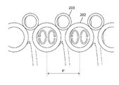
- FIG. 11 is a schematic view (partially sectional view) of the conventional heat exchanger described in Patent Document 1. As shown in FIG. FIG. 12 is an enlarged view showing a cross section of the heat exchanger of FIG.
- the heat exchanger 201 includes a water pipe 202 and one or more refrigerant pipes 203 for one water pipe 202.
- the water tube 202 is formed in a substantially cylindrical shape by being spirally wound.
- the refrigerant pipe 203 is spirally wound at a predetermined pitch on the outer periphery of a water pipe 202 formed in a substantially cylindrical shape. Further, at least one or more of the refrigerant pipes 203 are joined along substantially the entire length of the water pipe 202.
- the flow direction of the water flowing through the water pipe 202 and the flow direction of the refrigerant flowing inside the refrigerant pipe 203 are opposite to each other.
- the temperature field in the cross section perpendicular to the main flow is improved by the secondary flow, so it is significantly larger than a straight tubular heat exchanger in which the water pipe and the refrigerant pipe are joined. Heat transfer performance can be improved.
- FIG. 13 is a schematic view of a conventional heat exchanger described in Patent Document 2. As shown in FIG. 13
- the heat exchanger 301 includes a water pipe 302 having a straight portion, and one or more refrigerant pipes 303 for one water pipe 302.
- the refrigerant pipe 303 is wound around the water pipe 302, and a twist tape is inserted into the water pipe 302 as heat transfer promoting means.
- the water pipe since the heat exchanger is formed by spirally winding the pipe, the water pipe may be flattened or the seat may be depending on the pipe material and the pipe diameter and thickness. There is a possibility of yielding.
- the present invention solves the above-mentioned conventional problems, and an object of the present invention is to provide a heat exchanger which is compact and excellent in economy, and has high quality performance and heat exchange performance.
- the heat exchanger of the present invention includes an inner pipe through which the first fluid flows, an insert inserted into the inner pipe, and an outer pipe which is provided on the outer periphery of the inner pipe and through which the second fluid flows. And have.
- the insert comprises a shank and a helical projection formed on the outer surface of the shank.
- the first fluid flows in a spiral flow path formed by the inner surface of the inner pipe, the shaft portion and the spiral projection.
- the spiral flow passage through which the first fluid flows can be formed by two parts of the inner pipe and the insert having the spiral projection, it is not necessary to wind the inner pipe for forming the flow passage. Therefore, since the inner pipe is not buckled or flattened, the wall thickness of the pipe can be minimized, and a lightweight heat exchanger excellent in economy can be provided.
- the radius of curvature of the spiral flow passage can be set smaller than in the prior art, the heat transfer promotion effect by the secondary flow can be large, and a compact heat exchanger can be provided.
- the longest distance from the heat transfer surface of the first fluid is determined by the axial diameter of the insert and the height of the projection of the helical projection.
- the pitch of the helical projections can be changed so that the flow path cross-sectional area becomes a water pressure loss acceptable to the water transfer pump. Therefore, it is possible to provide a heat exchanger with high heat exchange performance in which the dead area is greatly reduced within the water pressure loss restriction range.
- FIG. 1 is a schematic view of a heat exchanger according to Embodiment 1 of the present invention.
- FIG. 2A is a perspective view showing the flow of fluid in the outer tube of the heat exchanger in Embodiment 1 of the present invention.
- FIG. 2B is a perspective view showing the flow of fluid in the inner pipe of the heat exchanger.
- FIG. 3 is an enlarged view of part A of FIG.
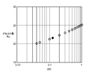
- FIG. 4 is a figure which shows the trial calculation result of the heat transfer coefficient in the same spiral circular pipe.
- FIG. 5A is an external view of an insert of a heat exchanger according to Embodiment 2 of the present invention.
- FIG. 5B is an enlarged view of part B of FIG. 5A.
- FIG. 6A is a cross-sectional view of a heat exchanger according to Embodiment 2 of the present invention.
- 6B is an enlarged view of a portion C of FIG. 6A.
- FIG. 7 is a perspective view of a joint and an insert of a heat exchanger according to Embodiment 2 of the present invention.
- FIG. 8 is a detailed cross-sectional view of the heat exchanger in the third embodiment of the present invention.
- FIG. 9 is a view showing the relationship between the insert tip width and the heat exchange capacity.
- FIG. 10 is a schematic block diagram of a refrigeration cycle apparatus according to a fourth embodiment of the present invention.
- FIG. 11 is a schematic view of a conventional heat exchanger.
- 12 is an enlarged view showing a cross section of the heat exchanger of FIG.
- FIG. 13 is a schematic view of another conventional heat exchanger.
- a heat exchanger includes an inner pipe through which the first fluid flows, an insert inserted into the inner pipe, and an outer pipe provided on the outer periphery of the inner pipe and through which the second fluid flows.
- the insert comprises a shank and a helical projection formed on the outer surface of the shank.
- the first fluid flows in a spiral flow path formed by the inner surface of the inner pipe, the shaft portion and the spiral projection.
- the spiral flow channel through which the first fluid flows can be formed by the two parts of the inner pipe and the insert having the spiral projection, the inner pipe is not buckled or flattened, and the thickness of the pipe is increased. It is possible to provide a heat exchanger which is excellent in economic efficiency and light in weight.
- the radius of curvature of the spiral flow passage can be made smaller than that of the prior art, the heat transfer promotion effect by the secondary flow is large, and a compact heat exchanger can be provided.
- the longest distance from the heat transfer surface of the first fluid can be set to the shaft diameter of the insert and the height of the spiral projection, and the flow passage cross-sectional area can be a pressure loss that the transfer pump can tolerate.
- the winding direction of the outer pipe and the spiral direction of the helical protrusion are the same direction, and the flow of the first fluid and the flow of the second fluid are countercurrent It is configured to be
- the outer pipe is disposed on the outer periphery of the inner pipe at the opposing portion of the spiral flow path.
- the first fluid and the second fluid can exchange heat in the entire region of the heat exchanger, it is possible to provide a heat exchanger with higher heat exchange performance.
- the inner pipe and the joint for fixing the insert are provided.
- the helical projection includes a plurality of projections in contact with the inner pipe.
- the plurality of protrusions are arranged continuously along the axial direction.
- a gap is generated between the helical projection excluding the projection and the inner pipe, and in addition to the helical flow path, it is possible to form a flow path communicated along the heat exchanger axial direction.
- the inflow temperature of the first fluid is high, it is necessary to increase the flow rate of the first fluid so that the outflow temperature of the first fluid does not become abnormally high.
- the flow rate which can be conveyed by the pump of the same head increases, it is possible to secure a flow rate sufficient to make the outflow temperature of the first fluid equal to or lower than a predetermined temperature. .
- the tip width of the helical protrusion is t1 and the root width is t2, a relation of t1 ⁇ t2 is satisfied.
- a heat exchanger can be provided.
- a seventh invention comprises at least a compressor, a heat exchanger according to any of the first to sixth inventions, a pressure reducing device, and a refrigerant circuit in which an evaporator is annularly connected, and a control device, It is a refrigerating cycle device provided with a defrost operation mode which melts frost, and an insert is resin.
- the heat storage capacity of the heat exchanger is formed by forming a part of the flow path of the first fluid with a resin having a specific heat larger than that of metal (copper: 0.04 J / m 3 ⁇ K, PPS: 0.65 J / m 3 ⁇ K) Increases, and more heat is available from the heat exchanger during defrosting. Therefore, the defrosting operation can be completed in a short time, and the defrosting performance of the device is improved.
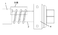
- FIG. 1 is a schematic view (partially sectional view) of a heat exchanger 11 according to Embodiment 1 of the present invention.
- the heat exchanger 11 according to the first embodiment of the present invention is inserted into the inner pipe 1, the outer pipe 3 spirally wound so as to be in close contact with the outer surface of the inner pipe 1, and the inside of the inner pipe 1.
- the insert 2 is composed of an insert shaft 21 and a spiral projection 22.
- the helical winding direction of the outer tube 3 and the helical direction of the helical protrusion 22 are the same direction, and the winding pitch is also the same.
- the heat exchanger 11 is configured to exchange heat between the first fluid, water, and the second fluid, carbon dioxide, via the inner pipe 1 and the outer pipe 3.
- a flow path through which water flows is a spiral flow path formed by the inner surface of the inner pipe 1, the outer surface of the insert shaft portion 21, and the adjacent spiral projection 22, and the inner pipe 1 and an insert 2 inserted into the inner tube 1.
- the inner pipe 1 since it is not necessary to perform bending processing to form the water flow path, the inner pipe 1 does not buckle and flatten, and the thickness of the inner pipe 1 can be designed (thick + rot in consideration of the pressure resistance) The minimum thickness can be based on As a result, it is possible to provide a lightweight heat exchanger which is excellent in economy.
- the vertical axis shows the Nusselt number Nu
- the horizontal axis shows d / D.
- the (d / D) of the heat exchanger similar to patent document 1 mounted in the existing heat pump water heater is 0.2 or less.
- the spiral flow passage 11 of the present invention since the spiral flow passage is constituted by two parts, the curvature diameter D of the spiral flow passage through which water flows can be made significantly smaller than in the prior art. . Therefore, (d / D) is increased, and the stirring effect by the secondary flow is increased. Thereby, while the heat transfer promotion effect improves, a compact heat exchanger can be provided.
- FIGS. 2A and 2B are perspective views showing the flow of fluid flowing through the heat exchanger 11 in the first embodiment of the present invention.
- Water which is the first fluid, flows in a spiral flow path formed by the inner surface of the inner pipe 1, the outer surface of the insert shaft 21 and the adjacent spiral projection 22.
- the pitch is synchronized with the helical protrusion 22 of the insert 2 and the winding direction, and carbon dioxide, which is the second fluid flowing inside the outer tube 3 wound around the opposing portion of the helical channel, and the first Water, which is a fluid, is configured to exchange heat.
- pipe 3 to wind are not wound around the opposing part of a helical flow path, it is just the range which can implement
- a plurality of outer tubes 3 through which the second fluid flows may be provided and alternately wound around the opposing portions of the spiral flow channels.
- FIG. 3 is a cross-sectional view of the heat exchanger 11 in the first embodiment of the present invention. Since the water flow path of the heat exchanger is composed of the two parts of the inner pipe 1 and the insert 2, the longest distance from the water side heat transfer surface is the diameter a of the insert shaft 21 and the spiral projection 22 Can be designed from the projection height th.
- the channel cross-sectional area S can be designed by changing the winding pitch P of the spiral projection 22 of the insert 2 so that the water pressure loss of the water transfer pump for transferring water is acceptable in the device. As a result, the dead water area can be significantly reduced within the water pressure loss restriction range.
- the diameter a of the insert shaft portion 21 and the projection height th of the spiral projection 22 are designed such that the heat exchange performance satisfies a predetermined performance within the range of the following (Expression 4) Is desirable.
- the flow passage cross section of the spiral flow passage which is a water flow passage, is formed into a rectangular cross section by the inner surface of the inner pipe 1, the insert shaft portion 21 and the spiral projection 22. Vortexing is more likely to occur and the secondary flow effect is greater than when the cross section is circular.
- the water flow path is constituted by the two parts of the inner pipe 1 and the insert 2 having the spiral projection 22, so that the spiral flow is performed without winding the inner pipe 1. It forms a road.
- it is possible to provide a lightweight and economical heat exchanger that minimizes the thickness of the inner pipe 1.
- the radius of curvature D of the spiral flow passage can be made significantly smaller than that of the prior art, it is possible to provide a compact heat exchanger having high heat transfer performance.
- the longest distance from the heat transfer surface of the water side flow passage can be designed by the diameter a of the insert shaft 21 and the height th of the projection of the spiral projection 22, and the flow passage cross sectional area S is the water pressure
- the winding pitch P of the helical protrusion 22 can be changed and designed so that the loss is within the constraints. As a result, it is possible to provide a heat exchanger with high heat transfer performance with significantly reduced dead area within the constraints of water pressure loss.
- Second Embodiment 5A and 5B are enlarged views of the spiral protrusion 22 of the insert 2 of the heat exchanger 11 in the second embodiment.
- 6A and 6B are cross-sectional views of the heat exchanger in the same embodiment.
- FIG. 7 is a perspective view of the joint and the insert of the heat exchanger in the same embodiment.
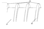
- the axial direction of the heat exchanger 11 that is, the axis of the insert 2 Along the direction, there are provided projections 25 aligned in series.
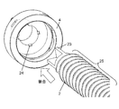
- the axial end of the insert 2 is a protrusion 23, and the joint 4 has a recess 24 that mates with the protrusion 23 of the end of the insert 2. ing.
- the insert 2 is engaged with the projection 23 at the axial end of the insert 2 and the recess 24 of the joint 4 so that the projection 25 on the outer surface of the helical projection 22 contacts the inner pipe 1 It is fixed to
- water which is the first fluid flowing in the spiral flow passage formed between the inner pipe 1 and the insert 2
- the second fluid The heat exchange between the carbon dioxide flowing inside the outer tube 3 and the carbon dioxide flowing through the inner tube 1 and the outer tube 3 is a countercurrent flow via the inner tube 1 and the outer tube 3.
- the temperature of the incoming water flowing into the heat exchanger 11 is high, the heated water may be boiled in the heat exchanger 11. Therefore, the flow rate of the water conveyed to the heat exchanger 11 is increased and the hot water is discharged
- the temperature is adjusted to be less than or equal to a predetermined temperature.
- the hot water temperature can not be kept below the predetermined temperature, which also has a problem of impairing the reliability of the equipment.
- the increase in water pressure loss can be suppressed, and the flow rate that can be conveyed by the pump at the same head increases, so a flow rate sufficient to keep the outlet temperature of outgoing water below a predetermined temperature can be secured. Reliability improves.
- the joint 4 is fitted to the insert 2 and is configured to cover the inner pipe 1 from the outer side and fix it with a fastening body such as the insertion pin 5 (see FIG. 1).
- the position of is fixed.
- the outer surface of the helical protrusion 22 of the insert 2 has the protrusions 25 arranged continuously along the axial direction of the heat exchanger 11, and
- the joint 4 fixes the inner pipe 1 and the insert 2 so that the inner pipe 1 contacts the inner surface of the inner pipe 1.
- the flow path can be formed in the axial direction of the heat exchanger 11, so that even when the water flowing through the heat exchanger 11 has a large flow rate, the heat that suppresses the increase in water pressure loss An exchanger 11 can be provided. Thereby, the energy saving property of the apparatus carrying the heat exchanger 11 of this Embodiment 2 improves.
- FIG. 8 is a cross-sectional view of the heat exchanger in the third embodiment.
- the same parts as those of the first and second embodiments of the present invention will be assigned the same reference numerals and detailed explanations thereof will be omitted.
- the heat exchanger according to the fourth embodiment of the present invention is configured such that the relationship between the tip width t1 of the helical protrusion 22 of the insert 2 and the root width t2 is t1 ⁇ t2.
- the heat exchanger 11 also includes water, which is the first fluid flowing in the spiral flow passage formed between the inner pipe 1 and the insert 2, Carbon dioxide, which is the second fluid flowing inside the outer pipe 3, exchanges heat in the opposite flow via the inner pipe 1 and the outer pipe 3.
- the width L of the heat transfer surface is P ⁇ t1 obtained by subtracting the tip width t1 of the helical protrusion 22 from the helical pitch P of the helical protrusion 22 as shown in FIG.
- the shape of the helical protrusion 22 of the insert 2 is configured to be t1 ⁇ t2.
- the helical protrusion 22 has a constant thickness.
- Heat transfer of water, which is the first fluid flowing in the spiral flow path formed between the inner pipe 1 and the insert 2 to carbon dioxide, which is the second fluid flowing inside the outer pipe 3, than in the case The width L of the face can be increased.
- the heat transfer area of water, which is the first fluid flowing in the spiral flow passage formed between the inner pipe 1 and the insert 2, to carbon dioxide, which is the second fluid flowing inside the outer pipe 3, is In order to expand, it is possible to provide a heat exchanger with higher heat exchange performance.
- FIG. 9 shows that the length of the spiral flow passage formed between the inner pipe 1 and the insertion body 2 and the water side flow passage cross sectional area S are constant, that is, the insert collision in the water side pressure loss equivalent condition It shows the relationship between the portion tip width t1 and the heat exchange capacity Q.
- the heat transfer area of water, which is the first fluid flowing through the spiral flow channel, is expanded. This improves the heat exchange capacity.
- the root shape of the helical protrusion 22 may be R-shaped in order to suppress separation of the secondary flow at the root portion and to reduce water-side pressure loss. Thereby, the friction loss of water due to the vortex can be reduced, so that the energy efficiency of the heat exchanger of the present embodiment and the device equipped with the same can be improved.
- the relationship between the tip width t1 of the helical protrusion 22 of the insertion body 2 and the root width t2 is t1 ⁇ t2.
- FIG. 10 is a block diagram of a refrigeration cycle apparatus according to a fourth embodiment.
- FIG. 10 is a refrigerating-cycle apparatus mounted, for example in a heat pump water heater.
- the refrigeration cycle apparatus includes a compressor 101, a radiator 102 which is the heat exchanger 11 according to the first to third embodiments of the present invention, a pressure reducing device 103 which is an electronic expansion valve, and an evaporator 104. To make up the refrigerant circuit 105.
- the refrigerant circuit includes an evaporator outlet temperature detection unit 107 that detects the temperature of the refrigerant flowing out of the evaporator 104, and the refrigeration cycle apparatus includes a controller 110 and a defrosting operation mode.
- the refrigerant circuit 105 carbon dioxide is sealed as a refrigerant, and the high pressure side is operated in a supercritical state during operation of the compressor 101.
- the insert 2 having the spiral protrusion 22 constituting the radiator 102 (the heat exchanger 11 according to the first embodiment or the second embodiment of the present invention) is made of resin having a volume specific heat larger than that of metal. (Copper: 0.04 J / m 3 ⁇ K, PPS: 0.65 J / m 3 ⁇ K).
- the compressor 101 When the compressor 101 is operated, the refrigerant compressed and discharged to a high pressure is sent to the radiator 102 and exchanges heat with the low temperature water supplied through the water inlet pipe 111 by the water transfer pump 113 to dissipate heat.
- the low temperature water heated by this becomes high temperature water passes through the hot water discharge pipe 112, is sent to a hot water storage tank (not shown), and is stored as high temperature hot water.
- the refrigerant flowing out of the radiator 102 is supplied to the pressure reducing device 103, decompressed and expanded, sent to the evaporator 104, heat-exchanged with the air introduced by the blower 106, and evaporated to gasify.
- the gasified refrigerant is drawn into the compressor 101.
- the evaporator 104 When the hot water storage operation is performed in a state where the outside air temperature is low, the evaporator 104 is frosted, and the heat exchange capacity of the evaporator 104 is significantly reduced.
- the control device 110 performs a defrosting operation for defrosting the frost adhering to the evaporator 104 and recovering the heat exchange capacity of the evaporator 104.
- the defrosting operation is performed when frost adheres to the evaporator 104 and the temperature detected by the evaporator outlet temperature detection means 107 falls below a predetermined temperature. The defrosting operation will be specifically described below.
- the control device 110 stops the water transfer pump 113 for supplying water to the radiator 102 and the blower 106 to reduce the flow path resistance of the pressure reducing device 103.
- the high-temperature refrigerant compressed by the compressor 101 passes through the radiator 102 and the pressure reducing device 103, flows into the evaporator 104, is defrosted by the heat of the refrigerant, and is drawn into the compressor 101.
- the defrosting operation ends and the boiling operation is performed.
- the heat quantity stored in the radiator 102 is also utilized to defrost the evaporator 104.
- a radiator by making the insert 2 which is a part of the flow path of the radiator 102 a resin (copper: 0.04 J / m 3 ⁇ K, PPS: 0.6 5 J / m 3 ⁇ K) having a larger specific heat than metal
- the heat storage amount of 102 increases, and more heat can be used from the radiator 102 at the time of defrosting. Thereby, the defrosting operation can be completed in a short time, and the defrosting performance of the device is improved.
- the insert 2 having the spiral projection 22 is made of resin (PPS)
- PPS resin
- similar effects can be obtained if it is a resin other than PPS or a material having a large volume specific heat. Can be expected.
- the refrigerant flowing through the outer pipe 3 is carbon dioxide, but it is also possible to use a hydrocarbon-based or HFC-based refrigerant (such as R410A) or an alternative refrigerant thereof. Expected effects.
- the heat exchanger according to the present invention can provide a heat exchanger that is compact and economical and has high quality performance and heat exchange performance. Therefore, the present invention can be applied to an apparatus equipped with a heat exchanger that performs heat exchange between fluids.
Landscapes
- Engineering & Computer Science (AREA)
- Physics & Mathematics (AREA)
- Thermal Sciences (AREA)
- Mechanical Engineering (AREA)
- General Engineering & Computer Science (AREA)
- Chemical & Material Sciences (AREA)
- Combustion & Propulsion (AREA)
- Heat-Exchange Devices With Radiators And Conduit Assemblies (AREA)
- Heat-Pump Type And Storage Water Heaters (AREA)
Abstract
本発明に係る熱交換器は、第1流体が流れる内管と、内管に挿入される挿入体とを備えている。さらに、熱交換器は、内管の外周に設けられ、第2流体が流れる外管を備えている。挿入体は、軸部と軸部の外表面に形成された螺旋状突部とを備えている。第1流体は、内管の内面と軸部と螺旋状突部とで形成される螺旋状流路を流れる。この構成により、コンパクトで経済性に優れ、品質性能および熱交換性能の高い熱交換器を提供することができる。
Description
本発明は、流体間で熱交換を行う熱交換器に関する。
従来、この種の熱交換器として、水管と冷媒管を二重螺旋状に巻き付けた熱交換器が提案されている(例えば、特許文献1参照)。また、水管に冷媒管を巻付けた熱交換器が提案されている(例えば、特許文献2)。
この種の熱交換器を搭載しているヒートポンプ給湯機は、主として夜間に一定の時間をかけて湯を沸かす装置であり、沸き上げ運転時に、同給湯機が備える熱交換器を流れる水の流速は比較的小さい。
したがって、熱交換器を流れる水の流れは層流であることから、熱交換器としての伝熱性能を向上させるためには、水の流れを乱れさせ、水側の伝熱性能を向上させることが必須である。
図11は、特許文献1に記載された従来の熱交換器の概要図(一部断面図)である。図12は、図11の熱交器の断面を示す拡大図である。
熱交換器201は、水管202と、1本の水管202に対して1本以上の冷媒管203とを備えている。水管202は、螺旋巻きされることにより略円筒形状に形成されている。冷媒管203は、略円筒形状に形成された水管202の外周に所定のピッチで螺旋巻きされている。さらに、冷媒管203は少なくとも一箇所以上が水管202の略全長にわたり接合されている。水管202を流れる水の流れ方向と、冷媒管203の内部を流れる冷媒の流れ方向とは反対方向である。
上記のように水管202が螺旋状に巻き回されることにより、水管を流れる水に遠心力が働き、管軸に垂直な断面内に、図12に記載の矢印のような二次流れが生じる。ここで、螺旋状流路を流れる水に働く遠心力の大きさは力のつり合いから、

と表される。なお、式(1)において、Fは遠心力、M(M=V×ρ)は質量、Vは体積、ρは密度、vは回転速度、rは回転半径を示している。
式(1)からもわかるように、温度が低く密度の大きい流体ほどより大きな遠心力が働き、螺旋状流路の外側に向かう。このため、伝熱面での水と冷媒との温度差が拡大し、伝熱が促進される。
したがって、水の流れが層流であっても二次流れにより、主流に垂直な断面内の温度場が改善されるので、水管と冷媒管を接合した直管状の熱交換器に比べて大幅に伝熱性能を向上させることができる。
図13は、特許文献2に記載された従来の熱交換器の概略図である。
熱交換器301は、直線部を有する水管302と、1本の水管302に対して1本以上の冷媒管303とを備えている。冷媒管303は水管302に巻き付けられており、水管302の内部には伝熱促進手段としてねじりテープが挿入されている。
このように、水管にねじりテープを挿入し、旋回流を発生させることで、水側の流れを乱し、伝熱性能を向上させている。
しかしながら、上記特許文献1における構成では、管を螺旋状に巻き回して熱交換器が形成されるため、管の材質、及び、管径や肉厚によっては、水管が扁平したり、また、座屈したりする可能性がある。
そのため、扁平による減肉を考慮して水管の肉厚を厚くして、座屈が起こらないように螺旋管の曲率直径Dを大きくとる必要がある。これは、コストアップにつながるとともに、熱交換器の容積が大きくなってしまう。さらに、遠心力による二次流れでの伝熱促進効果が小さくなってしまうという課題を有していた。
また、管の巻きピッチを広くとれば、座屈のリスクは減少するが、デッドスペースが多い冗長な熱交換器となってしまい、熱交換器の容積が不必要に大きくなるという課題も有していた。
また、上記特許文献2における構成では、ねじりテープにより発生した旋回流で伝熱面近傍の温度分布は改善されるが、伝熱面からの距離が最も離れている水管の中心軸上の温度分布の改善効果は伝熱面近傍に比べて小さい。
すなわち、水管の中心軸上には伝熱の寄与が小さい死水域ができてしまう。また、死水域を減らすために水管の管径を小さくすると、水圧損が過大になってしまい、水搬送ポンプの動力が大きくなる。これにより、熱交換器を搭載した機器のランニングコストが増加してしまうという課題を有していた。
本発明は、上記従来の課題を解決するもので、コンパクトで経済性に優れ、品質性能および熱交換性能の高い熱交換器を提供することを目的とする。
上記目的を達成するために、本発明の熱交換器は、第1流体が流れる内管と、内管に挿入される挿入体と、内管の外周に設けられ、第2流体が流れる外管とを備えている。挿入体は、軸部と軸部の外表面に形成された螺旋状突部とを備えている。第1流体は、内管の内面と軸部と螺旋状突部とで形成される螺旋状流路を流れる。
これにより、第1流体が流れる螺旋状流路は、内管と螺旋状突部を有する挿入体との二部品で形成できるので、流路の形成に内管を巻き回す必要がない。そのため、内管が座屈や扁平することがないので、管の肉厚を必要最小限にすることができ、経済性に優れた軽量な熱交換器を提供できる。
また、螺旋状流路の曲率直径を従来よりも小さく設定できるので、二次流れによる伝熱促進効果が大きく、かつ、コンパクトな熱交換器を提供できる。
加えて、第1流体の伝熱面からの最長距離は、挿入体の軸径と螺旋状突部の突部高さで決定される。これにより、流路断面積は水搬送ポンプが許容できる水圧損となるように、螺旋状突部のピッチを変更できる。したがって、水圧損制約範囲内で死水域を大幅に低減した熱交換性能の高い熱交換器を提供できる。
本発明によれば、コンパクトで経済性に優れ、品質性能および熱交換性能の高い熱交換器を提供できる。
第1の発明に係る熱交換器は、第1流体が流れる内管と、内管に挿入される挿入体と、内管の外周に設けられ、第2流体が流れる外管とを備えている。挿入体は、軸部と軸部の外表面に形成された螺旋状突部とを備えている。第1流体は、内管の内面と軸部と螺旋状突部とで形成される螺旋状流路を流れる。
これにより、第1流体が流れる螺旋状流路は、内管と螺旋状突部を有する挿入体との二部品で形成できるので、内管が座屈や扁平することがなく、管の肉厚を必要最小限とした経済性に優れ、かつ、軽量な熱交換器が提供できる。
また、螺旋状流路の曲率直径を従来よりも小さくとれるので、二次流れによる伝熱促進効果が大きく、かつ、コンパクトな熱交換器が提供できる。
加えて、第1流体の伝熱面からの最長距離は、挿入体の軸径と螺旋状突部高さに設定され、流路断面積は、搬送ポンプが許容できる圧力損失となるようにできるので、圧力損失制約範囲内で死水域を大幅に低減した従来よりも熱交換性能の高い熱交換器を提供できる。
第2の発明は、特に第1の発明において、外管の巻付け方向と螺旋状突部の螺旋方向とは同じ方向であり、かつ、第1流体と第2流体との流れが対向流となるように構成されている。
これにより、第1流体と第2流体とが対向流で熱交換できるので、熱交換性能の高い熱交換器を提供できる。
第3の発明は、特に第1または第2の発明において、内管の外周で螺旋状流路の対向部に、外管が配置されている。
これにより、熱交換器略全域において、第1流体と第2流体とが熱交換できるので、より熱交換性能の高い熱交換器を提供できる。
第4の発明は、特に第1~第3のいずれかの発明において、内管、挿入体をそれぞれ固定する継手を備えている。
これにより、如何なる設置状態(縦置き、横置き、斜め置き)においても、内管内における螺旋状突部を有する挿入体の配置位置が固定されるので、設置自由度の向上した熱交換器を提供できる。
第5の発明は、特に第1~第4のいずれかの発明において、螺旋状突部は、内管と接する複数の突起を備えている。複数の突起は、軸方向に沿って連続して並ぶ。
これにより、突起部を除いた螺旋状突部と内管との間には隙間が生じ、螺旋状流路に加えて熱交換器軸方向に沿って連通した流路を形成できる。その結果、二次流れにより流れを攪拌しつつ、第1流体に作用する遠心力が大きな大流量時には、当該隙間を流れる第1流体のバイパス量が増加する。
したがって、大流量時にも熱交換器での圧力損失の増加を抑制でき、第1流体を搬送する搬送ポンプが要する動力が少なくなるため、機器の省エネルギー性が向上する。
また、第1流体の流入温度が高い場合には、第1流体の流出温度が異常に高くならないように、第1流体の流量を増加させる必要がある。本発明によれば同揚程のポンプで搬送できる流量が増加するため、第1流体の流出温度を所定の温度以下にするのに十分な流量を確保することができ、機器の信頼性が向上する。
第6の発明は、特に第1~第5のいずれかの発明において、螺旋状突部の先端幅をt1、根元幅をt2としたとき、t1<t2の関係である。
これにより、外管の内部を流れる第2流体への、内管と挿入体との間に形成された螺旋状流路を流れる第1流体の伝熱面積が拡大できるため、熱交換性能が高い熱交換器を提供することができる。
第7の発明は、少なくとも圧縮機、第1~第6のいずれかの発明の熱交換器、減圧装置、および蒸発器を環状に接続した冷媒回路と、制御装置とを備え、蒸発器の着霜を溶かす除霜運転モードを備え、挿入体は樹脂製である冷凍サイクル装置である。
第1流体の流路の一部を金属よりも比熱の大きな樹脂で形成(銅:0.04J/m3・K、PPS:0.65J/m3・K)することにより、熱交換器の蓄熱量が増加し、除霜時により多くの熱量を熱交換器から利用できる。したがって、短時間で除霜運転を終えることができ、機器の除霜性能が向上する。
以下、本発明の実施の形態について、図面を参照しながら説明する。なお、この実施の形態によって本発明が限定されるものではない。
(実施の形態1)
図1は、本発明の実施の形態1における熱交換器11の概略図(一部断面図)である。
図1は、本発明の実施の形態1における熱交換器11の概略図(一部断面図)である。
本発明の実施の形態1における熱交換器11は、内管1と、内管1の外表面に密着するように螺旋状に巻き付けられた外管3と、内管1の内部に挿入される挿入体2とから構成されている。挿入体2は、挿入体軸部21と螺旋状突部22とから構成されている。
そして、外管3の螺旋状の巻付け方向と螺旋状突部22の螺旋方向とは同じ方向であり、また、巻付けピッチも同じとなるように構成されている。
以上のように構成された熱交換器について、以下にその動作を説明する。
熱交換器11は、第1流体である水と第2流体である二酸化炭素とが、内管1及び外管3を介して熱交換する構成である。
熱交換器11において、水が流れる流路は、内管1の内面と、挿入体軸部21の外面と、隣接する螺旋状突部22とで形成される螺旋状流路であり、内管1と、内管1に挿入される挿入体2との二部品によって形成される。
したがって、その水流路を形成するために曲げ加工を行う必要がないため、内管1が座屈、扁平することがなく、内管1の肉厚を設計思想(耐圧を考慮した肉厚+腐れ代)に基づいた最少肉厚とすることができる。これにより、経済性に優れた軽量な熱交換器を提供できる。
次に、螺旋状流路の曲率直径Dと管内の熱伝達率について説明する。
螺旋管のような曲がった円管内の発達した領域における熱伝達率については、日本機械学会 伝熱工学資料 改定第5版に、以下のように示されている。


ここで、Nuはヌセルト数、Prはプラントル数、Reはレイノルズ数を示している。そして、Dは螺旋状流路中心軸の曲率直径で、dは管の相当直径である。図4は、レイノルズ数Re=2000、水温40℃の条件において、(d/D)を変化させたときのヌセルト数Nuを上記数式(3)を用いて試算したものである。縦軸はヌセルト数Nuを示し、横軸はd/Dを示す。
上記数式(2)、数式(3)、及び図4からもわかるように、同レイノルズ数、同プラントル数下では、管の相当直径dが大きいほど、または、曲率直径Dが小さいほど円管内のヌセルト数は大きくなる。
すなわち、管内の熱伝達率は高くなるので、熱交換器の伝熱性能が向上する。既存のヒートポンプ給湯機に搭載されている特許文献1に類する熱交換器の(d/D)は0.2以下である。これに対し、本発明の熱交換器11は、螺旋状流路が二部品で構成されているため、水の流れる螺旋状流路の曲率直径Dを、従来よりも大幅に小さくすることができる。したがって、(d/D)が大きくなり、二次流れによる攪拌効果が増加する。これにより、伝熱促進効果が向上するとともに、コンパクトな熱交換器を提供できる。
図2AおよびBは、本発明の実施の形態1における熱交換器11を流れる流体の流れを示す斜視図である。
第1流体である水は、内管1の内面と、挿入体軸部21の外面と、隣接する螺旋状突部22とで形成された螺旋状流路を流れる。挿入体2の螺旋状突部22と巻付け方向とはピッチが同期しており、螺旋状流路の対向部に巻き付けられた外管3の内部を流れる第2流体である二酸化炭素と第1流体である水とは熱交換をする構成である。
ここで、内管1と挿入体2との間の螺旋状流路を流れる水と、外管3の内部を流れる二酸化炭素は流れる方向が反対であるため、図2AおよびBに示した流れのように、熱交換器11の略全域にわたって対向流で熱交換でき、高効率な熱交換器が提供できる。
なお、巻き付ける外管3のすべての部位が、螺旋状流路の対向部に巻き付けられていなくとも、搭載する機器が必要する熱交換効率を実現できる範囲であれば良い。また、第2流体が流れる外管3を複数本備え、交互に螺旋状流路の対向部に巻き付けていても良い。
図3は、本発明の実施の形態1における熱交換器11の断面図である。熱交換器の水流路は、内管1と挿入体2との二部品で構成されるので、水側伝熱面からの最長距離は、挿入体軸部21の直径aと螺旋状突部22の突部高さthとから設計できる。
また、流路断面積Sは、機器において、水を搬送する水搬送ポンプが許容できる水圧損となるように、挿入体2の螺旋状突部22の巻きピッチPを変更して設計できる。これにより、水圧損制約範囲内で、死水域を大幅に低減することができる。ここで、挿入体軸部21の直径aと螺旋状突部22の突部高さthは、下記の(式4)の範囲内で、熱交換性能が所定の性能を満たすように設計されることが望ましい。

また、本発明の実施の形態1においては、水流路である螺旋状流路の流路断面を、内管1の内面と挿入体軸部21と螺旋状突部22とで矩形断面に形成しており、断面が円形の場合に比べて渦が発生しやすく二次流れの効果が大きくなる。
以上のように、本実施の形態1においては、水流路を内管1と螺旋状突部22を有する挿入体2との二部品で構成したことにより、内管1を巻き回すことなく螺旋流路を形成している。これにより、内管1の肉厚を必要最小限とした軽量で経済性に優れた熱交換器が提供できる。
また、従来よりも螺旋状流路の曲率直径Dを大幅に小さくできるので、コンパクトで伝熱性能が高い熱交換器を提供できる。
加えて、水側流路の伝熱面からの最長距離は、挿入体軸部21の直径aと螺旋状突部22の突部の高さthで設計でき、流路断面積Sは、水圧損が制約内となるよう、螺旋状突部22の巻きピッチPを変更して設計できる。これにより、水圧損の制約範囲内で、死水域を大幅に低減した伝熱性能の高い熱交換器を提供できる。
(実施の形態2)
図5AおよびBは、本実施の形態2における熱交換器11の挿入体2の螺旋状突部22の拡大図である。図6AおよびBは、同実施の形態における熱交換器の断面図である。図7は、同実施の形態における熱交換器の継手と挿入体の斜視図である。
図5AおよびBは、本実施の形態2における熱交換器11の挿入体2の螺旋状突部22の拡大図である。図6AおよびBは、同実施の形態における熱交換器の断面図である。図7は、同実施の形態における熱交換器の継手と挿入体の斜視図である。
尚、本発明の実施の形態1と同一部品については、同一符号を付して、詳細な説明を省略する。
図5Bに示すように、本実施の形態2の熱交換器11を構成する挿入体2の螺旋状突部22の外表面には、熱交換器11の軸方向、すなわち、挿入体2の軸方向に沿って、連続して並んだ突起25が設けられている。また、図7に示すように、挿入体2の軸方向の端部は凸部23となっており、継手4は、挿入体2の端部の凸部23と篏合する凹部24を有している。
挿入体2は、挿入体2の軸方向の端部の凸部23と、継手4の凹部24を篏合して、螺旋状突部22の外表面の突起25が、内管1と接するように固定されている。
尚、挿入体2と継手4の篏合部の形状について、本実施の形態2では凸部と凹部としたが、篏合できるほかの如何なる形状であっても構わない。
以上のように構成された熱交換器について、以下その動作を説明する。
本実施の形態においては、突起25を除いた螺旋状突部22と内管1との間に隙間が生じているので、実施の形態1に記載の螺旋状流路に加えて、熱交換器11の軸方向、すなわち、挿入体2の軸方向に沿って連通した流路(バイパス流路50)が形成されている。
本実施の形態2の熱交換器11も、実施の形態1と同様に内管1と挿入体2との間に形成された螺旋状流路を流れる第1流体である水と、第2流体である外管3の内部を流れる二酸化炭素とが、内管1及び外管3を介して対向流で熱交換する構成である。
ここで、熱交換器11に流入する入水温度が高い場合は、加熱された水が熱交換器11内で沸騰する恐れがあるため、熱交換器11に搬送される水の流量を増やして出湯温度が所定の温度以下となるように調整される。
しかしながら、上記特許文献1に記載の従来の熱交換器では、管を巻き回して螺旋状流路を形成しているため、直線上流路に比べて流路長が長くなる。したがって、大流量時には熱交換器での水圧損が大きくなるので、水を搬送する機器のポンプ動力が過大となり機器の省エネルギー性を損ねるという課題があった。
また、熱交換器11での水圧損が、ポンプの搬送能力を超える場合には、出湯温度を所定の温度以下に留めることができず、機器の信頼性を損ねてしまうという課題も有していた。
一方、本実施の形態2の熱交換器11は、螺旋状流路に加えて、図6に示すように、内管1と突起25を除いた、内管1の内面と螺旋状突部22との間に、熱交換器11の軸方向、すなわち、挿入体2の軸方向に沿って連通したバイパス流路50を持つ。
このため、二次流れにより流れを攪拌しつつ、水に作用する遠心力が大きな大流量時には、熱交換器11の軸方向、すなわち、挿入体2の軸方向に連通した流路を流れる水のバイパス量が増加する。
したがって、大流量時の圧力損失の増加を、上記特許文献1に記載の従来の熱交換器に比べて抑制でき、搬送ポンプの要する動力が少なくなるため、機器の省エネルギー性が向上する。
また、水圧損の増加を抑制でき、同揚程のポンプで搬送できる流量が増加するので、流出する水の出湯温度を所定の温度以下に留めるのに十分な流量を確保することができ、機器の信頼性が向上する。
さらに、継手4は、挿入体2と篏合し、内管1を外方から覆い挿入ピン5等の締結体にて固定する構成(図1参照)としており、挿入体2と内管1との位置が固定されている。これにより、如何なる設置状態(縦置き、横置き、斜め置き)においても、螺旋状突部22と内管1との間に熱交換器11の軸方向、すなわち、挿入体2の軸方向に沿って連通した流路を確保できる。
したがって、圧力損失の増加を抑制しつつ、設置自由度の向上した熱交換器を提供できる。
以上のように、本実施の形態2においては、挿入体2の螺旋状突部22の外表面に熱交換器11の軸方向に沿って連続して並んだ突起25を有し、突起25と内管1の内面とが接するように継手4で、内管1、挿入体2を固定している。これにより、螺旋状流路に加えて、熱交換器11の軸方向にも流路を形成できるので、熱交換器11を流れる水が大流量の場合においても、水圧損の増加を抑制した熱交換器11が提供できる。これにより、本実施の形態2の熱交換器11を搭載した機器の省エネルギー性が向上する。
なお、突起25がない場合においても、継手4は、挿入体2と篏合し、内管1を外方から覆い締結体にて固定する構成(図5A参照)とすることにより、如何なる設置状態(縦置き、横置き、斜め置き)においても、螺旋状突部22と内管1との間に熱交換器11の軸方向、すなわち、挿入体2の軸方向に沿って連通した流路(バイパス流路50)を確保できる。これにより、螺旋状突部22と内管1との間を適正な距離で設定することで、水圧損の増加を抑制しつつ、設置自由度の向上した熱交換器11を提供できる。
(実施の形態3)
図8は、本実施の形態3における熱交換器の断面図である。尚、本発明の実施の形態1、2と同一部品については、同一符号を付して、詳細な説明を省略する。
図8は、本実施の形態3における熱交換器の断面図である。尚、本発明の実施の形態1、2と同一部品については、同一符号を付して、詳細な説明を省略する。
本発明の実施の形態4における熱交換器は、挿入体2の螺旋状突部22の先端幅t1と、根元幅t2の関係がt1<t2となるように構成されている。
以上のように構成された熱交換器について、以下にその動作を記載する。
本実施の形態4の熱交換器11も、実施の形態1、2と同様に、内管1と挿入体2との間に形成された螺旋状流路を流れる第1流体である水と、外管3の内部を流れる第2流体である二酸化炭素が、内管1及び外管3を介して対向流で熱交換する構成である。
熱交換器11の、外管3の内部を流れる第2流体である二酸化炭素への、内管1と挿入体2との間に形成された螺旋状流路を流れる第1流体である水の伝熱面の幅Lは、図8に示すように、螺旋状突部22の螺旋ピッチPから螺旋状突部22の先端幅t1を差し引いたP-t1である。
本実施の形態においては、図8に示すように、挿入体2の螺旋状突部22の形状がt1<t2となるように構成されている。これにより、実施の形態1の図3に示すような、螺旋状突部22の厚みが一定の場合と同様の水側流路断面積Sを維持しつつ、螺旋状突部22が厚み一定の場合よりも、外管3の内部を流れる第2流体である二酸化炭素への、内管1と挿入体2との間に形成された螺旋状流路を流れる第1流体である水の伝熱面の幅Lを、拡大することができる。
すなわち、外管3の内部を流れる第2流体である二酸化炭素への、内管1と挿入体2との間に形成された螺旋状流路を流れる第1流体である水の伝熱面積が拡大するため、より熱交換性能が高い熱交換器を提供できる。
図9は、内管1と挿入体2との間に形成された螺旋状流路の長さ及び水側流路断面積Sを一定、すなわち、水側圧力損失同等条件での、挿入体突部先端幅t1と熱交換能力Qの関係を示したものである。
図9からわかるように、螺旋状突部22の先端幅t1が小さいほど、外管3の内部を流れる第2流体である二酸化炭素への、内管1と挿入体2との間に形成された螺旋状流路を流れる第1流体である水の伝熱面積が拡大する。これにより、熱交換能力が向上する。
また、螺旋状突部22の根元形状は、根元部での二次流れの剥離を抑制し、水側圧力損失を低減するためにR形状であってもよい。これにより、渦による水の摩擦損失を低減できるので、本実施の形態の熱交換器やそれを搭載した機器のエネルギー効率を向上することができる。
以上のように、本実施の形態3においては、挿入体2の螺旋状突部22の先端幅t1と、根元幅t2の関係がt1<t2となるように構成されている。これにより、水側流路条件(内管1と挿入体2との間に形成された螺旋状流路の長さ及び水側流路断面積S)を変更することなく、すなわち、水側圧力損失同等条件下でありながら、外管3の内部を流れる第2流体である二酸化炭素への、内管1と挿入体2との間に形成された螺旋状流路を流れる第1流体である水の伝熱面の長さを長くできる。その結果、伝熱面積を拡大することができるため、熱交換性能の高い熱交換器が提供できる。
(実施の形態4)
図10は、本実施の形態4における冷凍サイクル装置の構成図である。
図10は、本実施の形態4における冷凍サイクル装置の構成図である。
尚、本発明の実施の形態1~3と同一構成については、同一符号を付して詳細な説明を省略する。
図10は、例えば、ヒートポンプ給湯機に搭載される冷凍サイクル装置である。冷凍サイクル装置は、圧縮機101、本発明の実施の形態1から3に記載の熱交換器11である放熱器102、電子膨張弁である減圧装置103、および蒸発器104を備え、それらを環状に接続して冷媒回路105を構成している。
冷媒回路は、蒸発器104から流出した冷媒の温度を検知する蒸発器出口温度検知手段107を備え、冷凍サイクル装置は、制御装置110と、除霜運転モードを備えている。
冷媒回路105内には、冷媒として二酸化炭素が封入されており、圧縮機101の運転時は、高圧側が超臨界状態で運転される。
また、放熱器102(本発明の実施の形態1または実施の形態2に記載の熱交換器11)を構成する螺旋状突部22を有する挿入体2は、金属よりも容積比熱の大きい樹脂製(銅:0.04J/m3・K、PPS:0.65J/m3・K)である。
以上のように構成された冷凍サイクル装置について、以下にその動作および作用を説明する。
圧縮機101を運転すると、高圧に圧縮され吐出された冷媒は、放熱器102に送られ、水搬送ポンプ113によって入水配管111を通って送水された低温水と熱交換して放熱する。これにより加熱された低温水は高温水となり、出湯配管112を通り、貯湯タンク(図示せず)に送られ高温の温水として貯湯される。
放熱器102から流出される冷媒は、減圧装置103に供給されて減圧膨張され、蒸発器104に送られて、送風機106により導入された空気と熱交換し、蒸発してガス化する。ガス化した冷媒は、圧縮機101に吸入される。
次に、ヒートポンプ給湯機の除霜運転動作について説明する。
外気温度が低い状態で貯湯運転動作を行うと、蒸発器104に霜が付き、蒸発器104の熱交換能力が大幅に低下してしまう。
そこで、制御装置110は、蒸発器104に付着した霜を除霜し、蒸発器104の熱交換能力を回復させる除霜運転動作を行う。除霜運転動作は、蒸発器104に霜が付着し、蒸発器出口温度検知手段107で検知した温度が、所定の温度を下回ると実行される。以下、除霜運転動作を具体的に説明する。
まず、制御装置110は、放熱器102に水を送水する水搬送ポンプ113と送風機106を停止させ、減圧装置103の流路抵抗を小さくする。圧縮機101で圧縮された高温の冷媒は、放熱器102および減圧装置103を通り、蒸発器104に流入し、冷媒の持つ熱で除霜を行い、圧縮機101に吸入される。
そして、蒸発器出口温度検知手段107で検知された温度が、所定の温度を上回ると、除霜運転動作は終了し、沸き上げ運転が行われる。
この除霜運転時には、圧縮機101から吐出された冷媒の熱量に加え、放熱器102に蓄熱された熱量も活用されて蒸発器104を除霜する。
放熱器102の流路の一部である挿入体2を金属よりも比熱の大きな樹脂(銅:0.04J/m3・K、PPS:0.65J/m3・K)とすることにより、放熱器102の蓄熱量が増加し、除霜時により多くの熱量を、放熱器102から利用できる。これにより、短時間で除霜運転を終えることができ、機器の除霜性能が向上する。
尚、本発明の実施の形態4では、螺旋状突部22を有する挿入体2を樹脂製(PPS)としたが、PPS以外の樹脂、または、容積比熱の大きな材料であれば同様の作用効果を期待できる。
また、本発明の実施の形態1~3では、外管3を流れる冷媒を二酸化炭素としたが、ハイドロカーボン系やHFC系(R410A等)の冷媒、あるいはこれらの代替冷媒とすることも同様の作用効果が期待できる。
なお、以上のそれぞれの実施形態だけでなく、以上のあらゆる実施形態の組み合わせも本発明の範囲内である。
以上のように、本発明にかかる熱交換器は、コンパクトで経済性に優れ、品質性能および熱交換性能の高い熱交換器を提供できる。したがって、本発明は流体間で熱交換を行う熱交換器を搭載した機器に適用できる。
1 内管
2 挿入体
3 外管
4 継手
5 トメワ(挿入ピン)
11 熱交換器
21 挿入体軸部
22 螺旋状突部
23 凸部
24 凹部
25 突起
50 バイパス流路
101 圧縮機
102 放熱器
103 減圧装置
104 蒸発器
105 冷媒回路
2 挿入体
3 外管
4 継手
5 トメワ(挿入ピン)
11 熱交換器
21 挿入体軸部
22 螺旋状突部
23 凸部
24 凹部
25 突起
50 バイパス流路
101 圧縮機
102 放熱器
103 減圧装置
104 蒸発器
105 冷媒回路
Claims (7)
- 第1流体が流れる内管と、
前記内管に挿入される挿入体と、
前記内管の外周に設けられ、第2流体が流れる外管と、
を備え、
前記挿入体は、軸部と前記軸部の外表面に形成された螺旋状突部とを備え、
前記第1流体は、前記内管の内面と前記軸部と前記螺旋状突部とで形成される螺旋状流路を流れることを特徴とする熱交換器。 - 前記外管の巻付け方向と前記螺旋状突部の螺旋方向とは同じ方向であり、
かつ、前記第1流体と前記第2流体との流れが対向流となるように構成されていることを特徴とする請求項1に記載の熱交換器。 - 前記内管の外周で前記螺旋状流路の対向部に、
前記外管が配置されていることを特徴とする請求項1または2に記載の熱交換器。 - 前記内管、前記挿入体をそれぞれ固定する継手を備えたことを特徴とする前記請求項1~3のいずれか1項に記載の熱交換器。
- 前記螺旋状突部は、前記内管と接する複数の突起を備え、
前記複数の突起は、軸方向に沿って連続して並ぶことを特徴とする請求項1~4のいずれか1項に記載の熱交換器。 - 前記螺旋状突部の先端幅をt1、根元幅をt2としたとき、t1<t2の関係であることを特徴とする請求項1~5のいずれか1項に記載の熱交換器。
- 少なくとも圧縮機、前記請求項1~6のいずれか1項に記載の熱交換器、減圧装置、および蒸発器を環状に接続した冷媒回路と、
制御装置と、
を備え、
前記蒸発器の着霜を溶かす除霜運転モードを備え、
前記挿入体は樹脂製であることを特徴とする冷凍サイクル装置。
Priority Applications (3)
| Application Number | Priority Date | Filing Date | Title |
|---|---|---|---|
| CN201680023056.6A CN107532870B (zh) | 2015-04-28 | 2016-04-05 | 热交换器和使用其的制冷循环装置 |
| JP2017515372A JP6687022B2 (ja) | 2015-04-28 | 2016-04-05 | 冷凍サイクル装置 |
| EP16786106.1A EP3290854B1 (en) | 2015-04-28 | 2016-04-05 | Heat exchanger and refrigeration cycle device using same |
Applications Claiming Priority (2)
| Application Number | Priority Date | Filing Date | Title |
|---|---|---|---|
| JP2015-091026 | 2015-04-28 | ||
| JP2015091026 | 2015-04-28 |
Publications (1)
| Publication Number | Publication Date |
|---|---|
| WO2016174826A1 true WO2016174826A1 (ja) | 2016-11-03 |
Family
ID=57199099
Family Applications (1)
| Application Number | Title | Priority Date | Filing Date |
|---|---|---|---|
| PCT/JP2016/001909 WO2016174826A1 (ja) | 2015-04-28 | 2016-04-05 | 熱交換器およびそれを用いた冷凍サイクル装置 |
Country Status (4)
| Country | Link |
|---|---|
| EP (1) | EP3290854B1 (ja) |
| JP (1) | JP6687022B2 (ja) |
| CN (1) | CN107532870B (ja) |
| WO (1) | WO2016174826A1 (ja) |
Cited By (6)
| Publication number | Priority date | Publication date | Assignee | Title |
|---|---|---|---|---|
| WO2018189860A1 (ja) * | 2017-04-13 | 2018-10-18 | 三菱電機株式会社 | 水冷媒熱交換器及び水熱交換器を備えたヒートポンプ装置 |
| WO2019087311A1 (ja) * | 2017-10-31 | 2019-05-09 | 学校法人上智学院 | 放熱装置 |
| WO2019130386A1 (ja) * | 2017-12-25 | 2019-07-04 | 三菱電機株式会社 | 熱交換器の製造方法及び熱交換器 |
| JP2020091072A (ja) * | 2018-12-06 | 2020-06-11 | パナソニックIpマネジメント株式会社 | 熱交換器及びそれを備えた給湯機 |
| EP3760948A4 (en) * | 2018-02-27 | 2021-03-10 | Mitsubishi Electric Corporation | HEAT PUMP UNIT |
| JP2021081154A (ja) * | 2019-11-22 | 2021-05-27 | パナソニックIpマネジメント株式会社 | 熱交換器およびそれを備えた温水生成装置 |
Families Citing this family (1)
| Publication number | Priority date | Publication date | Assignee | Title |
|---|---|---|---|---|
| JP7129602B2 (ja) * | 2019-05-31 | 2022-09-02 | パナソニックIpマネジメント株式会社 | 熱交換器及びそれを備えた冷凍サイクル装置 |
Citations (11)
| Publication number | Priority date | Publication date | Assignee | Title |
|---|---|---|---|---|
| JP2000297991A (ja) * | 1999-03-03 | 2000-10-24 | Hde Metallwerk Gmbh | 熱交換器管 |
| JP2002162175A (ja) * | 2000-11-22 | 2002-06-07 | Sunpot Co Ltd | 二重管式熱交換器 |
| JP2003329376A (ja) * | 2002-05-13 | 2003-11-19 | Atago Seisakusho:Kk | 2重管式熱交換器 |
| WO2006103788A1 (ja) * | 2005-03-25 | 2006-10-05 | Tsinghua University | 給湯用伝熱管 |
| JP2008190777A (ja) * | 2007-02-05 | 2008-08-21 | Corona Corp | 水冷媒熱交換器 |
| JP2008292107A (ja) * | 2007-05-28 | 2008-12-04 | Furukawa Electric Co Ltd:The | 熱交換器、熱交換システム及び熱交換システムの施工方法 |
| JP2010091128A (ja) * | 2008-10-03 | 2010-04-22 | Daikin Ind Ltd | 熱交換器および温水システム |
| JP2010127610A (ja) * | 2008-12-01 | 2010-06-10 | Atago Seisakusho:Kk | 熱交換器 |
| JP2013029303A (ja) * | 2011-07-26 | 2013-02-07 | Gun Shik Choi | 二重管型熱交換パイプ |
| JP2013160479A (ja) * | 2012-02-08 | 2013-08-19 | Hitachi Appliances Inc | 熱交換器およびそれを用いたヒートポンプ式給湯機 |
| JP2015034664A (ja) * | 2013-08-08 | 2015-02-19 | 大日本印刷株式会社 | 地中設置式熱交換器及び地中設置式熱交換器用の螺旋状の空気案内部材 |
Family Cites Families (1)
| Publication number | Priority date | Publication date | Assignee | Title |
|---|---|---|---|---|
| JP2002228370A (ja) * | 2001-01-30 | 2002-08-14 | Daikin Ind Ltd | 熱交換器 |
-
2016
- 2016-04-05 EP EP16786106.1A patent/EP3290854B1/en active Active
- 2016-04-05 JP JP2017515372A patent/JP6687022B2/ja active Active
- 2016-04-05 WO PCT/JP2016/001909 patent/WO2016174826A1/ja active Application Filing
- 2016-04-05 CN CN201680023056.6A patent/CN107532870B/zh active Active
Patent Citations (11)
| Publication number | Priority date | Publication date | Assignee | Title |
|---|---|---|---|---|
| JP2000297991A (ja) * | 1999-03-03 | 2000-10-24 | Hde Metallwerk Gmbh | 熱交換器管 |
| JP2002162175A (ja) * | 2000-11-22 | 2002-06-07 | Sunpot Co Ltd | 二重管式熱交換器 |
| JP2003329376A (ja) * | 2002-05-13 | 2003-11-19 | Atago Seisakusho:Kk | 2重管式熱交換器 |
| WO2006103788A1 (ja) * | 2005-03-25 | 2006-10-05 | Tsinghua University | 給湯用伝熱管 |
| JP2008190777A (ja) * | 2007-02-05 | 2008-08-21 | Corona Corp | 水冷媒熱交換器 |
| JP2008292107A (ja) * | 2007-05-28 | 2008-12-04 | Furukawa Electric Co Ltd:The | 熱交換器、熱交換システム及び熱交換システムの施工方法 |
| JP2010091128A (ja) * | 2008-10-03 | 2010-04-22 | Daikin Ind Ltd | 熱交換器および温水システム |
| JP2010127610A (ja) * | 2008-12-01 | 2010-06-10 | Atago Seisakusho:Kk | 熱交換器 |
| JP2013029303A (ja) * | 2011-07-26 | 2013-02-07 | Gun Shik Choi | 二重管型熱交換パイプ |
| JP2013160479A (ja) * | 2012-02-08 | 2013-08-19 | Hitachi Appliances Inc | 熱交換器およびそれを用いたヒートポンプ式給湯機 |
| JP2015034664A (ja) * | 2013-08-08 | 2015-02-19 | 大日本印刷株式会社 | 地中設置式熱交換器及び地中設置式熱交換器用の螺旋状の空気案内部材 |
Non-Patent Citations (1)
| Title |
|---|
| See also references of EP3290854A4 * |
Cited By (10)
| Publication number | Priority date | Publication date | Assignee | Title |
|---|---|---|---|---|
| WO2018189860A1 (ja) * | 2017-04-13 | 2018-10-18 | 三菱電機株式会社 | 水冷媒熱交換器及び水熱交換器を備えたヒートポンプ装置 |
| JPWO2018189860A1 (ja) * | 2017-04-13 | 2019-11-07 | 三菱電機株式会社 | 水冷媒熱交換器及び水熱交換器を備えたヒートポンプ装置 |
| WO2019087311A1 (ja) * | 2017-10-31 | 2019-05-09 | 学校法人上智学院 | 放熱装置 |
| WO2019130386A1 (ja) * | 2017-12-25 | 2019-07-04 | 三菱電機株式会社 | 熱交換器の製造方法及び熱交換器 |
| JPWO2019130386A1 (ja) * | 2017-12-25 | 2020-09-24 | 三菱電機株式会社 | 熱交換器の製造方法及び熱交換器 |
| EP3760948A4 (en) * | 2018-02-27 | 2021-03-10 | Mitsubishi Electric Corporation | HEAT PUMP UNIT |
| JP2020091072A (ja) * | 2018-12-06 | 2020-06-11 | パナソニックIpマネジメント株式会社 | 熱交換器及びそれを備えた給湯機 |
| JP7012204B2 (ja) | 2018-12-06 | 2022-01-28 | パナソニックIpマネジメント株式会社 | 熱交換器及びそれを備えた給湯機 |
| JP2021081154A (ja) * | 2019-11-22 | 2021-05-27 | パナソニックIpマネジメント株式会社 | 熱交換器およびそれを備えた温水生成装置 |
| JP7336634B2 (ja) | 2019-11-22 | 2023-09-01 | パナソニックIpマネジメント株式会社 | 熱交換器およびそれを備えた温水生成装置 |
Also Published As
| Publication number | Publication date |
|---|---|
| CN107532870B (zh) | 2019-08-30 |
| EP3290854A1 (en) | 2018-03-07 |
| CN107532870A (zh) | 2018-01-02 |
| JP6687022B2 (ja) | 2020-04-22 |
| JPWO2016174826A1 (ja) | 2018-02-22 |
| EP3290854B1 (en) | 2021-12-22 |
| EP3290854A4 (en) | 2018-05-02 |
Similar Documents
| Publication | Publication Date | Title |
|---|---|---|
| WO2016174826A1 (ja) | 熱交換器およびそれを用いた冷凍サイクル装置 | |
| US20080149309A1 (en) | Hot Water Heat Transfer Pipe | |
| JP4211041B2 (ja) | ヒートポンプ給湯機 | |
| JP4736533B2 (ja) | 熱交換器 | |
| JP4200329B2 (ja) | 熱交換装置及びそれを用いたヒートポンプ給湯装置 | |
| CN108779945B (zh) | 散热器、冷凝器单元、制冷循环 | |
| JP2008069993A (ja) | 熱交換器およびそれを用いたヒートポンプ給湯装置 | |
| JP2005133999A (ja) | ヒートポンプ式給湯機 | |
| JP4572662B2 (ja) | 熱交換器 | |
| JP4063237B2 (ja) | 熱交換装置及びそれを用いたヒートポンプ給湯装置 | |
| JP2008096043A (ja) | 捩り管形熱交換器 | |
| JP2005221087A (ja) | 熱交換器 | |
| JP2006336885A (ja) | 熱交換器及びその製造方法 | |
| JP7199842B2 (ja) | 水熱交換器、ガスクーラ | |
| JP5513738B2 (ja) | 熱交換器およびヒートポンプ式給湯機 | |
| JP2009186130A (ja) | 内面フィン付放熱器用伝熱管 | |
| WO2013118762A1 (ja) | フィンチューブ型熱交換器 | |
| JP5171280B2 (ja) | 熱交換器及びそれを用いたヒートポンプ式給湯機 | |
| JP2010255856A (ja) | 熱交換器およびそれを用いたヒートポンプ給湯機 | |
| JP2008249163A (ja) | 給湯用熱交換器 | |
| JP2006162165A (ja) | 熱交換器 | |
| JP7129602B2 (ja) | 熱交換器及びそれを備えた冷凍サイクル装置 | |
| JP5533328B2 (ja) | 熱交換器 | |
| JP2003343995A (ja) | 伝熱管 | |
| KR101197142B1 (ko) | 에어컨 응축기의 헤더파이프와 냉매파이프의 결합구조 |
Legal Events
| Date | Code | Title | Description |
|---|---|---|---|
| 121 | Ep: the epo has been informed by wipo that ep was designated in this application |
Ref document number: 16786106 Country of ref document: EP Kind code of ref document: A1 |
|
| ENP | Entry into the national phase |
Ref document number: 2017515372 Country of ref document: JP Kind code of ref document: A |
|
| REEP | Request for entry into the european phase |
Ref document number: 2016786106 Country of ref document: EP |
|
| NENP | Non-entry into the national phase |
Ref country code: DE |