WO2016170946A1 - ワイヤハーネス用の外装材およびワイヤハーネスの配索構造 - Google Patents
ワイヤハーネス用の外装材およびワイヤハーネスの配索構造 Download PDFInfo
- Publication number
- WO2016170946A1 WO2016170946A1 PCT/JP2016/060601 JP2016060601W WO2016170946A1 WO 2016170946 A1 WO2016170946 A1 WO 2016170946A1 JP 2016060601 W JP2016060601 W JP 2016060601W WO 2016170946 A1 WO2016170946 A1 WO 2016170946A1
- Authority
- WO
- WIPO (PCT)
- Prior art keywords
- block
- wire harness
- square frame
- luggage
- exterior material
- Prior art date
- Legal status (The legal status is an assumption and is not a legal conclusion. Google has not performed a legal analysis and makes no representation as to the accuracy of the status listed.)
- Ceased
Links
Images




Classifications
-
- B—PERFORMING OPERATIONS; TRANSPORTING
- B60—VEHICLES IN GENERAL
- B60R—VEHICLES, VEHICLE FITTINGS, OR VEHICLE PARTS, NOT OTHERWISE PROVIDED FOR
- B60R16/00—Electric or fluid circuits specially adapted for vehicles and not otherwise provided for; Arrangement of elements of electric or fluid circuits specially adapted for vehicles and not otherwise provided for
- B60R16/02—Electric or fluid circuits specially adapted for vehicles and not otherwise provided for; Arrangement of elements of electric or fluid circuits specially adapted for vehicles and not otherwise provided for electric constitutive elements
-
- H—ELECTRICITY
- H02—GENERATION; CONVERSION OR DISTRIBUTION OF ELECTRIC POWER
- H02G—INSTALLATION OF ELECTRIC CABLES OR LINES, OR OF COMBINED OPTICAL AND ELECTRIC CABLES OR LINES
- H02G11/00—Arrangements of electric cables or lines between relatively-movable parts
-
- H—ELECTRICITY
- H02—GENERATION; CONVERSION OR DISTRIBUTION OF ELECTRIC POWER
- H02G—INSTALLATION OF ELECTRIC CABLES OR LINES, OR OF COMBINED OPTICAL AND ELECTRIC CABLES OR LINES
- H02G3/00—Installations of electric cables or lines or protective tubing therefor in or on buildings, equivalent structures or vehicles
- H02G3/02—Details
- H02G3/04—Protective tubing or conduits, e.g. cable ladders or cable troughs
Definitions
- the present invention relates to an exterior material for a wire harness and a wiring structure of a wire harness using the exterior material, and more particularly, it is suitably used for a wire harness that operates following rotation of a mounting member to which the wire harness is attached. .
- a luggage room (a luggage room) provided at the rear of a car is a hinge arm (hereinafter referred to as a luggage arm) 100 curved in a substantially U shape as shown in FIG.
- a luggage arm a hinge arm
- the luggage door 101 is connected with the upper end wall of the luggage room 101 and the luggage door 101 is opened, the luggage door 101 is supported by the left and right luggage arms 100, and the space between the luggage door 101 and the luggage room 102 (S) It is opened in the open state, and the insertion and removal of the load into the luggage room 102 is made easy.
- a wire harness for power feeding is wired from the vehicle body side to the luggage door 101 along the luggage arm 100.
- the protector is fixed to the side surface of the luggage arm 100, and the wire harness drawn out from the wire harness outlet provided at the upper wall side corner surrounding the luggage room 102 is allowed to pass through the inside of the protector. It connects to the said switch etc. through the inside of a frame.
- the wire harness is covered with a flexible corrugated tube or a flexible sheet.
- the wire harness moves following while being bent in a U-shape or an S-shape.
- a corrugated tube or a sheet having flexibility is used as the exterior material of the wire harness, the bending direction of the wire harness can not be reliably regulated, and variations easily occur in the bending direction. Therefore, if there is a metal edge or the like in the periphery, there is a risk that the metal edge may break through the sheathing material and the wire covering to cause a short circuit or a break.
- the present invention has been made in view of the above problems, and in the case where it is necessary to bend and follow a wire harness in accordance with the rotational movement of a mounting material such as a luggage arm, the bending angle of the wire harness can be regulated.
- the present invention provides a wiring harness arrangement for a wire harness that can reduce the working space of the wire harness that is routed from the luggage room side to the luggage door along the luggage arm that supports the luggage door openably and fatigue of the wire harness. It is an issue to provide.
- a quadrangle frame block surrounding a wire harness insertion space by upper and lower frames and left and right frames is sequentially connected through a hinge part, and a wire is used with the front and rear surfaces of the quadrangle frame block as an opening.
- the hinge portion is provided at a position where the left and right side frames are connected between the adjacent square frame blocks, and a bending angle restricting projection which protrudes toward the adjacent square frame block is provided at a lower portion of the hinge portion.
- At least one of the bending angle control projections is a triangle having a tapered surface which is inclined downward from the projecting end of the upper surface,
- a sheathing material for a wire harness which is set to have a required bending radius at a position where the tapered surface of the bending angle regulating projection contacts when the square frame block is curved and connected via the hinge portion.
- the upper surfaces of the adjacent bending angle control projections contact each other in a state where the rectangular frame blocks are linearly connected, and at the time of bending, the opposing surfaces of the upper frames of the adjacent rectangular frame blocks are mutually opened It is a caterpillar type exterior material in which the lower opposing surfaces of the angle defining projections are bent only in one direction close to each other.
- the exterior material having the above configuration is a caterpillar-type exterior material in which the square frame blocks sequentially connected through the hinge portion are bent in one direction, so that the bending direction of the wire harness can be regulated, and the bending angle restriction protrusion
- the bending angle can also be regulated by Therefore, the arrangement space of the wire harness can be restricted to a specific range, and the occurrence of damage or the like to the electric wire due to the contact with the metal edge or the like of the peripheral device can be prevented.
- the triangle-shaped bending angle regulating projections may be provided on all of the square frame blocks sequentially connected via the hinge part, or provided on the square frame blocks connected one by one, and the square frame blocks between them may be provided with squares You may provide the bending angle control protrusion made into the shape.
- the bending angle of the tapered surface of the bending angle regulating protrusion in a triangular shape is an acute angle
- the bending angle when the tapered surfaces are in contact with each other may be too large. Therefore, the bending angle of the entire exterior material can be easily adjusted to an angle suitable for use conditions by setting one adjacent bending angle control projection to be a triangle and the other to be a square and adjusting the inclination angle of the tapered surface having a triangle. be able to.
- Each square frame block connects the upper frame to one of the left and right side frames so as to be able to open and close through the thin hinge part, open the upper frame when inserting the wire harness, close after inserting, and On the other hand, it is preferable to lock the lock claw and the lock frame provided on the frame.
- a plurality of square frame blocks are sequentially connected via a hinge portion, and a corrugated tube fitting block is connected via hinge portions to both ends in the longitudinal direction of the connected square frame block,
- the exterior material for the wire harness which has provided the uneven
- the wire harness in the area where the bending direction needs to be regulated is not wrapped in a corrugated tube, but is wrapped by passing the wire group of the wire harness through the square frame block, and the wire harness on both sides is wrapped in a corrugated tube
- the corrugated tube is fitted and fixed to the concavo-convex portion of the corrugated tube fitting block so that the corrugated tube can be easily packaged.
- the corrugated tube fitting block connected to at least one end of the corrugated tube fitting block is a concave block having one side of the square frame block opened, and the corrugated tube fitted from the opening of the concave block is released It is possible.
- the part which connected the said square frame block of the exterior material of the said 2nd invention sequentially via the hinge part uses the exterior material of the said 1st invention.
- the concave block has an opening without the upper frame of the square frame block, and at least the inner surface of the lower frame is provided with the concavo-convex portion fitted in the valley of the corrugated tube.
- the fixed block on the other end side is provided with a concavo-convex portion fitted to the valleys of the fitted corrugated tube on the inner surface of the lower frame constituting the square frame block.
- the fixed block and the inner surface of the left and right side frames and the inner surface of the upper frame may be provided with an uneven portion fitted to the valleys of the corrugated tube.
- the region in which the square frame blocks are sequentially connected via the thin hinge portion is a caterpillar sheathing material which is bent only in one direction. Therefore, the bending direction of the wire harness can be regulated as in the caterpillar-type exterior material of the first invention, and therefore, the arrangement space of the wire harness can be specified, and contact with the metal edge or the like of the peripheral equipment is made. Damage can be prevented from occurring. Further, since the concave block having one side opened in the square frame block is continued, and the corrugated tube which is packaged in the wire harness can be detached from the concave block, the luggage arm or the like to which the casing is attached is bent.
- the wire harness moves following the rotation of the mounting material, the wire harness is detached from the sheathing material in a region where the wire harness bends at a steep angle, and bends at a gentle angle and bends in a narrow range, It is possible to follow the rotation of the mounting material. Thereby, reduction in bending fatigue of the wire harness and reduction in the operation space of the wire harness can be achieved.
- a plurality of the concave blocks are sequentially connected to one end of the connecting portion of the rectangular frame block via a hinge portion, and the concave block at the tip of the connecting portion is used as a fixing block to the mounting material
- One fixed block provided with the concavo-convex portion for fitting the corrugated tube on the inner surface of the square frame block is connected to the other end of the connecting portion of the square frame block via a hinge portion, and the fixed block and the concave block It is preferable that a fixing clamp, a fixing bracket, or an adhesive tape-wound piece to be attached to the mounting material be protruded from the fixing block.
- the mounting material has a bent shape And, even if the bending operation is complicated at the time of operation, the middle part of the sheathing material can be bent and followed in a narrow operation range and gently without following the operation of the mounting material.
- the exterior material of the wire harness of the second invention is exteriorized to a wire harness wired to a luggage door of an automobile, and the exterior material and the wire harness are wired along a luggage arm
- the wiring construction of the wire harness is provided.
- the fixed block on one end of the concave block side of the exterior material of the second invention is rotatably fixed to a U-shaped luggage arm, and the fixed block on the other end side of the luggage arm is
- the corrugate tube is externally fitted to a wire harness which is fixed to the vehicle body in the vicinity of the vehicle side rotation fulcrum and wired to the fixed block from the vehicle body side, and the wire harness is penetrated from the fixed block to the square frame block.
- the wire harness After attaching the wire harness to the luggage arm after fitting the corrugated tube to the wire harness and fitting it to the concave block and attaching the wire harness to the luggage arm, the wire harness is attached to the side frame of the luggage door. It is wired and connected to electrical components attached to the luggage door.
- the substantially U-shaped luggage arm for supporting the luggage door has a rectangular frame shape in cross section, and one side of the luggage arm is rotatably attached with a fixing block at one end on the concave block side of the exterior material.
- the vehicle attachment side of the luggage arm operates to enter the luggage room at a large rotation angle, and the exterior material follows the operation of the luggage arm, but from the concave block of the exterior material
- the part of the wire harness covered with the corrugated tube is detached, and the wire harness does not follow the part where the luggage arm largely enters the luggage room, and the wire between the fixing point on the vehicle body side of the wire harness to the locking point of the luggage arm
- the harness can be gently bent in an S-shape in a narrow range.
- the following operation of the wire harness is narrowed. It can be performed in a range and at a gentle bending angle.
- the sheathing material for the wire harness according to the first aspect of the present invention is a caterpillar-type sheathing material in which square frame blocks are connected via a hinge portion, the bending radius at the time of bending can be easily set, and the sheathing with the sheathing material
- the bending operation range of the harness can be defined.
- the corrugated tube fitting block is connected to the front and rear of the square frame block via the hinge portion, the wire in the area where the bending direction needs to be restricted.
- the harness can be inserted into the square frame block, and the wire harness in a region where it is not necessary to strictly control the bending direction can be covered with a corrugated tube, and the corrugated tube can be easily covered with the covering material.
- the wire harness to be routed along a luggage arm that performs complicated rotation operation and greatly enters the luggage room in the closed position is covered with the exterior material As a result, the working range can be reduced, and bending fatigue of the wire harness can be reduced as gentle bending.
- the 1st Embodiment of this invention is shown, (A) is a perspective view of an armoring material, (B) is a front view, (C) is a top view of the wire harness armored with the armoring material.
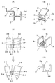
- (A) is a sectional view of a square frame block
- (B) is a perspective view of the square frame block
- (C) is a drawing showing a bending angle regulating projection of the square frame block
- (D) ) Is a perspective view showing a concave block
- (E) is a schematic side view of a state where a clamp is attached to the concave block at the tip.
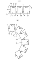
- the front view of the state which connected the said square frame block in series, (B) is a front view at the time of bending
- the exterior material 1 for the wire harness of 1st Embodiment is shown in FIG. 1 thru
- the exterior material 1 sequentially connects the plurality of square frame blocks 2 via the thin hinge portion 3 and at the one end in the length direction of the square frame block 2, the fixing block 4 consisting of a corrugated tube fitting block is hinged 3
- the concave block 5 consisting of a plurality of corrugated tube fitting blocks is connected to the other end through the hinge portion 3 at the other end.
- the sheathing material 1 is a caterpillar-type sheathing material in which a large number of blocks are sequentially connected via the hinge portion 3 and bent in one direction as a whole.
- the square frame block 2 has the configuration shown in FIGS. 2A to 2C and FIG. 3, and a plurality of square frame blocks 2 and hinges 3 are integrally formed.
- Each square frame block 2 is openably connected via the hinge portion 2e to the upper end of the right side frame 2a, the left side frame 2b, the lower frame 2c connecting the middle between the left and right side frames 2a and 2b in the height direction, and the left side frame 2b.
- the wire harness insertion space 2f of the hollow portion is surrounded by the upper frame 2d.
- the front and back are made into the openings 2g and 2h for wire harness penetration.
- the front and rear end faces of the left side frame and the right side frame provided with the openings 2g and 2h are connected to the adjacent square frame block 2 by the hinge portion 3.
- the hinge portion 3 is provided between the adjacent square frame blocks 2 at the position of the lower frame 2 c.
- the bending angle regulating projection 2m is directed to the square frame block 2-B adjacent to the left and right side frames 2b and 2a in the square frame block 2-A.
- a bending angle restricting projection 2n is provided on a square frame block 2-B between the square frame blocks 2-A.
- the bending angle restricting projection 2m provided on the square frame block 2-A is a triangle having a tapered surface 2m-b which is inclined downward from the projecting end of the upper surface 2m-a.
- the bending angle regulating projection 2n provided on the square frame block 2-B is a square.
- the tip of the upper surface 2m-a collides, and the tapered surface 2m-b of the rectangular frame block 2-A contacts the vertical surface 2n-b of the rectangular frame block 2-B, thereby causing the structure shown in FIG.
- the bending radius of the exterior material 1 shown is specified.
- the bending angle restricting projections 2n of the square frame block 2-B may also be triangular like the bending angle restricting projections 2m, but there is a fear that bending fatigue may occur in the wire harness inserted inside due to rapid bending. Because of this, in the present embodiment, the bending angle regulating projection 2n is in the shape of a quadrilateral.
- the upper frame 2d of the adjacent square frame blocks 2-A and 2-B is bent at the time of bending.
- the front and back facing surfaces of the lower frame 2c are bent in one direction until the bending angle restricting projections 2m and 2n contact each other.
- the lock claw 2r1 is provided at the tip of the upper frame 2d of the rectangular frame block 2 (2-A, 2-B), the lock frame 2r2 is provided at the upper part of the outer surface of the right frame 2a.
- the wire harness is inserted into the square frame block 2, as shown in FIG. 2A, the upper frame 2d is opened, the wire harness is inserted and closed, and the lock claw 2r1 at the tip of the upper frame 2d is the right frame
- the lock frame 2r2 of 2a is inserted and locked to be locked.
- Concave blocks 5 are connected.
- three concave blocks 5 are connected via the hinge portion 3.
- These concave blocks 5 are provided with left and right side frames 5b and 5a and a lower frame 5c, there is no upper frame, and the upper surface is an opening 5f.
- an arc shape is formed from the inner surface of the lower frame 5c to the lower inner surfaces of the left and right frames 5b, 5a, and the uneven portion 5e is provided on the arc surface.
- the uneven portion 5e is fitted to the ridges 21a and the valleys 21b of the outer peripheral surface of the corrugated tube 21 (21-A) which is externally fitted to the wire harness 20 shown in FIG. 1 (C).
- the concave block 5-A at the tip is a fixing block, and the clamp 25 is rotated on the left frame 5b as shown in FIG. 2 (E). It is attached via a shaft 25a, and the clamp 25 is rotatably fixed to a workpiece 23 (in the second embodiment, a luggage arm).
- the concave block 5, which serves as the corrugated tube fitting block, has the opening 5f on the upper surface, so that the corrugate tube 21-A, which is fitted inside, can be detached to the outside through the opening 5f when the workpiece 23 rotates.
- the corrugated tube 21-A pulled out from the concave block 5-A for fixing the tip has the tape 28 wound and attached at a position forward of the concave block 5-A.
- the corrugated tube 21-A separated from the concave block 5 is configured to return into the concave block 5 through the opening 5f of the concave block 5 when the workpiece 23 returns to the original position.
- the fixed block 4 made of a corrugated tube fitting block is connected through the thin hinge portion 3 to the rear end in the longitudinal direction of the region Z1 in which the square frame block 2 is sequentially connected through the hinge portion 3 ing.
- the fixed block 4 includes the left and right side frames 4b and 4a, the lower frame 4c, and the openable and closable upper frame 4d like the square frame block 2, and the inner surface of the lower frame 4c and the left and right side frames 4b and 4a has an arc shape and is corrugated.
- An uneven portion 4e fitted to the peak portion 21a and the valley portion 21b of the tube 21-B is provided.
- the fixing block 4 encloses the corrugated tube 21-B with a square frame so that it can not be detached. And, the bracket 6 for vehicle body locking is connected to the right side frame 4b of the fixed block 4, and a locking piece (not shown) protrudingly provided on the vehicle body etc. is inserted into the locking hole of the bracket 6 and locked. The rear end of the exterior material 1 can be fixed to the vehicle body.
- the caterpillar-type exterior material 1 having the above-described configuration does not cover the area Z1 where the bending direction of the wire harness 20 needs to be restricted with the corrugated tube, and the inside of the square frame block 2
- the wire group of the wire harness 20 is inserted, and the front region Z2 and the rear side thereof are covered with corrugated tubes 21-A and 21-B.
- the corrugated tube 21 -A is fitted and passed in the concave block 5, and the corrugated tube 21 -B is fitted in the fixed block 4.
- the wire harness 20 which is covered with the exterior material 1 is wired in a vehicle, and the fixing block 4 at the rear end is fixed to the vehicle body via the bracket 6, and the concave block 5-A for fixing the front end is rotationally operated. It fixes to the mounting material 23. That is, only by fixing both ends in the length direction of the exterior material 1 to the mounting material of the vehicle body and the operation member, the exterior material 1 between them is not fixed to the mounting material 23. It is apart from the bending action in its own form.
- the wire harness 20 extends from the portion covered with the corrugated tube 21 -A to the fixing point P1 with the attachment material 23 as indicated by the dashed dotted line in the figure. As shown in FIG. 1, it can be separated from the concave block 5 of the exterior material 1 and bent. Furthermore, since the exterior material 1 has the fixing block 4 at the front end attached to the mounting material 23 rotatably via the rotary shaft 25a with the fixing block 4 at the rear end as a fulcrum, the intermediate square The frame block 2 and the concave block 5 can also be detached from the workpiece 23 and can be bent together with the inserted wire harness 20.
- the exterior material 1 of the first embodiment has the concave block 5 connected to the front end of the square frame block 2 so that the corrugated tube 21 -A can be detached from the exterior material 1.
- the corrugated tube fitting block of the same square frame may be used in place of the concave block 5 so that the corrugated tubes on both sides can not be detached from the sheathing material 1.
- the wire harness 20 covered with the exterior material 1 of the first embodiment is routed from the luggage room 30 of the automobile shown in FIG. 5 along the luggage arm 31 to the luggage door 32.
- one end of the luggage arm 31 is rotatably connected to the vehicle body panel 36 surrounding the luggage room 30 via the rotational support shaft 37, and the luggage door 32 is opened and closed (shown by thin lines). In operation (shown by solid lines), it rotates as shown in FIGS. 6 and 7.
- the substantially U-shaped luggage arm 31 supporting the luggage door 32 has a rectangular frame shape in cross section, and the exterior material 1 is disposed along the inner side of the luggage arm 31.
- the wire harness 20 packaged with the exterior material 1 rotatably attaches a concave block 5-A for fixing the front end of the concave block 5 of the exterior material 1 to the luggage arm 31 via the clamp 25, and
- the bracket 6 connected to the fixed block 4 is fixed to the vehicle body (upper wall corner surrounding the luggage room 30) in the vicinity of the vehicle side rotation supporting point of the luggage arm 31.
- the corrugated tube 21-B is externally fitted to a wire harness 20 wired from the vehicle body side to the fixed block 4, and the corrugated tube 21-B is fitted to and connected to the fixed block 4 from the fixed block 4 to a square frame block After the wire harness 20 is penetrated to the No. 2, the corrugated tube 21 -A is put on the wire harness 20 and fitted in the concave block 5.
- the wire harness 20 is routed inside the side frame of the luggage door 32 Are connected to electrical components attached to the luggage door 32.
- the rear end of the exterior material 1 is fixed to the vehicle body, while the front end is rotatably attached to the luggage arm 31, and it is not fixed to the luggage arm 31 in the meantime and can be operated separately from the luggage arm 31.
- the corrugated tube 21-B is externally fitted and held on the fixed block 4 on the vehicle body side on the rear side, passes through the square frame block 2, passes through the concave block 5, and then , Fixed to the luggage arm 31 in front of the remote position. Therefore, until it passes square frame block 2 from the back end of exterior material 1, it bends in conjunction with exterior material 1, operates to bend, exits square frame block 2 and adheres to luggage arm 31 ahead from concave block 5 It can operate freely to the position.
- the exterior material 1 is attached to the luggage arm 31, and the wire harness 20 exteriorized with the exterior material 1 is disposed along the luggage arm 31 as described above.
- the luggage door 32 is opened and closed, as shown in FIGS. 6 and 7, the vehicle attachment side of the luggage arm 31 operates to enter the luggage room 30 at a large rotation angle.
- the exterior material 1 also operates according to the operation of the luggage arm 31, but since the front end of the exterior material 1 is rotatably connected to the luggage arm 31, the vehicle-body-side fixing point of the rear end and the front end are rotatably fixed. As shown in FIGS. 6 and 7 between the points, they move away from the luggage arm 31, curve outward and follow, and do not enter the luggage room 30.
- the exterior material 1 can be bent only in one direction of the drawing by the square frame block 2 and the bending angle is regulated by the contact of the bending angle regulating projections 2 n and 2 m provided on the square frame block 2. 1 is defined to bend as shown.
- the recess of the exterior material 1 is recessed.
- the shape block 5 is bent out at a gentle angle to follow the rotational operation of the luggage arm 31 as shown in FIGS.
- the S-shaped bending of the wire harness 20 is performed outward from the luggage arm 31 entering the luggage room 30, and the wire harness 20 also does not enter the luggage room 30.
- the luggage arm 31 which is rotationally operated when the luggage door 32 is opened and closed operates so as to largely enter the luggage room 30, but the exterior material 1 and the wire harness 20 are separated from the luggage arm 31.
- the working range is smaller than that of the luggage arm 31, and the bending of the wire harness 20 is also made gentle.
- the wire harness 20 follow-up operations can be made into a narrow range, and bending fatigue can be reduced by performing at a gentle bending angle.
- the exterior material for the wire harness of the present invention can be applied to a wire harness to be wired to a member that operates to reciprocate, as well as the wire harness for supplying power to the luggage door of the second embodiment.
Landscapes
- Engineering & Computer Science (AREA)
- Architecture (AREA)
- Civil Engineering (AREA)
- Structural Engineering (AREA)
- Mechanical Engineering (AREA)
- Details Of Indoor Wiring (AREA)
- Electric Cable Arrangement Between Relatively Moving Parts (AREA)
Abstract
ラゲージアームに沿って配索するワイヤハーネス等に好適に用いられる外装材を提供する。上下枠と左右側枠でワイヤハーネス挿通空間を囲む四角枠ブロックをヒンジ部を介して順次連結し、前記四角枠ブロックの前後面を開口としてワイヤハーネス挿通口とし、前記ヒンジ部は隣接する前記四角枠ブロック間で前記左右側枠を連結する位置に設け、かつ、前記ヒンジ部による連結位置の下部に、隣接する四角枠ブロックに向けて互いに突出する曲げ角度規制突起を設け、少なくとも一方の曲げ角度規制突起は上面の突出端より下向きに傾斜するテーパ面を備えた三角形とし、前記四角枠ブロックが直線状に連結される状態で、隣接する前記曲げ角度規制突起の上面同士が互いに接触する一方、前記ヒンジ部を介して前記四角枠ブロックが湾曲して連結される際、曲げ角度規制突起のテーパ面が接触する位置で所要の曲げアールとなる設定としている。
Description
本発明はワイヤハーネス用の外装材および該外装材を用いたワイヤハーネスの配索構造に関し、詳しくは、ワイヤハーネスを取り付ける被取付部材の回転時に追従作動するワイヤハーネスに好適に用いられるものである。
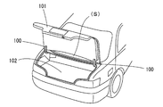
自動車の後部に設けられるラゲージルーム(荷物室)は、特開2013-212795号公報等で、図8に示されるように、略U字状に湾曲したヒンジアーム(以下、ラゲージアームと称す)100を用いてラゲージドア101とラゲージルーム102の上端壁を連結し、ラゲージドア101を開くと、左右のラゲージアーム100によりラゲージドア101が支持されて、該ラゲージドア101がラゲージルーム102との間に空間(S)をあけた状態で開放され、ラゲージルーム102内への荷物の挿入および取り出しが容易とされている。
前記ラゲージドア101にはドア開閉用のスイッチ、ナンバー照明ランプ等の電装品が搭載されているため、ラゲージアーム100に沿って車体側からラゲージドア101へ給電用のワイヤハーネスが配索されている。
具体的には、ラゲージアーム100の側面にプロテクタを固定し、ラゲージルーム102を囲む上壁側隅部に設けたワイヤハーネス取出口から引き出したワイヤハーネスを前記プロテクタ内を貫通させ、ラゲージドア101の側枠の内部を通して前記スイッチ等へ接続している。
具体的には、ラゲージアーム100の側面にプロテクタを固定し、ラゲージルーム102を囲む上壁側隅部に設けたワイヤハーネス取出口から引き出したワイヤハーネスを前記プロテクタ内を貫通させ、ラゲージドア101の側枠の内部を通して前記スイッチ等へ接続している。
前記ラゲージルームを囲む車体側の引出口からラゲージアーム100の側面に固定したプロテクタを貫通してラゲージドアの側枠内部に引き出されるワイヤハーネスの配索領域では、ラゲージドアの開閉時にラゲージアームが回動するため、該ラゲージアームの回動にワイヤハーネスを追従させる必要がある。そのため、ワイヤハーネスを屈曲自在なコルゲートチューブあるいは柔軟性を有するシートで外装している。
前記ラゲージドアを支持するラゲージアームの回転に応じて、ワイヤハーネスがU字状あるいはS字状に屈曲しながら追従移動する。該ワイヤハーネスの外装材として、コルゲートチューブあるいは柔軟性を有するシートを用いると、ワイヤハーネスの屈曲方向を確実に規制できず、屈曲方向にバラツキが発生しやすい。よって、周辺に金属エッジ等があると干渉し、外装材および電線被覆を金属エッジが突き破って短絡や断線を発生する恐れがある。
また、ワイヤハーネスがU字状に屈曲する場合、ワイヤハーネスの屈曲が少ない点で有利であるが、屈曲範囲のスペースが大きくなり、設置スペースを取る問題がある。一方、S字状にワイヤハーネスが屈曲する場合、屈曲スペースを小さくできるが、屈曲が多いためワイヤハーネスに屈曲疲労が発生しやすい問題がある。
本発明は前記問題に鑑みてなされたもので、ワイヤハーネスをラゲージアーム等の被取付材の回転移動に応じて屈曲させて追従させる必要がある場合、ワイヤハーネスの曲げ角度を規制できるようにし、かつ、移動スペースを小さくして限られたスペースでワイヤハーネスを追従移動可能とし、さらに、ワイヤハーネスに屈曲疲労が発生しないワイヤハーネス用の外装材を提供することを課題としている。
さらに、本発明は、ラゲージドアを開閉自在に支持するラゲージアームに沿わせてラゲージルーム側からラゲージドアへ配索するワイヤハーネスの作動スペースの減少およびワイヤハーネスの疲労を減少できるワイヤハーネスの配索装置を提供することを課題としている。
さらに、本発明は、ラゲージドアを開閉自在に支持するラゲージアームに沿わせてラゲージルーム側からラゲージドアへ配索するワイヤハーネスの作動スペースの減少およびワイヤハーネスの疲労を減少できるワイヤハーネスの配索装置を提供することを課題としている。
前記課題を解決するため、第1の発明として、上下枠と左右側枠でワイヤハーネス挿通空間を囲む四角枠ブロックをヒンジ部を介して順次連結し、前記四角枠ブロックの前後面を開口としてワイヤハーネス挿通口とし、
前記ヒンジ部は隣接する前記四角枠ブロック間で前記左右側枠を連結する位置に設け、 かつ、前記ヒンジ部の下部に、隣接する四角枠ブロックに向けて互いに突出する曲げ角度規制突起を設け、少なくとも一方の曲げ角度規制突起は上面の突出端より下向きに傾斜するテーパ面を備えた三角形とし、
前記ヒンジ部を介して前記四角枠ブロックが湾曲して連結される際、前記曲げ角度規制突起のテーパ面が接触する位置で所要の曲げアールとなる設定としているワイヤハーネス用の外装材を提供している。
前記ヒンジ部は隣接する前記四角枠ブロック間で前記左右側枠を連結する位置に設け、 かつ、前記ヒンジ部の下部に、隣接する四角枠ブロックに向けて互いに突出する曲げ角度規制突起を設け、少なくとも一方の曲げ角度規制突起は上面の突出端より下向きに傾斜するテーパ面を備えた三角形とし、
前記ヒンジ部を介して前記四角枠ブロックが湾曲して連結される際、前記曲げ角度規制突起のテーパ面が接触する位置で所要の曲げアールとなる設定としているワイヤハーネス用の外装材を提供している。
前記四角枠ブロックが直線状に連結される状態で、隣接する前記曲げ角度規制突起の上面同士が互いに接触する一方、屈曲時には、隣接する四角枠ブロックは上枠の対向面が互いに開くと共に前記曲げ角度規定突起の下部の対向面が互いに近接する一方向にのみ屈曲するキャタピラ型の外装材としている。
前記構成とした外装材は、ヒンジ部を介して順次連結した四角枠ブロックが一方向に屈曲するキャタピラ型の外装材であるため、ワイヤハーネスの屈曲方向を規制でき、さらに、前記曲げ角度規制突起により曲げ角度も規制できる。よって、ワイヤハーネスの配索スペースを特定範囲に規制できると共に、周辺機器の金属エッジ等との接触で電線に損傷等が発生するのを防止できる。
前記三角形状とした曲げ角度規制突起はヒンジ部を介して順次連結する四角枠ブロックの全部に設けても良いし、一つ飛びに連結する四角枠ブロックに設け、その間の四角枠ブロックには四角形状とした曲げ角度規制突起を設けてもよい。
例えば、三角形状とした曲げ角度規制突起のテーパ面の傾斜角度が鋭角であると、該テーパ面同士が接触する際の曲げ角度は大きくなり過ぎる恐れがある。よって、隣接する一方の曲げ角度規制突起を三角形とすると共に他方を四角形とし、三角形としたテーパ面の傾斜角度を調節すると、外装材全体の曲げ角度を使用条件に適した角度に容易に調整することができる。
前記各四角枠ブロックは、左右側枠の一方に上枠を薄肉ヒンジ部を介して開閉自在に連結し、ワイヤハーネス挿通時に上枠を開き、挿通後に閉鎖し、上枠先端と左右側枠の他方枠とに設けたロック爪とロック枠とをロック結合することが好ましい。
第2の発明として、複数の四角枠ブロックをヒンジ部を介して順次連結していると共に、該連結した四角枠ブロックの長さ方向両端にヒンジ部を介してコルゲートチューブ嵌合ブロックを連結し、該コルゲートチューブ嵌合ブロックの内面にコルゲートチューブ嵌合用の凹凸部を設けているワイヤハーネス用の外装材を提供している。
該第2の発明の外装材は、ワイヤハーネスの配索経路の一部領域が屈曲方向を厳しく規制する必要があり、当該領域を挟む両側は屈曲方向を特に規制する必要がない場合に好適に用いられる。即ち、屈曲方向を規制する必要がある領域のワイヤハーネスはコルゲートチューブで外装せずに、ワイヤハーネスの電線群を前記四角枠ブロックに通して外装し、その両側のワイヤハーネスをコルゲートチューブで外装し、該コルゲートチューブを前記コルゲートチューブ嵌合ブロックの凹凸部に嵌合固定して、簡単に外装できるものとしている。
前記コルゲートチューブ嵌合ブロックのうち、少なくとも一方端に連結するコルゲートチューブ嵌合ブロックは、四角枠ブロックの一辺を開口とした凹形ブロックとし、該凹形ブロックの開口から嵌合するコルゲートチューブを離脱可能としている。
前記第2の発明の外装材の前記四角枠ブロックを順次ヒンジ部を介して連結した部分は前記第1の発明の外装材を用いることが好ましい。
前記凹形ブロックは、前記四角枠ブロックの上枠を無くして開口とし、少なくとも下枠の内面にコルゲートチューブの山谷に嵌合する前記凹凸部を設けている。なお、左右両側枠の内面にもコルゲートチューブの山谷に嵌合する凹凸部を設けてもよい。
また、他端側の固定ブロックは四角枠ブロックを構成する下枠の内面に、嵌合するコルゲートチューブの山谷に嵌合する凹凸部を設けている。該固定ブロックも左右両側枠の内面および上枠の内面にもコルゲートチューブの山谷に嵌合する凹凸部を設けてもよい。
前記凹形ブロックは、前記四角枠ブロックの上枠を無くして開口とし、少なくとも下枠の内面にコルゲートチューブの山谷に嵌合する前記凹凸部を設けている。なお、左右両側枠の内面にもコルゲートチューブの山谷に嵌合する凹凸部を設けてもよい。
また、他端側の固定ブロックは四角枠ブロックを構成する下枠の内面に、嵌合するコルゲートチューブの山谷に嵌合する凹凸部を設けている。該固定ブロックも左右両側枠の内面および上枠の内面にもコルゲートチューブの山谷に嵌合する凹凸部を設けてもよい。
前記第2の発明の外装材も、四角枠ブロックを薄肉ヒンジ部を介して順次連結した領域は、一方向にのみ屈曲するキャタピラ型の外装材としている。
よって、第1の発明のキャタピラ型の外装材と同様に、ワイヤハーネスの屈曲方向を規制でき、よって、ワイヤハーネスの配索スペースを特定できると共に、周辺機器の金属エッジ等と接触して電線に損傷が発生するのを防止できる。
さらに、前記四角枠ブロックの一辺を開口した前記凹形ブロックを連続させ、ワイヤハーネスに外装したコルゲートチューブを凹形ブロックから離脱できる構成としているため、該外装材を取り付けたラゲージアーム等の屈曲した被取付材の回転に追従してワイヤハーネスが移動する際、急角度で複雑に屈曲する領域では、外装材からワイヤハーネスが離脱して、緩やかな角度で屈曲すると共に狭い範囲で屈曲して、被取付材の回転に追従させることができる。これにより、ワイヤハーネスの屈曲疲労の低減およびワイヤハーネスの作動スペースの低減を図ることができる。
よって、第1の発明のキャタピラ型の外装材と同様に、ワイヤハーネスの屈曲方向を規制でき、よって、ワイヤハーネスの配索スペースを特定できると共に、周辺機器の金属エッジ等と接触して電線に損傷が発生するのを防止できる。
さらに、前記四角枠ブロックの一辺を開口した前記凹形ブロックを連続させ、ワイヤハーネスに外装したコルゲートチューブを凹形ブロックから離脱できる構成としているため、該外装材を取り付けたラゲージアーム等の屈曲した被取付材の回転に追従してワイヤハーネスが移動する際、急角度で複雑に屈曲する領域では、外装材からワイヤハーネスが離脱して、緩やかな角度で屈曲すると共に狭い範囲で屈曲して、被取付材の回転に追従させることができる。これにより、ワイヤハーネスの屈曲疲労の低減およびワイヤハーネスの作動スペースの低減を図ることができる。
前記四角枠ブロックの連結部の一方端に複数の前記凹形ブロックをヒンジ部を介して順次連結し、連結部分の先端の凹形ブロックを被取付材への固定ブロックとする一方、
前記四角枠ブロックの連結部の他方端に四角枠ブロックの内面に前記コルゲートチューブ嵌合用の凹凸部を設けた1つの固定ブロックをヒンジ部を介して連結し、該固定ブロックおよび前記凹形ブロックの固定ブロックに、被取付材に取り付ける固定用クランプ、固定用ブラケットまたは粘着テープ巻付片を突設することが好ましい。
前記四角枠ブロックの連結部の他方端に四角枠ブロックの内面に前記コルゲートチューブ嵌合用の凹凸部を設けた1つの固定ブロックをヒンジ部を介して連結し、該固定ブロックおよび前記凹形ブロックの固定ブロックに、被取付材に取り付ける固定用クランプ、固定用ブラケットまたは粘着テープ巻付片を突設することが好ましい。
前記のように、外装材の長さ方向の両端を被取付材へ取り付ける固定ブロックとし、両端の固定ブロックで挟まれた中間領域は被取付材に固定しない構成とすると、被取付材が屈曲形状で且つ作動時に複雑な屈曲作動をしても、外装材の中間部は被取付材の作動に追従せずに、狭い作動範囲で且つ緩やかに屈曲させて追従させることができる。
さらに、第3の発明として、前記第2の発明のワイヤハーネスの外装材を、自動車のラゲージドアに配索するワイヤハーネスに外装し、前記外装材および前記ワイヤハーネスをラゲージアームに沿って配索しているワイヤハーネスの配索構造を提供している。
詳しくは、前記第2の発明の外装材の凹形ブロック側の一端の前記固定ブロックを、U字状のラゲージアームに回転自在に固定すると共に、他端側の前記固定ブロックを前記ラゲージアームの車体側回転支点の近傍の車体に固定し、該固定ブロックに車体側から配索するワイヤハーネスにコルゲートチューブを外装して嵌合し、該固定ブロックから前記四角枠ブロックにワイヤハーネスを貫通させた後に、該ワイヤハーネスにコルゲートチューブを外装して前記凹形ブロックに嵌合し、該凹形ブロックの先端から引き出す前記ワイヤハーネスを前記ラゲージアームに取り付けた後に、該ワイヤハーネスをラゲージドアの側枠に配索して、該ラゲージドアに取り付けた電装品に接続している。
前記ラゲージドアを支持する前記略U字形状のラゲージアームは断面四角枠状とし、該ラゲージアームの一辺に前記外装材の凹形ブロック側の一端の固定ブロックを回転自在に取り付けている。よって、ラゲージドアの閉作動時にラゲージアームの車体取付側は大きな回転角度でラゲージルーム内に入り込むように作動し、該ラゲージアームの作動に前記外装材は追従するが、該外装材の凹形ブロックからコルゲートチューブで外装したワイヤハーネスの部分が離脱し、ラゲージルーム内へラゲージアームが大きく入り込む部分でワイヤハーネスは追従せず、ワイヤハーネスの車体側の固定点からラゲージアームの係止点の間のワイヤハーネスは狭い範囲で緩やかにS字状に屈曲させることができる。
前記のように、ラゲージアームの回転動作に、前記外装材の中間部分および該外装材で外装したワイヤハーネスの一部を離脱させて追従させる構成とすることで、該ワイヤハーネスの追従動作を狭い範囲で且つ緩やかな屈曲角度で行わせることができる。
前記第1の発明のワイヤハーネス用の外装材は、四角枠ブロックをヒンジ部を介して連結したキャタピラ型の外装材において、屈曲時の曲げアールを簡単に設定でき、該外装材で外装するワイヤハーネスの屈曲作動範囲を規定することができる。
また、前記第2の発明のワイヤハーネス用の外装材は、四角枠ブロックの前後にコルゲートチューブ嵌合ブロックをヒンジ部を介して連結しているため、曲げ方向を規制する必要がある領域のワイヤハーネスを前記四角枠ブロックに挿通し、曲げ方向を厳格に規制する必要がない領域のワイヤハーネスをコルゲートチューブで外装し、該コルゲートチューブを前記外装材で簡単に外装することができる。
さらに、前記第3の発明のワイヤハーネスの配索構造では、複雑な回転作動をすると共に閉じ位置でラゲージルーム内に大きく入り込むラゲージアームに沿わせて配索するワイヤハーネスを、前記外装材で外装することで、作動範囲を減少できると共に、緩やかな屈曲としてワイヤハーネスの屈曲疲労を低減することができる。
以下、本発明の実施形態を図面を参照して説明する。
図1乃至図4に第1実施形態のワイヤハーネス用の外装材1を示す。
該外装材1は、図5乃至図7に示す第2実施形態において後述するように、自動車のラゲージルームを開閉するラゲージドアに設置した電装品に、ラゲージルームからラゲージアームに沿わせて配索する給電用のワイヤハーネス20に外装している。
図1乃至図4に第1実施形態のワイヤハーネス用の外装材1を示す。
該外装材1は、図5乃至図7に示す第2実施形態において後述するように、自動車のラゲージルームを開閉するラゲージドアに設置した電装品に、ラゲージルームからラゲージアームに沿わせて配索する給電用のワイヤハーネス20に外装している。
外装材1は複数の四角枠ブロック2を薄肉のヒンジ部3を介して順次連結すると共に、該四角枠ブロック2の長さ方向の一端にコルゲートチューブ嵌合ブロックからなる固定ブロック4をヒンジ部3を介して連結すると共に、他端に複数のコルゲートチューブ嵌合ブロックからなる凹形ブロック5をヒンジ部3を介して連結している。外装材1は前記のように多数のブロックをヒンジ部3を介して順次連結し、全体として一方向に屈曲するキャタピラ型の外装材としている。
四角枠ブロック2は図2(A)~(C)および図3に示す構成で、複数の四角枠ブロック2およびヒンジ部3を一体成形で設けている。各四角枠ブロック2は、右側枠2a、左側枠2b、左右側枠2aと2bの高さ方向の中間を連結する下枠2c、左側枠2bの上端にヒンジ部2eを介して開閉自在に連結した上枠2dで、中空部のワイヤハーネス挿通空間2fを囲んでいる。前後はワイヤハーネス挿通用の開口2g、2hとしている。
該開口2g、2hを備えた左側枠および右側枠の前後端面を、隣接する四角枠ブロック2と前記ヒンジ部3で連結している。該ヒンジ部3は隣接する四角枠ブロック2間で、下枠2cの位置に設けている。かつ、ヒンジ部3により連結する四角枠ブロック2には一つ飛びの四角枠ブロック2-Aに、左右側枠2b、2aより隣接する四角枠ブロック2ーBに向けて曲げ角度規制突起2mを突設する一方、四角枠ブロック2-Aの間の四角枠ブロック2-Bに曲げ角度規制突起2nを設けている。
四角枠ブロック2-Aに設ける前記曲げ角度規制突起2mは上面2m-aの突出端より下方に向かって傾斜するテーパ面2m-bを備えた三角形としている。一方、四角枠ブロック2-Bに設ける曲げ角度規制突起2nは四角形としている。このように、曲げ角度規制突起2mと2nを対向して設け、外装材1が屈曲した際、曲げ角度規制突起2nの上面2n-aの先端に四角枠ブロック2-Aの曲げ角度規制突起2mの上面2m-aの先端が衝突し、該四角枠ブロック2ーAのテーパ面2m-bが四角枠ブロック2-Bの縦面2n-bに接触し、これにより、図3(C)に示す外装材1の曲げアールを規定している。
なお、四角枠ブロック2-Bの曲げ角度規制突起2nも、曲げ角度規制突起2mと同様に三角形状としてもよいが、急激曲げになって、内部を挿通するワイヤハーネスに屈曲疲労が発生する恐れがあるため、本実施形態では、曲げ角度規制突起2nを四角形状としている。
四角枠ブロック2-Aと2-Bとをヒンジ部3を介して前後方向に交互に連結している領域Z1では、屈曲時に、隣接する四角枠ブロック2-Aと2-Bの上枠2dの前後対向面が互いに開くと共に、下枠2cの前後対向面は曲げ角度規制突起2mと2nとが接触するまで一方向に屈曲する。
前記四角枠ブロック2(2-A、2-B)の上枠2dの先端にロック爪2r1を設ける一方、右側枠2aの外面上部にロック枠2r2を設けている。
該四角枠ブロック2にワイヤハーネスを挿通する時、図2(A)に示すように、上枠2dを開き、ワイヤハーネスを挿入後に閉鎖して、上枠2dの先端のロック爪2r1を右側枠2aのロック枠2r2に挿入係止してロック結合するものとしている。
該四角枠ブロック2にワイヤハーネスを挿通する時、図2(A)に示すように、上枠2dを開き、ワイヤハーネスを挿入後に閉鎖して、上枠2dの先端のロック爪2r1を右側枠2aのロック枠2r2に挿入係止してロック結合するものとしている。
前記四角枠ブロック2をヒンジ部3を介して順次連結している領域Z1の長さ方向の前端に連続する領域Z2に、前記のように、薄肉のヒンジ部3を介してコルゲートチューブ嵌合ブロックの凹形ブロック5を連結している。本実施形態では3個の凹形ブロック5をヒンジ部3を介して連結している。これら凹形ブロック5は左右側枠5b、5aと下枠5cを備え、上枠は無く、上面を開口5fとしている。また、下枠5cの内面から左右側枠5b、5aの下部内面にかけて円弧形状とし、該円弧面に凹凸部5eを設けている。この凹凸部5eは、図1(C)に示すワイヤハーネス20に外装するコルゲートチューブ21(21-A)の外周面の山部21aと谷部21bに嵌合するものである。
ヒンジ部3を介して順次連結する前記凹形ブロック5のうち、先端の凹形ブロック5-Aは固定用ブロックとし、その左枠5bに図2(E)に示すように、クランプ25を回転軸25aを介して取り付け、該クランプ25を被取付材23(第2実施形態ではラゲージアーム)に回転自在に固定している。
該コルゲートチューブ嵌合ブロックとする凹形ブロック5は上面を開口5fとしているため、被取付材23が回転移動をする際に、内嵌するコルゲートチューブ21ーAは開口5fを通して外部へ離脱可能としている。
前記先端の固定用の凹形ブロック5-Aから引き出されるコルゲートチューブ21ーAは、該凹形ブロック5-Aから前方の離れた位置にテープ28を巻きつけて取り付けている。凹形ブロック5から離脱するコルゲートチューブ21-Aは被取付材23が元の位置に戻った時に、凹形ブロック5の開口5fを通して、該凹形ブロック5内に戻る構成としている。
前記先端の固定用の凹形ブロック5-Aから引き出されるコルゲートチューブ21ーAは、該凹形ブロック5-Aから前方の離れた位置にテープ28を巻きつけて取り付けている。凹形ブロック5から離脱するコルゲートチューブ21-Aは被取付材23が元の位置に戻った時に、凹形ブロック5の開口5fを通して、該凹形ブロック5内に戻る構成としている。
また、四角枠ブロック2をヒンジ部3を介して順次連結している領域Z1の長さ方向の後端に、薄肉のヒンジ部3を介してコルゲートチューブ嵌合ブロックからなる固定ブロック4を連結している。該固定ブロック4は四角枠ブロック2と同様に左右側枠4b、4a、下枠4c、開閉自在な上枠4dを備え、下枠4cおよび左右側枠4b、4aの内面を円弧形状とし、コルゲートチューブ21-Bの山部21aと谷部21bに嵌合する凹凸部4eを設けている。
前記固定ブロック4はコルゲートチューブ21-Bを四角枠で囲み、離脱できない構成としている。かつ、該固定ブロック4の右側枠4bに車体係止用のブラケット6を連結し、車体等に突設した係止片(図示せず)をブラケット6の係止穴に挿入係止して、外装材1の後端を車体に固定できるようにしている。
前記構成としたキャタピラ型の外装材1は、図1(C)に示すように、ワイヤハーネス20の屈曲方向を規制する必要がある領域Z1はコルゲートチューブで外装せずに、四角枠ブロック2内にワイヤハーネス20の電線群を挿通し、その前方領域Z2と後方の両側をコルゲートチューブ21-A、21-Bで外装している。コルゲートチューブ21-Aは凹形ブロック5内に嵌合して通し、コルゲートチューブ21-Bは固定ブロック4内に嵌合している。
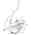
前記外装材1で外装したワイヤハーネス20を車両に配索し、後端の固定ブロック4をブラケット6を介して車体に固定すると共に、前端の固定用の凹形ブロック5-Aを回転作動する被取付材23に固定する。即ち、外装材1は長さ方向の両端を車体と作動部材の被取付材に固定しているだけで、その間の外装材1は被取付材23に固定していないため、被取付材23から離れて独自の形態で屈曲作動可能としている。
よって、図4に示すように、湾曲した被取付材23が回転作動する際、ワイヤハーネス20はコルゲートチューブ21-Aで外装した部分から被取付材23との固定点P1にかけて、図中一点鎖線で示すように外装材1の凹形ブロック5から離脱して屈曲できる。さらに、外装材1は後端の固定ブロック4を支点として、前端の固定用の凹形ブロック5-Aを回転軸25aを介して回転自在に被取付材23に取り付けているため、中間の四角枠ブロック2および凹形ブロック5も被取付材23から離脱して、挿通するワイヤハーネス20と共に屈曲作動させることができる。
なお、前記第1実施形態の外装材1は四角枠ブロック2の前端に凹形ブロック5を連続させて、コルゲートチューブ21-Aを外装材1から離脱可能としているが、後端の固定ブロック4と同様な四角枠のコルゲートチューブ嵌合ブロックを凹形ブロック5に代えて用い、両側のコルゲートチューブを外装材1から離脱できない構成としてもよい。
図5乃至図7に第2実施形態を示す。
第2実施形態は第1実施形態の外装材1で外装したワイヤハーネス20を、図5に示す自動車のラゲージルーム30からラゲージアーム31に沿わせてラゲージドア32に配索している。図6に示すように、ラゲージアーム31の一端はラゲージルーム30を囲む車体パネル36に回転支軸37を介して回転自在に連結しており、ラゲージドア32を開き位置(細線で示す)と閉じ位置(実線で示す)に作動する際に、図6および図7に示すように回転作動する。ラゲージドア32を支持する略U字形状のラゲージアーム31は断面四角枠状であり、該ラゲージアーム31の内側辺に外装材1を沿わせて配置している。
第2実施形態は第1実施形態の外装材1で外装したワイヤハーネス20を、図5に示す自動車のラゲージルーム30からラゲージアーム31に沿わせてラゲージドア32に配索している。図6に示すように、ラゲージアーム31の一端はラゲージルーム30を囲む車体パネル36に回転支軸37を介して回転自在に連結しており、ラゲージドア32を開き位置(細線で示す)と閉じ位置(実線で示す)に作動する際に、図6および図7に示すように回転作動する。ラゲージドア32を支持する略U字形状のラゲージアーム31は断面四角枠状であり、該ラゲージアーム31の内側辺に外装材1を沿わせて配置している。
外装材1で外装するワイヤハーネス20は、外装材1の凹形ブロック5の前端の固定用の凹形ブロック5-Aをラゲージアーム31にクランプ25を介して回転自在に取り付けると共に、後端の固定ブロック4に連結したブラケット6をラゲージアーム31の車体側回転支点の近傍の車体(ラゲージルーム30を囲む上壁隅部)に固定している。該固定ブロック4に車体側から配索するワイヤハーネス20にコルゲートチューブ21-Bを外装し、該コルゲートチューブ21-Bを固定ブロック4に嵌合して連結し、該固定ブロック4から四角枠ブロック2にワイヤハーネス20を貫通させた後に、ワイヤハーネス20にコルゲートチューブ21-Aを外装して凹形ブロック5に嵌合している。
凹形ブロック5の先端の固定用の凹形ブロック5-Aから引き出すワイヤハーネス20に固着した基板クランプ35をラゲージアーム31に取り付けた後に、ワイヤハーネス20をラゲージドア32の側枠内部に配索して、該ラゲージドア32に取り付けた電装品に接続している。
前記のように、外装材1の後端を車体に固定する一方、前端をラゲージアーム31に回転自在に取り付け、その間はラゲージアーム31に固定せず、ラゲージアーム31と別作動可能としている。また、外装材1で外装したワイヤハーネス20は後側の車体側では固定ブロック4にコルゲートチューブ21-Bが外嵌保持され、四角枠ブロック2を通した後に、凹形ブロック5を通り、その後、離れた位置の前方でラゲージアーム31に固定している。よって、外装材1の後端から四角枠ブロック2を通過するまでは、外装材1と連動して屈曲作動し、四角枠ブロック2を出て凹形ブロック5から前方のラゲージアーム31との固着位置までフリーに作動できる。
前記のように、外装材1をラゲージアーム31に取り付けると共に、該外装材1で外装したワイヤハーネス20を前記のようにラゲージアーム31に沿わせて配置している。
ラゲージドア32の開閉作動時に図6および図7に示すように、ラゲージアーム31の車体取付側は大きな回転角度でラゲージルーム30内に入り込むように作動する。
ラゲージドア32の開閉作動時に図6および図7に示すように、ラゲージアーム31の車体取付側は大きな回転角度でラゲージルーム30内に入り込むように作動する。
該ラゲージアーム31の作動に応じて外装材1も作動するが、ラゲージアーム31に外装材1の前端を回転自在に連結しているため、後端の車体側固定点と前端の回転自在な固定点の間で図6、図7に示すように、ラゲージアーム31から離れて、外向きに湾曲して追従し、ラゲージルーム30内に入り込まない。この外装材1の屈曲は、四角枠ブロック2により図示の一方向にのみ屈曲できると共に四角枠ブロック2に設けた曲げ角度規制突起2n、2mの接触で曲げ角度を規制しているため、外装材1は図示のように屈曲するように規定される。
かつ、前記のように、ラゲージルーム30に入り込まないように屈曲する外装材1に対して、その内部に挿通するワイヤハーネス20は前方でラゲージアーム31に固着されているため、外装材1の凹形ブロック5から外れて図6および図7に示すように緩やかな角度でS字屈曲してラゲージアーム31の回転作動に追従する。このワイヤハーネス20のS字屈曲はラゲージルーム30に入り込むラゲージアーム31より外方でなされ、ワイヤハーネス20もラゲージルーム30内に入り込むことはない。
前記のように、ラゲージドア32の開閉時に回転作動するラゲージアーム31はラゲージルーム30内に大きく入り込むように作動するが、外装材1およびワイヤハーネス20はラゲージアーム31とは離反して、ラゲージルーム30内に大きく入りこまず、作動範囲はラゲージアーム31より小さく、かつ、ワイヤハーネス20の屈曲も緩やかになされる。
このように、ラゲージアーム31の回転動作に、外装材1および該外装材1で外装したワイヤハーネス20の一部を離脱させて小さい範囲内での屈曲作動で追従させる構成としているため、ワイヤハーネス20の追従動作を狭い範囲とでき、かつ、緩やかな屈曲角度で行わせて屈曲疲労を低減することができる。
本発明のワイヤハーネス用の外装材は、第2実施形態のラゲージドアへの給電用のワイヤハーネス以外にも、往復回転作動する部材に配索するワイヤハーネスに適用することができる。
1 外装材
2 四角枠ブロック
2m、2n 曲げ角度規制突起
3 ヒンジ部
4 固定ブロック
5 凹形ブロック
5-A 固定用の凹型ブロック
20 ワイヤハーネス
21-A、21-B コルゲートチューブ
30 ラゲージルーム
31 ラゲージアーム
32 ラゲージドア
2 四角枠ブロック
2m、2n 曲げ角度規制突起
3 ヒンジ部
4 固定ブロック
5 凹形ブロック
5-A 固定用の凹型ブロック
20 ワイヤハーネス
21-A、21-B コルゲートチューブ
30 ラゲージルーム
31 ラゲージアーム
32 ラゲージドア
Claims (8)
- 上下枠と左右側枠でワイヤハーネス挿通空間を囲む四角枠ブロックをヒンジ部を介して順次連結し、前記四角枠ブロックの前後面を開口としてワイヤハーネス挿通口とし、
前記ヒンジ部は隣接する前記四角枠ブロック間で前記左右側枠を連結する位置に設け、
かつ、前記ヒンジ部の下部に、隣接する四角枠ブロックに向けて互いに突出する曲げ角度規制突起を設け、少なくとも一方の曲げ角度規制突起は上面の突出端より下向きに傾斜するテーパ面を備えた三角形とし、
前記ヒンジ部を介して前記四角枠ブロックが湾曲して連結される際、前記曲げ角度規制突起のテーパ面が接触する位置で所要の曲げアールとなる設定としているワイヤハーネス用の外装材。 - 前記四角枠ブロックは、上枠を左右側枠の一方に薄肉ヒンジ部を介して開閉自在に連結して、ワイヤハーネス挿通時に上枠を開き、挿通後に閉鎖して、上枠先端と左右側枠の他方枠とに設けたロック爪とロック枠とをロック結合する構成としている請求項1に記載のワイヤハーネス用の外装材。
- 複数の四角枠ブロックをヒンジ部を介して順次連結していると共に、該連結した四角枠ブロックの長さ方向両端にヒンジ部を介してコルゲートチューブ嵌合ブロックを連結し、該コルゲートチューブ嵌合ブロックの内面にコルゲートチューブ嵌合用の凹凸部を設けているワイヤハーネス用の外装材。
- 前記四角枠ブロックは請求項1に記載の四角枠ブロックからなる請求項3に記載のワイヤハーネス用の外装材。
- 前記コルゲートチューブ嵌合ブロックのうち、少なくとも一方端に連結するコルゲートチューブ嵌合ブロックは四角枠ブロックの一辺を開口とした凹形ブロックとし、該凹形ブロックの開口から嵌合するコルゲートチューブを離脱可能としている請求項3または請求項4に記載のワイヤハーネス用の外装材。
- 前記四角枠ブロックの連結部の一方端に複数の前記凹形ブロックをヒンジ部を介して順次連結し、連結部分の先端の凹形ブロックを被取付材への固定ブロックとする一方、
前記四角枠ブロックの連結部の他方端に四角枠ブロックの内面に前記コルゲートチューブ嵌合用の凹凸部を設けた1つの固定ブロックをヒンジ部を介して設け、該固定ブロックおよび前記凹形ブロックの固定ブロックに、被取付材に取り付ける固定用クランプまたは粘着テープ巻付片を突設している請求項5に記載のワイヤハーネス用の外装材。 - 請求項3乃至請求項6のいずれか1項に記載のワイヤハーネス用の外装材を、自動車のラゲージドアに配索するワイヤハーネスに外装し、前記外装材および前記ワイヤハーネスをラゲージアームに沿って配索しているワイヤハーネスの配索構造。
- 前記外装材の凹形ブロック側の一端の固定ブロックを、U字状のラゲージアームに回転自在に固定すると共に、他端側の前記固定ブロックを前記ラゲージアームの車体側回転支点の近傍の車体に固定し、該固定ブロックに車体側から配索するワイヤハーネスにコルゲートチューブを外装して嵌合し、該固定ブロックから前記四角枠ブロックにワイヤハーネスを貫通させた後に、該ワイヤハーネスにコルゲートチューブを外装して前記凹形ブロックに嵌合し、該凹形ブロックの先端から引き出す前記ワイヤハーネスを前記ラゲージアームに取り付けた後に、該ワイヤハーネスをラゲージドアの側枠に配索して、該ラゲージドアに取り付けた電装品に接続している請求項7に記載のワイヤハーネスの配索構造。
Applications Claiming Priority (2)
| Application Number | Priority Date | Filing Date | Title |
|---|---|---|---|
| JP2015-086548 | 2015-04-21 | ||
| JP2015086548A JP2016208631A (ja) | 2015-04-21 | 2015-04-21 | ワイヤハーネス用の外装材およびワイヤハーネスの配索構造 |
Publications (1)
| Publication Number | Publication Date |
|---|---|
| WO2016170946A1 true WO2016170946A1 (ja) | 2016-10-27 |
Family
ID=57144363
Family Applications (1)
| Application Number | Title | Priority Date | Filing Date |
|---|---|---|---|
| PCT/JP2016/060601 Ceased WO2016170946A1 (ja) | 2015-04-21 | 2016-03-31 | ワイヤハーネス用の外装材およびワイヤハーネスの配索構造 |
Country Status (2)
| Country | Link |
|---|---|
| JP (1) | JP2016208631A (ja) |
| WO (1) | WO2016170946A1 (ja) |
Families Citing this family (5)
| Publication number | Priority date | Publication date | Assignee | Title |
|---|---|---|---|---|
| JP6947564B2 (ja) * | 2017-01-19 | 2021-10-13 | 矢崎総業株式会社 | ワイヤハーネスの配索構造 |
| JP6799477B2 (ja) * | 2017-02-22 | 2020-12-16 | 矢崎総業株式会社 | アームカバー及びワイヤハーネスの配索構造 |
| JP7028663B2 (ja) * | 2018-01-31 | 2022-03-02 | 矢崎総業株式会社 | アームカバー、ワイヤハーネスの配索構造及び配索方法 |
| JP7207213B2 (ja) * | 2019-07-17 | 2023-01-18 | 住友電装株式会社 | プロテクタ接続部材、ワイヤハーネス用プロテクタ、及びプロテクタ付ワイヤハーネス |
| JP7205408B2 (ja) * | 2019-07-17 | 2023-01-17 | 住友電装株式会社 | ワイヤハーネス用プロテクタ、及びプロテクタ付ワイヤハーネス |
Citations (4)
| Publication number | Priority date | Publication date | Assignee | Title |
|---|---|---|---|---|
| JPS50148592U (ja) * | 1974-05-28 | 1975-12-10 | ||
| JP2007008236A (ja) * | 2005-06-28 | 2007-01-18 | Auto Network Gijutsu Kenkyusho:Kk | ワイヤハーネスの配索構造 |
| JP2015056992A (ja) * | 2013-09-13 | 2015-03-23 | 住友電装株式会社 | ワイヤハーネスの配索構造 |
| JP2015077056A (ja) * | 2013-10-11 | 2015-04-20 | 矢崎総業株式会社 | ハーネス屈曲規制部材とそれを用いたハーネス配索構造 |
-
2015
- 2015-04-21 JP JP2015086548A patent/JP2016208631A/ja active Pending
-
2016
- 2016-03-31 WO PCT/JP2016/060601 patent/WO2016170946A1/ja not_active Ceased
Patent Citations (4)
| Publication number | Priority date | Publication date | Assignee | Title |
|---|---|---|---|---|
| JPS50148592U (ja) * | 1974-05-28 | 1975-12-10 | ||
| JP2007008236A (ja) * | 2005-06-28 | 2007-01-18 | Auto Network Gijutsu Kenkyusho:Kk | ワイヤハーネスの配索構造 |
| JP2015056992A (ja) * | 2013-09-13 | 2015-03-23 | 住友電装株式会社 | ワイヤハーネスの配索構造 |
| JP2015077056A (ja) * | 2013-10-11 | 2015-04-20 | 矢崎総業株式会社 | ハーネス屈曲規制部材とそれを用いたハーネス配索構造 |
Also Published As
| Publication number | Publication date |
|---|---|
| JP2016208631A (ja) | 2016-12-08 |
Similar Documents
| Publication | Publication Date | Title |
|---|---|---|
| WO2016170946A1 (ja) | ワイヤハーネス用の外装材およびワイヤハーネスの配索構造 | |
| CN112238825B (zh) | 滑动门线束 | |
| CN108258644B (zh) | 滑动门用的布线构造 | |
| CN101743146B (zh) | 滑动门用供电装置 | |
| US7042738B2 (en) | Power-supply wiring device and harness layout structure by the power-supply wiring device | |
| JP6509925B2 (ja) | プロテクタ、及び、ワイヤハーネス | |
| JP2002017032A (ja) | スライドドア用ハーネスの配索構造 | |
| US9713991B2 (en) | Wire harness routing structure | |
| JP2008220013A (ja) | 給電装置 | |
| CN103181044B (zh) | 线束的铠装结构 | |
| EP2551979A1 (en) | Electricity-feeding wiring structure | |
| JP6947564B2 (ja) | ワイヤハーネスの配索構造 | |
| JP6098485B2 (ja) | スライドシート用ワイヤハーネスの配索構造 | |
| JP6413901B2 (ja) | ワイヤハーネスの余長吸収装置 | |
| JP2017065324A (ja) | テールゲート | |
| JP4392304B2 (ja) | 電線の配索構造 | |
| JP2015056992A (ja) | ワイヤハーネスの配索構造 | |
| JP2007252059A (ja) | ハーネスプロテクタのハーネス組付構造 | |
| JP2005057828A (ja) | 電線余長吸収装置 | |
| JP2004319254A (ja) | フラットケーブルの屈曲部 | |
| JP6070513B2 (ja) | ワイヤーハーネス及び曲げ規制部材 | |
| JP4297376B2 (ja) | スライドドア用給電装置 | |
| JPH11150828A (ja) | ワイヤハーネス用プロテクタ | |
| JP4297374B2 (ja) | スライドドア用給電装置 | |
| JP4899830B2 (ja) | ワイヤハーネスのスイッチケース接続構造 |
Legal Events
| Date | Code | Title | Description |
|---|---|---|---|
| 121 | Ep: the epo has been informed by wipo that ep was designated in this application |
Ref document number: 16782968 Country of ref document: EP Kind code of ref document: A1 |
|
| NENP | Non-entry into the national phase |
Ref country code: DE |
|
| 122 | Ep: pct application non-entry in european phase |
Ref document number: 16782968 Country of ref document: EP Kind code of ref document: A1 |