WO2016170862A1 - 車両用空調装置 - Google Patents
車両用空調装置 Download PDFInfo
- Publication number
- WO2016170862A1 WO2016170862A1 PCT/JP2016/057235 JP2016057235W WO2016170862A1 WO 2016170862 A1 WO2016170862 A1 WO 2016170862A1 JP 2016057235 W JP2016057235 W JP 2016057235W WO 2016170862 A1 WO2016170862 A1 WO 2016170862A1
- Authority
- WO
- WIPO (PCT)
- Prior art keywords
- air
- vehicle
- blower
- aspirator
- cooled
- Prior art date
- Legal status (The legal status is an assumption and is not a legal conclusion. Google has not performed a legal analysis and makes no representation as to the accuracy of the status listed.)
- Ceased
Links
Images



Classifications
-
- B—PERFORMING OPERATIONS; TRANSPORTING
- B60—VEHICLES IN GENERAL
- B60H—ARRANGEMENTS OF HEATING, COOLING, VENTILATING OR OTHER AIR-TREATING DEVICES SPECIALLY ADAPTED FOR PASSENGER OR GOODS SPACES OF VEHICLES
- B60H1/00—Heating, cooling or ventilating devices
- B60H1/00271—HVAC devices specially adapted for particular vehicle parts or components and being connected to the vehicle HVAC unit
-
- B—PERFORMING OPERATIONS; TRANSPORTING
- B60—VEHICLES IN GENERAL
- B60H—ARRANGEMENTS OF HEATING, COOLING, VENTILATING OR OTHER AIR-TREATING DEVICES SPECIALLY ADAPTED FOR PASSENGER OR GOODS SPACES OF VEHICLES
- B60H1/00—Heating, cooling or ventilating devices
- B60H1/00007—Combined heating, ventilating, or cooling devices
- B60H1/00021—Air flow details of HVAC devices
- B60H1/00028—Constructional lay-out of the devices in the vehicle
-
- B—PERFORMING OPERATIONS; TRANSPORTING
- B60—VEHICLES IN GENERAL
- B60H—ARRANGEMENTS OF HEATING, COOLING, VENTILATING OR OTHER AIR-TREATING DEVICES SPECIALLY ADAPTED FOR PASSENGER OR GOODS SPACES OF VEHICLES
- B60H1/00—Heating, cooling or ventilating devices
- B60H1/00507—Details, e.g. mounting arrangements, desaeration devices
- B60H1/00514—Details of air conditioning housings
- B60H1/00521—Mounting or fastening of components in housings, e.g. heat exchangers, fans, electronic regulators
-
- B—PERFORMING OPERATIONS; TRANSPORTING
- B60—VEHICLES IN GENERAL
- B60H—ARRANGEMENTS OF HEATING, COOLING, VENTILATING OR OTHER AIR-TREATING DEVICES SPECIALLY ADAPTED FOR PASSENGER OR GOODS SPACES OF VEHICLES
- B60H1/00—Heating, cooling or ventilating devices
- B60H1/00007—Combined heating, ventilating, or cooling devices
- B60H1/00021—Air flow details of HVAC devices
- B60H2001/0015—Temperature regulation
- B60H2001/00178—Temperature regulation comprising an air passage from the HVAC box to the exterior of the cabin
-
- B—PERFORMING OPERATIONS; TRANSPORTING
- B60—VEHICLES IN GENERAL
- B60H—ARRANGEMENTS OF HEATING, COOLING, VENTILATING OR OTHER AIR-TREATING DEVICES SPECIALLY ADAPTED FOR PASSENGER OR GOODS SPACES OF VEHICLES
- B60H1/00—Heating, cooling or ventilating devices
- B60H1/00271—HVAC devices specially adapted for particular vehicle parts or components and being connected to the vehicle HVAC unit
- B60H2001/003—Component temperature regulation using an air flow
-
- B—PERFORMING OPERATIONS; TRANSPORTING
- B60—VEHICLES IN GENERAL
- B60H—ARRANGEMENTS OF HEATING, COOLING, VENTILATING OR OTHER AIR-TREATING DEVICES SPECIALLY ADAPTED FOR PASSENGER OR GOODS SPACES OF VEHICLES
- B60H1/00—Heating, cooling or ventilating devices
- B60H1/00507—Details, e.g. mounting arrangements, desaeration devices
- B60H2001/00614—Cooling of electronic units in air stream
Definitions
- This disclosure relates to a vehicle air conditioner.
- a vehicle air conditioner comprising: a cooling heat exchanger that cools an air flow in a case; and a blower that is arranged on the downstream side of the air flow of the cooling heat exchanger and blows air into the passenger compartment
- a cooling passage is formed in the case to connect the suction opening that opens into the vehicle interior and the space on the upstream side of the air flow of the cooling heat exchanger, and the air flow upstream of the cooling heat exchanger passes through this cooling passage.
- a vehicle air conditioner that cools an electric motor of a blower with vehicle interior air introduced into a side space.
- Patent Document 1 there is an apparatus described in Patent Document 1.
- Patent Document 1 since the device described in Patent Document 1 has a configuration in which a cooling passage for cooling the electric motor of the blower is formed in the case, there is a problem that the size of the case becomes large.
- the present disclosure has been made in view of the above problems, and an object thereof is to provide a vehicle air conditioner that can cool a member to be cooled with a simple configuration without increasing the size of the case.
- the vehicle air conditioner has the following configuration. That is, a case constituting an air passage through which air flows, a blower having a blower fan that generates an air flow in the air passage, an air conditioner that is disposed in the air passage and adjusts the temperature of the air flowing through the air passage, and the vehicle interior An air introduction member for introducing the air. And an aspirator that is disposed outside the case, introduces air flowing through the air passage as primary air, and sucks air in the vehicle interior as secondary air through the air introduction member by the flow of the primary air. . And it is set as the structure by which the to-be-cooled member mounted in the vehicle is cooled by the air flow in the vehicle interior which is attracted
- the member to be cooled mounted on the vehicle is cooled by the air flow in the passenger compartment that is sucked by the aspirator disposed outside the case and passes through the air introduction member.
- a to-be-cooled member can be cooled by a simple structure, without enlarging the physique of a case.
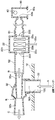
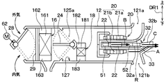
- FIG. 1 is a cross-sectional view showing the main configuration of a vehicle air conditioner 10 according to the present embodiment.
- FIG. 1 schematically shows an inside air temperature sensor 40, an aspirator 32 for generating an air flow of the passenger compartment air around the inside air temperature sensor 40, and the like.
- the up and down arrows DR ⁇ b> 1 indicate directions when the vehicle air conditioner 10 is mounted on a vehicle. That is, the double-ended arrow DR1 in FIG.
- the air conditioner 10 for vehicles is arrange
- the vehicle air conditioner 10 includes an air conditioning case 12, an inside / outside air switching door 28, an evaporator 16, a heater core 18, an air mix door 24, a dustproof filter 29, a blower 20, and the like.
- the vehicle air conditioner 10 of the present embodiment is configured with a suction-type layout in which the blower 20 is disposed on the downstream side of the air flow with respect to the evaporator 16 and the heater core 18.
- the air conditioning case 12 is a case constituting an air passage through which air flows, and is made of a resin member. In FIG. 1, the main part of the entire air conditioning case 12 is illustrated.
- the air conditioning case 12 is provided with an inside / outside air switching door 28 that changes the air volume ratio between the outside air that is air outside the passenger compartment and the inside air volume that is air inside the passenger compartment.
- the inside / outside air switching door 28 is driven by an electric actuator 62, and the operation of the electric actuator 62 is controlled by a control signal output from an air conditioning control device (not shown).
- outside air that is air outside the vehicle interior or inside air that is air inside the vehicle interior is introduced by the blower 20. Further, outside air or inside air introduced into the air conditioning case 12 flows into the evaporator 16 through the dust filter 29.
- the evaporator 16 is a cooling heat exchanger or a cooler that cools the air flowing in the air conditioning case 12.
- the evaporator 16 is accommodated in the air conditioning case 12 and is arranged so that outside air or inside air introduced into the air conditioning case 12 flows in.
- the evaporator 16 constitutes a known refrigeration cycle apparatus that circulates refrigerant together with a compressor, a condenser, and an expansion valve (not shown). The evaporator 16 cools the air passing through the evaporator 16 by evaporation of the refrigerant.
- the structure of the evaporator 16 is the same as a well-known evaporator generally used for a vehicle air conditioner.
- the evaporator 16 includes a core part 161 that performs heat exchange and cooling of air flowing in the air conditioning case 12, and a first header tank part 162 and a core part 161 provided at the upper end of the core part 161. It is comprised from the 2nd header tank part 163 provided in the lower end.
- the core part 161, the 1st header tank part 162, and the 2nd header tank part 163 are comprised with metal materials with high heat conductivity, such as aluminum.
- the core portion 161 of the evaporator 16 includes a plurality of refrigerant tubes each having a flat cross-sectional shape that communicates with the header tank portions 162 and 163, and a plurality of corrugated fins that are provided between the refrigerant tubes and formed into a wave shape. It is composed of The core portion 161 has a structure in which refrigerant tubes and corrugated fins are alternately stacked in the vehicle longitudinal direction.
- the core part 161 is divided into a plurality of fine air passages by the refrigerant tube and the corrugated fin, in the core part 161, air flows exclusively in the thickness direction of the core part 161.
- the heater core 18 is a heat exchanger for heating, that is, a heater that heats the air that has flowed out of the evaporator 16 with engine cooling water that is hot water.
- the heater core 18 is disposed downstream of the evaporator 16 in the air flow in the air conditioning case 12.
- the evaporator 16 and the heater core 18 are air conditioners that adjust the temperature of the air flowing through the air passage of the air conditioning case.
- the structure of the heater core 18 is the same as a known heat exchanger for heating generally used in a vehicle air conditioner.
- the heater core 18 includes a core portion 181 and a first header tank portion 182 and a second header tank portion 183 provided at both ends of the core portion 181.
- the core portion 181 of the heater core 18 is composed of a plurality of hot water tubes each having a flat cross-sectional shape communicating with the header tank portions 182 and 183, and a plurality of corrugated fins provided between the hot water tubes and formed in a wave shape. It is configured.
- the core portion 181 has a structure in which hot water tubes and corrugated fins are alternately stacked in the vehicle longitudinal direction.
- the heater core 18 heat exchange between the high-temperature engine coolant flowing in the hot water tube and the air passing through the core portion 181 is performed, whereby the air is heated. Moreover, since the core part 181 is divided into a plurality of fine air passages by the hot water tube and the corrugated fin, in the core part 181, the air flows exclusively in the thickness direction of the core part 181.
- the heater core 18 is spaced from the evaporator 16, and an air outflow surface through which the air that has passed through the core portion 181 flows out and an air outflow surface through which the air that has passed through the core portion 161 of the evaporator 16 outflows. It arrange
- an air mix door 24 is provided between the heater core 18 and the evaporator 16.
- the air mix door 24 is a rotary door mechanism and is rotated by an electric actuator (not shown).
- the air mix door 24 adjusts the air volume ratio between the air volume passing through the heater core 18 and the air volume passing through the bypass passage 125a that bypasses the upper side of the heater core 18 in the air conditioning case 12 according to the rotation position.
- a blower 20 that generates an air flow in the air passage of the air conditioning case 12 is disposed on the downstream side of the air flow of the heater core 18.
- the blower 20 includes a blower fan 21 and an electric motor 22.
- the electric motor 22 has a rotating shaft 22a, and the blower fan 21 is fixed to the distal end side of the rotating shaft 22a.
- the air conditioning case 12 is formed with a fan storage portion 124 that stores the blower fan 21, and the blower fan 21 is stored in the fan storage portion 124. Further, the electric motor 22 is disposed outside the air conditioning case 12.
- a through hole 128 that penetrates the bottom surface 127 is formed in the bottom surface 127 of the air conditioning case 12.
- the rotary shaft 22 a is inserted into the through hole 128, and the electric motor 22 is fixed to the outside of the air conditioning case 12.
- the blower fan 21 is fixed to the front end side of the rotating shaft 22a of the electric motor 22 in the fan housing 124.
- the electric motor 22 is for rotationally driving the blower fan 21, and its operation is controlled by a control signal output from an air conditioning control device (not shown).
- the blower fan 21 is a centrifugal multiblade fan, and has a plurality of blades (not shown) arranged in a ring around the rotation shaft 22 a of the electric motor 22, and rotates around the rotation shaft 22 a of the electric motor 22.
- the blower fan 21 blows out the air sucked from the distal end direction of the rotating shaft 22a of the electric motor 22 toward the inner diameter side toward the outer diameter side.
- the tip direction of the rotating shaft 22a of the electric motor 22 is the upper side in FIG.
- the fan housing portion 124 of the air conditioning case 12 is formed with a suction port 120 through which the blower fan 21 sucks air, and an opening 121 and an opening 122 through which air blown from the blower fan 21 is discharged.
- the suction port 120 is formed in the tip direction of the rotating shaft 22 a of the electric motor 22.
- the tip direction of the rotating shaft 22a of the electric motor 22 is the upward direction in FIG.
- the opening part 121 and the opening part 122 are formed in the surface of the radial direction outer side of the ventilation fan 21 in the fan accommodating part 124.
- FIG. Specifically, the opening 121 is formed on one side surface of the fan storage portion 124.
- the opening 122 is formed on one side surface of the fan storage portion 124 in which the opening 121 is formed and on a corner portion of the bottom surface 127 of the air conditioning case 12. Note that one side surface of the fan storage portion 124 is the right side surface in FIG.
- a drain hole 127 a for draining the condensed water generated in the evaporator 16 is formed on the bottom surface 127 of the air conditioning case 12. Condensed water is discharged out of the air conditioning case 12 through the drain hole 127a.
- the blower fan 21 blows air sucked from the suction port 120 formed in the distal direction of the rotating shaft 22 a of the electric motor 22 to the opening 121 and the opening 122 formed in the air conditioning case 12.
- the tip direction of the rotating shaft 22a of the electric motor 22 is the upper side in FIG.
- the opening 121 is connected to a face air outlet (not shown), a foot air outlet (not shown), and a defroster air outlet (not shown) provided in the vehicle interior via a duct (not shown) that forms an air passage.
- the opening 122 is connected to the aspirator 32 via the duct 33.
- An ordinary vehicle is equipped with an aspirator 32 that sucks air in the passenger compartment.
- the aspirator 32 is connected to the inside air temperature sensor 40 via a hose 52, a housing 221 of the motor 22, and a bellows-like hose 51.
- a negative pressure that is, a reduced pressure state by the venturi effect using the air blown by the blower 20, and to suck the vehicle interior air using the negative pressure.
- the vehicle air conditioner provided in the vehicle determines the blowing temperature of the conditioned air blown into the vehicle interior using the temperature of the vehicle interior air detected by the inside air temperature sensor 40, and sends the conditioned air of this blowing temperature into the vehicle interior. Air-conditioning control is performed to blow out.
- the vehicle air conditioner in the present embodiment is configured to cool the electric motor 22 of the blower 20 using the air in the passenger compartment that is sucked into the aspirator 32 from around the inside air temperature sensor 40.
- the inside air temperature sensor 40 and the aspirator 32 are directly connected by a bellows-shaped hose.
- the electric motor 22 is interposed between the inside air temperature sensor 40 and the aspirator 32.
- a housing 221 is disposed.
- FIG. 2 is a cross-sectional view showing the main components of the inside air temperature sensor 40, the electric motor 22, and the aspirator 32.
- the inside air temperature sensor 40 is disposed in a sensor storage unit 50 provided on the instrument panel in the passenger compartment.
- the sensor housing 50 is formed with an opening 50a that opens into the vehicle compartment and a suction port 50b for supplying air inside the vehicle compartment to the aspirator 32.
- a bellows-like hose 51 that introduces air in the passenger compartment to the aspirator 32 is connected to the suction port 50b. Since the inside air temperature sensor 40 and the aspirator 32 are arranged at positions separated from each other, the inside air temperature sensor 40 and the aspirator 32 are connected via a bellows-like hose 51.
- the electric motor 22 and the aspirator 32 of the blower 20 are provided on the outer peripheral surface of the air conditioning case 12 disposed in the instrument panel of the vehicle.
- the electric motor 22 is disposed at a position where the vehicle interior air passing through the hose 51 hits.
- the electric motor 22 has a resin casing 221 that houses a rotor 22b attached to a rotating shaft 22a of the electric motor 22, a stator 22c that interacts with the rotor 22b and generates a rotational moment, and the like.
- the housing 221 has an opening 222 for introducing air around the inside air temperature sensor 40 and an opening 223 for discharging the air introduced into the housing 221.
- An opening 222 formed in the housing 221 of the electric motor 22 is connected to a suction port 50 b formed in the sensor storage unit 50 in which the inside air temperature sensor 40 is disposed via a bellows-like hose 51.
- the aspirator 32 has a cylindrical resin nozzle 32a and a resin venturi 32b which is cylindrical and L-shaped.
- the nozzle 32a and the venturi 32b are joined by adhesion or the like.
- the duct 33 connected to the opening 122 formed in the air conditioning case 12 is hermetically inserted and fixed to one end side of the venturi 32b, and the aspirator 32 is integrally attached to the air conditioning case 12.
- the air in the air conditioning case 12 is introduced into the venturi 32b via the duct 33.
- the venturi 32b has a throttle portion R for restricting the flow of air introduced into the venturi 32b.
- the other end side of the venturi 32b is opened toward the opening space in the instrument panel of the vehicle.
- the throttle portion R is the minimum diameter portion.
- One end of the nozzle 32a is connected to the opening 222 formed in the housing 221 of the electric motor 22 via the hose 52, and the other end of the nozzle 32a opens to the minimum diameter portion R of the venturi 32b.
- the hose 51 and the hose 52 are air introduction members that introduce the air in the passenger compartment into the aspirator 32.
- the aspirator 32 introduces air flowing through the air passage of the air conditioning case 12 as primary air.
- the aspirator 32 draws the air in the vehicle interior as secondary air by the primary air through the hose 51, the housing 221 of the electric motor 22, and the hose 52, and sucks the primary air and secondary air into the instrument panel of the vehicle. It discharges toward the opening space inside.
- the outside air that is the air outside the vehicle compartment or the inside air that is the air inside the vehicle compartment is introduced into the air conditioning case 12 according to the position of the inside / outside air switching door 28.
- the air passes through the dust-proof filter 29 and is then cooled by the evaporator 16 to become cold air.
- the cold air was then divided into cold air passing through the bypass passage 125a that bypasses the upper side of the heater core 18 according to the opening of the air mix door 24, and hot air heated through the heater core 18. Thereafter, the air flows downstream of the heater core 18 and merges.
- the blower 20 sucks the air that has joined together on the downstream side of the air flow of the heater core 18 through the suction port 120 formed in the fan housing portion 124 and blows it out to the outer peripheral side of the diameter. Then, a part of the air blown out by the blower 20 passes through a duct (not shown) that forms an air passage from the opening 121, and passes through a duct (not shown), a foot outlet (not shown), and a defroster outlet (not shown). Blown out. Further, the remaining air blown out by the blower 20 is introduced from the opening 122 through the duct 33 to the venturi 32b of the aspirator 32 as shown by an arrow A in FIG.
- the air passing through the throttle portion R in the venturi 32b is depressurized, and as indicated by the arrow B, air is sucked from the nozzle 32a.
- the air in the passenger compartment around the inside air temperature sensor 40 is introduced into the housing 221 of the electric motor 22 via the hose 51, and the air introduced into the housing 221 passes through the gap inside the housing 221. After passing, it is introduced into the venturi 32b through the hose 52 and the nozzle 32a.
- the air introduced into the venturi 32b through the nozzle 32a is discharged toward the opening space in the instrument panel of the vehicle as indicated by an arrow C.
- the vehicle air conditioner 10 includes the air conditioning case 12 that forms an air passage through which air flows, the blower 20 that has the blower fan 21 that generates an air flow in the air passage, and the air passage. Air conditioners 16 and 18 for adjusting the temperature of the air flowing through the passage are provided.
- the vehicle air conditioner 10 further includes hoses 51 and 52 for introducing the air in the passenger compartment, and air that is disposed outside the case and flows through the air passage as primary air. And an aspirator 32 that sucks air in the vehicle interior as secondary air through 51 and 52. And it is comprised so that the electric motor 22 which drives the ventilation fan 21 with the air flow in the vehicle interior attracted
- the electric motor 22 as a member to be cooled which is mounted on the vehicle, is cooled by the air flow in the passenger compartment passing through the hoses 51 and 52 by being sucked by the aspirator arranged outside the case.
- a to-be-cooled member can be cooled by a simple structure, without enlarging the physique of a case.
- an inside air temperature sensor 40 for detecting the temperature of the inside air in the vehicle interior is arranged in the vehicle interior, and the aspirator 32 sucks air in the vehicle interior around the inside air temperature sensor 40 via the hoses 51 and 52. It is configured. According to such a configuration, since the existing aspirator 32 that sucks the ambient air around the ambient temperature sensor 40 can be used, the configuration can be simplified and the cost can be reduced.
- the air conditioning case 12 has an opening 122 for introducing air flowing through the air passage in the air conditioning case 12 to the aspirator 32 on the downstream side of the air flow from the blower 20. According to such a configuration, the air passage in the air conditioning case 12 can be introduced into the aspirator 32 using the opening 122 disposed on the downstream side of the air flow from the blower 20.
- the air in the air conditioning case 12 is supplied into the venturi 32b through the duct 33.
- the air supplied from the air conditioning case 12 through the duct 33 is directly applied to the electric motor 22 of the blower fan 21 to be cooled.
- the duct 33 is disposed on the downstream side of the air flow of the evaporator 16, and the relative humidity of the air supplied through the duct 33 is high. Become. For this reason, in the vehicle air conditioner 10, when the air supplied through the duct 33 is directly applied to the electric motor 22 of the blower fan 21, condensation occurs in the electric motor 22.
- the vehicle air conditioner 10 uses the aspirator 32 to introduce the air introduced from the air conditioning case 12 through the duct 33, although the blower 20 is disposed on the downstream side of the air flow of the air conditioners 16 and 18. The air in the passenger compartment is sucked in. And this vehicle air conditioner 10 becomes a structure which cools a to-be-cooled object member with the air in this vehicle interior. Therefore, the vehicle air conditioner 10 can cool the member to be cooled without causing condensation on the member to be cooled.
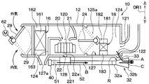
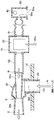
- FIG. 3 is a cross-sectional view showing the main configuration of the vehicle air conditioner 10 of the present embodiment.
- the inside air temperature sensor 40 is omitted in FIG. 3, the inside air temperature sensor 40 is also disposed in the sensor storage portion 50 provided on the instrument panel in the vehicle interior in this embodiment.
- the sensor storage unit 50 that stores the inside air temperature sensor 40 and the electric motor 22 are connected via a bellows-like hose 51.
- the vehicle air conditioner 10 according to the first embodiment includes the blower 20 having one blower fan 21
- the vehicle air conditioner 10 according to the present embodiment includes the blower 21a and 21b. 20 is different.
- the blower 20 of the present embodiment is configured as a double fan that drives two blower fans 21 a and 21 b with one motor 22.
- the blower fan 21 a is disposed on the upper side of the air conditioning case 12, and the blower fan 21 b is disposed on the lower side of the air conditioning case 12.
- the blower fan 21 a is fixed to one end of the rotating shaft of the motor 22, and the blower fan 21 b is fixed to one end of the rotating shaft of the motor 22.
- the blower fan 21a and the blower fan 21b rotate around the rotation shaft of the motor 22, respectively.
- the blower fan 21a sucks air cooled mainly by the evaporator 16 from one end side of the rotation shaft of the motor 22 (upper side in FIG. 3) and blows it out toward the outer circumference.
- the air blown from the blower fan 21a is blown into the vehicle interior via the face outlet and the defroster outlet via the opening 121a provided in the air conditioning case 12.
- the blower fan 21b sucks in air heated mainly by the heater core 18 from the other end side of the rotating shaft of the motor 22 and blows it out in the radial outer peripheral direction.
- the air blown from the blower fan 21b is mainly blown into the vehicle interior via the foot outlet through the opening 121b provided in the air conditioning case 12.
- a part of the air blown out from the blower fan 21 b is introduced into the venturi 32 b of the aspirator 32 through the duct 33.
- the blower 20 when the blower 20 is operated, the outside air that is the air outside the vehicle interior or the inside air that is the air inside the vehicle interior is introduced into the air conditioning case 12 according to the position of the inside / outside air switching door 28.
- the air passes through the dust-proof filter 29 and is then cooled by the evaporator 16 to become cold air.
- This cold air is then divided into cold air that passes through the bypass passage 125a that bypasses the upper side of the heater core 18 according to the opening of the air mix door 24, and hot air that is heated through the heater core 18.
- the cool air that has passed through the bypass passage 125a is mainly sucked into the blower fan 21a, and then the vehicle interior through the opening 121a provided in the air conditioning case 12 by the blower fan 21a through the face blower outlet and the defroster blower outlet. It is blown to.
- a part of the warm air heated through the heater core 18 is mainly sucked into the blower fan 21b and then passed through the foot outlet through the opening 121b provided in the air conditioning case 12 by the blower fan 21b. The air is blown into the passenger compartment.
- the remainder of the warm air heated through the heater core 18 is introduced into the venturi 32b of the aspirator 32 through the duct 33, and the air in the vehicle compartment is sucked from the nozzle 32a as indicated by the arrow B by the venturi effect.
- the air in the passenger compartment around the inside air temperature sensor 40 is introduced into the casing 221 of the electric motor 22 via the hose 51, and the air introduced into the casing 221 passes through the gap inside the casing 221. After passing, it is introduced into the venturi 32b through the hose 52 and the nozzle 32a.
- a space is provided on the upstream side of the air flow of the blower 20 where the cold air that has passed through the bypass passage 125a and hot air that has been heated through the heater core 18 are mixed.
- the present disclosure discloses an air conditioning unit in which the inside of the air conditioning case 12 is divided into an upper space and a lower space, and an inside / outside air two-layer flow mode in which outside air flows in the upper space and inside air flows in the lower space can be set. Can also be applied.
- a part of the air blown out from the blower fan 21b is configured to be introduced into the venturi 32b of the aspirator 32 through the duct 33.
- a part of the air blown out from the blower fan 21 a may be configured to be introduced into the venturi 32 b of the aspirator 32 through the duct 33.
- FIG. 4 is a cross-sectional view showing the main configuration of the vehicle air conditioner 10 of the present embodiment.
- the vehicle air conditioner 10 according to the first embodiment is configured with a suction layout in which the blower 20 is disposed on the downstream side of the air flow with respect to the evaporator 16 and the heater core 18.
- the vehicle air conditioner 10 of the present embodiment is configured with a push-in layout in which the blower 20 is disposed on the upstream side of the air flow with respect to the evaporator 16 and the heater core 18.
- the air conditioning case 12 is formed with an opening 122 for discharging the air blown from the blower fan 21, and the opening 122 is connected to the aspirator 32 via the duct 33.
- the blower fan 21 sucks the air introduced into the air conditioning case 12 from the distal end direction of the rotating shaft 22a of the electric motor 22 toward the inner diameter side and blows it toward the outer diameter side. Air blown from the blower fan 21 is mainly introduced into the evaporator 16. Further, a part of the air blown from the blower fan 21 is introduced into the venturi 32b of the aspirator 32 through the duct 33 through the opening 122, and due to the venturi effect, as shown by the arrow B, from the nozzle 32a into the vehicle interior. Air is aspirated.
- the air in the passenger compartment around the inside air temperature sensor 40 is introduced into the casing 221 of the electric motor 22 via the hose 51, and the air introduced into the casing 221 passes through the gap inside the casing 221. After passing, it is introduced into the venturi 32b through the hose 52 and the nozzle 32a.
- the tip direction of the rotating shaft 22a of the electric motor 22 is the upper side in FIG.
- the air introduced from the blower fan 21 to the evaporator 16 is cooled by the evaporator 16 and becomes cold air. This cold air is then divided into cold air that passes through the bypass passage 125a that bypasses the upper side of the heater core 18 according to the opening of the air mix door 24, and hot air that is heated through the heater core 18.
- the cool air that has passed through the bypass passage 125a is mainly sucked into the blower fan 21a, and then the vehicle interior through the opening 121a provided in the air conditioning case 12 by the blower fan 21a through the face blower outlet and the defroster blower outlet. It is blown to.
- FIG. 5 is a cross-sectional view showing the main configuration of the vehicle air conditioner 10 of the present embodiment.
- the blower 20 is disposed on the bottom surface 127 of the air conditioning case 12.
- the blower 20 is upward in the air conditioning case 12. It is different in that it is arranged on the surface. In this way, the present disclosure can be applied to the vehicle air conditioner 10 in which the blower 20 is disposed on the upper surface in the air conditioning case 12.
- FIG. 6 is a cross-sectional view showing a main configuration of the vehicle air conditioner 10 of the present embodiment.
- the vehicle air conditioner 10 of the first embodiment is configured such that the blower 20 is disposed on the downstream side of the air flow with respect to the evaporator 16 and the heater core 18.
- the blower 20 is disposed on the downstream side of the air flow with respect to the evaporator 16 and on the upstream side of the air flow with respect to the heater core 18. It is configured.
- the air conditioning case 12 is formed with an opening 122 for discharging the air blown from the blower fan 21, and the opening 122 is connected to the aspirator 32 via the duct 33.
- the air passes through the dust-proof filter 29 and is then cooled by the evaporator 16 to become cold air.
- the blower fan 21 sucks air introduced into the air conditioning case 12 and cooled by the evaporator 16 from the distal end direction of the rotating shaft 22a of the electric motor 22 toward the inner diameter side and blows it to the outer diameter side.
- the cool air blown from the blower fan 21 then passes through the bypass passage 125a that bypasses the upper side of the heater core 18 to the air mix door 24 according to the opening degree, and the warm air heated through the heater core 18 is heated. Then, the air flows downstream of the heater core 18 and merges.
- the tip direction of the rotating shaft 22a of the electric motor 22 is the upper side in FIG.
- the air whose temperature is adjusted by being blown from the blower fan 21 mainly passes through a duct (not shown) that forms an air passage from the opening 121, and from a face outlet, not shown, and a defroster outlet (not shown). It is blown out into the passenger compartment. Further, the remaining air blown out by the blower 20 is introduced into the venturi 32b of the aspirator 32 from the opening 122 through the duct 33 as shown by an arrow A shown in FIG. At this time, the air passing through the throttle portion R in the venturi 32b is depressurized, and as indicated by the arrow B, air is sucked from the nozzle 32a.
- the air in the passenger compartment around the inside air temperature sensor 40 is introduced into the housing 221 of the electric motor 22 via the hose 51, and the air introduced into the housing 221 is a gap inside the housing 221. Is passed through the hose 52 and the nozzle 32a and introduced into the venturi 32b.
- the air introduced into the venturi 32b through the nozzle 32a is discharged toward the opening space in the instrument panel of the vehicle as indicated by an arrow C.
- the present disclosure is not limited to the above embodiment, and can be implemented in various forms based on the gist of the present disclosure.
- the opening 122 of the air conditioning case 12 and the air conditioning air inlet 32c of the aspirator 32 are connected by the duct 33.
- the air conditioning air inlet 32c of the aspirator 32 is connected to the air conditioning case 12. You may make it connect directly to the opening part 122 of this.
- Each of the above embodiments shows a configuration in which the electric motor 22 is cooled by introducing the air in the vehicle compartment sucked by the aspirator 32 into the housing 221 of the electric motor 22 as a member to be cooled. It was.
- a cooling case 70 that houses an electric motor 22 as a member to be cooled is provided, and air in the vehicle compartment that is sucked by the aspirator 32 is introduced into the cooling case 70. You may make it cool so that a to-be-cooled member may be comprised. With such a configuration, the member to be cooled can be cooled without changing the shape of the member to be cooled.
- the configuration in which the electric motor 22 that drives the blower fan 21 is cooled by the air flow in the vehicle compartment sucked by the aspirator 32 is used as a member to be cooled.
- the configuration is not limited to the electric motor 22, and for example, shows a configuration in which at least one electric device included in a navigation device, a head-up display device, and a meter mounted on a vehicle is cooled as a member to be cooled. Also good.
- the inside air temperature sensor 40 that detects the temperature of the inside air in the inside of the vehicle interior is arranged in the vehicle interior, and the aspirator 32 removes the inside air around the inside air temperature sensor 40 via the hoses 51 and 52. Configured to aspirate.
- the inside air temperature sensor 40 that detects the temperature of the inside air in the vehicle compartment is not necessarily arranged in the vehicle compartment.
- the blower fan 21 is arranged on the bottom surface 127 side of the air conditioning case 12, and in the fourth embodiment, the blower fan 21 is arranged on the upper surface of the air conditioning case 12. .
- the arrangement of the blower fan 21 and the electric motor 22 is not limited to that shown in the above embodiment.
- the blower fan 21 that is a centrifugal multiblade fan is used.
- the blower fan 21 is not limited to the centrifugal multiblade fan.
- a sirocco fan may be used as the blower fan 21. .
- the inside / outside air switching door 28 is configured to be driven by the electric actuator 62.
- the inside / outside air switching door 28 may be configured to be driven by a passenger's manual operation.
Landscapes
- Physics & Mathematics (AREA)
- Thermal Sciences (AREA)
- Engineering & Computer Science (AREA)
- Mechanical Engineering (AREA)
- Air-Conditioning For Vehicles (AREA)
Abstract
Description
本開示の第1実施形態に係る車両用空調装置10について図1~図2を参照して説明する。図1は、本実施形態の車両用空調装置10の主要な構成を示す断面図である。なお、図1には、内気温センサ40、この内気温センサ40の周囲に車室内空気の空気流れを発生させるアスピレータ32等が模式的に示されている。図1において上下の各矢印DR1は、車両用空調装置10が車両に搭載された車両搭載状態での向きを示す。すなわち、図1の両端矢印DR1は車両上下を示している。
本開示の第2実施形態に係る車両用空調装置10について図3を参照して説明する。図3は、本実施形態の車両用空調装置10の主要な構成を示す断面図である。なお、図3において、内気温センサ40を省略してあるが、本実施形態においても、内気温センサ40は、車室内におけるインストルメントパネルに設けられたセンサ収納部50内に配置されている。また、第1実施形態と同様に、内気温センサ40を収納するセンサ収納部50と電動モータ22の間は、蛇腹状のホース51を介して接続されている。
本開示の第3実施形態に係る車両用空調装置10について図4を参照して説明する。図4は、本実施形態の車両用空調装置10の主要な構成を示す断面図である。
本開示の第4実施形態に係る車両用空調装置10について図5を参照して説明する。図5は、本実施形態の車両用空調装置10の主要な構成を示す断面図である。
本開示の第5実施形態に係る車両用空調装置10について図6を参照して説明する。図6は、本実施形態の車両用空調装置10の主要な構成を示す断面図である。
本開示は上記実施形態に限定されるものではなく、本開示の趣旨に基づいて種々なる形態で実施することができる。
Claims (9)
- 車両に搭載される車両用空調装置であって、
空気が流れる空気通路を構成するケース(12)と、
前記空気通路に空気流れを生じさせる送風ファン(21、21a、21b)を有する送風機(20)と、
前記空気通路に配置され、前記空気通路を流れる空気の温度を調整する空調機器(16、18)と、
車室内の空気を導入する空気導入部材(51、52)と、
前記ケースの外部に配置され、前記空気通路を流れる空気を1次空気として導入し、前記1次空気の流れによって前記空気導入部材を介して前記車室内の空気を2次空気として吸引するアスピレータ(32)と、を備え、
前記アスピレータに吸引されて前記空気導入部材を通る前記車室内の空気流れにより、車両に搭載された被冷却部材(22)が、冷却される車両用空調装置。 - 前記車室内には、前記車室内の内気の温度を検出する内気温センサ(40)が配置され、
前記アスピレータは、前記空気導入部材を介して前記内気温センサの周囲の前記車室内の空気を吸引する請求項1に記載の車両用空調装置。 - 前記被冷却部材は、前記空気導入部材を通る前記車室内の空気が当たる位置に配置されている請求項1または2に記載の車両用空調装置。
- 前記被冷却部材を収納する冷却ケース(70)を備え、
前記空気導入部材を通る前記車室内の空気が前記冷却ケースに導入される請求項1ないし3のいずれか1つに記載の車両用空調装置。 - 前記被冷却部材は、前記ケースの外部に配置されて前記送風ファンを駆動する電動モータ(22)である請求項1ないし4のいずれか1つに記載の車両用空調装置。
- 前記被冷却部材は、前記車両に搭載されたナビゲーション装置、ヘッドアップディスプレイ装置およびメータに含まれる少なくとも1つの電気機器である請求項1ないし4のいずれか1つに記載の車両用空調装置。
- 前記ケースは、前記送風機より空気流れ下流側に前記ケース内の前記空気通路を流れる空気を前記アスピレータへ導入する開口部(122)を有する請求項1ないし6のいずれか1つに記載の車両用空調装置。
- 前記送風機は、前記空調機器の空気流れ下流側に配置されている請求項1ないし7のいずれか1つに記載の車両用空調装置。
- 前記空調機器は、前記ケース内を流れる空気を冷却する冷却器(16)と、該冷却器から流出した空気を加熱する加熱器(18)であり、
前記送風機は、前記冷却器の空気流れ下流側であって前記加熱器の空気流れ上流側に配置されている請求項1ないし7のいずれか1つに記載の車両用空調装置。
Priority Applications (4)
| Application Number | Priority Date | Filing Date | Title |
|---|---|---|---|
| DE112016001898.3T DE112016001898T5 (de) | 2015-04-24 | 2016-03-08 | Fahrzeugklimatisierungsvorrichtung |
| CN201680023170.9A CN107531125B (zh) | 2015-04-24 | 2016-03-08 | 车辆用空调装置 |
| US15/567,413 US10549598B2 (en) | 2015-04-24 | 2016-03-08 | Vehicle air-conditioning apparatus |
| JP2017514007A JP6384599B2 (ja) | 2015-04-24 | 2016-03-08 | 車両用空調装置 |
Applications Claiming Priority (2)
| Application Number | Priority Date | Filing Date | Title |
|---|---|---|---|
| JP2015089528 | 2015-04-24 | ||
| JP2015-089528 | 2015-04-24 |
Publications (1)
| Publication Number | Publication Date |
|---|---|
| WO2016170862A1 true WO2016170862A1 (ja) | 2016-10-27 |
Family
ID=57144582
Family Applications (1)
| Application Number | Title | Priority Date | Filing Date |
|---|---|---|---|
| PCT/JP2016/057235 Ceased WO2016170862A1 (ja) | 2015-04-24 | 2016-03-08 | 車両用空調装置 |
Country Status (5)
| Country | Link |
|---|---|
| US (1) | US10549598B2 (ja) |
| JP (1) | JP6384599B2 (ja) |
| CN (1) | CN107531125B (ja) |
| DE (1) | DE112016001898T5 (ja) |
| WO (1) | WO2016170862A1 (ja) |
Cited By (1)
| Publication number | Priority date | Publication date | Assignee | Title |
|---|---|---|---|---|
| WO2020137272A1 (ja) * | 2018-12-27 | 2020-07-02 | 株式会社デンソー | 粉塵検出装置 |
Families Citing this family (10)
| Publication number | Priority date | Publication date | Assignee | Title |
|---|---|---|---|---|
| JP6384599B2 (ja) * | 2015-04-24 | 2018-09-05 | 株式会社デンソー | 車両用空調装置 |
| JP7234619B2 (ja) * | 2018-12-20 | 2023-03-08 | 株式会社デンソー | 車両用空調装置 |
| JP7183804B2 (ja) * | 2019-01-11 | 2022-12-06 | 株式会社デンソー | 車両用空調装置 |
| JP7077989B2 (ja) * | 2019-02-20 | 2022-05-31 | 株式会社デンソー | 車両用空調ユニット |
| AU2020390313B2 (en) * | 2019-11-25 | 2025-12-11 | Husqvarna Ab | A hand-held electrically powered work tool |
| WO2021137296A1 (ja) * | 2020-01-01 | 2021-07-08 | 株式会社ヴァレオジャパン | 車両用空調装置 |
| JP7618399B2 (ja) * | 2020-06-30 | 2025-01-21 | 株式会社ヨコオ | 電子機器の温度調整構造 |
| KR20220056920A (ko) * | 2020-10-28 | 2022-05-09 | 현대자동차주식회사 | 전기차량용 공조장치 및 이를 이용한 전기차량용 공조시스템 |
| US12023981B2 (en) * | 2022-07-22 | 2024-07-02 | Hanon Systems | Quad zone booster intake LPM cooling assembly |
| US20240300273A1 (en) * | 2023-03-10 | 2024-09-12 | Apple Inc. | Spring System |
Citations (5)
| Publication number | Priority date | Publication date | Assignee | Title |
|---|---|---|---|---|
| JPH041012U (ja) * | 1990-04-09 | 1992-01-07 | ||
| JPH08276722A (ja) * | 1995-04-06 | 1996-10-22 | Zexel Corp | 空調ユニット |
| JPH0920127A (ja) * | 1995-07-04 | 1997-01-21 | Nippon Climate Syst:Kk | 車両用空調装置 |
| JPH10157438A (ja) * | 1996-12-03 | 1998-06-16 | Calsonic Corp | 車両用空気調和装置 |
| JP2008189247A (ja) * | 2007-02-07 | 2008-08-21 | Calsonic Kansei Corp | 車両用空調装置 |
Family Cites Families (31)
| Publication number | Priority date | Publication date | Assignee | Title |
|---|---|---|---|---|
| USRE21761E (en) * | 1932-08-12 | 1941-04-08 | ashley | |
| US2592712A (en) * | 1944-04-10 | 1952-04-15 | Robert T Collier | Portable refrigerator |
| US2780077A (en) * | 1954-07-21 | 1957-02-05 | Gen Motors Corp | Vehicle refrigerating apparatus |
| US3320761A (en) * | 1965-05-12 | 1967-05-23 | Gen Electric | Single evaporator, single fan combination refrigerator |
| US3893307A (en) * | 1974-05-03 | 1975-07-08 | Gen Motors Corp | Refrigerator freezer with frost eliminator |
| JPS57148554A (en) * | 1981-03-06 | 1982-09-13 | Hitachi Ltd | Cooler for blower driving motor |
| DE3463016D1 (en) * | 1984-03-19 | 1987-05-14 | Siemens Ag | Heating or air conditioning apparatus for motor vehicles with automatic control of the interior temperature |
| US4814653A (en) * | 1986-12-30 | 1989-03-21 | Hitachi, Ltd. | Device for air cooling bearing of hermetic dynamic machine |
| US5364025A (en) * | 1992-04-27 | 1994-11-15 | Ford Motor Company | Combination motor cooler and air aspirator for climate control system |
| SE508811C2 (sv) * | 1993-08-04 | 1998-11-09 | Electrolux Sarl | Fordon med ett absorptionskylskåp |
| JP3222375B2 (ja) * | 1995-03-20 | 2001-10-29 | トヨタ自動車株式会社 | 車両用空気調和装置 |
| JPH09123732A (ja) * | 1995-11-01 | 1997-05-13 | Zexel Corp | 自動車用空気調和装置 |
| JP3293573B2 (ja) * | 1998-11-18 | 2002-06-17 | 株式会社デンソー | 車両用空調装置 |
| US5955803A (en) * | 1998-12-07 | 1999-09-21 | Ford Motor Company | Device for cooling a motor in a climate control system |
| DE10002231A1 (de) * | 2000-01-20 | 2001-08-02 | Bosch Gmbh Robert | Gebläsemotor |
| US6584795B1 (en) * | 2002-04-30 | 2003-07-01 | Deere & Company | Condensate drain for an air conditioning system |
| KR101115130B1 (ko) * | 2004-12-21 | 2012-02-24 | 한라공조주식회사 | 차량용 이층류 공조장치 |
| US20080115518A1 (en) * | 2005-08-03 | 2008-05-22 | Calsonic Kansei Corporation | Vehicular Air Conditioner |
| US8033899B2 (en) * | 2005-08-31 | 2011-10-11 | Kubota Corporation | Cabin for a work vehicle |
| JP2007168642A (ja) * | 2005-12-22 | 2007-07-05 | Denso Corp | 車両用空調装置 |
| JP2007314056A (ja) * | 2006-05-26 | 2007-12-06 | Denso Corp | 車両用空調装置 |
| DE102008033439A1 (de) * | 2007-07-20 | 2009-01-29 | Denso Corporation, Kariya | Fahrzeugklimaanlage und Verfahren zur Steuerung der Fahrzeugklimaanlage |
| JP4396738B2 (ja) | 2007-07-23 | 2010-01-13 | 株式会社デンソー | 空調装置 |
| JP4488075B2 (ja) * | 2008-02-15 | 2010-06-23 | 株式会社デンソー | 電動送風機 |
| KR101302262B1 (ko) * | 2011-03-30 | 2013-09-02 | 가부시끼 가이샤 구보다 | 작업차 |
| JP2013018351A (ja) * | 2011-07-11 | 2013-01-31 | Suzuki Motor Corp | 車両用空調装置 |
| US8998587B2 (en) * | 2011-12-16 | 2015-04-07 | Denso International America, Inc. | Blower motor cooling tube noise suppressor for ticking/chirping |
| JP6134535B2 (ja) * | 2013-02-26 | 2017-05-24 | 株式会社ケーヒン | 車両用空気調和装置 |
| US20150165866A1 (en) * | 2013-12-18 | 2015-06-18 | Hyundai Motor Company | Aspirator in-car sensor module for vehicle, installation structure of in-car sensor module and vehicle having the installation structure |
| JP6384599B2 (ja) * | 2015-04-24 | 2018-09-05 | 株式会社デンソー | 車両用空調装置 |
| US20190126724A1 (en) * | 2017-10-26 | 2019-05-02 | Denso International America, Inc. | Under Vehicle Mounted Cooling Assemblies Including Horizontally Mounted Condensers With Vertical Air Flow |
-
2016
- 2016-03-08 JP JP2017514007A patent/JP6384599B2/ja not_active Expired - Fee Related
- 2016-03-08 WO PCT/JP2016/057235 patent/WO2016170862A1/ja not_active Ceased
- 2016-03-08 US US15/567,413 patent/US10549598B2/en not_active Expired - Fee Related
- 2016-03-08 CN CN201680023170.9A patent/CN107531125B/zh not_active Expired - Fee Related
- 2016-03-08 DE DE112016001898.3T patent/DE112016001898T5/de not_active Ceased
Patent Citations (5)
| Publication number | Priority date | Publication date | Assignee | Title |
|---|---|---|---|---|
| JPH041012U (ja) * | 1990-04-09 | 1992-01-07 | ||
| JPH08276722A (ja) * | 1995-04-06 | 1996-10-22 | Zexel Corp | 空調ユニット |
| JPH0920127A (ja) * | 1995-07-04 | 1997-01-21 | Nippon Climate Syst:Kk | 車両用空調装置 |
| JPH10157438A (ja) * | 1996-12-03 | 1998-06-16 | Calsonic Corp | 車両用空気調和装置 |
| JP2008189247A (ja) * | 2007-02-07 | 2008-08-21 | Calsonic Kansei Corp | 車両用空調装置 |
Cited By (3)
| Publication number | Priority date | Publication date | Assignee | Title |
|---|---|---|---|---|
| WO2020137272A1 (ja) * | 2018-12-27 | 2020-07-02 | 株式会社デンソー | 粉塵検出装置 |
| JP2020104693A (ja) * | 2018-12-27 | 2020-07-09 | 株式会社デンソー | 粉塵検出装置 |
| JP7188066B2 (ja) | 2018-12-27 | 2022-12-13 | 株式会社デンソー | 粉塵検出装置 |
Also Published As
| Publication number | Publication date |
|---|---|
| CN107531125B (zh) | 2020-04-07 |
| US20180105013A1 (en) | 2018-04-19 |
| JP6384599B2 (ja) | 2018-09-05 |
| CN107531125A (zh) | 2018-01-02 |
| US10549598B2 (en) | 2020-02-04 |
| DE112016001898T5 (de) | 2018-01-04 |
| JPWO2016170862A1 (ja) | 2017-08-17 |
Similar Documents
| Publication | Publication Date | Title |
|---|---|---|
| JP6384599B2 (ja) | 車両用空調装置 | |
| JP4265355B2 (ja) | 空調装置 | |
| JP6319514B2 (ja) | 送風機 | |
| JP4396738B2 (ja) | 空調装置 | |
| CN109153308B (zh) | 车辆用空调单元 | |
| JP4513835B2 (ja) | 空調装置 | |
| JP6583378B2 (ja) | 車両用空調ユニット | |
| WO2017221460A1 (ja) | 空調装置 | |
| EP2000338A1 (en) | Water discharge structure of vehicle air-conditioning system | |
| JP5954231B2 (ja) | 車両用空調装置 | |
| CN109906160A (zh) | 车辆用空调单元 | |
| JP2009234473A (ja) | ブロワ装置 | |
| WO2019220925A1 (ja) | 車両用空調ユニット | |
| WO2020170754A1 (ja) | 車両用空調ユニット | |
| JP2016196209A (ja) | 車両用空調ユニット | |
| JP2014061790A (ja) | 車両用空調装置 | |
| JP2018001820A (ja) | 送風ユニット | |
| JP2016203823A (ja) | 車両用空調装置 | |
| JP2015128938A (ja) | 車両用送風機および車両用空調装置 | |
| JP5092826B2 (ja) | 空調装置 | |
| JP2016173223A (ja) | 空調装置 | |
| WO2010058666A1 (ja) | 空気調和機 | |
| WO2018025532A1 (ja) | 車両用空調装置 | |
| JP2004196153A (ja) | 車両用空調装置 | |
| JP2009132267A (ja) | 車両用空調装置 |
Legal Events
| Date | Code | Title | Description |
|---|---|---|---|
| 121 | Ep: the epo has been informed by wipo that ep was designated in this application |
Ref document number: 16782884 Country of ref document: EP Kind code of ref document: A1 |
|
| ENP | Entry into the national phase |
Ref document number: 2017514007 Country of ref document: JP Kind code of ref document: A |
|
| WWE | Wipo information: entry into national phase |
Ref document number: 15567413 Country of ref document: US |
|
| WWE | Wipo information: entry into national phase |
Ref document number: 112016001898 Country of ref document: DE |
|
| 122 | Ep: pct application non-entry in european phase |
Ref document number: 16782884 Country of ref document: EP Kind code of ref document: A1 |