WO2016167200A1 - フォークリフト - Google Patents
フォークリフト Download PDFInfo
- Publication number
- WO2016167200A1 WO2016167200A1 PCT/JP2016/061599 JP2016061599W WO2016167200A1 WO 2016167200 A1 WO2016167200 A1 WO 2016167200A1 JP 2016061599 W JP2016061599 W JP 2016061599W WO 2016167200 A1 WO2016167200 A1 WO 2016167200A1
- Authority
- WO
- WIPO (PCT)
- Prior art keywords
- pallet
- fork
- laser sensor
- forklift
- vehicle body
- Prior art date
Links
- 230000007246 mechanism Effects 0.000 claims description 11
- 230000003028 elevating effect Effects 0.000 claims description 7
- 238000000034 method Methods 0.000 description 44
- 230000008569 process Effects 0.000 description 31
- 238000012545 processing Methods 0.000 description 14
- 230000006870 function Effects 0.000 description 9
- 238000001514 detection method Methods 0.000 description 6
- 210000000078 claw Anatomy 0.000 description 5
- 230000008859 change Effects 0.000 description 3
- 238000005259 measurement Methods 0.000 description 3
- 238000013519 translation Methods 0.000 description 3
- 238000004364 calculation method Methods 0.000 description 2
- 238000000605 extraction Methods 0.000 description 2
- NJPPVKZQTLUDBO-UHFFFAOYSA-N novaluron Chemical compound C1=C(Cl)C(OC(F)(F)C(OC(F)(F)F)F)=CC=C1NC(=O)NC(=O)C1=C(F)C=CC=C1F NJPPVKZQTLUDBO-UHFFFAOYSA-N 0.000 description 2
- 238000013459 approach Methods 0.000 description 1
- 238000006243 chemical reaction Methods 0.000 description 1
- 238000007796 conventional method Methods 0.000 description 1
- 238000010586 diagram Methods 0.000 description 1
- 239000000284 extract Substances 0.000 description 1
- 238000012986 modification Methods 0.000 description 1
- 230000004048 modification Effects 0.000 description 1
- 230000003287 optical effect Effects 0.000 description 1
- 230000002093 peripheral effect Effects 0.000 description 1
- 230000032258 transport Effects 0.000 description 1
Images


Classifications
-
- B—PERFORMING OPERATIONS; TRANSPORTING
- B66—HOISTING; LIFTING; HAULING
- B66F—HOISTING, LIFTING, HAULING OR PUSHING, NOT OTHERWISE PROVIDED FOR, e.g. DEVICES WHICH APPLY A LIFTING OR PUSHING FORCE DIRECTLY TO THE SURFACE OF A LOAD
- B66F9/00—Devices for lifting or lowering bulky or heavy goods for loading or unloading purposes
- B66F9/06—Devices for lifting or lowering bulky or heavy goods for loading or unloading purposes movable, with their loads, on wheels or the like, e.g. fork-lift trucks
- B66F9/075—Constructional features or details
- B66F9/0755—Position control; Position detectors
-
- B—PERFORMING OPERATIONS; TRANSPORTING
- B66—HOISTING; LIFTING; HAULING
- B66F—HOISTING, LIFTING, HAULING OR PUSHING, NOT OTHERWISE PROVIDED FOR, e.g. DEVICES WHICH APPLY A LIFTING OR PUSHING FORCE DIRECTLY TO THE SURFACE OF A LOAD
- B66F9/00—Devices for lifting or lowering bulky or heavy goods for loading or unloading purposes
- B66F9/06—Devices for lifting or lowering bulky or heavy goods for loading or unloading purposes movable, with their loads, on wheels or the like, e.g. fork-lift trucks
- B66F9/063—Automatically guided
-
- B—PERFORMING OPERATIONS; TRANSPORTING
- B66—HOISTING; LIFTING; HAULING
- B66F—HOISTING, LIFTING, HAULING OR PUSHING, NOT OTHERWISE PROVIDED FOR, e.g. DEVICES WHICH APPLY A LIFTING OR PUSHING FORCE DIRECTLY TO THE SURFACE OF A LOAD
- B66F9/00—Devices for lifting or lowering bulky or heavy goods for loading or unloading purposes
- B66F9/06—Devices for lifting or lowering bulky or heavy goods for loading or unloading purposes movable, with their loads, on wheels or the like, e.g. fork-lift trucks
- B66F9/075—Constructional features or details
- B66F9/12—Platforms; Forks; Other load supporting or gripping members
- B66F9/16—Platforms; Forks; Other load supporting or gripping members inclinable relative to mast
-
- B—PERFORMING OPERATIONS; TRANSPORTING
- B66—HOISTING; LIFTING; HAULING
- B66F—HOISTING, LIFTING, HAULING OR PUSHING, NOT OTHERWISE PROVIDED FOR, e.g. DEVICES WHICH APPLY A LIFTING OR PUSHING FORCE DIRECTLY TO THE SURFACE OF A LOAD
- B66F9/00—Devices for lifting or lowering bulky or heavy goods for loading or unloading purposes
- B66F9/06—Devices for lifting or lowering bulky or heavy goods for loading or unloading purposes movable, with their loads, on wheels or the like, e.g. fork-lift trucks
- B66F9/075—Constructional features or details
- B66F9/20—Means for actuating or controlling masts, platforms, or forks
- B66F9/24—Electrical devices or systems
-
- G—PHYSICS
- G01—MEASURING; TESTING
- G01B—MEASURING LENGTH, THICKNESS OR SIMILAR LINEAR DIMENSIONS; MEASURING ANGLES; MEASURING AREAS; MEASURING IRREGULARITIES OF SURFACES OR CONTOURS
- G01B11/00—Measuring arrangements characterised by the use of optical techniques
-
- G—PHYSICS
- G01—MEASURING; TESTING
- G01B—MEASURING LENGTH, THICKNESS OR SIMILAR LINEAR DIMENSIONS; MEASURING ANGLES; MEASURING AREAS; MEASURING IRREGULARITIES OF SURFACES OR CONTOURS
- G01B11/00—Measuring arrangements characterised by the use of optical techniques
- G01B11/002—Measuring arrangements characterised by the use of optical techniques for measuring two or more coordinates
-
- G—PHYSICS
- G01—MEASURING; TESTING
- G01B—MEASURING LENGTH, THICKNESS OR SIMILAR LINEAR DIMENSIONS; MEASURING ANGLES; MEASURING AREAS; MEASURING IRREGULARITIES OF SURFACES OR CONTOURS
- G01B11/00—Measuring arrangements characterised by the use of optical techniques
- G01B11/02—Measuring arrangements characterised by the use of optical techniques for measuring length, width or thickness
-
- G—PHYSICS
- G01—MEASURING; TESTING
- G01B—MEASURING LENGTH, THICKNESS OR SIMILAR LINEAR DIMENSIONS; MEASURING ANGLES; MEASURING AREAS; MEASURING IRREGULARITIES OF SURFACES OR CONTOURS
- G01B11/00—Measuring arrangements characterised by the use of optical techniques
- G01B11/26—Measuring arrangements characterised by the use of optical techniques for measuring angles or tapers; for testing the alignment of axes
-
- G—PHYSICS
- G01—MEASURING; TESTING
- G01S—RADIO DIRECTION-FINDING; RADIO NAVIGATION; DETERMINING DISTANCE OR VELOCITY BY USE OF RADIO WAVES; LOCATING OR PRESENCE-DETECTING BY USE OF THE REFLECTION OR RERADIATION OF RADIO WAVES; ANALOGOUS ARRANGEMENTS USING OTHER WAVES
- G01S17/00—Systems using the reflection or reradiation of electromagnetic waves other than radio waves, e.g. lidar systems
- G01S17/02—Systems using the reflection of electromagnetic waves other than radio waves
- G01S17/06—Systems determining position data of a target
- G01S17/08—Systems determining position data of a target for measuring distance only
-
- G—PHYSICS
- G05—CONTROLLING; REGULATING
- G05D—SYSTEMS FOR CONTROLLING OR REGULATING NON-ELECTRIC VARIABLES
- G05D1/00—Control of position, course or altitude of land, water, air, or space vehicles, e.g. automatic pilot
- G05D1/02—Control of position or course in two dimensions
- G05D1/021—Control of position or course in two dimensions specially adapted to land vehicles
- G05D1/0212—Control of position or course in two dimensions specially adapted to land vehicles with means for defining a desired trajectory
- G05D1/0225—Control of position or course in two dimensions specially adapted to land vehicles with means for defining a desired trajectory involving docking at a fixed facility, e.g. base station or loading bay
-
- G—PHYSICS
- G05—CONTROLLING; REGULATING
- G05D—SYSTEMS FOR CONTROLLING OR REGULATING NON-ELECTRIC VARIABLES
- G05D1/00—Control of position, course or altitude of land, water, air, or space vehicles, e.g. automatic pilot
- G05D1/02—Control of position or course in two dimensions
- G05D1/021—Control of position or course in two dimensions specially adapted to land vehicles
- G05D1/0231—Control of position or course in two dimensions specially adapted to land vehicles using optical position detecting means
- G05D1/0238—Control of position or course in two dimensions specially adapted to land vehicles using optical position detecting means using obstacle or wall sensors
- G05D1/024—Control of position or course in two dimensions specially adapted to land vehicles using optical position detecting means using obstacle or wall sensors in combination with a laser
Definitions
- This specification discloses a forklift that enables accurate cargo pick-up work.
- the forklift described above includes a laser sensor that measures distance data to an object existing in a space set in front of the fork. Therefore, in addition to the deviation in the height direction of the load or pallet to be picked up, it is possible to detect a deviation in the lateral direction and a deviation related to the direction of the load or pallet.
- the distance data measured by the laser sensor includes a load or pallet to be picked up
- the trajectory data for moving the vehicle body to the pick-up position of the load or pallet is generated from the distance data.
- the vehicle body is moved using the generated trajectory data. Therefore, the forklift can be accurately positioned at the load or pallet pickup position.
- the perspective view which shows schematic structure of the forklift which concerns on an Example.
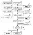
- the block diagram which shows the control structure of the forklift which concerns on an Example.
- the flowchart which shows the procedure of the process which acquires the height data of a pallet with a laser sensor in an initial position.
- the figure for demonstrating the method of calculating the length and center position of the point group which comprise the straight line extracted from the acquired distance data The figure for demonstrating the method to detect the opening of a pallet.
- the flowchart which shows the procedure of the process which pinpoints the position and direction of the center of a pallet front surface from the distance data acquired by the laser sensor, when a forklift moves from an initial position to a pick-up position.
- the figure which shows typically the state which is controlling the height of a fork in order to irradiate the front surface of a pallet with a laser beam.
- the flowchart which shows the process sequence of the movement control of a forklift when moving a forklift to a loading position.
- the laser sensor may be disposed above the lower surface of the fork. According to such a configuration, the laser sensor can be prevented from being damaged even if the fork contacts the floor or the ground.
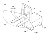
- the forklift 10 is an unmanned forklift, and includes a vehicle body 30, a mast 24, a fork 22, a lift chain 26, a laser sensor 20, and a control device 70.
- the vehicle body 30 includes a front wheel 28F and a rear wheel 28R on each of both side surfaces thereof.
- One of the rear wheels 28R is connected to a drive wheel motor 90 (shown in FIG. 3) via a drive mechanism (not shown), and is driven to rotate by the drive wheel motor 90.
- the rear wheels 28R connected to the drive wheel motor 90 are also connected to a steering device 94 (shown in FIG. 3), and the direction of the wheels is adjusted by the steering device 94.
- the other of the rear wheels 28 ⁇ / b> R is a caster wheel that rotates and steers following the traveling of the vehicle body 30.
- the mast 24 is a column attached to the front surface of the vehicle body 30 and its axis extends in the vertical direction.
- the fork 22 is attached to the mast 24 so as to be movable in the vertical direction. Further, the fork 22 can swing with respect to the mast 24 by a tilt mechanism (not shown).
- the fork 22 has a pair of claws 22a and 22b. The claws 22a and 22b are disposed at positions separated from each other in the left-right direction of the vehicle body 30 and extend from the mast 24 side toward the front of the vehicle body 12.
- the lift chain 26 is installed on the mast 24 and is engaged with the fork 22. When the lift chain 26 is driven by a fork lifting device 48 (shown in FIG. 3), the fork 22 is lifted and lowered.
- the vertical position of the fork 22 can be specified by the drive amount of the fork lifting device 48.
- the laser sensor 20 irradiates laser light and measures the distance from the reflected light of the irradiated laser light to a peripheral object.
- the laser sensor 20 also moves up and down, so that the position in the height direction of the laser light emitted from the laser sensor 20 also changes.
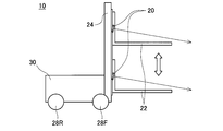
- the laser sensor 20 irradiates a region 50 (see FIG. 1) in a predetermined angular range ahead of the forklift 10 while moving up and down in the vertical direction.
- the laser light emitted from the laser sensor 20 is scanned in the horizontal direction and the height direction (two-dimensional), and distance data 80 in front of the forklift 10 is acquired.
- the three-dimensional distance data acquired by the laser sensor 20 is input to the control device 70 (shown in FIG. 3).
- control device 70 executes a process stored in the memory to recognize the pallet 100 by the laser sensor 20 and move the forklift 10 to a position for unloading the recognized pallet 100. To do. Specifically, at the time of initial observation of the pallet 100 to be unloaded, the control device 70 first lowers the laser sensor 20 while detecting the position of the laser sensor 20 in the height direction, and at the same time, the laser sensor 20. Based on the distance data acquired by the above, a process for specifying the center height of the front surface of the pallet 100 is executed. Next, the control device 70 specifies the position and direction of the pallet 100 based on distance data obtained by observing the vicinity of the center height of the front surface of the specified pallet 100.
- the acquisition of the distance data is executed in a state where the forklift 10 is stopped in the vicinity of the pallet 100 to be picked up. That is, as shown in FIG. 4, first, the control device 70 drives the one rear wheel 28 ⁇ / b> R so that the pallet 100 is positioned in front of the vehicle body 30, thereby causing the forklift 10 to approach the pallet 100. That is, in order to observe the pallet 100 with the laser sensor 20, the forklift 10 is moved to the initial position in front of the pallet (S10).
- the position on which the luggage (pallet 100) is placed is predetermined. For this reason, the initial position at which the forklift 10 is stopped is determined in advance from the position where the pallet 100 is placed. For this reason, the control device 70 automatically drives the forklift 10 by driving the drive wheel motor 90 and the steering device 94 to a preset initial position.
- the forklift 10 When the forklift 10 is driven by the driver, the forklift 10 may be moved to the initial position by the driver, and then the distance data generation process may be started by a switch operation of the driver of the forklift 10.
- the control device 70 drives the fork lifting device 48 to acquire scan data with the laser sensor 20 while lowering the fork 22 (S14). That is, the laser sensor 20 irradiates the laser beam while scanning in the horizontal direction and detects reflected light of the irradiated laser beam. On the other hand, since the fork lifting device 48 lowers the fork 22, the laser sensor 20 moves downward. For this reason, the laser beam emitted from the laser sensor 20 is also scanned in the vertical direction. Therefore, the laser beam from the laser sensor 20 is scanned in the horizontal direction and the vertical direction by the processing in step S14, and the observation point group of the observation target region 60 can be acquired by detecting the reflected light. Note that the function of the control device 70 realized by the process of raising and lowering the fork in steps S12 and S14 corresponds to the sensor movement control unit 44 shown in FIG.
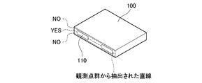
- the control device 70 sequentially performs the process of step S16 on the observation point group acquired by the laser sensor 20. Specifically, the control device 70 first determines whether or not a straight line can be extracted from the observation point group. As shown in FIG. 5, the observation point group by the reflected light reflected from the front surface of the pallet 100 is located on the same plane. For this reason, the observation point group by the reflected light reflected from the front surface of the pallet 100 forms a straight line. In addition, for the extraction of a straight line, for example, a known algorithm called robust estimation such as RANSAC can be used.
- the control device 70 determines whether or not it is equal to the width of the pallet 100 by comparing the length obtained by the equation (1) with the width (set value) of the pallet 100.
- the control device 70 determines whether or not the extracted straight line is composed of three line segments. Specifically, the extracted straight lines are clustered by the Euclidean distance. That is, as shown in FIGS. 5 and 7, two openings 110 (holes into which the claws 22 a and 22 b of the fork 22 are inserted) are formed on the front surface of the pallet 100. For this reason, the straight line extracted from the front surface of the pallet 100 is divided by the opening 110 on the front surface of the pallet 100. Therefore, when the measured height by the laser sensor 20 exists in the range of the pallet opening 110, the extracted straight lines are clustered by three line segments (that is, the number of clusters is 3 (YES in FIG. 7).
- a known method such as a k-means method or a kd-tree method can be used.
- control device 70 controls the fork elevating device 48 to elevate and lower the fork 22, it is possible to know the position of the fork 22 in the vertical direction. Since the laser sensor 20 is attached to the fork 22, the control device 70 (sensor position detection unit 46 shown in FIG. 3) can know the position of the laser sensor 20 in the height direction. Therefore, if all the conditions in the processing of step S16 described above (YES in S16), control device 70 determines the measurement height of the current of the laser sensor 20 starts the height of the pallet aperture 110 and (h A) Then, the current measurement height is recorded (S18). If at least one of the conditions is not satisfied in step S16 (NO in S16), the control device 70 returns to the process of step S14.
- control device 70 drives the fork lifting device 48 again, and acquires scan data by the laser sensor 20 while lowering the fork 22 (S20).
- control device 70 sequentially performs the process of step S22 on the observation point group acquired by the laser sensor 20. Since the process of step S22 is the same as the process of step S16, detailed description is abbreviate
- the control device 70 determines that the current measured height of the laser sensor 20 is the end height (h B of the opening 110 of the pallet 100). ) And the current measured height is recorded (S24).
- control device 70 calculates the height h P of the center of the pallet 100 from h A and h B obtained by performing the processing of steps S16 and S22 described above, using the following equations (2) and (3). Then, the vertical width H P (pallet height data 62) of the pallet opening 110 is obtained (S26). Note that the function of the control device 70 realized by the processing of steps S10 to S24 corresponds to the palette recognition unit 36 shown in FIG.
- the control device 70 executes a process for detecting the center position of the front surface of the pallet 100 shown in FIG. 8 and a travel control process for the forklift 10 shown in FIG. That is, the control device 70 detects the center position of the front surface of the pallet 100 by the laser sensor 20 and controls the drive wheel motor 90 and the steering device 94 using the detection result, thereby moving the forklift 10 to the unloading position. Move. First, processing for detecting the center position of the front surface of the pallet 100 by the control device 70 will be described. As shown in FIG.
- the distance L and pallet height H p of the laser sensor 20 and the pallet 100 can be calculated from the sensor position detecting unit 46 and the pallet height data 62. Further, the depression angle ⁇ provided in the laser sensor 20 is known. Accordingly, the distance between the laser sensor 20 and the pallet 100 L, from the pallet height H p, and the depression angle phi, seeking sensor height H s, to control the height of the fork 22 so as to satisfy the above equation (4). Thereby, even when a vehicle shakes or an observation error occurs, the laser light does not come off the pallet 100, and accurate follow-up control can be performed.
- the control device 70 performs the process of step S34 on the extracted straight line. Specifically, the control device 70 first determines whether or not the length of the point group constituting the straight line extracted in step S32 is approximately equal to the width of the pallet 100 (S34). The length of the point group constituting the straight line is obtained by the above-described equation (1) by using, for example, observation points having the maximum value and the minimum value in the x direction and the maximum value and the minimum value in the y direction of the point group. be able to. The control device 70 determines whether or not it is equal to the width of the pallet 100 by comparing the length obtained by the expression (1) with the width (set value) of the pallet 100.
- the control device 70 causes the maximum value and the minimum value in the x direction and the maximum value and the minimum value in the y direction of the observation point group acquired by the laser sensor 20.
- the detection of the center position Pc in the x direction and the y direction on the front surface of the pallet 100 can be obtained by, for example, the following equations (5) and (6).
- the control device 70 sets the target position / orientation x ref , y ref , ⁇ ref of the vehicle body 30 at the current time based on the trajectory data 86, and pallet position / direction data.
- Deviations x e , y e , ⁇ e are calculated from the current position / azimuth x veh , y veh , ⁇ veh of the vehicle body 30 calculated from 84, and the calculated deviations x e , y e , ⁇ e are used as vehicle coordinates. Conversion into a system (S52).
- the control device 70 controls the speed and steering angle of the drive wheels based on the obtained translational speed and angular speeds v out and ⁇ out (S56). That is, based on the control command value (v out , ⁇ out ), the control device 70 obtains a driving wheel speed command value and a steering angle command value that realize this based on a geometric calculation, and respectively controls the driving wheel motor 90 and a steering wheel. Output to device 94.
- the function of the control device 70 realized by the above processing corresponds to the drive wheel / steering control unit 42 shown in FIG.
- the laser sensor 20 is attached to the fork 22. For this reason, when the fork 22 moves up and down, the laser sensor 20 also moves up and down accordingly. Therefore, the shape of the front surface of the pallet 100 can be measured only by the laser sensor 20 scanning the laser beam in the horizontal direction while raising and lowering the fork 22. In addition, since the position, direction, and width of the pallet 100 are specified from the observation point group on the front surface of the pallet 100, it is possible to detect a positional deviation in the lateral direction of the pallet 100 and a deviation related to rotation.
- the driving wheel / steering control unit 42 is an example of the “control unit”, and the calculation unit 34, the pallet recognition unit 36, the trajectory / speed planning unit 38, and the driving / steering command unit 40 are the “guidance planning unit” in the claims.
- the sensor movement control unit 44 is an example of an “elevating mechanism”.
- the height of the pallet 100 (the position of the opening 110 in the height direction) can be detected by a change in the beam length of the laser light.
- a location where the beam length is remarkably increased can be the upper end of the pallet opening 110
- a location where the beam length is remarkably shortened can be the lower end of the pallet opening 110.
Abstract
フォークリフト(10)は、車体(30)と、車体(30)に取付けられているフォーク(22)と、車体(30)の位置及び向きを調整する制御部(42)と、フォーク(22)の前方に設定された空間内に存在する物体までの距離データを計測するレーザセンサ(20)と、レーザセンサ(20)で計測された距離データに荷又はパレット(100)が含まれる場合に、距離データから車体(30)を荷又はパレット(100)の荷取り位置まで移動させる軌道データを生成し、その生成した軌道データを用いて制御部に指令を与える制御指令部(38、40)と、を備える。
Description
本出願は、2015年4月16日に出願された日本国特許出願第2015-084522号に基づく優先権を主張する。その出願の全ての内容はこの明細書中に参照により援用される。本明細書に開示の技術は、フォークリフトに関する。
フォークリフトによる荷取り作業の際、フォークと荷取り対象となる荷又はパレットとの干渉を避ける必要がある。日本国特許公開公報第2005-89013号に開示のフォークリフトでは、反射型光センサによって、パレットの開口の上端および下端を検出する。そして、フォークの上面とパレットの開口の上端とのクリアランス、および、フォークの下面とパレットの開口の下端とのクリアランスを算出し、これらクリアランスが適切な値となるようにフォークの位置を調整している。
フォークリフトに正確な荷取り作業を行うためには、フォークリフトを荷取り対象となる荷又はパレットの荷取り位置まで正確に移動させなければならない。しかし、従来の技術では、荷取り対象となる荷又はパレットの荷取り位置に正確に位置決めできない場合があった。例えば、日本国特許公開公報第2005-89013号の技術では、パレットの高さ方向のずれを検出できるものの、横方向のずれや、パレットの向きに関するずれを検出することはできない。このため、フォークリフトをパレットの荷取り位置に正確に位置決めすることができない場合があった。
本明細書は、正確な荷取り作業が可能となるフォークリフトを開示する。
本明細書に開示するフォークリフトは、車体と、車体に取付けられているフォークと、車体の位置及び向きを調整する制御部と、フォークの前方に設定された空間内に存在する物体までの距離データを計測するレーザセンサと、レーザセンサで計測された距離データに荷取り対象となる荷又はパレットが含まれる場合に、当該距離データから車体を当該荷又はパレットの荷取り位置まで移動させる軌道データを生成し、その生成した軌道データを用いて制御部に指令を与える制御指令部とを備える。
上記のフォークリフトは、フォークの前方に設定された空間内に存在する物体までの距離データを計測するレーザセンサを備えている。したがって、荷取り対象となる荷又はパレットの高さ方向のずれに加えて、横方向のずれや、荷又はパレットの向きに関するずれまで検出することができる。そして、レーザセンサで計測された距離データに荷取り対象となる荷又はパレットが含まれる場合には、その距離データから車体を当該荷又はパレットの荷取り位置まで移動させる軌道データを生成し、その生成した軌道データを用いて車体を移動させる。このため、フォークリフトを荷又はパレットの荷取り位置に正確に位置決めすることができる。
以下に説明する実施例の主要な特徴を列記しておく。なお、以下に記載する技術要素は、それぞれ独立した技術要素であって、単独であるいは各種の組合せによって技術的有用性を発揮するものであり、出願時請求項記載の組合せに限定されるものではない。
(特徴1) 本明細書に開示するフォークリフトにおいて、制御指令部は、レーザセンサで計測された距離データにパレットが含まれる場合に、当該距離データから当該パレットの位置及び向きを特定し、それら特定したパレットの位置及び向きに基づいて軌道データを生成してもよい。このような構成によると、生成された軌道データに基づいて、車体を荷取り位置まで、正確に移動させることができる。
(特徴2) 本明細書に開示するフォークリフトにおいて、レーザセンサは、レーザ光を第1の方向に走査することで走査平面内の物体との距離を計測するレーザセンサであってもよい。また、レーザセンサはフォークに取付けられており、フォークを第1の方向とは異なる方向に移動させることで、レーザセンサは、フォークの前方に設定された空間内に存在する物体までの3次元距離データを計測してもよい。このような構成によると、1次元走査型のレーザセンサであっても2次元走査が可能となり、フォークリフト周辺の物体の3次元距離データを得ることができる。
(特徴3) 本明細書に開示するフォークリフトは、フォークを車体に対して昇降させる昇降機構をさらに備えており、レーザセンサは、フォークが昇降運動することで、フォークの前方に設定された空間内に存在する物体までの3次元距離データを計測してもよい。このような構成によると、フォークを上下方向に昇降させる昇降機構を利用して、レーザセンサから照射されるレーザ光を第1の方向と交差する上下方向に走査することができる。このため、レーザセンサから照射されるレーザ光を2次元に走査することができ、フォークリフト周辺の物体の3次元距離データを得ることができる。
(特徴4) 本明細書に開示するフォークリフトは、フォークを車体に対して傾斜させるティルト機構をさらに備えており、レーザセンサは、フォークが傾斜運動することで、フォークの前方に設定された空間内に存在する物体までの3次元距離データを計測してもよい。このような構成によると、フォークを傾動させるティルト機構を利用して、レーザセンサから照射されるレーザ光を上下方向に走査することができる。このため、レーザセンサから照射されるレーザ光を2次元(例えば、水平方向及び上下方向の2次元)に走査することができ、周辺の物体の3次元距離データを得ることができる。
(特徴5) 本明細書に開示するフォークリフトにおいて、レーザセンサは、フォークの下面よりも上方に配置されていてもよい。このような構成によると、フォークが床や地面に接触しても、レーザセンサが破損することを防止できる。
(特徴6) 本明細書に開示するフォークリフトにおいて、レーザセンサは、当該レーザセンサから照射されるレーザ光が斜め下方に照射されるように、水平方向に対して俯角を付けてフォークに取付けられていてもよい。このような構成によると、レーザセンサがフォークの上方に取付けられる場合でも、床に置かれたパレット等を認識することができる。
(特徴7) 本明細書に開示するフォークリフトにおいて、制御指令部は、レーザセンサで計測された3次元距離データに荷取り対象となる荷又はパレットが含まれる場合であって、当該3次元距離データから車体を当該荷又はパレットの荷取り位置まで移動させる間、レーザセンサから照射されるレーザ光が当該荷又はパレットの前面の中央に照射されるようにフォークの運動を制御してもよい。このような構成によると、車体移動中に常に荷又はパレットの観測を行うことができ、フォークリフトを荷取り位置まで正確に移動させることができる。
本実施例のフォークリフト10について、図面を参照しながら説明する。図1に示すように、フォークリフト10は、無人フォークリフトであり、車体30と、マスト24と、フォーク22と、リフトチェーン26と、レーザセンサ20と、制御装置70とを備えている。
車体30は、その両側面のそれぞれに前輪28F及び後輪28Rを備えている。後輪28Rの一方は、図示しない駆動機構を介して駆動輪モータ90(図3に図示)に接続されており、駆動輪モータ90によって回転駆動されるようになっている。また、駆動輪モータ90に接続された後輪28Rは、操舵装置94(図3に図示)にも接続されており、操舵装置94によって車輪の向きが調整される。後輪28Rの他方は、キャスタ輪であり、車体30の走行に追従して回転及び操舵する。制御装置70が駆動輪モータ90及び操舵装置94を制御することより、車体30は路面を走行すると共に、車体30の進行方向を変えることができる。
マスト24は、車体30の前面に取付けられている支柱であり、その軸線は上下方向に伸びている。フォーク22は、マスト24に上下方向に移動可能に取付けられている。また、フォーク22は、図示しないティルト機構によって、マスト24に対して揺動可能となっている。フォーク22は、一対のツメ22a,22bを有している。ツメ22a,22bは、車体30の左右方向に互いに離間した位置に配置されており、マスト24側から車体12の前方に向かって伸びている。リフトチェーン26は、マスト24に設置されており、フォーク22と係合している。リフトチェーン26がフォーク昇降装置48(図3に図示)により駆動されると、それによってフォーク22が昇降される。フォーク22の上下方向の位置は、フォーク昇降装置48の駆動量によって特定可能となっている。
レーザセンサ20は、フォーク22に取付けられ、フォーク22と一体となって上下方向に昇降する。レーザセンサ20が取付けられる位置は、ツメ22a、22bの間であって、フォーク22のバックレスト面より奥側(車体12側)に配置されている。レーザセンサ20は、ツメ22a、22bの下面よりも上方に配置されている。レーザセンサ20は、照射されるレーザ光が斜め下方に照射されるように、水平方向に対して俯角を付けてフォーク22に取付けられている。レーザセンサ20は、1方向(本実施例では水平方向)にレーザ光を走査する1次元走査型のレーザセンサである。レーザセンサ20は、レーザ光を照射するとともにその照射したレーザ光の反射光から周辺物体までの距離を計測する。フォーク22が昇降すると、レーザセンサ20も昇降するため、レーザセンサ20から照射されるレーザ光の高さ方向の位置も変化する。本実施例では、図2に示すように、レーザセンサ20は、上下方向に昇降しながら、フォークリフト10の前方の所定の角度範囲の領域50(図1参照)にレーザ光を照射する。これにより、レーザセンサ20から照射されるレーザ光は水平方向及び高さ方向(2次元)に走査され、フォークリフト10の前方の距離データ80が取得される。レーザセンサ20で取得される3次元距離データは、制御装置70(図3に図示)に入力される。
なお、レーザセンサ20としては、例えば、北陽電機製のUTM-30LXやSICK社製LMS100等を用いることができる。
制御装置70は、CPU等を備えたマイクロプロセッサによって構成されている。制御装置70は、車体30に搭載されている。制御装置70は、上述したレーザセンサ20と、一方の後輪28Rを駆動する駆動輪モータ90と、一方の後輪28Rの操舵角を調整する操舵装置94と、フォーク22の昇降を行うフォーク昇降装置48等に接続されており、これらの動作を制御する。
すなわち、制御装置70は、駆動輪モータ90及び操舵装置94を駆動することで、フォークリフト10の進行方向及び走行速度を制御する。すなわち、制御装置70は、駆動輪モータ90及び操舵装置94に制御指令値を出力することで、一方の後輪28Rを駆動する。これによって、フォークリフト10の進行方向、走行速度及び走行経路等が制御される。制御装置70は、一方の後輪28Rの、操舵装置94による操舵角と、駆動輪モータ90からの信号に基づく回転速度から、フォークリフト10の実際の位置及び速度を特定することができる。なお、制御装置70によるフォークリフト10の進行方向及び走行速度の制御については、従来公知の方法で行うことができるため、ここではその詳細な説明は省略する。
また、制御装置70は、メモリに記憶されているプログラムを実行することで、レーザセンサ20によりパレット100を認識し、その認識したパレット100を荷取るための位置にフォークリフト10を移動させる処理を実行する。具体的には、荷取り対象となるパレット100の初期観測時においては、制御装置70は、まず、レーザセンサ20の高さ方向の位置を検出しながらレーザセンサ20を下降させると共に、レーザセンサ20により取得される距離データに基づいて、パレット100の前面の中央の高さを特定する処理を実行する。次に、制御装置70は、特定したパレット100の前面の中央の高さ付近を観測した距離データに基づいて、パレット100の位置及び方向を特定する。次いで、特定したパレット100の位置及び方向に基づいて車体が走行すべき軌道データを生成する処理を実行する。次いで、生成した軌道データと、パレット100の位置及び方向に基づいて駆動・操舵データを生成する処理を実行し、最後に、生成した駆動・操舵データに基づいて車体を駆動する処理を実行する。すなわち、制御装置70は、図3に示すように、パレット認識部36、軌道・速度計画部38、駆動・操舵指令部40、駆動輪・操舵制御部42、センサ移動制御部44及びセンサ位置検出部46として機能する。制御装置70が上述した各部32~46として機能することで、パレット100の位置、方向及び幅が特定され、特定されたパレット100の位置及び方向に基づいて車体30が荷取り位置まで移動する。各部32~46の詳細については、以下で説明する制御装置70で行われる処理とともに説明する。
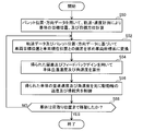
次に、制御装置70によって、パレット100の荷取り位置までフォークリフト10を移動させる処理について説明する。まず、荷取り対象となるパレット100の距離データ80を取得し、その距離データからパレット100の高さ及び幅を認識する処理について説明する。距離データの取得は、荷取り対象となるパレット100の近傍にフォークリフト10が停止した状態で実行される。すなわち、図4に示すように、制御装置70は、まず、車体30の前方にパレット100が位置するように、一方の後輪28Rを駆動して、パレット100に対してフォークリフト10を接近させる。すなわち、パレット100をレーザセンサ20によって観測するために、フォークリフト10をパレット前方の初期位置へ移動させる(S10)。例えば、工場内で荷物を運搬するフォークリフト10では、荷物(パレット100)が載置される位置は予め定められている。このため、フォークリフト10を停止させる初期位置は、パレット100が載置される位置から予め定められている。このため、制御装置70は、予め設定された初期位置まで、駆動輪モータ90及び操舵装置94を駆動してフォークリフト10を自動で移動させる。なお、フォークリフト10が運転者によって運転される場合は、運転者によってフォークリフト10が初期位置まで移動され、その後、フォークリフト10の運転者のスイッチ操作により距離データ生成処理が開始されてもよい。
次に、制御装置70は、フォーク昇降装置48を駆動して、レーザセンサ20を、観測対象領域60(図5に図示)の上限にレーザ光が照射されるように移動させる(S12)。観測対象領域60とは、パレット100が存在する可能性のある領域である。例えば、図5に示すように、荷物130はパレット100上に載置され、パレット100は台座120上に載置される場合であれば、パレット100が存在する可能性のある領域(高さ、幅)は、台座120とパレット100の寸法によって決まる。ステップS12では、パレット100が存在する可能性のある領域の上限までレーザセンサ20を移動させ、パレット100が確実に検出されるようにする。
次に、制御装置70は、フォーク昇降装置48を駆動して、フォーク22を下降させながら、レーザセンサ20でスキャンデータを取得する(S14)。すなわち、レーザセンサ20は、レーザ光を水平方向に走査しながら照射するとともにその照射したレーザ光の反射光を検出する。一方、フォーク昇降装置48がフォーク22を下降させるため、レーザセンサ20は下方向に移動する。このため、レーザセンサ20から照射されるレーザ光は、垂直方向にも走査される。したがって、ステップS14の処理によって、レーザセンサ20からのレーザ光は、水平方向及び垂直方向に走査され、その反射光を検出することで、観測対象領域60の観測点群を取得することができる。なお、上記のステップS12及びS14のフォークを昇降させる処理によって実現される制御装置70の機能が、図3に示すセンサ移動制御部44に相当する。
次に、制御装置70は、レーザセンサ20で取得した観測点群に対して、逐次的にステップS16の処理をする。具体的には、制御装置70は、まず、観測点群から直線が抽出できるか否かを判断する。図5に示すように、パレット100の前面から反射される反射光による観測点群は同一平面上に位置する。このため、パレット100の前面から反射される反射光による観測点群は、直線を構成する。なお、直線の抽出には、例えば、RANSACのようなロバスト推定と呼ばれる公知のアルゴリズムを用いることができる。
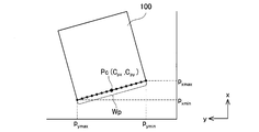
次に、制御装置70は、抽出された直線を構成する点群の長さが、パレット100の幅に概ね等しいか否かを判断する。ここで、パレット100の規格は既知であることが通常である。したがって、直線を構成する点群の長さと設定値(パレット100の規格から定められる値)を比較することによって、パレット100の前面の直線が抽出されているか否かを判断することができる。直線を構成する点群の長さWpは、例えば、図6に示すように、点群のx方向の最大値及び最小値pxmax,pxmin、y方向の最大値及び最小値pymax,pyminを持つ観測点を用いることによって、下式により求めることができる。

制御装置70は、式(1)により求められた長さをパレット100の幅(設定値)と照らし合わせることによって、パレット100の幅に等しいか否かを判断する。
次に、制御装置70は、抽出された直線が3本の線分で構成されているか否かを判断する。詳細には、抽出された直線をユークリッド距離でクラスタリングする。すなわち、図5,7に示すように、パレット100の前面には2つの開口部110(フォーク22のツメ22a,22bが挿し込まれる孔)が形成されている。このため、パレット100の前面から抽出される直線は、パレット100の前面の開口部110によって分断される。したがって、レーザセンサ20による計測高さが、パレット開口部110の範囲に存在するとき、抽出された直線は3本の線分でクラスタリングされる(すなわち、クラスタ数が3となる(図7でYESと示された線分)。なお、クラスタリングには、例えば、k-means法やkd-tree法のような公知の方法を用いることができる。
ここで、制御装置70は、フォーク昇降装置48を制御してフォーク22を昇降するため、フォーク22の上下方向の位置を知ることができる。レーザセンサ20は、フォーク22に取付けられているため、制御装置70(図3に示すセンサ位置検出部46)は、レーザセンサ20の高さ方向の位置を知ることができる。このため、上述したステップS16の処理における条件を全て満たす場合(S16でYES)、制御装置70は、現在のレーザセンサ20の計測高さをパレット開口部110の開始高さ(hA)と判断し、現在の計測高さを記録する(S18)。ステップS16において、少なくともいずれか一つの条件を満たさない場合(S16でNO)は、制御装置70はステップS14の処理へ戻る。
次に、制御装置70は、再びフォーク昇降装置48を駆動して、フォーク22を下降させながら、レーザセンサ20でスキャンデータを取得する(S20)。次いで、制御装置70は、レーザセンサ20で取得した観測点群に対して、逐次的にステップS22の処理をする。ステップS22の処理については、ステップS16の処理と同様であるため、詳細な説明は省略する。ステップS22の処理において、少なくともいずれか一つの条件を満たさない場合(S22でNO)、制御装置70は、現在のレーザセンサ20の計測高さはパレット100の開口部110の終了高さ(hB)であると判断し、現在の計測高さを記録する(S24)。ステップS22の処理において条件を全て満たす場合(S22でYES)、レーザ光が走査される位置はパレット100の開口部110の位置であるとし、制御装置70はステップS20の処理へ戻る。なお、上記のステップS16及びS22の処理のうち、レーザセンサ20の高さを認識する制御装置70の機能が、図3に示すセンサ位置検出部46に相当する。
次に、制御装置70は、上述したステップS16及びS22の処理を行うことによって得られたhA及びhBから、下式(2)及び(3)により、パレット100の中心の高さhP及びパレット開口部110の上下方向の幅HP(パレット高さデータ62)を求める(S26)。なお、上記のステップS10~S24の処理によって実現される制御装置70の機能が、図3に示すパレット認識部36に相当する。

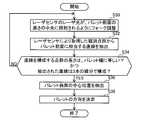
次に、フォークリフト10を初期位置から荷取り位置まで移動させる際に、制御装置70によって実行される処理について説明する。フォークリフト10を初期位置から荷取り位置まで移動させる際、制御装置70は、図8に示すパレット100の前面の中心位置を検出する処理と、図10に示すフォークリフト10の走行制御処理を実行する。すなわち、制御装置70は、レーザセンサ20によってパレット100の前面の中心位置を検出しながら、その検出結果を用いて駆動輪モータ90及び操舵装置94を制御することで、フォークリフト10を荷取り位置まで移動させる。まず、制御装置70によるパレット100の前面の中心位置を検出する処理について説明する。図8に示すように、まず、制御装置70は、車体30が初期位置から荷取り位置まで移動する間、レーザセンサ20で観測されるパレット高さデータ62に基づいて、レーザセンサ20のレーザ光が、常にパレット100の前面の高さの中央に照射されるように、フォーク昇降装置48により、フォーク22の高さを調整する(S30、図9に示す状態)。

図9に示すように、レーザセンサ20とパレット100との距離L及びパレット高Hpは、センサ位置検出部46及びパレット高さデータ62から算出することができる。また、レーザセンサ20に設けられた俯角φは既知である。したがって、レーザセンサ20とパレット100との距離L、パレット高Hp及び俯角φから、センサ高Hsを求め、上式(4)を満足するようにフォーク22の高さを制御する。これにより、車両の揺れや観測誤差が生じた場合でも、レーザ光がパレット100から外れることがなく、正確な追従制御ができる。
次に、制御装置70は、センサ高Hsにおいて、レーザセンサ20で取得した観測対象領域60内に存在する観測点群から、パレット前面に相当する直線を抽出する(S32)。直線の抽出には、例えば、RANSACのような公知のアルゴリズムを用いることができる。
次に、制御装置70は、抽出された直線に対し、ステップS34の処理を行う。具体的には、制御装置70は、まず、ステップS32で抽出された直線を構成する点群の長さが、パレット100の幅に概ね等しいか否かを判断する(S34)。直線を構成する点群の長さは、例えば、点群のx方向の最大値及び最小値、y方向の最大値及び最小値を持つ観測点を用いることによって、上述した式(1)により求めることができる。制御装置70は、式(1)により求められた長さをパレット100の幅(設定値)と照らし合わせることによって、パレット100の幅に等しいか否かを判断する。
次に、制御装置70は、抽出された直線が3本の線分で構成されているか否かを判断する(S34)。具体的には、上述したステップS16における処理と同様であるため、ここではその詳細な説明は省略する。
上述したステップS34の処理において、少なくともいずれか一つの条件を満たさない場合(S34でNO)、制御装置70は、ステップS30に戻り処理を繰り返す。
上述したステップS34の処理において条件を全て満たす場合(S34でYES)、制御装置70は、レーザセンサ20により取得した観測点群のx方向の最大値及び最小値、y方向の最大値及び最小値を用いてパレット100前面のx方向及びy方向の中心位置Pc(Cpx,Cpy)を検出する(S36、図6を参照)。パレット100の前面のx方向及びy方向の中心位置Pcの検出は、例えば、下式(5)及び(6)により求めることができる。

次に、制御装置70は、パレット100の方向を決定する(S38)。パレット100の方向の決定は、例えば、パレット認識部36及びセンサ位置検出部46によって、抽出された直線の方向をパレット100の側面の法線ベクトル、当該直線に直交する方向をパレット100前面の法線ベクトルとすることで、パレットの方向を求めることができる。これによって、パレット100の位置及び方向を特定することができ、パレット100の位置及び方向を特定したパレット位置・方向データ84が得られる。なお、上記のステップS30~S38の処理によって実現される制御装置70の機能が、図3に示すパレット認識部36に相当する。
次に、制御装置70によるフォークリフト10の走行制御処理を図10を用いて説明する。図10に示すように、制御装置70は、図4に示す処理を実行することで取得したパレット位置・方向データ84に基づいて、パレット100の荷取り位置(最終目標位置及び最終目標方向)に車体30を移動するための軌道計画を作成し、作成した軌道計画に基づいて、現在位置(初期位置)から荷取り位置まで移動する間の各時刻における目標位置及び目標方位を算出する(S50)。具体的には、まず、制御装置70は、パレット位置・方向データ84からパレット100の荷取り位置(フォークリフト10の最終目標位置及び最終目標方位)と、現在の位置から荷取り位置まで移動する際に要する時間を決定し、これらから軌道計画及び速度計画を作成する。次いで、制御装置70は、作成した軌道計画と速度計画に基づいて、現時点から荷取り位置まで移動する間の各時刻での目標位置及び目標方位(軌道データ86)を算出する。軌道計画と速度計画には、例えば、直線補間やスプライン曲線による補間のような従来公知の方法を用いることができる。なお、上記の処理によって実現される制御装置70の機能が、図3に示す軌道・速度計画部38に相当する。
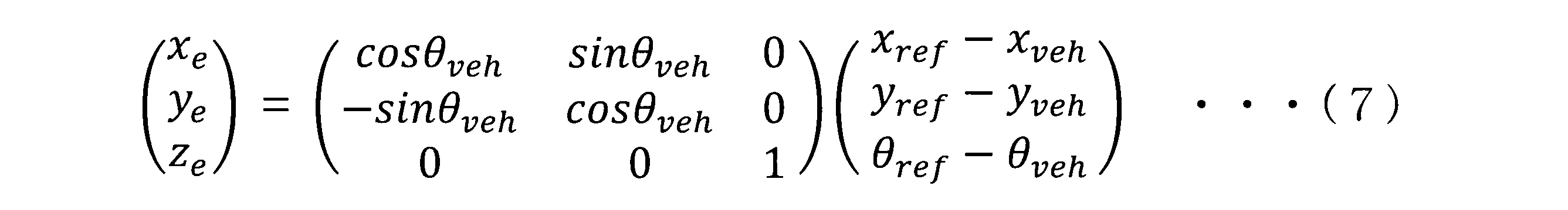
次に、制御装置70は、決定した軌道データ86(各時刻における目標位置及び目標方位)と、図8に示す処理によって取得されるパレット位置・方向データ84から特定されるフォークリフト10の現在の位置とに基づいて、荷取り位置(最終目標位置及び最終目標方向)まで車体30を移動するための制御指令値を生成する。すなわち、本実施例では、フォークリフト10が初期位置から荷取り位置まで移動する間も、レーザセンサ20によるパレット100の観測(図8の処理)が実行される。このため、レーザセンサ20により取得されるパレット位置・方向データ84から、現在のフォークリフトの位置(パレット100に対する相対的位置)及び方位を算出することができる。このため、まず、制御装置70は、式(7)に示すように、軌道データ86に基づく現在時刻での車体30の目標位置・方位xref,yref,θrefと、パレット位置・方向データ84から算出される車体30の現在位置・方位xveh,yveh,θvehとから偏差xe,ye,θeを算出し、その算出した偏差xe,ye,θeを車両座標系に変換する(S52)。
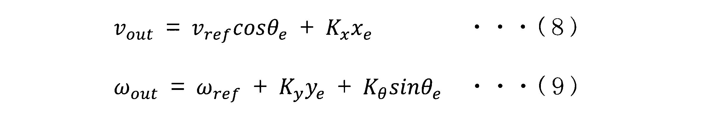
次に、制御装置70は、上記の式(7)より得られた偏差にフィードバックゲインKx,Ky,Kθを乗じて、車体30が出すべき実際の目標並進速度及び目標角速度vout,ωout(駆動・操舵データ88)を算出する(S54)。なお、車体30の目標並進速度及び目標角速度vout,ωout(すなわち、車両座標系での並進速度及び角速度)は、下記に示す式(8)及び(9)を用いて算出することができる。そして、図11に示すように、駆動・操舵データ88に基づいてフォークリフト10が移動することで、フォークリフト10は、パレット100に対して適切な位置及び向きとなるように調整される。なお、上記の処理によって実現される制御装置70の機能が、図3に示す駆動・操舵指令部40に相当する。
次に、制御装置70は、得られた並進速度及び角速度vout,ωoutを元に、駆動輪の速度及び操舵角を制御する(S56)。すなわち、制御装置70は、制御指令値(vout,ωout)に基づき、これを実現する駆動輪速度指令値と操舵角度指令値を幾何学的計算により求め、それぞれを駆動輪モータ90と操舵装置94へ出力する。なお、上記の処理によって実現される制御装置70の機能が、図3に示す駆動輪・操舵制御部42に相当する。
次に、制御装置70は、フォークリフト10が荷取り位置(最終目標位置及び最終目標方向)まで移動したかを判断する(S58)。フォークリフト10が荷取り位置まで移動していないと判断した場合(S58でNO)は、制御装置70は、ステップS52~S58を繰り返す。これによって、フォークリフト10が荷取り位置まで移動する。一方、フォークリフト10が荷取り位置まで移動したと判断した場合(S58でYES)は、図10に示す処理を終了する。
上述した実施例のフォークリフト10では、レーザセンサ20がフォーク22に取付けられている。このため、フォーク22が昇降すると、それに応じてレーザセンサ20も昇降する。したがって、フォーク22を昇降しながら、レーザセンサ20が水平方向にレーザ光を走査するだけで、パレット100の前面の形状を計測することができる。また、パレット100の前面の観測点群から、パレット100の位置、方向及び幅を特定するため、パレット100の横方向の位置ずれや、回転に関するずれを検出することができる。
また、上述した実施例のフォークリフト10では、レーザセンサ20で得られたパレット100の計測データに基づいて、車体30をパレット100の荷取り位置まで移動させる軌道データを生成し、その生成した軌道データを用いて車体30を移動させる。このため、フォークリフト10をパレット100の荷取り位置に正確に位置決めすることができる。
最後に、上述した実施例と請求項との対応関係を説明しておく。駆動輪・操舵制御部42が「制御部」の一例であり、演算部34、パレット認識部36、軌道・速度計画部38及び駆動・操舵指令部40が請求項でいう「誘導計画部」の一例であり、センサ移動制御部44が「昇降機構」の一例である。
以上、本実施例を詳細に説明したが、これらは例示にすぎず、特許請求の範囲を限定するものではない。特許請求の範囲に記載の技術には、以上に例示した具体例をさまざまに変形、変更したものが含まれる。
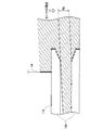
例えば、本実施例では、フォークを上下方向に昇降させることでレーザ光を上下方向に走査したが、本明細書に開示する技術は、このような構成に限られない。例えば、図12に示すように、フォークの先端を基端に対して傾動させるティルト機構を利用して、レーザセンサ20から照射されるレーザ光を上下方向に走査してもよい。
また、本実施例では、レーザセンサ20で得られた観測点群から水平方向に伸びる直線を抽出し、その線分の長さと線分の数(クラスタ数)を、パレット100の開口部110の特徴として捉え、これをもとにパレット100の高さを検出したが、本明細書に開示する技術は、レーザセンサ20から照射されるレーザ光のビーム長の変化を捉えてパレット100の高さを検出してもよい。例えば、レーザセンサ20から照射されるレーザ光を観測対象領域60の上限から下限まで走査すると、図13に示すように、レーザセンサ20から照射されるレーザ光のビーム長は、開口部110によって大きく変化する。このため、パレット100の高さ(開口部110の高さ方向の位置)は、レーザ光のビーム長の変化によって検出することができる。具体的には、ビーム長が顕著に大きくなった箇所をパレット開口部110の上端とし、ビーム長が顕著に短くなった箇所をパレット開口部110の下端とすることができる。より詳細には、観測対象領域60の上限から下方に向かってレーザスキャンを行うと、まず、レーザ光は、パレット100の上端を捉える。さらにレーザスキャンを続けていくと、照射されるレーザ光の高さが、開口部110に達したとき、照射されるレーザ光は開口部110内を通過し、レーザ光のビーム長が極端に長くなる位置が現れる。したがって、その高さを開口部110の上端と認識することができる。その後、レーザスキャンをさらに続け、照射されるレーザ光の高さが、開口部110の下端に達すると、レーザ光はパレット100の前面に照射され、レーザ光のビーム長が極端に短くなる。したがって、その高さを開口部110の下端と認識することができる。なお、パレットの仕様(開口部110の大きさ)が既知の場合、開口部110の上端又は下端の位置を検出できれば、パレット開口部110の中央部の高さを求めることができる。この場合、レーザ光を観測対象領域60の下限までレーザ光を走査する必要がなくなるため、リードタイムの低減が可能となる。なお、パレット100の高さの検出は、観測対象領域60の下限から上方に向かってレーザスキャンを行ってもよい。
本明細書または図面に説明した技術要素は、単独であるいは各種の組み合わせによって技術的有用性を発揮するものであり、出願時請求項記載の組み合わせに限定されるものではない。また、本明細書又は図面に例示した技術は複数目的を同時に達成するものであり、そのうちの一つの目的を達成すること自体で技術的有用性を持つものである。
Claims (8)
- 車体と、
前記車体に取付けられているフォークと、
前記車体の位置及び向きを調整する制御部と、
前記フォークの前方に設定された空間内に存在する物体までの距離データを計測するレーザセンサと、
前記レーザセンサで計測された距離データに荷取り対象となる荷又はパレットが含まれる場合に、当該距離データから前記車体を当該荷又はパレットの荷取り位置まで移動させる軌道データを生成し、その生成した軌道データを用いて前記制御部に指令を与える制御指令部と、を備えるフォークリフト。 - 前記制御指令部は、前記レーザセンサで計測された距離データにパレットが含まれる場合に、当該距離データから当該パレットの位置及び向きを特定し、それら特定したパレットの位置及び向きに基づいて前記軌道データを生成する、請求項1に記載のフォークリフト。
- 前記レーザセンサは、レーザ光を第1の方向に走査することで走査平面内の物体との距離を計測するレーザセンサであり、
前記レーザセンサは、前記フォークに取付けられており、前記フォークを前記第1の方向とは異なる方向に移動させることで、前記フォークの前方に設定された空間内に存在する物体までの3次元距離データを計測する、請求項1又は2に記載のフォークリフト。 - 前記フォークを前記車体に対して昇降させる昇降機構をさらに備えており、
前記レーザセンサは、前記フォークが昇降運動することで、前記フォークの前方に設定された空間内に存在する物体までの3次元距離データを計測する、請求項3に記載のフォークリフト。 - 前記フォークを前記車体に対して傾斜させるティルト機構をさらに備えており、
前記レーザセンサは、前記フォークが傾斜運動することで、前記フォークの前方に設定された空間内に存在する物体までの3次元距離データを計測する、請求項3に記載のフォークリフト。 - 前記レーザセンサは、前記フォークの下面よりも上方に配置されている、請求項3~5のいずれか一項に記載のフォークリフト。
- 前記レーザセンサは、当該レーザセンサから照射されるレーザ光が斜め下方に照射されるように、水平方向に対して俯角を付けて前記フォークに取付けられている、請求項6に記載のフォークリフト。
- 前記制御指令部は、前記レーザセンサで計測された3次元距離データに荷取り対象となる荷又はパレットが含まれる場合であって、当該3次元距離データから前記車体を当該荷又はパレットの荷取り位置まで移動させる間、前記レーザセンサから照射されるレーザ光が当該荷又はパレットの前面の高さの中央に照射されるように前記フォークの運動を制御する、請求項3~7のいずれかに記載のフォークリフト。
Priority Applications (3)
| Application Number | Priority Date | Filing Date | Title |
|---|---|---|---|
| CN201680021848.XA CN107428518B (zh) | 2015-04-16 | 2016-04-08 | 叉车 |
| EP16779991.5A EP3284712B1 (en) | 2015-04-16 | 2016-04-08 | Forklift |
| US15/566,463 US10414640B2 (en) | 2015-04-16 | 2016-04-08 | Forklift |
Applications Claiming Priority (2)
| Application Number | Priority Date | Filing Date | Title |
|---|---|---|---|
| JP2015-084522 | 2015-04-16 | ||
| JP2015084522A JP6469506B2 (ja) | 2015-04-16 | 2015-04-16 | フォークリフト |
Publications (1)
| Publication Number | Publication Date |
|---|---|
| WO2016167200A1 true WO2016167200A1 (ja) | 2016-10-20 |
Family
ID=57126576
Family Applications (1)
| Application Number | Title | Priority Date | Filing Date |
|---|---|---|---|
| PCT/JP2016/061599 WO2016167200A1 (ja) | 2015-04-16 | 2016-04-08 | フォークリフト |
Country Status (5)
| Country | Link |
|---|---|
| US (1) | US10414640B2 (ja) |
| EP (1) | EP3284712B1 (ja) |
| JP (1) | JP6469506B2 (ja) |
| CN (1) | CN107428518B (ja) |
| WO (1) | WO2016167200A1 (ja) |
Cited By (4)
| Publication number | Priority date | Publication date | Assignee | Title |
|---|---|---|---|---|
| EP3225584A1 (en) * | 2016-03-30 | 2017-10-04 | Kabushiki Kaisha Toyota Jidoshokki | Forklift |
| US9990535B2 (en) | 2016-04-27 | 2018-06-05 | Crown Equipment Corporation | Pallet detection using units of physical length |
| CN108692681A (zh) * | 2017-04-05 | 2018-10-23 | 村田机械株式会社 | 凹陷部检测装置、输送装置以及凹陷部检测方法 |
| CN113608275A (zh) * | 2021-07-20 | 2021-11-05 | 深圳市华星光电半导体显示技术有限公司 | 台车和二重感应器的校正治具及校正方法 |
Families Citing this family (31)
| Publication number | Priority date | Publication date | Assignee | Title |
|---|---|---|---|---|
| JP6520492B2 (ja) * | 2015-07-08 | 2019-05-29 | 株式会社豊田自動織機 | フォークリフトにおける荷取り方法及びフォークリフト |
| JP6972599B2 (ja) * | 2017-03-22 | 2021-11-24 | 日本電気株式会社 | 車載装置、荷役機、制御回路、制御方法、及びプログラム |
| JP6880884B2 (ja) | 2017-03-22 | 2021-06-02 | 日本電気株式会社 | 車載装置、荷役機、制御回路、制御方法、及びプログラム |
| CN110040669B (zh) * | 2018-01-17 | 2021-12-10 | 林德(中国)叉车有限公司 | 一种高位叉货辅助方法 |
| JP7036682B2 (ja) * | 2018-06-29 | 2022-03-15 | 三菱重工業株式会社 | フォークリフト装置、フォークリフト制御方法及びプログラム |
| CN110376601B (zh) * | 2018-08-14 | 2022-08-12 | 北京京东乾石科技有限公司 | 确定目标姿态的方法和系统 |
| JP7052666B2 (ja) * | 2018-10-04 | 2022-04-12 | トヨタ自動車株式会社 | 搬送装置 |
| CN109443201B (zh) * | 2018-10-31 | 2020-10-16 | 广东嘉腾机器人自动化有限公司 | 一种基于s300激光扫描传感器的栈板识别方法 |
| CN109462165A (zh) * | 2018-11-08 | 2019-03-12 | 西安西电电力系统有限公司 | 柔性直流换流阀功率模块的拆卸装置及控制方法 |
| CN109850810B (zh) * | 2019-03-13 | 2020-09-25 | 南京实邦智能科技有限公司 | 叉车运动控制方法及装置 |
| CN109878961A (zh) * | 2019-04-01 | 2019-06-14 | 深圳普智联科机器人技术有限公司 | 一种多层货架轮廓的初始化自动标定装置和方法 |
| CN110082720A (zh) * | 2019-04-04 | 2019-08-02 | 南京实邦智能科技有限公司 | 托盘信息采集装置、控制方法及托盘搬运车辆 |
| AU2020263470A1 (en) * | 2019-04-23 | 2021-12-23 | The Heil Co. | Refuse collection vehicle positioning |
| US11453550B2 (en) | 2019-04-23 | 2022-09-27 | The Heil Co. | Refuse collection vehicle controls |
| WO2020219764A1 (en) | 2019-04-23 | 2020-10-29 | The Heil Co. | Refuse container engagement |
| DE102019115864A1 (de) * | 2019-06-11 | 2020-12-17 | Jungheinrich Aktiengesellschaft | Flurförderzeug mit einer Fahrzeugsteuerung für einen automatischen Betrieb |
| JP7215356B2 (ja) * | 2019-06-26 | 2023-01-31 | 株式会社豊田自動織機 | フォークリフトの移載装置 |
| JP7151041B2 (ja) * | 2019-08-08 | 2022-10-12 | 株式会社豊田自動織機 | 位置姿勢推定装置 |
| JP7114536B2 (ja) * | 2019-09-10 | 2022-08-08 | 株式会社東芝 | 運搬装置 |
| CN110642187A (zh) * | 2019-09-11 | 2020-01-03 | 杭州易博特科技有限公司 | 托盘自动运输方法、系统及设备 |
| US11345577B2 (en) * | 2019-11-01 | 2022-05-31 | Teradyne, Inc. | Mobile automated guided vehicle pallet stacker and destacker system and method therefor |
| CN113031537B (zh) * | 2019-12-25 | 2022-05-17 | 北京极智嘉科技股份有限公司 | 机器人、货物运输方法、电子设备及存储介质 |
| JP7370288B2 (ja) * | 2020-03-19 | 2023-10-27 | 三菱重工業株式会社 | 演算装置、車両、荷役システム、演算方法及びプログラム |
| US11305786B2 (en) * | 2020-05-01 | 2022-04-19 | Autoguide, LLC. | Maintaining consistent sensor output |
| CN112830428B (zh) * | 2020-06-18 | 2022-09-13 | 陈凤阳 | 用于修正叉车agv测量叉取托盘姿态的系统及其工作方法 |
| CN111452053B (zh) * | 2020-06-18 | 2020-09-29 | 季华实验室 | 一种偏载调整方法、装置、顶升机构及移动机器人系统 |
| JP7318892B2 (ja) * | 2020-08-18 | 2023-08-01 | 株式会社Zmp | 自動運転フォークリフト |
| JP7086148B2 (ja) * | 2020-08-31 | 2022-06-17 | 三菱ロジスネクスト株式会社 | パレット検知装置、フォークリフト、パレット検知方法、及びプログラム |
| JP7179102B2 (ja) * | 2021-02-05 | 2022-11-28 | 三菱ロジスネクスト株式会社 | 移動体の制御方法、移動体及びプログラム |
| JP7207667B2 (ja) * | 2021-04-14 | 2023-01-18 | 株式会社Zmp | パレットの載置部構造 |
| EP4292975A1 (en) * | 2022-06-17 | 2023-12-20 | Effito Pte. Ltd. | Apparatus for identification and positioning and cargo transportation apparatus |
Citations (6)
| Publication number | Priority date | Publication date | Assignee | Title |
|---|---|---|---|---|
| JPS5957898A (ja) * | 1982-09-28 | 1984-04-03 | 株式会社豊田自動織機製作所 | 無人フオ−クリフトにおける荷役作業制御方法 |
| JPH0279398U (ja) * | 1988-12-05 | 1990-06-19 | ||
| JPH0539199A (ja) * | 1991-08-01 | 1993-02-19 | Toyota Autom Loom Works Ltd | バーコード読み取り装置 |
| JPH11278799A (ja) * | 1998-03-24 | 1999-10-12 | Mitsubishi Electric Corp | 無人フォークリフトにおける荷取り制御装置および無人フォークリフトにおける荷取り制御方法 |
| JP2005089013A (ja) * | 2003-09-12 | 2005-04-07 | Nippon Yusoki Co Ltd | フォークリフト |
| EP1995188B1 (en) * | 2007-05-22 | 2011-08-31 | Strömberg Distribution AB | Control system for the management of pallets in warehouses |
Family Cites Families (8)
| Publication number | Priority date | Publication date | Assignee | Title |
|---|---|---|---|---|
| DE10323641A1 (de) * | 2003-05-26 | 2005-01-05 | Daimlerchrysler Ag | Bewegliche Sensoreinrichtung am Lastmittel eines Gabelstaplers |
| US8192137B2 (en) | 2004-05-03 | 2012-06-05 | Jervis B. Webb Company | Automatic transport loading system and method |
| CN201237644Y (zh) * | 2008-03-21 | 2009-05-13 | 上海海镭激光科技有限公司 | 一种叉车与装载机倒车报警装置 |
| BE1018160A3 (nl) * | 2008-05-26 | 2010-06-01 | Egemin Nv | Automatisch gestuurd voertuig en werkwijze voor het sturen daarbij toegepast. |
| JP2010189130A (ja) | 2009-02-18 | 2010-09-02 | Nippon Yusoki Co Ltd | フォークリフトの荷役支援装置 |
| US8538577B2 (en) | 2010-03-05 | 2013-09-17 | Crown Equipment Limited | Method and apparatus for sensing object load engagement, transportation and disengagement by automated vehicles |
| KR101397342B1 (ko) * | 2012-02-29 | 2014-05-20 | 부산대학교 산학협력단 | 무인지게차의 팔레트 자율하역 장치 및 방법 |
| US8965561B2 (en) * | 2013-03-15 | 2015-02-24 | Cybernet Systems Corporation | Automated warehousing using robotic forklifts |
-
2015
- 2015-04-16 JP JP2015084522A patent/JP6469506B2/ja active Active
-
2016
- 2016-04-08 CN CN201680021848.XA patent/CN107428518B/zh active Active
- 2016-04-08 WO PCT/JP2016/061599 patent/WO2016167200A1/ja active Application Filing
- 2016-04-08 US US15/566,463 patent/US10414640B2/en active Active
- 2016-04-08 EP EP16779991.5A patent/EP3284712B1/en active Active
Patent Citations (6)
| Publication number | Priority date | Publication date | Assignee | Title |
|---|---|---|---|---|
| JPS5957898A (ja) * | 1982-09-28 | 1984-04-03 | 株式会社豊田自動織機製作所 | 無人フオ−クリフトにおける荷役作業制御方法 |
| JPH0279398U (ja) * | 1988-12-05 | 1990-06-19 | ||
| JPH0539199A (ja) * | 1991-08-01 | 1993-02-19 | Toyota Autom Loom Works Ltd | バーコード読み取り装置 |
| JPH11278799A (ja) * | 1998-03-24 | 1999-10-12 | Mitsubishi Electric Corp | 無人フォークリフトにおける荷取り制御装置および無人フォークリフトにおける荷取り制御方法 |
| JP2005089013A (ja) * | 2003-09-12 | 2005-04-07 | Nippon Yusoki Co Ltd | フォークリフト |
| EP1995188B1 (en) * | 2007-05-22 | 2011-08-31 | Strömberg Distribution AB | Control system for the management of pallets in warehouses |
Cited By (5)
| Publication number | Priority date | Publication date | Assignee | Title |
|---|---|---|---|---|
| EP3225584A1 (en) * | 2016-03-30 | 2017-10-04 | Kabushiki Kaisha Toyota Jidoshokki | Forklift |
| US9990535B2 (en) | 2016-04-27 | 2018-06-05 | Crown Equipment Corporation | Pallet detection using units of physical length |
| CN108692681A (zh) * | 2017-04-05 | 2018-10-23 | 村田机械株式会社 | 凹陷部检测装置、输送装置以及凹陷部检测方法 |
| TWI758459B (zh) * | 2017-04-05 | 2022-03-21 | 日商村田機械股份有限公司 | 凹陷部檢測裝置、搬送裝置及凹陷部檢測方法 |
| CN113608275A (zh) * | 2021-07-20 | 2021-11-05 | 深圳市华星光电半导体显示技术有限公司 | 台车和二重感应器的校正治具及校正方法 |
Also Published As
| Publication number | Publication date |
|---|---|
| JP6469506B2 (ja) | 2019-02-13 |
| EP3284712A1 (en) | 2018-02-21 |
| JP2016204067A (ja) | 2016-12-08 |
| US20180134531A1 (en) | 2018-05-17 |
| EP3284712B1 (en) | 2019-03-20 |
| CN107428518B (zh) | 2019-09-03 |
| EP3284712A4 (en) | 2018-04-04 |
| US10414640B2 (en) | 2019-09-17 |
| CN107428518A (zh) | 2017-12-01 |
Similar Documents
| Publication | Publication Date | Title |
|---|---|---|
| JP6469506B2 (ja) | フォークリフト | |
| WO2016181733A1 (ja) | フォークリフト | |
| US20170285644A1 (en) | Forklift | |
| EP3226030B1 (en) | Mobile apparatus | |
| JP6520492B2 (ja) | フォークリフトにおける荷取り方法及びフォークリフト | |
| CN113387302B (zh) | 移动控制系统、移动体、控制方法以及存储介质 | |
| JP5218479B2 (ja) | 移動体システム | |
| JP3921968B2 (ja) | 位置検出方法及び位置検出装置 | |
| JP2020193061A (ja) | フォークリフトの荷役制御装置 | |
| KR20200012298A (ko) | 오토 포지셔닝 기술을 이용한 무인이송대차 | |
| JP7318892B2 (ja) | 自動運転フォークリフト | |
| JP7397045B2 (ja) | 無人搬送装置 | |
| US20240134047A1 (en) | Transport possibility determination device, distance measurement device, transport unit, transport possibility determination method, and transport possibility determination program | |
| JP7187516B2 (ja) | 移動体、移動制御システム、移動体の制御方法及びプログラム | |
| US20220332554A1 (en) | Control method for mobile object, mobile object, and computer-readable storage medium | |
| JP2023048442A (ja) | フォークリフト | |
| JP2023056669A (ja) | 走行制御装置 | |
| JP2023137753A (ja) | 段積み制御装置 | |
| JP2023064294A (ja) | 位置姿勢推定装置 | |
| JP2022125781A (ja) | フォークリフト、フォークリフトの制御装置、及び、フォークリフトの制御方法 | |
| JP2023076925A (ja) | 位置姿勢推定装置 | |
| CN116940519A (zh) | 输送可否判定装置、测距装置、输送单元、输送可否判定方法、输送可否判定程序 | |
| JP2023098266A (ja) | 移動体の制御方法、移動体及びプログラム | |
| JP2023163605A (ja) | 荷役システム |
Legal Events
| Date | Code | Title | Description |
|---|---|---|---|
| 121 | Ep: the epo has been informed by wipo that ep was designated in this application |
Ref document number: 16779991 Country of ref document: EP Kind code of ref document: A1 |
|
| WWE | Wipo information: entry into national phase |
Ref document number: 15566463 Country of ref document: US |
|
| NENP | Non-entry into the national phase |
Ref country code: DE |