WO2016163358A1 - グロメットおよびワイヤハーネス - Google Patents
グロメットおよびワイヤハーネス Download PDFInfo
- Publication number
- WO2016163358A1 WO2016163358A1 PCT/JP2016/061128 JP2016061128W WO2016163358A1 WO 2016163358 A1 WO2016163358 A1 WO 2016163358A1 JP 2016061128 W JP2016061128 W JP 2016061128W WO 2016163358 A1 WO2016163358 A1 WO 2016163358A1
- Authority
- WO
- WIPO (PCT)
- Prior art keywords
- grommet
- cylindrical
- pedestal
- cylindrical portion
- diameter end
- Prior art date
- Legal status (The legal status is an assumption and is not a legal conclusion. Google has not performed a legal analysis and makes no representation as to the accuracy of the status listed.)
- Ceased
Links
Images









Classifications
-
- H—ELECTRICITY
- H01—ELECTRIC ELEMENTS
- H01B—CABLES; CONDUCTORS; INSULATORS; SELECTION OF MATERIALS FOR THEIR CONDUCTIVE, INSULATING OR DIELECTRIC PROPERTIES
- H01B17/00—Insulators or insulating bodies characterised by their form
- H01B17/56—Insulating bodies
- H01B17/58—Tubes, sleeves, beads, or bobbins through which the conductor passes
- H01B17/583—Grommets; Bushings
-
- B—PERFORMING OPERATIONS; TRANSPORTING
- B60—VEHICLES IN GENERAL
- B60R—VEHICLES, VEHICLE FITTINGS, OR VEHICLE PARTS, NOT OTHERWISE PROVIDED FOR
- B60R16/00—Electric or fluid circuits specially adapted for vehicles and not otherwise provided for; Arrangement of elements of electric or fluid circuits specially adapted for vehicles and not otherwise provided for
- B60R16/02—Electric or fluid circuits specially adapted for vehicles and not otherwise provided for; Arrangement of elements of electric or fluid circuits specially adapted for vehicles and not otherwise provided for electric constitutive elements
- B60R16/0207—Wire harnesses
-
- B—PERFORMING OPERATIONS; TRANSPORTING
- B60—VEHICLES IN GENERAL
- B60R—VEHICLES, VEHICLE FITTINGS, OR VEHICLE PARTS, NOT OTHERWISE PROVIDED FOR
- B60R16/00—Electric or fluid circuits specially adapted for vehicles and not otherwise provided for; Arrangement of elements of electric or fluid circuits specially adapted for vehicles and not otherwise provided for
- B60R16/02—Electric or fluid circuits specially adapted for vehicles and not otherwise provided for; Arrangement of elements of electric or fluid circuits specially adapted for vehicles and not otherwise provided for electric constitutive elements
- B60R16/0207—Wire harnesses
- B60R16/0215—Protecting, fastening and routing means therefor
- B60R16/0222—Grommets
-
- H—ELECTRICITY
- H01—ELECTRIC ELEMENTS
- H01B—CABLES; CONDUCTORS; INSULATORS; SELECTION OF MATERIALS FOR THEIR CONDUCTIVE, INSULATING OR DIELECTRIC PROPERTIES
- H01B7/00—Insulated conductors or cables characterised by their form
- H01B7/0045—Cable-harnesses
-
- H—ELECTRICITY
- H02—GENERATION; CONVERSION OR DISTRIBUTION OF ELECTRIC POWER
- H02G—INSTALLATION OF ELECTRIC CABLES OR LINES, OR OF COMBINED OPTICAL AND ELECTRIC CABLES OR LINES
- H02G3/00—Installations of electric cables or lines or protective tubing therefor in or on buildings, equivalent structures or vehicles
- H02G3/22—Installations of cables or lines through walls, floors or ceilings, e.g. into buildings
Definitions
- the present invention relates to a grommet and a wire harness.
- a grommet formed of a rubber elastic body such as rubber or elastomer is held through an electric wire group, and the grommet is fitted into a through-hole opened in a vehicle body panel that partitions the engine room and the vehicle compartment of the automobile. It has been practiced to wire a group of wires while ensuring waterproofness between the vehicle and the passenger compartment (for example, Patent Document 1).
- the grommet 101 shown in FIG. 14 has the same configuration as that described in Patent Document 1.
- the wire harness 108 is passed through the grommet 101 and fixed by a grommet 101 indicated by a solid line that is in close contact with a circular through hole H1 opened in the vehicle body panel P that is a partition wall between the engine room X and the vehicle compartment Y.
- an electric wire group 102 indicated by a two-dot chain line.
- the grommet 101 includes a cylindrical first cylindrical portion 103, a cylindrical second cylindrical portion 104 that coaxially surrounds the axially intermediate portion of the first cylindrical portion 103, the first cylindrical portion 103, and the second cylindrical portion 103. Of the first cylindrical portion 103 and the axially intermediate portion inner peripheral surface of the pedestal portion 105.
- the pedestal portion 105 that coaxially surrounds the cylindrical portion 104 and is mounted in the through hole H1 of the vehicle body panel P.
- a first wall 106 extending in the circumferential direction having a mountain-shaped refracting portion 106a whose cross-sectional shape along the axial center is refracted in a mountain shape toward the passenger compartment Y side, The large-diameter end on the side is integrally connected to a portion on the radially outer side of the mountain-shaped refracting portion 106 a of the first wall portion 106, and the small-diameter end on the engine room X side is the vehicle body Y side of the second cylindrical portion 104.
- a flare-shaped second wall portion 107 that is integrally connected to the end portion.
- the opening (inner circumference) edge of the through hole H1 of the vehicle body panel P is formed as a short conical cylindrical flange that is bent on the engine room X side.
- the pedestal part 105 has an annular groove part 105a including a conical cylinder surface corresponding to the flange of the through hole H1, and the flange of the through hole H1 of the vehicle body panel P is fitted into the outer peripheral part.
- an adhesive tape is wound around the portion protruding from the first tube portion 103 to the engine room X side and the end portions of the first tube portion 103 and the second tube portion 104 on the engine room X side. It is fixed integrally by the tape winding fixing part T.
- the wire harness 108 arranges the grommet 101 so that the second cylindrical portion 104 faces the engine room X side on the vehicle body Y side of the vehicle body panel P, and the electric wire group 102 is inserted into the through hole H1 of the vehicle body panel P.
- the first cylindrical portion 103 and the second cylindrical portion 104 pass through the through hole H1, and the outer peripheral portion of the pedestal portion 105 is hooked on the inner peripheral edge portion of the through hole H1 of the panel P.
- the pedestal portion 105 is elastically deformed, and the flange of the through hole H1 of the panel P is fitted into the annular groove portion 105a of the pedestal portion 105.
- the grommet 101 is fixed to P.
- the through-hole for attaching the grommet opening to the vehicle body panel into an oval shape because of the structure of the vehicle.
- the pedestal portion is formed in an oval shape corresponding to the oval opening of the vehicle body panel, and the pedestal portion formed in the oval shape and the first wall portion 106 and the first circular wall portion 106 that are the same as those in the prior art are used.
- An improvement may be considered in which a pair of crescent-shaped wall portions is provided between the two wall portions 107 and the like.
- the present invention has been made to solve the above-described problems, and an object of the present invention is to provide a grommet and a wire harness that can efficiently attach a grommet to an oval through hole opened in a vehicle body panel. It is said.
- the grommet according to the present invention is a grommet that is mounted on the vehicle body panel so as to close the opening of the vehicle body panel while being sheathed on the wire group, and the first tube through which the wire group is inserted.
- a second cylinder part that is formed shorter than the first cylinder part and surrounds the first cylinder part, and a ring-shaped rubber elastic body that can be reduced in diameter and surrounds the second cylinder part.
- a pedestal portion having an annular concavo-convex shape portion that can be fitted to an edge of the opening of the vehicle body panel, and an annular connection portion that elastically connects the first tube portion and the pedestal portion.
- the pedestal portion has a substantially oval shape
- the connecting portion is an inclined annular surface (frustum that is inclined in the axial direction of the first cylindrical portion between the first cylindrical portion and the pedestal portion.
- a sloped annular wall portion that supports the proximal end portion of the second cylindrical portion while forming a side surface.
- the inclined annular wall portion and the second cylindrical portion extend from the axially intermediate portion of the second cylindrical portion to the inclined annular wall portion on both sides in the major axis direction of the substantially oval shape, and
- a plurality of rib portions projecting from the two cylindrical portions toward the pedestal portion are integrally provided.
- the inclined annular wall portion that is coupled (connected) to the first cylindrical portion and the pedestal portion and supports the proximal end portion of the second cylindrical portion is arranged in the major axis direction of the pedestal portion.
- it is reinforced by a plurality of ribs that protrude from the second cylinder part to the pedestal part side while extending from the axially intermediate part of the second cylinder part to the inclined annular wall part. Therefore, even if the wire harness of the wire harness with the grommet is pulled strongly to fit the grommet into the opening of the vehicle body panel, the inclined annular wall part collapses or bends at both ends in the major axis direction of the base part. Therefore, the tensile stroke of the electric wire group necessary for fitting the pedestal portion to the vehicle body panel side can be suppressed to be shorter than the conventional one. As a result, the grommet can be efficiently attached to the vehicle body panel.
- the connecting portion is disposed between the inclined annular wall portion and the first tube portion, and is inwardly inclined in the axial direction opposite to the annular inclined surface of the inclined annular wall portion.
- the plurality of rib portions may extend from an intermediate portion in the axial direction of the second cylindrical portion to the connecting portion of the inclined annular wall portion and the pedestal portion, and
- the protrusion height of the plurality of rib portions is small on one end side located on the axially intermediate portion side of the second cylindrical portion, and is large on the other end side connected to the inclined annular wall portion, Also good.
- the grommet which concerns on this invention has the 1st cylinder part by which an electric wire group is penetrated in order to achieve the said objective, and the oval penetration opened to the vehicle body panel which is a partition of an engine room and a vehicle interior
- a grommet mounted in a hole which is formed in a cylindrical shape having a required large diameter and shorter than that of the first cylindrical portion, and is positioned so as to coaxially surround an axially intermediate portion of the first cylindrical portion.
- a second cylindrical portion that is larger than the second cylindrical portion, and has a larger cylindrical shape than the second cylindrical portion. The first cylindrical portion is coaxial with the second cylindrical portion toward the vehicle compartment.
- a pedestal portion that is positioned so as to surround and is attached to the through hole of the vehicle body panel at a step formed on the vehicle compartment side, and a large-diameter end portion are integrally connected to the inner peripheral surface of the pedestal portion and have a small diameter
- a casing-side annular connecting portion whose end portion is integrally connected to the outer peripheral surface of the first cylindrical portion, and a large-diameter end portion are the front
- An engine room side annular connecting part integrally connected to a middle part of the casing side annular connecting part near the large diameter end part and having a small diameter end part integrally connected to the compartment side end part of the second cylindrical part.
- the pedestal portion has an oval planar shape, and has an annular groove portion into which an opening edge portion of the through hole is fitted in an outer peripheral portion, and the engine room side annular coupling portion is formed from a small-diameter end portion.
- the engine room has a plurality of rib portions extending radially in the longitudinal direction of the pedestal portion toward the large-diameter end portion and continuously connected to the inner peripheral surface of the pedestal portion.
- the grommet that is fixed by inserting the electric wire group into the first cylindrical portion is arranged on the vehicle compartment side of the vehicle body panel so that the second cylindrical portion faces the engine room side.
- the electric wire group is inserted into the through hole of the vehicle body panel and pulled toward the engine room side, the first and second cylinder parts pass through the through hole, and the outer periphery of the pedestal part is located at the inner peripheral edge of the through hole of the panel. Part is caught.
- the pedestal portion when the electric wire group is pulled more strongly toward the engine room, the pedestal portion is elastically deformed, and the inner peripheral edge portion of the through hole of the panel is fitted into the annular groove portion of the pedestal portion, so that the grommet is attached to the vehicle body panel. Fixed.
- the grommet according to the present invention has a plurality of strips in which the engine room side annular coupling portion extends radially from the small diameter end portion toward the large diameter end portion in the longitudinal direction of the pedestal portion and is integrally connected to the inner peripheral surface of the pedestal portion. Since the rib part is on the engine room side, when the electric wire group is pulled to the engine room side and the grommet is fitted into the through hole of the vehicle body panel, the expansion of the engine room side annular coupling part is suppressed, and The pulling force of the wires is efficiently transmitted to the grommets pedestal.
- the grommet according to the present invention can suppress the pulling stroke of the electric wire group necessary for fitting the inner peripheral edge portion of the through hole of the panel into the annular groove portion of the pedestal portion, and can reduce the grommet to the body panel. Can be mounted efficiently.
- the casing-side annular coupling portion is positioned so as to correspond to the stepped portion of the pedestal portion, and the small-diameter end portion is integrated with the outer peripheral surface in the axially intermediate portion of the first cylindrical portion.
- a frustoconical tube portion having a large-diameter end extending toward the passenger compartment, and a small-diameter end portion located between the frustoconical tube portion and the pedestal portion.
- a first pseudo frustoconical cylindrical portion that is integrally connected to the large diameter end portion of the portion and the large diameter end portion is continuously connected to the middle portion of the inner peripheral surface of the pedestal portion.
- the connecting portion is positioned between the first pseudo truncated conical cylinder portion and the second cylinder portion, and the large diameter end portion is closer to the large diameter end portion of the first pseudo truncated cone shape cylindrical portion. It is preferable that the second pseudo-cone-shaped cylindrical portion is integrally connected to the middle portion and the small-diameter end portion is integrally connected to the end portion of the second cylindrical portion integrally with the passenger compartment.
- the first tube portion and the pedestal portion are integrally connected via the truncated conical tube portion and the first pseudo truncated cone tube portion, and the second tube.
- the first pseudo frustoconical tube portion are integrally connected via the second pseudo frustoconical tube portion, and the first pseudo frustoconical tube portion and the second pseudo rod shape are connected to each other.
- the connecting portion with the head-cone cylindrical portion is at a position close to the pedestal portion, and the first pseudo-cone-shaped cylindrical portion and the second pseudo-conical-shaped cylindrical portion have an axis of the first cylindrical portion.
- the second pseudo truncated cone-shaped cylindrical portion radiates in the longitudinal direction of the pedestal from the small diameter end toward the large diameter end.
- the grommet according to the present invention can suppress the pulling stroke of the electric wire group necessary for fitting the inner peripheral edge portion of the through hole of the panel into the annular groove portion of the pedestal portion, and can reduce the grommet to the body panel. Can be mounted efficiently.
- the first pseudo frustoconical cylindrical portion has a pair of first semi-conical cylindrical portions on both sides, and the pair of first semi-conical cylindrical portions.
- the second pseudo truncated conical cylinder part has a pair of second semi-conical cylinder parts on both sides, and the second pseudo truncated conical cylinder part has a pair of first inclined surface parts. It is preferable that the pair of second semi-conical cylinder portions have an integrated shape in which the pair of second inclined surface portions are integrally connected.
- the first pseudo frustoconical tube portion and the second pseudo frustoconical tube portion have a geometric shape, and the mold can be easily designed and manufactured.
- a connecting portion between the second cylindrical portion and the second pseudo truncated cone-shaped cylindrical portion is positioned inward corresponding to an end portion on the engine room side of the pedestal portion. Preferably it is.
- the tape winding fixing part is close to the pedestal part, so that the mounting stroke of the grommet to the through hole of the vehicle body panel can be kept short.
- a wire harness according to the present invention includes a grommet having any one of the above-described configurations, the wire group inserted through the first tube portion of the grommet, and the first tube portion.
- a fixing member for fixing the tip portion of the second tube portion of the grommet located on one end side to the periphery of the first tube portion and fixing the portion on one end side of the first tube portion to the wire group.
- the inclined annular wall portion collapses at both ends in the major axis direction of the pedestal portion. Or bending deformation is effectively suppressed, and the grommet can be efficiently attached to the vehicle body panel.
- the annular fixing member may be formed by winding an adhesive tape around the first tube portion, the second tube portion, and the wire group.
- the first pseudo frustoconical tube portion and the second pseudo frustoconical tube portion are prevented from extending, and The pulling force of the wires is efficiently transmitted to the grommets pedestal.
- the wire harness according to the present invention can suppress the pulling stroke of the electric wire group necessary for fitting the pedestal portion into the opening of the vehicle body panel to be shorter than the conventional one, and can efficiently attach the grommet to the vehicle body panel. It will be a thing.
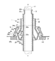
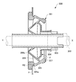
- FIG. 1 is an axial view of a wire harness according to an embodiment of the present invention.
- FIG. 2 is a cross-sectional view taken along the line AA in FIG.
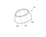
- FIG. 3 is a cross-sectional view taken along the line BB in FIG. 1 is a perspective view of a grommet applied to a wire harness according to an embodiment of the present invention. It is explanatory drawing of the principal part of the wire harness which concerns on one embodiment of this invention. It is explanatory drawing of the other principal part of the wire harness which concerns on one embodiment of this invention.
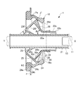
- FIG. 6 is a longitudinal sectional view of a main part of a wire harness according to another embodiment of the present invention, and corresponds to FIG. 2 which is a sectional view taken along line AA in FIG.
- FIG. 12 is a cross-sectional view taken along line EE in FIG. 11.
- FIG. 12 is a sectional view taken along line FF in FIG. 11. It is a longitudinal cross-sectional view of the grommet of a prior art example.
- the wire harness 1 As shown in FIGS. 1 to 4, the wire harness 1 according to the present embodiment is provided in an oval through hole H2 (opening) opened in a vehicle body panel P that is a partition wall between the engine room X and the vehicle compartment Y.
- a grommet 12 to be mounted, a wire group 11 inserted through the grommet 12, and a tape winding fixing portion 13 that fixes the wire group 11 to the grommet 12 are provided.
- the grommet 12 includes a first cylindrical portion 21, a second cylindrical portion 22, a pedestal portion 24, a truncated cone-shaped cylindrical portion 23, and a first pseudo truncated bun.
- a rubber molded body rubber elasticity having a conical cylindrical portion 25 and a second pseudo truncated conical cylindrical portion 26, having excellent flexibility, high tensile strength, and excellent weather resistance and durability.
- the frustoconical cylinder portion 23 and the first pseudo frustoconical cylinder portion 25 correspond to an annular connecting portion or a vehicle compartment side annular connecting portion in the present invention.
- the second pseudo truncated conical cylinder portion 26 corresponds to a base end side portion or an engine room side annular connection portion of the second cylinder portion in the present invention.
- the first tube portion 21 is formed in a cylindrical shape having a required length extending on both sides of the vehicle body panel P, and has a required inner diameter required for the wire group 11 to be inserted, for example, in a close contact state.
- the first cylinder portion 21 has a length of, for example, 20 cm, the vicinity of the central portion in the axial direction is in a position passing through the through hole H2, and both ends extend to the engine room X and the vehicle compartment Y.
- the second cylindrical portion 22 is formed in a cylindrical shape having a required large diameter and a shorter required length than the first cylindrical portion 21, and is positioned so as to coaxially surround the axial intermediate portion of the first cylindrical portion 21.
- the pedestal portion 24 has an oval planar shape, and has a step portion 24a that is slightly larger than the contour of the oval through hole H2 of the vehicle body panel P at the end on the vehicle compartment Y side, and the step portion 24a.
- the pedestal portion 24 can be passed through the portion adjacent to the stepped portion 24a across the annular groove portion 24b while forcibly reducing the diameter with respect to the inner peripheral edge Pe of the through hole H2.
- the pedestal portion 24 is formed in a long cylindrical shape having an inner diameter larger than that of the second cylindrical portion 22, and approaches the vehicle interior Y side with respect to the second cylindrical portion 22 so that the first cylindrical portion 21 is moved. It is arranged so as to surround the same axis.
- the pedestal portion 24 is attached to the inner peripheral edge Pe of the through hole H2 of the vehicle body panel P in a fitting state with a stepped portion 24a formed on the passenger compartment Y side.
- the grommet 12 is disposed on the vehicle body Y side of the vehicle body panel P so that the second cylindrical portion 22 faces the engine room X side, and the electric wire group 11 is inserted through the through hole H2 of the vehicle body panel P to thereby move the engine room X side.
- the first cylindrical portion 21 and the second cylindrical portion 22 pass through the through hole H2, and the stepped portion 24a of the pedestal portion 24 is hooked to the inner peripheral edge Pe of the through hole H2 of the vehicle body panel P.
- the frustoconical cylindrical portion 23 is integrally connected to the first cylindrical portion 21 at an axial position corresponding to the step portion 24a of the pedestal portion 24, and as shown in FIG.
- the truncated conical cylindrical portion 23 is coaxially coupled to the first cylindrical portion 21 between the pedestal portion 24 and the first cylindrical portion 21, and a small-diameter end portion 23 a thereof is the first cylindrical portion.
- the large-diameter end portion 23b is connected to the outer peripheral surface of the intermediate portion in the axial direction of the portion 21 and extends toward the passenger compartment Y side.
- the first tube portion 21 may be arranged so as to cross the axis with respect to the pedestal portion 24.
- the first pseudo frustoconical tube portion 25 is positioned between the frustoconical tube portion 23 and the pedestal portion 24, and the small-diameter end portion 25 a of the frustoconical tube portion 23.
- the large diameter end portion 25 b is integrally connected to the large diameter end portion 23 b, and the large diameter end portion 25 b is integrally connected to the middle portion of the inner peripheral surface of the pedestal portion 24.
- the first pseudo truncated conical cylinder portion 25 has a pair of first half-conical cylinder portions 25A and 25B on both sides, and a space between the pair of first half-conical cylinder portions 25A and 25B.
- the pair of first inclined surface portions 25C are integrally connected.
- the second pseudo frustoconical tube portion 26 is located between the first pseudo frustoconical tube portion 25 and the cylindrical portion 22a of the second tube portion 22, and is located at one end in the axial direction thereof.
- the large-diameter end portion 26a is integrally connected to the large-diameter end portion 25b located in the middle of the first pseudo truncated conical cylinder portion 25 near the pedestal portion 24.
- the small diameter end portion 26 b on the other axial end side of the second pseudo truncated conical cylinder portion 26 is coupled to the end portion of the cylindrical portion 22 a of the second cylinder portion 22 so as to be integrally connected.
- the second pseudo frustoconical cylinder portion 26 is inclined with respect to the axis and outer peripheral surface of the first cylinder portion 21 at a predetermined inclination angle ⁇ 2.
- the intermediate connecting portion 27 between the cylindrical portion 22a of the second cylindrical portion 22 and the small-diameter end portion 26b of the second pseudo truncated conical cylindrical portion 26 that is the proximal end portion of the second cylindrical portion 22 is a pedestal portion.
- 24 is an axially intermediate portion arranged at an axial position corresponding to the end 24d on the engine room X side.
- the second pseudo truncated conical cylindrical portion 26 extends radially from the small diameter end portion 26b toward the large diameter end portion 26a on the surface on the engine room X side, and extends in the longitudinal direction of the pedestal portion 24. It has a plurality of rib portions 28 connected to the peripheral surface.
- the plurality of rib portions 28 include an inclined annular wall portion constituted by the first pseudo frustoconical tube portion 25 and a small diameter end portion of the second pseudo frustoconical tube portion 26.
- 26b which is integrally coupled to each of the proximal end portions of the second cylindrical portion 22, and on both sides in the major axis direction of the substantially oval base 24, the second cylindrical portion 22 It extends from the intermediate connecting portion 27, which is an axially intermediate portion, toward the first pseudo frustoconical tube portion 25, and protrudes from the second tube portion 22 toward the pedestal portion 24.
- the frustoconical tube portion 23 and the first pseudo frustoconical tube portion 25 constitute a connecting portion that connects the first tube portion 21 and the pedestal portion 24, and the first pseudo wharf portion
- the truncated conical tube portion 23 located between the conical tube portion 25 and the first tube portion 21 is opposite to the annular inclined surface 25f of the first pseudo truncated conical tube portion 25 in the axial direction. It is an inclined inner frustoconical wall. Accordingly, the frustoconical cylindrical portion 23 and the first pseudo frustoconical cylindrical portion 25 form the inclined annular surfaces 23f and 25f, respectively, and the wall surfaces of the inclined annular surfaces 23f and 25f are connected to each other. It has a bent cross-sectional shape that bends.
- the second pseudo truncated conical tube portion 26 is provided between the second tube portion 22 and the first pseudo truncated conical tube portion 25 with respect to the first pseudo truncated cone tube portion 25.
- the annular inclined surface 25f is an outer frustoconical wall portion inclined in the opposite direction in the axial direction, and is arranged coaxially while being inclined in the same direction as the frustoconical tube portion 23.
- the second pseudo truncated conical tube portion 26 has a pair of second semi-conical tube portions 26A and 26B on both sides, and a pair of second semi-conical tube portions.
- the portion 26A, 26B has an integrated shape in which a pair of second inclined surface portions 26C are integrally connected.
- the tape winding fixing part 13 is a fixing part that winds and fixes an adhesive tape around the first cylinder part 21, the electric wire group 11, and the second cylinder part 22, and constitutes an annular fixing member according to the present invention.
- the second tube portion 22 is provided with a protrusion 22b and a notch portion 22c for locking the winding at the beginning of winding of the tape so that the tape winding fixing portion 13 does not come off.
- the first pseudo frustoconical shape that is coupled to the first cylindrical portion 21 and the pedestal portion 24 and supports the proximal end portion of the second cylindrical portion 22.
- the cylindrical portion 25 extends from the second cylindrical portion 22 to the pedestal portion while extending from the intermediate coupling portion 27 of the second cylindrical portion 22 to the first pseudo truncated conical cylindrical portion 25 on both sides in the major axis direction of the pedestal portion 24. Reinforced by a plurality of ribs 28 protruding to the 24 side.
- both end sides of the pedestal portion 24 in the major axis direction thus, the second pseudo truncated conical cylindrical portion 26 is effectively prevented from falling or bending and the electric wire group 11 necessary for fitting the pedestal portion 24 to the vehicle body panel P side is suppressed.
- the tensile stroke (the moving stroke in the right direction in FIG. 2), which is the tensile direction, can be suppressed to be as short as both sides of the pedestal 24 in the short diameter direction. As a result, the grommet 12 can be efficiently attached to the vehicle body panel P.
- the grommet 12 is disposed on the vehicle body Y side of the vehicle body panel P so that the second cylindrical portion 22 faces the engine room X side, and the electric wire group 11 is inserted into the through hole H2 of the vehicle body panel P.
- the first cylindrical portion 21 and the second cylindrical portion 22 pass through the through hole H2, and the stepped portion 24a of the pedestal portion 24 passes through the inner peripheral edge Pe of the through hole H2 of the vehicle body panel P.
- the intermediate outer diameter portion 24c in the vicinity of is caught.
- the intermediate outer diameter portion 24c of the pedestal portion 24 is elastically deformed in the reduced diameter direction, and the vehicle body is formed in the annular groove portion 24b formed in the step portion 24a.
- the inner peripheral edge of the through hole H2 of the panel P is fitted, and the grommet 12 is fixed to the vehicle body panel P.
- the first cylindrical portion 21 and the pedestal portion 24 are integrated with each other via the truncated conical cylindrical portion 23 and the first pseudo truncated conical cylindrical portion 25.
- the second cylinder portion 22 and the first pseudo frustoconical cylinder portion 25 are connected together via the second pseudo frustoconical cylinder portion 26, and are connected to each other.
- the connecting portion between the truncated conical tube portion 25 and the second pseudo truncated conical tube portion 26 is at a position close to the pedestal portion 24, and the first pseudo truncated cone tube portion 25 and the second simulated frustoconical tube portion 25.
- the frustoconical cylindrical portion 26 does not have a conventional flat surface parallel to a plane perpendicular to the axis of the first cylindrical portion 21, and the second pseudo frustoconical cylindrical portion 26 is provided with the engine.
- the surface of the room X side extends radially from the small-diameter end portion 26b toward the large-diameter end portion 26a in the longitudinal direction of the pedestal portion 24, and the inner periphery of the pedestal portion 24
- the first pseudo truncated cone is provided.
- the expansion of the shape cylinder part 25 and the second pseudo truncated cone-shaped cylinder part 26 is suppressed, and the force pulling the wire group 11 is efficiently transmitted to the pedestal part 24 of the grommet 12.
- the tension stroke of the electric wire group 11 necessary for fitting the inner peripheral edge Pe of the through hole H2 of the vehicle body panel P into the annular groove 24b of the base 24.
- the grommet 12 can be efficiently attached to the vehicle body panel P.
- the first pseudo truncated conical cylindrical portion 25 has a pair of first half-conical cylindrical portions 25A and 25B on both sides, and a pair of The first semi-conical truncated cylinder portions 25A and 25B have an integral shape integrally connected by a pair of first inclined surface portions 25C, and the second pseudo truncated conical cylinder portion 26 has a pair of both side portions. Since the second semi-conical cylinder portions 26A and 26B are provided and the pair of second semi-conical cylinder portions 26A and 26B are integrally formed with the pair of second inclined surface portions 26C.
- the first pseudo frustoconical tube portion 25 and the second pseudo frustoconical tube portion 26 have a geometric shape, and the mold can be easily designed and manufactured.
- the intermediate connecting portion 27 between the second cylindrical portion 22 and the second pseudo truncated conical cylindrical portion 26 is the end of the pedestal portion 24 on the engine room X side. Since the tape winding fixing part 13 is located close to the pedestal part 24, the mounting stroke of the grommet 12 to the through hole H2 of the vehicle body panel P can be kept short.
- the grommet 12 that can be efficiently mounted on the vehicle body panel P can be provided.
- the plurality of rib portions 28 are the intermediate connection portions 27 that are the intermediate portions in the axial direction of the second cylindrical portion 22 on both sides in the major diameter direction of the substantially oval base 24. From the second cylindrical portion 22 to the pedestal portion 24 side, and is connected to the pedestal portion 24 in the entire extending region. However, since it is a correction rib for transmitting the operating force in the grommet mounting direction from the second cylindrical portion 22 to the pedestal portion 24, from the connection position of the pedestal portion 24 and the first pseudo truncated conical cylindrical portion 25. A plurality of rib portions 28 do not need to be connected to the end 24d on the engine room X side of the pedestal portion 24 that is separated.
- the grommet 12 may be configured as in another embodiment shown in FIG.
- the plurality of rib portions 28 are formed from the vicinity of the intermediate connection portion 27 of the second cylindrical portion 22 (the axial intermediate portion) from the first pseudo frustoconical shape. It extends to the connecting portion j1 of the cylindrical portion 25 and the pedestal portion 24, and the protruding height of the plurality of rib portions 28 from the second cylindrical portion 22 is located on the intermediate connecting portion 27 side of the second cylindrical portion 22. It is small on one end side and is large on the other end side connected to the first pseudo truncated conical tube portion 25.
- the plurality of rib portions 28 are formed by the inclined annular wall portion constituted by the first pseudo frustoconical tube portion 25 and the small diameter end portion 26b of the second pseudo frustoconical tube portion 26.
- the plurality of rib portions 28 may be arranged at predetermined angular intervals with respect to the semiconical cylinder portion 26A or 26B located on each one side in the major axis direction of the pedestal portion 24, and with respect to the major axis direction.
- the rib width may be different, or the rib width may be different on one end side and the other end side in the extending direction.
- the ridge line on the protruding end side of the plurality of rib portions 28 extending from the vicinity of the intermediate connecting portion 27 of the second cylindrical portion 22 to the first pseudo truncated conical cylindrical portion 25 and the connecting portion j1 of the pedestal portion 24. May be a straight line or a curved line.
- the long diameter of the pedestal 24 is obtained. It is effectively suppressed that the second pseudo truncated conical cylinder portion 26 falls or bends and deforms at both ends in the direction, and is necessary for fitting the pedestal portion 24 to the vehicle body panel P side.
- the tensile stroke of the electric wire group 11 is also suppressed to be as short as both sides of the base portion 24 in the short-diameter direction, so that the grommet 12 can be efficiently attached to the vehicle body panel P.
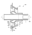
- FIGS. 8 to 10 show a first comparative example modified based on the conventional grommet 101 so that it can be mounted in the oval through hole H2.
- the wire harness 208 of this comparative example includes a grommet 201 indicated by a solid line that is passed through an oval through hole H2 opened in a vehicle body panel P that is a partition wall between the engine room X and the vehicle compartment Y, and a grommet 201 And an electric wire group 202 indicated by a two-dot chain line that is passed through and fixed.
- the grommet 201 includes a cylindrical first cylindrical portion 203, a cylindrical second cylindrical portion 204 that coaxially surrounds the axially intermediate portion of the first cylindrical portion 203, the first cylindrical portion 203, and the second cylindrical portion 203.
- the grommet 201 includes a cylindrical first cylindrical portion 203 and a second cylindrical portion 204 that are formed with respect to a pedestal portion 205 having an oval planar shape, and a first wall portion 206 and a second wall portion 207. Are connected together.
- the second wall portion 207 is formed in a trumpet shape that expands at the same rate in the radial direction toward the passenger compartment Y side with the axis of the first tube portion 203 as the center.
- the first wall portion 206 includes an intermediate coupling portion 206 d between the first wall portion 206 and the second wall portion 207, and an outer peripheral side of the first wall portion 206 and the pedestal portion 205.
- a portion between the coupling portion 206 c is formed to be a flat surface F perpendicular to the axis of the first cylindrical portion 203.
- This flat surface F is an area indicated by hatching A1 in FIG. That is, the grommet 201 has a flat surface F shown in FIG.
- the inner peripheral edge of the through hole H2 of the vehicle body panel P is formed as a short elliptical cylindrical flange that is bent on the engine room X side.
- the pedestal part 205 has an annular groove part 205a including a conical cylinder surface corresponding to the flange of the through hole H2, and the flange of the through hole H2 of the vehicle body panel P is fitted into the outer peripheral part.
- a portion protruding from the first tube portion 203 to the engine room X side and the end portions on the engine room X side of the first tube portion 203 and the second tube portion 204 are wound with an adhesive tape. It is fixed integrally by the tape winding fixing part T.
- the grommet 201 is disposed on the vehicle body Y side of the vehicle body panel P so that the second cylindrical portion 204 faces the engine room X side, and the electric wire group 202 is inserted into the through hole H2 of the vehicle body panel P.
- the first cylindrical portion 203 and the second cylindrical portion 204 pass through the through hole H2, and the outer peripheral portion of the pedestal portion 205 is caught on the inner peripheral edge portion of the through hole H2 of the panel P.
- the pedestal portion 205 is elastically deformed, and the flange of the through hole H2 of the panel P is fitted into the annular groove portion 205a of the pedestal portion 205.
- Grommet 201 is fixed to P.
- the outer periphery of the pedestal part 205 is disposed on the inner peripheral edge of the through hole H2 of the panel P.
- the portion forming the flat surface F in the first wall portion 206 extends obliquely with respect to the axis of the first cylindrical portion 203. Elastically deforms.
- the pulling stroke of the electric wire group 202 necessary for fitting the inner peripheral edge portion of the through hole H2 of the panel P into the annular groove portion 205a of the pedestal portion 205 becomes long, and the grommet 201 is attached to the vehicle body panel P. It cannot be installed efficiently.
- a grommet 301 shown in FIGS. 11 to 13 is based on the grommet 101 described above and shows a second comparative example that is mounted in an oval through hole H2.
- the grommet 301 is coaxial with the first cylindrical portion 303 through which the electric wire group 302 routed between the engine room X and the passenger compartment Y passes in close contact with the axial intermediate portion of the first cylindrical portion 303.
- a second cylindrical portion 304 that surrounds the first cylindrical portion 304, a pedestal portion 305 that coaxially surrounds the first cylindrical portion 303 and the second cylindrical portion 304 and that is mounted in the through hole H2 in the vehicle body panel P, and a first cylindrical portion
- the first intermediate portion 303 is integrally connected to the outer peripheral surface of the axial intermediate portion 303 and the inner peripheral surface of the axial intermediate portion of the pedestal portion 305, and has a cross-sectional shape that refracts in a mountain shape toward the passenger compartment Y side and extends in the circumferential direction.
- the wall portion 306 a second portion extending in the circumferential direction integrally with the portion on the radially outer side than the mountain-shaped refracting portion 306 a of the first wall portion 306 and the end portion of the second cylindrical portion 304 on the vehicle interior Y side.
- a wall portion 307, and a grommet 301 and a wire group 302 Constitute a wire harness 308 I.
- the grommet 301 has a cylindrical first cylindrical portion 303 and a second cylindrical portion 304 with respect to the pedestal portion 305 having an oval planar shape, and the first wall portion 306 and the second wall portion. They are coupled together via a portion 307.
- the second wall portion 307 forms a flat surface F in which the portion on the second cylindrical portion 304 side is orthogonal to the axis of the first cylindrical portion 303 in the oval longitudinal cross section.
- the first wall portion 306 side portion is formed in a trumpet shape that expands toward the passenger compartment Y side.
- the flat surface F is an area indicated by hatching A2 in FIG. That is, the grommet 301 has the flat surfaces F shown in FIG. 12 corresponding to the area shown by hatching A2 shown in FIG. 11 on both sides in the major axis direction, is formed in an oval planar shape, and is short as shown in FIG.
- the cross-sectional shape in the axial direction does not have a flat surface F as shown in FIG.
- the first tube portion 303 and the second tube portion 304 are formed in a cylindrical shape.
- the pedestal portion 305 has an oval planar shape, and an annular groove portion 305a into which an inner peripheral edge portion of an oval through hole H2 opened in the vehicle body panel P is fitted on the outer peripheral portion.
- a portion protruding from the first tube portion 303 to the engine room X side and an end portion on the engine room X side of the first tube portion 303 and the second tube portion 304 are wound with an adhesive tape. It is fixed integrally by the tape winding fixing part T.
- the grommet 301 is disposed on the vehicle body Y side of the vehicle body panel P so that the second cylindrical portion 304 faces the engine room X side,
- the electric wire group 302 is inserted through the through hole H2 of the vehicle body panel P and pulled toward the engine room X side, the first cylindrical portion 303 and the second cylindrical portion 304 pass through the through hole H2 and pass through the through hole H2 of the panel P.
- the outer peripheral part of the pedestal part 305 is caught on the inner peripheral edge part.
- the pedestal 305 When the wire harness 308 pulls the electric wire group 302 to the engine room X side more strongly, the pedestal 305 is elastically deformed, and the inner peripheral edge of the through hole H2 of the panel P is fitted into the annular groove 305a of the pedestal 305. Therefore, the grommet 301 is fixed to the vehicle body panel P.
- the pulling stroke of the wire group 302 required to fit the inner peripheral edge portion of the through hole H2 of the panel P into the annular groove portion 305a of the pedestal portion 305 becomes longer, and the grommet 301 is attached to the vehicle body panel P. It cannot be installed efficiently.
- the present invention has an effect that the grommet can be efficiently attached to the oval through hole opened in the vehicle body panel, and the grommet to be attached to the oval through hole of the vehicle panel is provided. It is useful for general grommets and wire harnesses.
Landscapes
- Engineering & Computer Science (AREA)
- Architecture (AREA)
- Civil Engineering (AREA)
- Structural Engineering (AREA)
- Mechanical Engineering (AREA)
- Installation Of Indoor Wiring (AREA)
- Insulating Bodies (AREA)
- Insulated Conductors (AREA)
Abstract
Description
図1~図4に示すように、本実施の形態に係るワイヤハーネス1は、エンジンルームXと車室Yとの隔壁である車体パネルPに開口された長円形の貫通孔H2(開口)に装着されるグロメット12と、グロメット12に挿通された電線群11と、グロメット12に電線群11を固定するテープ巻き固定部13とを有する。
そこで、グロメット12は、図7に示す他の実施の形態のように構成してもよい。
図8~図10は、従来例のグロメット101を基に、長円形の貫通孔H2に装着できるように変形した第1の比較例を示している。
図11~図13に示すグロメット301は、上記のグロメット101を基本とし、長円形の貫通孔H2に装着される第2の比較例を示している。
11 電線群
12 グロメット
13 テープ巻き固定部(環状の固定部材)
21 第1の筒部
22 第2の筒部
22a 車室側端部
23 截頭円錐形筒部(連結部、内側の截頭円錐面形壁部、車室側環状連結部)
23a 小径端部
23b 大径端部
24 台座部(ゴム弾性体)
24a 段部(環状凹凸形状部分)
24b 環状溝部(環状凹凸形状部分)
24c 中間外径部24c(環状凹凸形状部分)
25 第1の擬似截頭円錐形筒部(連結部、傾斜環状壁部、車室側環状連結部)
25a 小径端部
25b 大径端部
25f 環状傾斜面
25A,25B 第1の半円錐台筒部分(長径方向両側の部分)
25C 第1の傾斜面部分
26 第2の擬似截頭円錐形筒部(エンジンルーム側環状連結部)
26a 大径端部(外側の截頭円錐面形壁部)
26b 小径端部(第2の筒部の基端側部分)
26A,26B 第2の半円錐台筒部分(長径方向両側の部分)
26C 第2の傾斜面部分
27 中間連結部分(軸方向中間部分)
H2 貫通孔(開口)
P 車体パネル
Pe 内周縁部(開口の縁部、開口部)
X エンジンルーム
Y 車室
Claims (9)
- 電線群に外装されつつ車体パネルの開口を閉塞するよう前記車体パネルに装着されるグロメットであって、
前記電線群が挿通される第1の筒部と、
前記第1の筒部より短く形成され、前記第1の筒部を取り囲む第2の筒部と、
前記第2の筒部を取り囲む縮径可能な環状のゴム弾性体で構成されるとともに、前記車体パネルの前記開口の縁部に嵌合可能な環状凹凸形状部分を有する台座部と、
前記第1の筒部と前記台座部を弾性的に連結する環状の連結部と、を備え、
前記台座部が、略長円形状を有し、
前記連結部が、前記第1の筒部と前記台座部の間で前記第1の筒部の軸方向に傾斜する傾斜環状面を形成しつつ前記第2の筒部の基端部分を支持する傾斜環状壁部を有し、
前記傾斜環状壁部および前記第2の筒部には、前記略長円形状の長径方向の両側で、前記第2の筒部の軸方向中間部分から前記傾斜環状壁部に延びるとともに前記第2の筒部から前記台座部側に突出する複数のリブ部が一体に設けられていることを特徴とするグロメット。 - 前記連結部が、前記傾斜環状壁部と前記第1の筒部の間に、前記傾斜環状壁部の前記環状傾斜面とは前記軸方向で逆向きに傾斜する内側の截頭円錐面形壁部を有することを特徴とする請求項1に記載のグロメット。
- 前記第2の筒部の前記基端部分と前記連結部の前記傾斜環状壁部との間に、前記傾斜環状壁部の前記環状傾斜面とは前記軸方向で逆向きに傾斜する外側の截頭円錐面形壁部が一体に設けられていることを特徴とする請求項1または2に記載のグロメット。
- 前記複数のリブ部は、前記第2の筒部の軸方向中間部分から前記傾斜環状壁部および前記台座部の連結部分に及んでおり、
前記第2の筒部からの前記複数のリブ部の突出高さが、前記第2の筒部の軸方向中間部分側に位置する一端側で小さく、前記傾斜環状壁部に連結する他端側で大きくなっていることを特徴とする請求項1ないし3のいずれか1項に記載のグロメット。 - 電線群が挿通される第1の筒部を有し、エンジンルームと車室との隔壁である車体パネルに開口された長円形の貫通孔に装着されるグロメットであって、
前記第1の筒部よりも所要大径で所要短い円筒状に形成され、かつ前記第1の筒部の軸方向中間部を同軸に取り囲むように位置される第2の筒部と、
前記第2の筒部よりも所要大きい長円筒形に形成され、かつ前記第2の筒部に対して車室側に寄って前記第1の筒部を同軸に取り囲むように位置され、かつ車室側に形成された段部で前記車体パネルの前記貫通孔に装着される台座部と、
大径端部が前記台座部の内周面に一体に連なりかつ小径端部が前記第1の筒部の外周面に一体に連なる車室側環状連結部と、
大径端部が前記車室側環状連結部の大径端部寄りの中途部に一体に連なりかつ小径端部が前記第2の筒部の車室側端部に一体に連なるエンジンルーム側環状連結部と、を有し、
前記台座部は、長円形の平面形状を有し、かつ外周部に前記貫通孔の開口縁部が嵌まり込む環状溝部を有し、
前記エンジンルーム側環状連結部は、小径端部から大径端部に向けて前記台座部の長手方向に放射状に延び、かつ前記台座部の内周面に一体に連なる複数条のリブ部をエンジンルーム側に有することを特徴とするグロメット。 - 前記車室側環状連結部は、
前記台座部の前記段部に対応するように位置され、小径端部が前記第1の筒部の軸方向中間部外周面に一体に連なりかつ大径端部が車室側に延びている截頭円錐形筒部と、
前記截頭円錐形筒部と前記台座部の間に位置され、小径端部が前記截頭円錐形筒部の大径端部に一体に連なりかつ大径端部が前記台座部の内周面中途部に一体に連なる第1の擬似截頭円錐形筒部と、を有し、
前記エンジンルーム側環状連結部は、前記第1の擬似截頭円錐形筒部と第2の筒部との間に位置され、大径端部が前記第1の擬似截頭円錐形筒部の大径端部寄りの中途部に一体に連なりかつ小径端部が前記第2の筒部の車室側端部に一体に連なる第2の擬似截頭円錐形筒部を有していることを特徴とする請求項5に記載のグロメット。 - 前記第1の擬似截頭円錐形筒部は、両側部分が一対の第1の半円錐台筒部分を有し、かつ前記一対の第1の半円錐台筒部分の間が一対の第1の傾斜面部分で一体に連なる一体形状であり、
前記第2の擬似截頭円錐形筒部は、両側部分が一対の第2の半円錐台筒部分を有し、かつ前記一対の第2の半円錐台筒部分の間が一対の第2の傾斜面部分で一体に連なる一体形状であることを特徴とする請求項6に記載のグロメット。 - 前記第2の筒部と前記第2の擬似截頭円錐形筒部との連結部が、前記台座部のエンジンルーム側の端部に対応する内方に位置されていることを特徴とする請求項6に記載のグロメット。
- 請求項1ないし4のいずれか1項に記載のグロメットと、
前記グロメットの前記第1の筒部に挿通された前記電線群と、
前記第1の筒部の一端側に位置する前記グロメットの前記第2の筒部の先端部分を前記第1の筒部の周囲に固定するとともに、前記第1の筒部の一端側の部分を前記電線群に固定する環状の固定部材と、を備えたワイヤハーネス。
Priority Applications (3)
| Application Number | Priority Date | Filing Date | Title |
|---|---|---|---|
| CN201680018958.0A CN107408431B (zh) | 2015-04-07 | 2016-04-05 | 护线套及线束 |
| US15/563,869 US10192657B2 (en) | 2015-04-07 | 2016-04-05 | Grommet and wire harness |
| JP2017510989A JP6350743B2 (ja) | 2015-04-07 | 2016-04-05 | グロメットおよびワイヤハーネス |
Applications Claiming Priority (2)
| Application Number | Priority Date | Filing Date | Title |
|---|---|---|---|
| JP2015-078566 | 2015-04-07 | ||
| JP2015078566 | 2015-04-07 |
Publications (1)
| Publication Number | Publication Date |
|---|---|
| WO2016163358A1 true WO2016163358A1 (ja) | 2016-10-13 |
Family
ID=57072607
Family Applications (1)
| Application Number | Title | Priority Date | Filing Date |
|---|---|---|---|
| PCT/JP2016/061128 Ceased WO2016163358A1 (ja) | 2015-04-07 | 2016-04-05 | グロメットおよびワイヤハーネス |
Country Status (4)
| Country | Link |
|---|---|
| US (1) | US10192657B2 (ja) |
| JP (1) | JP6350743B2 (ja) |
| CN (1) | CN107408431B (ja) |
| WO (1) | WO2016163358A1 (ja) |
Families Citing this family (11)
| Publication number | Priority date | Publication date | Assignee | Title |
|---|---|---|---|---|
| JP2017169424A (ja) * | 2016-03-18 | 2017-09-21 | 住友電装株式会社 | グロメット |
| JP6685497B2 (ja) * | 2016-06-14 | 2020-04-22 | 矢崎総業株式会社 | ワイヤハーネス |
| JP6789109B2 (ja) * | 2016-12-28 | 2020-11-25 | 富士フイルム株式会社 | 血液分析方法及び血液検査キット |
| CN107769122A (zh) * | 2017-12-19 | 2018-03-06 | 宁波诗宏千禧贸易有限公司 | 用于汽车线束的橡胶护套 |
| CN109050442B (zh) * | 2018-08-15 | 2021-07-06 | 安徽奥丰汽车配件有限公司 | 一种汽车橡胶过线防尘护套 |
| JP6860535B2 (ja) * | 2018-09-10 | 2021-04-14 | 矢崎総業株式会社 | グロメット |
| US20210359500A1 (en) * | 2018-10-02 | 2021-11-18 | Nidal Qumsieh | Sealing apparatus |
| JP7256466B2 (ja) * | 2019-10-30 | 2023-04-12 | 住友電装株式会社 | グロメット |
| JP7117337B2 (ja) * | 2020-02-03 | 2022-08-12 | 矢崎総業株式会社 | グロメット、及び、ワイヤハーネス |
| JP7159235B2 (ja) * | 2020-02-17 | 2022-10-24 | 矢崎総業株式会社 | グロメット及びワイヤハーネス |
| DE102021118919A1 (de) * | 2020-09-23 | 2022-03-24 | Illinois Tool Works Inc. | Tüllenvorrichtung |
Citations (3)
| Publication number | Priority date | Publication date | Assignee | Title |
|---|---|---|---|---|
| JP2009296739A (ja) * | 2008-06-03 | 2009-12-17 | Sumitomo Wiring Syst Ltd | グロメット |
| JP2011217552A (ja) * | 2010-04-01 | 2011-10-27 | Sumitomo Wiring Syst Ltd | ワイヤハーネス用のグロメット |
| JP2012100396A (ja) * | 2010-10-29 | 2012-05-24 | Sumitomo Wiring Syst Ltd | ワイヤハーネス用のグロメット |
Family Cites Families (6)
| Publication number | Priority date | Publication date | Assignee | Title |
|---|---|---|---|---|
| JP3570660B2 (ja) * | 1997-08-08 | 2004-09-29 | 矢崎総業株式会社 | グロメット |
| JP5266670B2 (ja) * | 2007-06-13 | 2013-08-21 | 住友電装株式会社 | グロメット |
| JP5098718B2 (ja) * | 2008-03-13 | 2012-12-12 | 住友電装株式会社 | グロメット |
| JP5530215B2 (ja) * | 2010-02-19 | 2014-06-25 | 矢崎総業株式会社 | グロメット |
| JP5408043B2 (ja) * | 2010-06-07 | 2014-02-05 | 住友電装株式会社 | グロメット |
| JP5891961B2 (ja) * | 2012-06-11 | 2016-03-23 | 住友電装株式会社 | グロメット及びグロメット付ワイヤーハーネス |
-
2016
- 2016-04-05 WO PCT/JP2016/061128 patent/WO2016163358A1/ja not_active Ceased
- 2016-04-05 US US15/563,869 patent/US10192657B2/en active Active
- 2016-04-05 CN CN201680018958.0A patent/CN107408431B/zh not_active Expired - Fee Related
- 2016-04-05 JP JP2017510989A patent/JP6350743B2/ja not_active Expired - Fee Related
Patent Citations (3)
| Publication number | Priority date | Publication date | Assignee | Title |
|---|---|---|---|---|
| JP2009296739A (ja) * | 2008-06-03 | 2009-12-17 | Sumitomo Wiring Syst Ltd | グロメット |
| JP2011217552A (ja) * | 2010-04-01 | 2011-10-27 | Sumitomo Wiring Syst Ltd | ワイヤハーネス用のグロメット |
| JP2012100396A (ja) * | 2010-10-29 | 2012-05-24 | Sumitomo Wiring Syst Ltd | ワイヤハーネス用のグロメット |
Also Published As
| Publication number | Publication date |
|---|---|
| JPWO2016163358A1 (ja) | 2017-10-05 |
| CN107408431A (zh) | 2017-11-28 |
| US20180261360A1 (en) | 2018-09-13 |
| JP6350743B2 (ja) | 2018-07-04 |
| CN107408431B (zh) | 2019-04-02 |
| US10192657B2 (en) | 2019-01-29 |
Similar Documents
| Publication | Publication Date | Title |
|---|---|---|
| JP6350743B2 (ja) | グロメットおよびワイヤハーネス | |
| KR101335197B1 (ko) | 와이어 하네스용 그로밋 | |
| US10243335B2 (en) | Water-proofing member | |
| JP2017169424A (ja) | グロメット | |
| JP2012239353A (ja) | グロメット | |
| CN111546877B (zh) | 用于将排气设备部件连接至车身的紧固装置 | |
| JP2011188619A (ja) | ワイヤハーネス用のグロメット | |
| WO2017126351A1 (ja) | グロメット | |
| JP6979910B2 (ja) | グロメット及びグロメット付ワイヤーハーネス | |
| WO2017126350A1 (ja) | グロメット | |
| JP5453166B2 (ja) | グロメット | |
| WO2016158594A1 (ja) | グロメットおよびワイヤハーネス | |
| JP2019209854A (ja) | グロメット | |
| JP7077347B2 (ja) | グロメット及びワイヤハーネス | |
| JP2018196305A (ja) | グロメット | |
| JP7335843B2 (ja) | グロメット、電線取付構造体、及び電線固定方法 | |
| JP6815721B2 (ja) | グロメット | |
| JP7151584B2 (ja) | グロメット | |
| JP6075235B2 (ja) | グロメット | |
| JP2024110623A (ja) | クランプ及びワイヤハーネス | |
| JP2015204737A (ja) | グロメット | |
| JP2020145813A (ja) | グロメット |
Legal Events
| Date | Code | Title | Description |
|---|---|---|---|
| 121 | Ep: the epo has been informed by wipo that ep was designated in this application |
Ref document number: 16776524 Country of ref document: EP Kind code of ref document: A1 |
|
| ENP | Entry into the national phase |
Ref document number: 2017510989 Country of ref document: JP Kind code of ref document: A |
|
| WWE | Wipo information: entry into national phase |
Ref document number: 15563869 Country of ref document: US |
|
| NENP | Non-entry into the national phase |
Ref country code: DE |
|
| 122 | Ep: pct application non-entry in european phase |
Ref document number: 16776524 Country of ref document: EP Kind code of ref document: A1 |