WO2016159129A1 - ラバーシート及びサスペンション装置 - Google Patents
ラバーシート及びサスペンション装置 Download PDFInfo
- Publication number
- WO2016159129A1 WO2016159129A1 PCT/JP2016/060476 JP2016060476W WO2016159129A1 WO 2016159129 A1 WO2016159129 A1 WO 2016159129A1 JP 2016060476 W JP2016060476 W JP 2016060476W WO 2016159129 A1 WO2016159129 A1 WO 2016159129A1
- Authority
- WO
- WIPO (PCT)
- Prior art keywords
- rubber sheet
- coil spring
- main body
- spring guide
- spring
- Prior art date
- Legal status (The legal status is an assumption and is not a legal conclusion. Google has not performed a legal analysis and makes no representation as to the accuracy of the status listed.)
- Ceased
Links
Images




Classifications
-
- B—PERFORMING OPERATIONS; TRANSPORTING
- B60—VEHICLES IN GENERAL
- B60G—VEHICLE SUSPENSION ARRANGEMENTS
- B60G15/00—Resilient suspensions characterised by arrangement, location or type of combined spring and vibration damper, e.g. telescopic type
- B60G15/02—Resilient suspensions characterised by arrangement, location or type of combined spring and vibration damper, e.g. telescopic type having mechanical spring
- B60G15/06—Resilient suspensions characterised by arrangement, location or type of combined spring and vibration damper, e.g. telescopic type having mechanical spring and fluid damper
- B60G15/062—Resilient suspensions characterised by arrangement, location or type of combined spring and vibration damper, e.g. telescopic type having mechanical spring and fluid damper the spring being arranged around the damper
- B60G15/063—Resilient suspensions characterised by arrangement, location or type of combined spring and vibration damper, e.g. telescopic type having mechanical spring and fluid damper the spring being arranged around the damper characterised by the mounting of the spring on the damper
-
- B—PERFORMING OPERATIONS; TRANSPORTING
- B60—VEHICLES IN GENERAL
- B60G—VEHICLE SUSPENSION ARRANGEMENTS
- B60G11/00—Resilient suspensions characterised by arrangement, location or kind of springs
- B60G11/14—Resilient suspensions characterised by arrangement, location or kind of springs having helical, spiral or coil springs only
- B60G11/16—Resilient suspensions characterised by arrangement, location or kind of springs having helical, spiral or coil springs only characterised by means specially adapted for attaching the spring to axle or sprung part of the vehicle
-
- B—PERFORMING OPERATIONS; TRANSPORTING
- B60—VEHICLES IN GENERAL
- B60G—VEHICLE SUSPENSION ARRANGEMENTS
- B60G15/00—Resilient suspensions characterised by arrangement, location or type of combined spring and vibration damper, e.g. telescopic type
- B60G15/02—Resilient suspensions characterised by arrangement, location or type of combined spring and vibration damper, e.g. telescopic type having mechanical spring
- B60G15/06—Resilient suspensions characterised by arrangement, location or type of combined spring and vibration damper, e.g. telescopic type having mechanical spring and fluid damper
-
- F—MECHANICAL ENGINEERING; LIGHTING; HEATING; WEAPONS; BLASTING
- F16—ENGINEERING ELEMENTS AND UNITS; GENERAL MEASURES FOR PRODUCING AND MAINTAINING EFFECTIVE FUNCTIONING OF MACHINES OR INSTALLATIONS; THERMAL INSULATION IN GENERAL
- F16F—SPRINGS; SHOCK-ABSORBERS; MEANS FOR DAMPING VIBRATION
- F16F1/00—Springs
- F16F1/02—Springs made of steel or other material having low internal friction; Wound, torsion, leaf, cup, ring or the like springs, the material of the spring not being relevant
- F16F1/04—Wound springs
- F16F1/12—Attachments or mountings
-
- F—MECHANICAL ENGINEERING; LIGHTING; HEATING; WEAPONS; BLASTING
- F16—ENGINEERING ELEMENTS AND UNITS; GENERAL MEASURES FOR PRODUCING AND MAINTAINING EFFECTIVE FUNCTIONING OF MACHINES OR INSTALLATIONS; THERMAL INSULATION IN GENERAL
- F16F—SPRINGS; SHOCK-ABSORBERS; MEANS FOR DAMPING VIBRATION
- F16F1/00—Springs
- F16F1/02—Springs made of steel or other material having low internal friction; Wound, torsion, leaf, cup, ring or the like springs, the material of the spring not being relevant
- F16F1/04—Wound springs
- F16F1/12—Attachments or mountings
- F16F1/126—Attachments or mountings comprising an element between the end coil of the spring and the support proper, e.g. an elastomeric annulus
-
- F—MECHANICAL ENGINEERING; LIGHTING; HEATING; WEAPONS; BLASTING
- F16—ENGINEERING ELEMENTS AND UNITS; GENERAL MEASURES FOR PRODUCING AND MAINTAINING EFFECTIVE FUNCTIONING OF MACHINES OR INSTALLATIONS; THERMAL INSULATION IN GENERAL
- F16F—SPRINGS; SHOCK-ABSORBERS; MEANS FOR DAMPING VIBRATION
- F16F9/00—Springs, vibration-dampers, shock-absorbers, or similarly-constructed movement-dampers using a fluid or the equivalent as damping medium
- F16F9/32—Details
-
- F—MECHANICAL ENGINEERING; LIGHTING; HEATING; WEAPONS; BLASTING
- F16—ENGINEERING ELEMENTS AND UNITS; GENERAL MEASURES FOR PRODUCING AND MAINTAINING EFFECTIVE FUNCTIONING OF MACHINES OR INSTALLATIONS; THERMAL INSULATION IN GENERAL
- F16F—SPRINGS; SHOCK-ABSORBERS; MEANS FOR DAMPING VIBRATION
- F16F9/00—Springs, vibration-dampers, shock-absorbers, or similarly-constructed movement-dampers using a fluid or the equivalent as damping medium
- F16F9/32—Details
- F16F9/36—Special sealings, including sealings or guides for piston-rods
-
- B—PERFORMING OPERATIONS; TRANSPORTING
- B60—VEHICLES IN GENERAL
- B60G—VEHICLE SUSPENSION ARRANGEMENTS
- B60G2202/00—Indexing codes relating to the type of spring, damper or actuator
- B60G2202/30—Spring/Damper and/or actuator Units
- B60G2202/31—Spring/Damper and/or actuator Units with the spring arranged around the damper, e.g. MacPherson strut
- B60G2202/312—The spring being a wound spring
-
- B—PERFORMING OPERATIONS; TRANSPORTING
- B60—VEHICLES IN GENERAL
- B60G—VEHICLE SUSPENSION ARRANGEMENTS
- B60G2204/00—Indexing codes related to suspensions per se or to auxiliary parts
- B60G2204/10—Mounting of suspension elements
- B60G2204/12—Mounting of springs or dampers
- B60G2204/124—Mounting of coil springs
- B60G2204/1242—Mounting of coil springs on a damper, e.g. MacPerson strut
Definitions
- the present invention relates to a rubber seat and a suspension device.
- JP2012-211985A includes a coil spring that is externally mounted on a shock absorber, a spring receiving member that supports the lower end portion of the coil spring and is fixed to a middle portion of the shock absorber, and a lower end portion of the spring receiving member and the coil spring. And a spring rubber seat interposed therebetween.
- a protrusion is formed on the radially inner portion of the spring receiving member.
- a deformation restricting portion formed on the spring rubber sheet is in contact with the upper end portion of the protruding portion.
- the deformation restricting portion is formed at a position corresponding to the uppermost portion of the lower end portion of the coil spring that contacts the seating portion.
- the lower end portion of the coil spring presses the upper surface portion of the seating portion of the spring rubber seat, so that the fitting portion of the spring rubber seat is radially displaced due to the compression of the seating portion. Stress that causes the outer surface to bend and deform acts. At this time, the lower part of the deformation restricting portion and the upper end surface of the protruding portion of the spring receiving member are in contact with each other.
- This invention is made in view of such a technical subject, and it aims at providing the rubber sheet which can support a coil spring stably.
- the rubber seat includes a main body portion formed in an arc shape or an annular shape, a seat portion formed in a groove shape in the main body portion and seated by the coil spring, and a terminal end of the coil spring in the main body portion. And a deformation restricting portion that is formed so as to protrude radially outward from the outer periphery of the main body portion at a position where the portion is seated.
- FIG. 1 is a partial cross-sectional view of a suspension device according to an embodiment of the present invention.
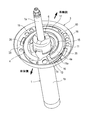
- FIG. 2 is a partial perspective view of the suspension device according to the embodiment of the present invention.
- FIG. 3 is a perspective view of the spring guide according to the embodiment of the present invention.
- FIG. 4 is a plan view of the spring guide according to the embodiment of the present invention.
- FIG. 5 is a diagram showing a change in the depth of the seating surface of the spring guide according to the embodiment of the present invention.
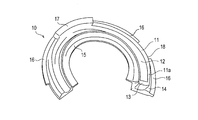
- FIG. 6 is a perspective view of a rubber sheet according to the embodiment of the present invention.
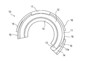
- FIG. 7 is a plan view of the rubber sheet according to the embodiment of the present invention.
- FIG. 8 is a view showing a state in which the rubber sheet according to the embodiment of the present invention is attached to the spring guide.
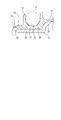
- FIG. 9 is a partial cross-sectional view taken along the line II of FIG.
- Suspension device 100 is attached to an automobile (not shown), positions wheels (not shown) and generates a damping force to absorb impacts and vibrations received from the road surface while the vehicle travels, thereby stabilizing the vehicle body. It is a suspended device.
- the suspension device 100 is attached to an outer peripheral surface of a strut type shock absorber 1 provided between a vehicle body and a wheel, an upper mount 2 attached to a tip of a piston rod 1a of the shock absorber 1, and a cylinder 1b of the shock absorber 1.
- a bump cap 6 as a cap member fitted to the end on the piston rod 1a side and a dust boot 7 as a cylindrical cover member for protecting the piston rod 1a are provided.
- a bracket 1c for connecting a hub carrier (not shown) for holding the wheel and the shock absorber 1 is provided at the end of the cylinder 1b opposite to the piston rod 1a.
- the shock absorber 1 is connected to the vehicle body by the upper mount 2 and is connected to the hub carrier by the bracket 1c and assembled to the vehicle.
- the shock absorber 1 configured in this way is configured to generate a damping force when the piston rod 1a moves in the axial direction (vertical direction in FIG. 1) with respect to the cylinder 1b.
- the suspension device 100 quickly attenuates the vibration of the vehicle body by the damping force of the shock absorber 1.
- the coil spring 4 is sandwiched between the upper mount 2 and the spring guide 3 in a compressed state, and biases the shock absorber 1 in the extending direction.
- An upper rubber sheet 8 is provided between the upper mount 2 and the coil spring 4.
- An arc-shaped rubber sheet 10 is provided between the spring guide 3 and the coil spring 4. Thereby, the spring guide 3 and the coil spring 4 do not contact directly.
- the spring guide 3 is a metal dish-like member that is fixed to the outer periphery of the cylinder 1b to support the coil spring 4.
- the spring guide 3 includes an opening 30 for inserting the cylinder 1 b, a protrusion 31 that protrudes toward the upper mount 2 and is formed so as to surround the opening 30, and a rubber sheet 10 that is formed so as to surround the protrusion 31.
- An annular mounting portion 32 having a circular arc groove 38 into which the mounting portion 32 is fitted, an annular outer edge portion 33 formed on the radially outer side of the mounting portion 32, and extending from the outer edge portion 33 toward the upper mount 2 side, And an annular support wall 34 formed so as to surround the portion 33.
- the opening 30 is formed to be eccentric from the center of the spring guide 3 toward the vehicle body.
- the spring guide 3 is fixed to the outer periphery of the cylinder 1b by welding and fixing the opening 30 to the outer periphery of the cylinder 1b.
- the opening 30 is provided with a plurality of notches 30a.
- the notch 30a functions as a drain when water or the like accumulates in the spring guide 3.
- the protruding portion 31 is formed so as to protrude to the upper mount 2 side (the upper side in FIG. 1).
- the protruding portion 31 is formed in an arc shape so that both ends in the circumferential direction are located on the vehicle body side.
- the mounting portion 32 is formed in an annular shape so as to be recessed with respect to the outer edge portion 33.
- the attachment portion 32 includes an arc groove 38 into which the rubber sheet 10 is fitted.
- the arc groove 38 is formed as an arc-shaped groove between the protruding portion 31 and the outer edge portion 33. As shown in FIGS. 4 and 5, the arc groove 38 is deepest in the vicinity of the center of the arc (b position) where the groove depth is located on the wheel side. And c), the depth of the groove becomes shallower.
- a plurality of engagement holes 39 are formed in the arc groove 38.
- a protrusion (not shown) formed on the bottom surface of the rubber sheet 10 is engaged with the engagement hole 39.
- the protrusion of the rubber sheet 10 and the engagement hole 39 engage with each other, thereby preventing the rubber sheet 10 from being displaced with respect to the spring guide 3.
- the arc groove 38 further includes two first locking pieces 35 and a second locking piece 36 that are formed upright on the outer periphery.
- Each of the two first locking pieces 35 is formed at a position facing the vicinity of the circumferential end of the rubber sheet 10 in a state where the arc-shaped rubber sheet 10 is fitted in the arc groove 38.
- the second locking piece 36 is formed at a position facing the vicinity of the central portion in the circumferential direction of the rubber sheet 10 in a state where the arc-shaped rubber sheet 10 is fitted in the arc groove 38.
- a plurality of through holes 37 are formed in the protruding portion 31, the mounting portion 32, and the outer edge portion 33.
- the through-hole 37 functions as a drain for reducing the weight, and also functions as a drain hole when water or the like accumulates in the spring guide 3.
- the rubber sheet 10 is formed of an elastic material such as rubber.
- the rubber sheet 10 is formed in an arc shape and is fitted into the arc groove 38 of the spring guide 3, an arc seating portion 12 in which the coil spring 4 is seated and formed in a groove shape in the body portion 11, and the main body A stopper portion 13 which is formed at one end in the circumferential direction of the portion 11 and abuts against the end face of the end portion 4a of the coil spring 4 to restrict the movement of the coil spring 4, and a main body portion 11 which supports the end portion 4a of the coil spring 4.
- the end portion 11a includes a deformation restricting portion 14 formed so as to protrude radially outward from the outer periphery of the main body portion 11.
- the seating portion 12 is formed to be curved so that its cross section conforms to the cross sectional shape of the coil spring 4.
- the main body portion 11 is fitted in the arc groove 38 of the spring guide 3 in a portion where the deformation restriction portion 14 is not formed, and the main body portion 11 and the deformation are formed in a portion where the deformation restriction portion 14 is formed.
- the restricting portion 14 is fitted into the arc groove 38 of the spring guide 3.
- the main body portion 11 and the deformation restricting portion 14 of the rubber sheet 10 come into contact with the bottom surface of the arc groove 38. Note that only the main body portion 11 may be fitted into the arc groove 38 and the deformation restricting portion 14 may be brought into contact with the outer edge portion 33 without being fitted into the arc groove 38.
- the rubber sheet 10 further includes an inner peripheral lip 15 and an outer peripheral lip 16 on the inner periphery and the outer periphery.
- the inner peripheral lip 15 is formed so as to protrude radially inward from the inner peripheral side surface of the main body 11.
- the outer peripheral lip 16 is formed so as to protrude from the outer peripheral side surface of the main body 11 and the outer periphery of the deformation restricting portion 14. In a state where the rubber sheet 10 is fitted in the arc groove 38 of the spring guide 3, the inner peripheral lip 15 comes into contact with the projection 31 and the outer lip 16 comes into contact with the outer edge 33. (See FIG. 9).
- the inner peripheral lip 15 and the outer peripheral lip 16 are respectively connected to the spring guide 3. Since the abutting portion 31 and the outer edge portion 33 are in contact with each other, foreign matter and the like can be prevented from entering between the main body portion 11 of the rubber sheet 10 and the arc groove 38 of the spring guide 3.
- the inner peripheral lip 15 and the outer peripheral lip 16 are pressed against the protruding portion 31 and the outer edge 33 by forming the inner peripheral lip 15 and the outer peripheral lip 16 to be inclined toward the protruding portion 31 and the outer edge 33. And abut.
- a cutout 18 is formed in the outer peripheral lip 16 at a position facing the first locking piece 35 of the spring guide 3. Further, the outer peripheral lip 16 is integrally formed with the outer peripheral lip 16 at a position facing the second locking piece 36 of the spring guide 3 so as to cover the second locking piece 36. .
- cover portion 17 foreign matter or the like can be prevented from entering between the main body portion 11 of the rubber sheet 10 and the arc groove 38 of the spring guide 3 through the second locking piece 36.
- a cover portion that covers the first locking piece 35 may be provided at a position facing the first locking piece 35 of the outer peripheral lip 16.
- a projection (not shown) formed on the surface that contacts the arc groove 38 is engaged with the engagement hole 39 of the spring guide 3, and each of the notch 18 and the cover portion 17 is the first of the spring guide 3.
- the spring guide 3 is positioned and fitted into the arc groove 38.
- a larger load acts on the wheel side than on the vehicle body side.
- a large load acts locally on the end portion 11a of the rubber sheet 10 that supports the end portion 4a of the coil spring 4 and the spring guide 3. End up.
- the end portion 4a is disposed at a position away from the wheel side (inside the vehicle body) so that the portion other than the end portion 4a of the coil spring 4 receives a large load as described above ( (See FIG. 2).
- the shock absorber 1 and the coil spring 4 of the suspension device 100 expand and contract as the wheel moves up and down.
- a large load acts on the end portion 4a of the coil spring 4 outward in the radial direction.
- stress is applied to the end portion 11 a of the rubber sheet 10 so as to deform the rubber sheet 10 so as to be twisted radially outward.
- the deformation restricting portion 14 is formed so as to protrude radially outward from the outer periphery of the main body portion 11 and is in contact with the arc groove 38 of the spring guide 3.
- transformation control part 14 controls that the main-body part 11 of the rubber sheet 10 deform
- the spring guide 3 is formed such that the opening 30 is eccentric from the center of the spring guide 3 toward the vehicle body. Further, as shown in FIG. 1, the spring guide 3 is attached so that the vehicle body side is lower than the wheel side, so it is necessary to provide a notch 30a for draining the vehicle body side. For this reason, in the spring guide 3, it is difficult to secure the radial width of the mounting portion 32 on the vehicle body side, and it is not easy to increase the depth of the circular arc groove 38 on the vehicle body side. Further, as described above, since the end portion 4a of the coil spring 4 is disposed on the vehicle body side (inside the vehicle body), the end portion 4a of the coil spring 4 is in a state where the rubber sheet 10 is fitted in the arc groove 38.
- the end 11a in the circumferential direction of the rubber sheet 10 that supports the rubber sheet 10 is positioned in the vicinity of the end (position c in FIG. 4) where the depth of the arc groove 38 of the spring guide 3 becomes shallow.
- the end portion 11a of the rubber sheet 10 when the end portion 11a of the rubber sheet 10 is positioned at a position where the depth of the arc groove 38 is shallow, the end portion 11a of the rubber sheet 10 cannot be supported by the side wall of the arc groove 38, and the end portion 11a It becomes easy to deform
- the rubber sheet 10 is formed so that the deformation restricting portion 14 projects radially outward from the outer periphery of the main body portion 11 and abuts on the arc groove 38 of the spring guide 3.
- the main body 11 of the rubber sheet 10 is restricted from being deformed so as to be twisted radially outward against the load.
- the rubber sheet 10 is provided with a deformation restricting portion 14 formed so as to protrude radially outward from the outer periphery of the main body portion 11 at the end portion 11a of the main body portion 11. Therefore, even when a large load is applied to the end portion 4a of the coil spring 4 when the coil spring 4 is contracted, the end portion 11a of the rubber sheet 10 is deformed so as to be twisted radially outward by the deformation restricting portion 14. Is regulated. Thereby, there is no possibility that the coil spring 4 will come off from the rubber sheet 10, and the coil spring 4 can be stably supported by the rubber sheet 10.
- the rubber sheet 10 has an end portion 11 a in the circumferential direction positioned at an end portion (c position) where the depth of the arc groove 38 of the spring guide 3 becomes shallow, and the deformation restricting portion 14 contacts the arc groove 38.
- the arc groove 38 is fitted so as to contact.
- the end part 11a of the rubber sheet 10 is positioned at the end part where the depth of the arc groove 38 becomes shallow. In such a configuration, when receiving a load from the end portion 4 a of the coil spring 4, the end portion of the rubber sheet 10 is easily detached from the arc groove 38.
- the deformation restricting portion 14 of the rubber sheet 10 contacts the arc groove 38 of the spring guide 3 and a frictional resistance is generated between them, so that the end portion 11a of the rubber sheet 10 is displaced and the arc groove The separation from 38 can be prevented.
- the deformation restricting portion 14 is formed so as to be in contact with the spring guide 3.
- the rubber sheet 10 has an arc shape, and is characterized in that a deformation restricting portion 14 is formed at an end portion 11a in the circumferential direction.
- the rubber sheet 10 has an arc shape, and the deformation restricting portion 14 is formed at the end 11a in the circumferential direction. Since the rubber sheet 10 has an arc shape, the end portion 11a is easily deformed. Even with such a configuration, since the deformation restricting portion 14 is formed at the circumferential end portion 11a of the rubber sheet 10, deformation of the rubber sheet 10 can be effectively restricted.
- the rubber sheet 10 is formed so as to protrude in the radial direction from the inner peripheral surface and the outer peripheral side surface of the main body 11, and is in contact with the spring guide 3 to be interposed between the main body 11 and the spring guide 3. It further comprises lips (inner peripheral lip 15 and outer peripheral lip 16) for preventing foreign substances from entering.
- the suspension device 100 includes a rubber seat 10, a shock absorber 1 provided between the vehicle body and the wheel, an upper mount 2 attached to the tip of the rod (piston rod 1 a) of the shock absorber 1, and the shock absorber 1.
- a spring guide 3 attached to the outer peripheral surface, and a coil spring 4 provided between the upper mount 2 and the spring guide 3 are provided.
- the rubber sheet 10 can be applied to the suspension device 100.
- end portion 4a of the coil spring 4 is characterized by being located inside the vehicle body.
- the end portion 4a of the coil spring 4 is located farthest from the wheel side on which the load acts. Therefore, the load acting on the end portion 11a of the rubber sheet 10 via the end portion 4a of the coil spring 4 can be reduced.
- the spring guide 3 is formed with an arc groove 38 whose depth decreases toward the end in the circumferential direction, and the rubber sheet 10 has an arc shape, and the end in the circumferential direction of the spring guide 3
- the coil spring 4 is located at the end of the arc groove 38 and is fitted into the arc groove 38 so that the deformation restricting portion 14 contacts the arc groove 38, and the terminal end 4 a of the coil spring 4 is the end of the rubber sheet 10. It is supported by the rubber sheet 10 so as to be positioned at 11a.
- the end 11a in the circumferential direction of the rubber sheet 10 where the end 4a of the coil spring 4 is located is located at the end where the depth of the arc groove 38 becomes shallow.
- the deformation restricting portion 14 of the rubber sheet 10 contacts the arc groove 38 of the spring guide 3 and a frictional resistance is generated between them, the end portion 11a of the rubber sheet 10 is displaced and separated from the arc groove 38. Can be prevented.
- the rubber sheet 10 may be annular.
- the deformation restricting portion 14 may be provided with a certain gap between it and the arc groove 38 as long as it can contact the arc groove 38. In this case, deformation of the rubber sheet 10 is allowed to some extent.
- the arc groove 38 may be configured as an annular groove. Further, a reinforcing material or the like may be embedded in the deformation restricting portion 14.
Landscapes
- Engineering & Computer Science (AREA)
- General Engineering & Computer Science (AREA)
- Mechanical Engineering (AREA)
- Springs (AREA)
- Fluid-Damping Devices (AREA)
Abstract
Description
Claims (7)
- 車体を弾性支持するコイルスプリングと前記コイルスプリングの下端部を支持するスプリングガイドとの間に設けられるラバーシートであって、
前記ラバーシートは、
円弧状または円環状に形成された本体部と、
前記本体部に溝状に形成され前記コイルスプリングが着座する着座部と、
前記本体部における前記コイルスプリングの末端部が着座する位置において、前記本体部の外周から径方向外側に突出するように形成され、前記本体部の変形を規制する変形規制部と、を備えるラバーシート。 - 請求項1に記載のラバーシートであって、
前記変形規制部は前記スプリングガイドに当接するように形成されるラバーシート。 - 請求項1に記載のラバーシートであって、
前記ラバーシートは、円弧形状であって、その周方向の端部に前記変形規制部が形成されるラバーシート。 - 請求項1に記載のラバーシートであって、
前記ラバーシートは、前記本体部の内周及び外周の側面からそれぞれ径方向に向かって突出するように形成され、前記スプリングガイドに当接して前記本体部と前記スプリングガイドとの間への異物の侵入を防止するリップをさらに備えるラバーシート。 - 請求項1に記載のラバーシートと、
車体と車輪との間に設けられるショックアブソーバと、
前記ショックアブソーバのロッドの先端に取り付けられるアッパーマウントと、
前記ショックアブソーバの外周面に取り付けられる前記スプリングガイドと、
前記アッパーマウントと前記スプリングガイドとの間に設けられる前記コイルスプリングと、を備えるサスペンション装置。 - 請求項5に記載のサスペンション装置であって、
前記コイルスプリングの前記末端部は、前記車体の内側に位置するサスペンション装置。 - 請求項5に記載のサスペンション装置であって、
前記スプリングガイドには、周方向の端部に向かって深さが浅くなる円弧溝が形成され、
前記ラバーシートは、円弧形状であって、その周方向の端部が前記円弧溝の端部に位置し、かつ、前記変形規制部が前記円弧溝に当接するようにして前記円弧溝に嵌合され、
前記コイルスプリングは、その末端部が前記ラバーシートの前記端部に位置するように前記ラバーシートに支持されるサスペンション装置。
Priority Applications (4)
| Application Number | Priority Date | Filing Date | Title |
|---|---|---|---|
| US15/562,413 US10532622B2 (en) | 2015-03-31 | 2016-03-30 | Suspension device |
| CA2979805A CA2979805A1 (en) | 2015-03-31 | 2016-03-30 | Rubber sheet and suspension device |
| MYPI2017703279A MY186192A (en) | 2015-03-31 | 2016-03-30 | Rubber sheet and suspension device |
| BR112017020077-5A BR112017020077A2 (ja) | 2015-03-31 | 2016-03-30 | A rubber sheet and a suspension device |
Applications Claiming Priority (2)
| Application Number | Priority Date | Filing Date | Title |
|---|---|---|---|
| JP2015-072912 | 2015-03-31 | ||
| JP2015072912A JP6463199B2 (ja) | 2015-03-31 | 2015-03-31 | ラバーシート及びサスペンション装置 |
Publications (1)
| Publication Number | Publication Date |
|---|---|
| WO2016159129A1 true WO2016159129A1 (ja) | 2016-10-06 |
Family
ID=57005797
Family Applications (1)
| Application Number | Title | Priority Date | Filing Date |
|---|---|---|---|
| PCT/JP2016/060476 Ceased WO2016159129A1 (ja) | 2015-03-31 | 2016-03-30 | ラバーシート及びサスペンション装置 |
Country Status (6)
| Country | Link |
|---|---|
| US (1) | US10532622B2 (ja) |
| JP (1) | JP6463199B2 (ja) |
| BR (1) | BR112017020077A2 (ja) |
| CA (1) | CA2979805A1 (ja) |
| MY (1) | MY186192A (ja) |
| WO (1) | WO2016159129A1 (ja) |
Families Citing this family (5)
| Publication number | Priority date | Publication date | Assignee | Title |
|---|---|---|---|---|
| JP7010733B2 (ja) * | 2018-03-09 | 2022-01-26 | 中央発條株式会社 | 懸架装置用スプリング |
| US20220213943A1 (en) * | 2019-05-21 | 2022-07-07 | Kyb Corporation | Spring guide and suspension device |
| CN113153958B (zh) * | 2020-01-07 | 2023-01-13 | 广州汽车集团股份有限公司 | 一种减振器、车辆悬架以及汽车 |
| JP7527921B2 (ja) * | 2020-10-01 | 2024-08-05 | 株式会社Subaru | サスペンション装置 |
| JPWO2022085103A1 (ja) * | 2020-10-21 | 2022-04-28 |
Citations (3)
| Publication number | Priority date | Publication date | Assignee | Title |
|---|---|---|---|---|
| JP2013185670A (ja) * | 2012-03-08 | 2013-09-19 | Showa Corp | 懸架装置 |
| JP2014181776A (ja) * | 2013-03-21 | 2014-09-29 | Kayaba Ind Co Ltd | スプリングラバーシート及びストラット型サスペンション |
| JP2014199134A (ja) * | 2013-03-12 | 2014-10-23 | 株式会社ショーワ | 弾性体シート及びサスペンション装置 |
Family Cites Families (10)
| Publication number | Priority date | Publication date | Assignee | Title |
|---|---|---|---|---|
| US3797852A (en) * | 1972-08-07 | 1974-03-19 | Chrysler Corp | Suspension system |
| DE4007488A1 (de) * | 1990-03-09 | 1991-09-12 | Fichtel & Sachs Ag | Federbein fuer fahrzeuge |
| US5421565A (en) * | 1994-08-11 | 1995-06-06 | General Motors Corporation | Suspension spring insulator |
| US6398201B1 (en) * | 1998-10-09 | 2002-06-04 | Daimlerchrysler Corporation | Vehicle shock absorber pad having a spring containment flange |
| US6079700A (en) * | 1998-10-09 | 2000-06-27 | Chrysler Corporation | Vehicle shock absorber spring seat pad having a spring--containment peripheral flange |
| JP4199010B2 (ja) * | 2003-01-09 | 2008-12-17 | 本田技研工業株式会社 | 車両用サスペンション装置 |
| JP5387606B2 (ja) | 2011-04-04 | 2014-01-15 | マツダ株式会社 | 車両のサスペンション構造 |
| JP6267564B2 (ja) * | 2014-03-28 | 2018-01-24 | Kyb株式会社 | 緩衝器 |
| JP6463200B2 (ja) * | 2015-03-31 | 2019-01-30 | Kyb株式会社 | スプリングガイド及びサスペンション装置 |
| JP6545505B2 (ja) * | 2015-03-31 | 2019-07-17 | Kyb株式会社 | サスペンション装置 |
-
2015
- 2015-03-31 JP JP2015072912A patent/JP6463199B2/ja active Active
-
2016
- 2016-03-30 WO PCT/JP2016/060476 patent/WO2016159129A1/ja not_active Ceased
- 2016-03-30 MY MYPI2017703279A patent/MY186192A/en unknown
- 2016-03-30 US US15/562,413 patent/US10532622B2/en active Active
- 2016-03-30 CA CA2979805A patent/CA2979805A1/en not_active Abandoned
- 2016-03-30 BR BR112017020077-5A patent/BR112017020077A2/ja not_active Application Discontinuation
Patent Citations (3)
| Publication number | Priority date | Publication date | Assignee | Title |
|---|---|---|---|---|
| JP2013185670A (ja) * | 2012-03-08 | 2013-09-19 | Showa Corp | 懸架装置 |
| JP2014199134A (ja) * | 2013-03-12 | 2014-10-23 | 株式会社ショーワ | 弾性体シート及びサスペンション装置 |
| JP2014181776A (ja) * | 2013-03-21 | 2014-09-29 | Kayaba Ind Co Ltd | スプリングラバーシート及びストラット型サスペンション |
Also Published As
| Publication number | Publication date |
|---|---|
| JP2016191453A (ja) | 2016-11-10 |
| MY186192A (en) | 2021-06-30 |
| CA2979805A1 (en) | 2016-10-06 |
| BR112017020077A2 (ja) | 2018-06-05 |
| US20180086166A1 (en) | 2018-03-29 |
| US10532622B2 (en) | 2020-01-14 |
| JP6463199B2 (ja) | 2019-01-30 |
Similar Documents
| Publication | Publication Date | Title |
|---|---|---|
| JP6545505B2 (ja) | サスペンション装置 | |
| JP6463200B2 (ja) | スプリングガイド及びサスペンション装置 | |
| CN105051402B (zh) | 弹簧橡胶座和烛式独立悬架 | |
| JP6463199B2 (ja) | ラバーシート及びサスペンション装置 | |
| JP5912621B2 (ja) | 懸架装置およびダストカバーの保持部材 | |
| WO2016084325A1 (ja) | ストラットマウント | |
| WO2015068730A1 (ja) | マウント装置 | |
| JP6437739B2 (ja) | サスペンション機構 | |
| US20170120708A1 (en) | Vehicle spring assembly | |
| JP2009243503A (ja) | ストラットマウント | |
| JP2004232824A (ja) | ストラットマウント | |
| JP5254181B2 (ja) | マウント用キャップ及びその取付構造 | |
| JP2013155838A (ja) | 懸架装置およびカバー部材 | |
| EP2025969B1 (en) | Fluid filled type vibration damping device and cover member therefor | |
| WO2016010163A1 (ja) | ブレーキ倍力装置 | |
| JP4303277B2 (ja) | 防振装置 | |
| JP7616942B2 (ja) | 防振装置 | |
| JP2013177935A (ja) | 懸架装置およびカバー部材 | |
| JP7157648B2 (ja) | サスペンション装置 | |
| JP2013194797A (ja) | アッパーサポート | |
| JP5912892B2 (ja) | 懸架装置 | |
| JP2025082182A (ja) | アッパサポート組立体 | |
| JP2024002537A (ja) | キャブマウント | |
| JP2014228024A (ja) | ストッパー | |
| JP6344855B2 (ja) | ストラットマウント |
Legal Events
| Date | Code | Title | Description |
|---|---|---|---|
| 121 | Ep: the epo has been informed by wipo that ep was designated in this application |
Ref document number: 16773010 Country of ref document: EP Kind code of ref document: A1 |
|
| ENP | Entry into the national phase |
Ref document number: 2979805 Country of ref document: CA |
|
| WWE | Wipo information: entry into national phase |
Ref document number: 15562413 Country of ref document: US |
|
| NENP | Non-entry into the national phase |
Ref country code: DE |
|
| REG | Reference to national code |
Ref country code: BR Ref legal event code: B01A Ref document number: 112017020077 Country of ref document: BR |
|
| 122 | Ep: pct application non-entry in european phase |
Ref document number: 16773010 Country of ref document: EP Kind code of ref document: A1 |
|
| ENP | Entry into the national phase |
Ref document number: 112017020077 Country of ref document: BR Kind code of ref document: A2 Effective date: 20170919 |