WO2016157756A1 - Egr装置 - Google Patents
Egr装置 Download PDFInfo
- Publication number
- WO2016157756A1 WO2016157756A1 PCT/JP2016/001378 JP2016001378W WO2016157756A1 WO 2016157756 A1 WO2016157756 A1 WO 2016157756A1 JP 2016001378 W JP2016001378 W JP 2016001378W WO 2016157756 A1 WO2016157756 A1 WO 2016157756A1
- Authority
- WO
- WIPO (PCT)
- Prior art keywords
- bearing
- shaft
- egr
- housing
- flow path
- Prior art date
- Legal status (The legal status is an assumption and is not a legal conclusion. Google has not performed a legal analysis and makes no representation as to the accuracy of the status listed.)
- Ceased
Links
Images


Classifications
-
- F—MECHANICAL ENGINEERING; LIGHTING; HEATING; WEAPONS; BLASTING
- F02—COMBUSTION ENGINES; HOT-GAS OR COMBUSTION-PRODUCT ENGINE PLANTS
- F02M—SUPPLYING COMBUSTION ENGINES IN GENERAL WITH COMBUSTIBLE MIXTURES OR CONSTITUENTS THEREOF
- F02M26/00—Engine-pertinent apparatus for adding exhaust gases to combustion-air, main fuel or fuel-air mixture, e.g. by exhaust gas recirculation [EGR] systems
- F02M26/65—Constructional details of EGR valves
- F02M26/66—Lift valves, e.g. poppet valves
- F02M26/67—Pintles; Spindles; Springs; Bearings; Sealings; Connections to actuators
-
- F—MECHANICAL ENGINEERING; LIGHTING; HEATING; WEAPONS; BLASTING
- F02—COMBUSTION ENGINES; HOT-GAS OR COMBUSTION-PRODUCT ENGINE PLANTS
- F02M—SUPPLYING COMBUSTION ENGINES IN GENERAL WITH COMBUSTIBLE MIXTURES OR CONSTITUENTS THEREOF
- F02M26/00—Engine-pertinent apparatus for adding exhaust gases to combustion-air, main fuel or fuel-air mixture, e.g. by exhaust gas recirculation [EGR] systems
- F02M26/52—Systems for actuating EGR valves
- F02M26/53—Systems for actuating EGR valves using electric actuators, e.g. solenoids
- F02M26/54—Rotary actuators, e.g. step motors
-
- F—MECHANICAL ENGINEERING; LIGHTING; HEATING; WEAPONS; BLASTING
- F02—COMBUSTION ENGINES; HOT-GAS OR COMBUSTION-PRODUCT ENGINE PLANTS
- F02M—SUPPLYING COMBUSTION ENGINES IN GENERAL WITH COMBUSTIBLE MIXTURES OR CONSTITUENTS THEREOF
- F02M26/00—Engine-pertinent apparatus for adding exhaust gases to combustion-air, main fuel or fuel-air mixture, e.g. by exhaust gas recirculation [EGR] systems
- F02M26/52—Systems for actuating EGR valves
- F02M26/55—Systems for actuating EGR valves using vacuum actuators
- F02M26/58—Constructional details of the actuator; Mounting thereof
-
- F—MECHANICAL ENGINEERING; LIGHTING; HEATING; WEAPONS; BLASTING
- F02—COMBUSTION ENGINES; HOT-GAS OR COMBUSTION-PRODUCT ENGINE PLANTS
- F02M—SUPPLYING COMBUSTION ENGINES IN GENERAL WITH COMBUSTIBLE MIXTURES OR CONSTITUENTS THEREOF
- F02M26/00—Engine-pertinent apparatus for adding exhaust gases to combustion-air, main fuel or fuel-air mixture, e.g. by exhaust gas recirculation [EGR] systems
- F02M26/65—Constructional details of EGR valves
- F02M26/70—Flap valves; Rotary valves; Sliding valves; Resilient valves
-
- F—MECHANICAL ENGINEERING; LIGHTING; HEATING; WEAPONS; BLASTING
- F16—ENGINEERING ELEMENTS AND UNITS; GENERAL MEASURES FOR PRODUCING AND MAINTAINING EFFECTIVE FUNCTIONING OF MACHINES OR INSTALLATIONS; THERMAL INSULATION IN GENERAL
- F16K—VALVES; TAPS; COCKS; ACTUATING-FLOATS; DEVICES FOR VENTING OR AERATING
- F16K1/00—Lift valves or globe valves, i.e. cut-off apparatus with closure members having at least a component of their opening and closing motion perpendicular to the closing faces
- F16K1/16—Lift valves or globe valves, i.e. cut-off apparatus with closure members having at least a component of their opening and closing motion perpendicular to the closing faces with pivoted closure-members
- F16K1/18—Lift valves or globe valves, i.e. cut-off apparatus with closure members having at least a component of their opening and closing motion perpendicular to the closing faces with pivoted closure-members with pivoted discs or flaps
- F16K1/22—Lift valves or globe valves, i.e. cut-off apparatus with closure members having at least a component of their opening and closing motion perpendicular to the closing faces with pivoted closure-members with pivoted discs or flaps with axis of rotation crossing the valve member, e.g. butterfly valves
- F16K1/224—Details of bearings for the axis of rotation
-
- F—MECHANICAL ENGINEERING; LIGHTING; HEATING; WEAPONS; BLASTING
- F16—ENGINEERING ELEMENTS AND UNITS; GENERAL MEASURES FOR PRODUCING AND MAINTAINING EFFECTIVE FUNCTIONING OF MACHINES OR INSTALLATIONS; THERMAL INSULATION IN GENERAL
- F16K—VALVES; TAPS; COCKS; ACTUATING-FLOATS; DEVICES FOR VENTING OR AERATING
- F16K1/00—Lift valves or globe valves, i.e. cut-off apparatus with closure members having at least a component of their opening and closing motion perpendicular to the closing faces
- F16K1/16—Lift valves or globe valves, i.e. cut-off apparatus with closure members having at least a component of their opening and closing motion perpendicular to the closing faces with pivoted closure-members
- F16K1/18—Lift valves or globe valves, i.e. cut-off apparatus with closure members having at least a component of their opening and closing motion perpendicular to the closing faces with pivoted closure-members with pivoted discs or flaps
- F16K1/22—Lift valves or globe valves, i.e. cut-off apparatus with closure members having at least a component of their opening and closing motion perpendicular to the closing faces with pivoted closure-members with pivoted discs or flaps with axis of rotation crossing the valve member, e.g. butterfly valves
- F16K1/226—Shaping or arrangements of the sealing
-
- F—MECHANICAL ENGINEERING; LIGHTING; HEATING; WEAPONS; BLASTING
- F16—ENGINEERING ELEMENTS AND UNITS; GENERAL MEASURES FOR PRODUCING AND MAINTAINING EFFECTIVE FUNCTIONING OF MACHINES OR INSTALLATIONS; THERMAL INSULATION IN GENERAL
- F16K—VALVES; TAPS; COCKS; ACTUATING-FLOATS; DEVICES FOR VENTING OR AERATING
- F16K1/00—Lift valves or globe valves, i.e. cut-off apparatus with closure members having at least a component of their opening and closing motion perpendicular to the closing faces
- F16K1/16—Lift valves or globe valves, i.e. cut-off apparatus with closure members having at least a component of their opening and closing motion perpendicular to the closing faces with pivoted closure-members
- F16K1/18—Lift valves or globe valves, i.e. cut-off apparatus with closure members having at least a component of their opening and closing motion perpendicular to the closing faces with pivoted closure-members with pivoted discs or flaps
- F16K1/22—Lift valves or globe valves, i.e. cut-off apparatus with closure members having at least a component of their opening and closing motion perpendicular to the closing faces with pivoted closure-members with pivoted discs or flaps with axis of rotation crossing the valve member, e.g. butterfly valves
- F16K1/226—Shaping or arrangements of the sealing
- F16K1/2261—Shaping or arrangements of the sealing the sealing being arranged on the valve member
-
- F—MECHANICAL ENGINEERING; LIGHTING; HEATING; WEAPONS; BLASTING
- F16—ENGINEERING ELEMENTS AND UNITS; GENERAL MEASURES FOR PRODUCING AND MAINTAINING EFFECTIVE FUNCTIONING OF MACHINES OR INSTALLATIONS; THERMAL INSULATION IN GENERAL
- F16K—VALVES; TAPS; COCKS; ACTUATING-FLOATS; DEVICES FOR VENTING OR AERATING
- F16K1/00—Lift valves or globe valves, i.e. cut-off apparatus with closure members having at least a component of their opening and closing motion perpendicular to the closing faces
- F16K1/16—Lift valves or globe valves, i.e. cut-off apparatus with closure members having at least a component of their opening and closing motion perpendicular to the closing faces with pivoted closure-members
- F16K1/18—Lift valves or globe valves, i.e. cut-off apparatus with closure members having at least a component of their opening and closing motion perpendicular to the closing faces with pivoted closure-members with pivoted discs or flaps
- F16K1/22—Lift valves or globe valves, i.e. cut-off apparatus with closure members having at least a component of their opening and closing motion perpendicular to the closing faces with pivoted closure-members with pivoted discs or flaps with axis of rotation crossing the valve member, e.g. butterfly valves
- F16K1/226—Shaping or arrangements of the sealing
- F16K1/2268—Sealing means for the axis of rotation
-
- F—MECHANICAL ENGINEERING; LIGHTING; HEATING; WEAPONS; BLASTING
- F16—ENGINEERING ELEMENTS AND UNITS; GENERAL MEASURES FOR PRODUCING AND MAINTAINING EFFECTIVE FUNCTIONING OF MACHINES OR INSTALLATIONS; THERMAL INSULATION IN GENERAL
- F16K—VALVES; TAPS; COCKS; ACTUATING-FLOATS; DEVICES FOR VENTING OR AERATING
- F16K31/00—Actuating devices; Operating means; Releasing devices
- F16K31/02—Actuating devices; Operating means; Releasing devices electric; magnetic
- F16K31/04—Actuating devices; Operating means; Releasing devices electric; magnetic using a motor
-
- F—MECHANICAL ENGINEERING; LIGHTING; HEATING; WEAPONS; BLASTING
- F16—ENGINEERING ELEMENTS AND UNITS; GENERAL MEASURES FOR PRODUCING AND MAINTAINING EFFECTIVE FUNCTIONING OF MACHINES OR INSTALLATIONS; THERMAL INSULATION IN GENERAL
- F16K—VALVES; TAPS; COCKS; ACTUATING-FLOATS; DEVICES FOR VENTING OR AERATING
- F16K41/00—Spindle sealings
Definitions
- This disclosure relates to an EGR device that returns a part of exhaust gas from an exhaust passage to an intake passage.
- EGR device having an EGR flow path for returning a part of exhaust gas from an exhaust flow path of an engine mounted on a vehicle to an intake flow path (hereinafter, the exhaust gas returned to the intake flow path is referred to as EGR gas).
- an EGR device a so-called cantilever configuration is known for simplifying the configuration of the device.
- Such an EGR device includes a housing, a shaft, a valve body, and an actuator, which will be described in detail below.
- the housing has an EGR flow path through which EGR gas flows.
- the shaft is rotatably supported by the housing via a bearing on one end side.
- the valve body is fixed to the shaft, and adjusts the opening degree of the EGR flow path by rotating as the shaft rotates.
- the actuator is coupled to one end side of the shaft and drives the shaft to rotate.
- the shaft is supported by the housing only through a bearing on one end side.
- a seal member that prevents fluid from entering the actuator is disposed on one end of the shaft.
- This disclosure is intended to provide a configuration that prevents corrosion of a newly provided bearing when the shaft of the EGR device is configured to be both-end-supported.
- the EGR device includes a housing, a shaft, a valve body, and an actuator, which will be described in detail below.
- the housing has an EGR flow path through which EGR gas flows.
- the shaft is rotatably supported by the housing via a bearing portion.
- the valve body is fixed to the shaft, and adjusts the opening degree of the EGR flow path by rotating as the shaft rotates.
- the actuator is coupled to one end side of the shaft and drives the shaft to rotate.
- the bearing portion has a first bearing that supports one end of the shaft and a second bearing that supports the other end of the shaft.
- a seal member that prevents fluid from entering the actuator side is disposed on one end side of the shaft, and the housing is provided with a housing chamber that houses the second bearing and is isolated from the outside. Yes.
- the 2nd bearing is formed with the PPS resin material which added the fluororesin material.
- the second bearing is a newly-provided bearing when the both-end support is adopted, and the second bearing is formed of a PPS (Poly Phenylene Sulfide) resin material to which a fluororesin material is added.
- the PPS resin material is a resin material that is extremely excellent in heat resistance and acid resistance
- the fluororesin material is a resin material that is very excellent in slidability.
- the PPS resin material to which the fluororesin material is added is a resin material that is very excellent in heat resistance and acid resistance, and also excellent in slidability.
- the second bearing does not corrode even when exposed to a strong acid atmosphere. Therefore, even when the shaft of the EGR device has a double-sided structure, corrosion of the second bearing, which is a newly provided bearing, can be prevented.
- EGR device It is a fragmentary sectional view of an EGR device. It is a top view of a 2nd bearing. It is a front view of a 2nd bearing. It is a bottom face of the second bearing.
- the EGR device 1 returns EGR gas from an exhaust passage of an engine mounted on a vehicle to an intake passage.
- the EGR device 1 includes a housing 2 and a sensor case 3 described below.
- the housing 2 is made of metal, for example, an aluminum alloy die-cast, and has an EGR flow path 5 for returning EGR gas from the exhaust flow path of the engine to the intake flow path.
- EGR gas exceeding 200 ° C. flows, and the moisture in the EGR gas cools and condenses, thereby condensing strong acid containing hydrochloric acid and sulfuric acid due to chlorine, sulfur, etc. mixed in fuel etc. It is a space where water is generated.
- the housing 2 supports the shaft 7 through the bearing portion 8 so as to be rotatable, and houses a motor 10 for rotating the shaft 7.
- the shaft 7 is made of a heat-resistant material (stainless steel, heat-resistant steel, etc.) having excellent heat resistance, has a cylindrical shape, and rotates about its axis. That is, the valve body 11 fixed to the shaft 7 also rotates about the axis of the shaft 7.
- the valve body 11 is fastened and fixed to the shaft 7 using a plurality of screws 12, and is rotated in accordance with the rotation of the shaft 7 so that the opening degree that is the opening area of the EGR flow path 5 can be adjusted. It is a butterfly valve.
- the valve body 11 and the screw 12 are both formed of a heat resistant material (stainless steel, heat resistant steel, etc.) having excellent heat resistance.
- valve body 11 decelerates the rotation of the motor 10 by a combination of a plurality of gears, and the rotation torque amplified by the deceleration is transmitted to rotate.
- a combination of the motor 10 and a speed reduction mechanism (motor gear 14, intermediate gear 15, final gear 16) that decelerates the rotational output of the motor 10 to increase the rotational torque is an actuator 20. Coupled to one end side, the shaft 7 is driven to rotate.
- the EGR device 1 is provided with a return spring 22 that urges the valve body 11 only in the valve closing direction.
- the return spring 22 is a single spring made of a coil spring wound only in one direction, and is coaxially disposed around the shaft 7.
- the return spring 22 is assembled between the housing 2 and the final gear 16 to generate a spring force that urges the valve toward the valve closing direction. That is, the final gear 16 and the like are rotated against the spring force of the return spring 22.
- the sensor case 3 is made of resin and accommodates a sensor 24 that detects the rotation angle of the valve body 11.
- the sensor 24 is a non-contact position sensor that detects the opening degree of the valve body 11 by detecting the rotation angle of the shaft 7. Then, the body 2 and the sensor case 3 are integrated by abutting and fastening the flange of the housing 2 and the flange of the sensor case 3 with screws.
- the bearing portion 8 includes a first bearing 25 that supports one end side of the shaft 7 and a second bearing 26 that supports the other end side of the shaft 7.
- the first bearing 25 is a ball bearing that is fitted and held in the housing 2, and includes a fluoro rubber 27 a that is a seal member 27 that prevents gas from entering the actuator 20 from the EGR flow path 5.
- an oil seal 28 including a fluororesin 27 b that is a seal member 27 that prevents intrusion of condensed water from the EGR flow path 5 to the actuator 20 side is disposed. ing.
- a seal member 27 is arranged on one end side of the shaft 7 to prevent the fluid such as gas and condensed water from entering the actuator 20 side.
- the second bearing 26 is a sliding bearing fitted and held in the housing 2, and is formed of a PPS resin material to which a fluororesin material is added.
- the PPS resin material is a resin material that is extremely excellent in heat resistance and acid resistance, and by adding a fluororesin material, slidability is also ensured.
- the ratio of the fluororesin material to the PPS resin material is less than 35%, the slidability is insufficient and the wear of the second bearing 26 increases, so the ratio of the fluororesin material to the PPS resin material is 35% or more. It is preferable.
- the second bearing 26 is press-fitted into a storage chamber 30 provided in the housing 2, and the storage chamber 30 is isolated from the outside by closing the storage chamber 30 with a plug 32.
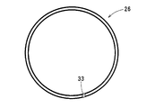
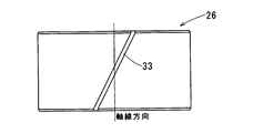
- 2nd bearing 26 is cylindrical as shown to FIG. 2A, FIG. 2B, and FIG. 2C, and the joint 33 which absorbs the difference of a linear expansion is formed so that an angle with respect to an axial direction may be formed.
- the reason why the abutment 33 is provided so as to form an angle with respect to the axial direction is to avoid a region where the shaft 7 does not contact in the axial direction and a region where the resistance during sliding increases. is there.
- the second bearing 26 is made of resin, general injection molding is possible, and the design freedom for the shape is high.
- the bearing portion 8 includes a first bearing 25 that supports one end side of the shaft 7 and a second bearing 26 that supports the other end side of the shaft 7.
- a seal member 27 that prevents fluid from entering the actuator 20 is disposed on one end side of the shaft 7.
- the housing 2 accommodates the second bearing 26 and is isolated from the outside.
- a chamber 30 is provided.
- the second bearing 26 is formed of a PPS resin material to which a fluororesin material is added.
- the second bearing 26 becomes a newly-provided bearing when the both-end supporting structure is adopted, and is formed of a PPS resin material to which a fluororesin material is added. Therefore, the second bearing 26 is exposed to a strong acid atmosphere. Will not corrode. Therefore, even when the shaft 7 of the EGR device 1 has a double-sided structure, corrosion of the second bearing 26 that is a newly provided bearing can be prevented.
- the second bearing is a bulk member, the effect does not disappear due to scraping or peeling, unlike the coating agent.
- the second bearing 26 is press-fitted into a storage chamber 30 provided in the housing 2, and the storage chamber 30 is isolated from the outside by closing the storage chamber 30 with a plug 32. There is no outflow of condensed water.
- an oil seal 28 including a fluororesin 27 b that is a seal member 27 that prevents intrusion of condensed water from the EGR flow path 5 to the actuator 20 side is disposed. ing.
- the fluororesin 27b as the seal member 27 that prevents the intrusion of the condensed water from the EGR flow path 5 to the actuator 20 side, the condensed water is more reliably used than by using a rubber member that swells with the condensed water and deteriorates the sealing performance. Can be prevented from entering.
- the first bearing 25 is a ball bearing that is fitted and held in the housing 2 and includes a fluoro rubber 27a that is a seal member 27 that prevents gas from entering from the EGR flow path 5 to the actuator 20 side.
- a fluoro rubber 27a that is a seal member 27 that prevents gas from entering from the EGR flow path 5 to the actuator 20 side.
- the second bearing 26 is a sliding bearing, but the second bearing 26 may be a rolling bearing such as a ball bearing or a needle bearing.
Landscapes
- Engineering & Computer Science (AREA)
- General Engineering & Computer Science (AREA)
- Mechanical Engineering (AREA)
- Chemical & Material Sciences (AREA)
- Combustion & Propulsion (AREA)
- Exhaust-Gas Circulating Devices (AREA)
- Lift Valve (AREA)
- Electrically Driven Valve-Operating Means (AREA)
- Details Of Valves (AREA)
Abstract
Description
実施例のEGR装置1の構成を、図1を用いて説明する。
本実施例におけるEGR装置1において、軸受け部8は、シャフト7の一端側を支持する第1軸受け25とシャフト7の他端側とを支持する第2軸受け26とを有している。また、シャフト7の一端側には、アクチュエータ20側への流体の浸入を防ぐシール部材27が配されており、ハウジング2には、第2軸受け26を収容するとともに、外部から隔絶されている収容室30が設けられている。そして、第2軸受け26は、フッ素樹脂材を添加したPPS樹脂材にて形成されている。
本開示は、その要旨を逸脱しない範囲で様々な変形例を考えることができる。
Claims (1)
- 内部にEGRガスの流れるEGR流路(5)の形成されるハウジング(2)と、
前記ハウジング(2)に軸受け部(8)を介して回動自在に支持されるシャフト(7)と、
前記シャフト(7)に固定され、前記シャフト(7)の回動に伴い回動することで、前記EGR流路(5)の開度を調整する弁体(11)と、
前記シャフト(7)の一端側に結合し、前記シャフト(7)を回動駆動するアクチュエータ(20)とを備えるEGR装置(1)であって、
前記軸受け部(8)は、前記シャフト(7)の一端側を支持する第1軸受け(25)と前記シャフト(7)の他端側とを支持する第2軸受け(26)とを有し、
前記シャフト(7)の一端側には、前記アクチュエータ(20)側への流体の浸入を防ぐシール部材(27)が配され、
前記ハウジング(2)には、前記第2軸受け(26)を収容するとともに、外部から隔絶されている収容室(30)が設けられ、
前記第2軸受け(26)は、フッ素樹脂材を添加したPPS樹脂材にて形成されるEGR装置(1)。
Priority Applications (3)
| Application Number | Priority Date | Filing Date | Title |
|---|---|---|---|
| CN201680004225.1A CN107110076A (zh) | 2015-03-31 | 2016-03-11 | Egr装置 |
| DE112016001522.4T DE112016001522B4 (de) | 2015-03-31 | 2016-03-11 | EGR-Vorrichtung |
| US15/542,749 US20180003134A1 (en) | 2015-03-31 | 2016-03-11 | Egr device |
Applications Claiming Priority (2)
| Application Number | Priority Date | Filing Date | Title |
|---|---|---|---|
| JP2015-074282 | 2015-03-31 | ||
| JP2015074282A JP6435969B2 (ja) | 2015-03-31 | 2015-03-31 | Egr装置 |
Publications (1)
| Publication Number | Publication Date |
|---|---|
| WO2016157756A1 true WO2016157756A1 (ja) | 2016-10-06 |
Family
ID=57004136
Family Applications (1)
| Application Number | Title | Priority Date | Filing Date |
|---|---|---|---|
| PCT/JP2016/001378 Ceased WO2016157756A1 (ja) | 2015-03-31 | 2016-03-11 | Egr装置 |
Country Status (5)
| Country | Link |
|---|---|
| US (1) | US20180003134A1 (ja) |
| JP (1) | JP6435969B2 (ja) |
| CN (1) | CN107110076A (ja) |
| DE (1) | DE112016001522B4 (ja) |
| WO (1) | WO2016157756A1 (ja) |
Families Citing this family (6)
| Publication number | Priority date | Publication date | Assignee | Title |
|---|---|---|---|---|
| JP6768427B2 (ja) * | 2016-06-01 | 2020-10-14 | 愛三工業株式会社 | 二重偏心弁 |
| JP6904897B2 (ja) * | 2017-12-25 | 2021-07-21 | 愛三工業株式会社 | Egrクーラシステム |
| DE102019101051A1 (de) * | 2019-01-16 | 2020-07-16 | Pierburg Gmbh | Abgasrückführventil für eine Verbrennungskraftmaschine |
| JP7146149B2 (ja) * | 2020-09-23 | 2022-10-03 | 三菱電機株式会社 | バルブ装置 |
| DE102022120289A1 (de) * | 2022-08-11 | 2024-02-22 | Purem GmbH | Stellklappenbaugruppe für einen Gasstrom in einem Brennstoffzellensystem |
| KR20240044909A (ko) * | 2022-09-29 | 2024-04-05 | 현대자동차주식회사 | 밸브 엑츄에이터 |
Citations (6)
| Publication number | Priority date | Publication date | Assignee | Title |
|---|---|---|---|---|
| JP2008133954A (ja) * | 2006-10-30 | 2008-06-12 | Ntn Corp | 弁装置用摺動部材及びこれを用いたすべり軸受 |
| JP2009103146A (ja) * | 2007-10-19 | 2009-05-14 | Taiho Kogyo Co Ltd | バルブアセンブリ |
| US20130167815A1 (en) * | 2011-11-23 | 2013-07-04 | Bernd Bareis | Low pressure valve, for controlling exhaust gas recirculation |
| WO2014131478A1 (de) * | 2013-02-28 | 2014-09-04 | Pierburg Gmbh | Klappenvorrichtung für eine verbrennungskraftmaschine |
| JP2015017506A (ja) * | 2013-07-09 | 2015-01-29 | 三菱電機株式会社 | 排気ガス再循環バルブ |
| JP2015059463A (ja) * | 2013-09-18 | 2015-03-30 | 株式会社デンソー | 流体制御弁 |
Family Cites Families (26)
| Publication number | Priority date | Publication date | Assignee | Title |
|---|---|---|---|---|
| JPS60201115A (ja) * | 1984-03-27 | 1985-10-11 | Daido Metal Kogyo Kk | 巻きブシユ軸受 |
| JPH037526U (ja) * | 1989-06-12 | 1991-01-24 | ||
| DE19730998C2 (de) * | 1996-07-19 | 2001-10-31 | Hitachi Ltd | Motorbetätigtes Durchflußmengensteuerventil und Abgasrückführungssteuerventil für Verbrennungsmotoren |
| US6390683B1 (en) * | 1999-06-11 | 2002-05-21 | Ntn Corporation | Heat insulation sleeve and bearing device for fixing roller |
| JP4303484B2 (ja) * | 2003-01-21 | 2009-07-29 | 大日本スクリーン製造株式会社 | メッキ装置 |
| JP4192763B2 (ja) * | 2003-11-07 | 2008-12-10 | 株式会社日立製作所 | 電子式egrガス制御装置 |
| JPWO2005052347A1 (ja) * | 2003-11-28 | 2007-06-21 | 株式会社日立製作所 | ディーゼルエンジンのegr制御装置およびモータ駆動式スロットル弁装置 |
| JP4695929B2 (ja) * | 2005-06-30 | 2011-06-08 | 日立オートモティブシステムズ株式会社 | 非接触式の回転角度検出装置とその製造方法及びそれを用いたスロットル弁制御装置 |
| JP4726752B2 (ja) * | 2005-10-25 | 2011-07-20 | 義治 山本 | 基板洗浄装置 |
| ES2349022T3 (es) * | 2007-11-08 | 2010-12-21 | Saint-Gobain Performance Plastics Pampus Gmbh | Cojinete. |
| JP5304995B2 (ja) * | 2008-09-09 | 2013-10-02 | Nok株式会社 | 密封装置の装着方法 |
| JP4706775B2 (ja) * | 2009-04-06 | 2011-06-22 | 株式会社デンソー | 内燃機関の吸気装置 |
| JP5348561B2 (ja) * | 2009-05-15 | 2013-11-20 | 株式会社リコー | 定着装置及び画像形成装置 |
| JP2011047454A (ja) * | 2009-08-26 | 2011-03-10 | Mitsubishi Heavy Ind Ltd | 遊星軸受構造 |
| JP2011058536A (ja) * | 2009-09-08 | 2011-03-24 | Denso Corp | 流体制御弁およびその製造方法 |
| JP6113444B2 (ja) * | 2011-09-22 | 2017-04-12 | Ntn株式会社 | フォイル軸受 |
| CN104067036B (zh) * | 2012-01-23 | 2016-09-28 | 大金工业株式会社 | 汽车用油封 |
| JP6013230B2 (ja) * | 2013-02-27 | 2016-10-25 | 株式会社小松製作所 | オイルシール |
| EP2772623B1 (en) * | 2013-02-28 | 2017-08-23 | MAHLE Filter Systems Japan Corporation | Air intake system for internal combustion engine |
| DE102013005677B3 (de) * | 2013-04-03 | 2014-07-17 | Geräte- und Pumpenbau GmbH Dr. Eugen Schmidt | Wellenlagerung mit Wellendichtung, insbesondere für Wasserpumpen in Kraftfahrzeugen |
| CN203614863U (zh) * | 2013-12-10 | 2014-05-28 | 温州市品一车辆配件有限公司 | Egr阀总成 |
| JP5726345B1 (ja) * | 2014-03-24 | 2015-05-27 | 三菱電線工業株式会社 | 軸シール |
| JP5657824B1 (ja) * | 2014-05-20 | 2015-01-21 | 三菱電線工業株式会社 | 軸シール |
| EP3173647B1 (en) * | 2014-07-23 | 2020-10-14 | NTN Corporation | Constant velocity universal joint |
| JP6449664B2 (ja) * | 2015-02-05 | 2019-01-09 | Kyb株式会社 | シール装置 |
| JP6572624B2 (ja) * | 2015-05-20 | 2019-09-11 | オイレス工業株式会社 | 滑り軸受及びそれを具備した軸受機構 |
-
2015
- 2015-03-31 JP JP2015074282A patent/JP6435969B2/ja active Active
-
2016
- 2016-03-11 DE DE112016001522.4T patent/DE112016001522B4/de active Active
- 2016-03-11 US US15/542,749 patent/US20180003134A1/en not_active Abandoned
- 2016-03-11 CN CN201680004225.1A patent/CN107110076A/zh active Pending
- 2016-03-11 WO PCT/JP2016/001378 patent/WO2016157756A1/ja not_active Ceased
Patent Citations (6)
| Publication number | Priority date | Publication date | Assignee | Title |
|---|---|---|---|---|
| JP2008133954A (ja) * | 2006-10-30 | 2008-06-12 | Ntn Corp | 弁装置用摺動部材及びこれを用いたすべり軸受 |
| JP2009103146A (ja) * | 2007-10-19 | 2009-05-14 | Taiho Kogyo Co Ltd | バルブアセンブリ |
| US20130167815A1 (en) * | 2011-11-23 | 2013-07-04 | Bernd Bareis | Low pressure valve, for controlling exhaust gas recirculation |
| WO2014131478A1 (de) * | 2013-02-28 | 2014-09-04 | Pierburg Gmbh | Klappenvorrichtung für eine verbrennungskraftmaschine |
| JP2015017506A (ja) * | 2013-07-09 | 2015-01-29 | 三菱電機株式会社 | 排気ガス再循環バルブ |
| JP2015059463A (ja) * | 2013-09-18 | 2015-03-30 | 株式会社デンソー | 流体制御弁 |
Also Published As
| Publication number | Publication date |
|---|---|
| DE112016001522B4 (de) | 2025-09-04 |
| JP2016194269A (ja) | 2016-11-17 |
| US20180003134A1 (en) | 2018-01-04 |
| DE112016001522T5 (de) | 2018-01-04 |
| JP6435969B2 (ja) | 2018-12-12 |
| CN107110076A (zh) | 2017-08-29 |
Similar Documents
| Publication | Publication Date | Title |
|---|---|---|
| WO2016157756A1 (ja) | Egr装置 | |
| JP7147710B2 (ja) | シールリング、弁装置 | |
| JP5673602B2 (ja) | バルブ装置 | |
| US8967125B2 (en) | EGR valve | |
| JP5355792B2 (ja) | ステップタイプバルブ | |
| JP5304825B2 (ja) | Egrバルブ | |
| US10330025B2 (en) | Valve device | |
| US11085543B2 (en) | Butterfly valve including a valve body, shaft, groove portion and seal ring | |
| JP5924247B2 (ja) | バルブ装置 | |
| JP2012163017A (ja) | バタフライバルブ | |
| JP6091364B2 (ja) | 排気ガス再循環バルブ | |
| US9915208B2 (en) | Flap device for an internal combustion engine | |
| JP2018059583A (ja) | バルブ装置 | |
| US9739311B2 (en) | Bearing structure and turbocharger | |
| JP5626270B2 (ja) | Egrバルブ | |
| US9556825B2 (en) | Valve device | |
| JP5850076B2 (ja) | バルブ装置 | |
| JP2013057259A (ja) | バルブ装置 | |
| JP2012107572A (ja) | Egrバルブ | |
| JP2012172519A (ja) | フラップバルブ | |
| JP6398855B2 (ja) | バルブ装置の製造方法 | |
| JP2013241899A (ja) | バルブ装置 |
Legal Events
| Date | Code | Title | Description |
|---|---|---|---|
| 121 | Ep: the epo has been informed by wipo that ep was designated in this application |
Ref document number: 16771650 Country of ref document: EP Kind code of ref document: A1 |
|
| WWE | Wipo information: entry into national phase |
Ref document number: 15542749 Country of ref document: US |
|
| WWE | Wipo information: entry into national phase |
Ref document number: 112016001522 Country of ref document: DE |
|
| 122 | Ep: pct application non-entry in european phase |
Ref document number: 16771650 Country of ref document: EP Kind code of ref document: A1 |
|
| WWG | Wipo information: grant in national office |
Ref document number: 112016001522 Country of ref document: DE |