WO2016152252A1 - 艶消金属調加飾シートとその製造方法 - Google Patents
艶消金属調加飾シートとその製造方法 Download PDFInfo
- Publication number
- WO2016152252A1 WO2016152252A1 PCT/JP2016/052889 JP2016052889W WO2016152252A1 WO 2016152252 A1 WO2016152252 A1 WO 2016152252A1 JP 2016052889 W JP2016052889 W JP 2016052889W WO 2016152252 A1 WO2016152252 A1 WO 2016152252A1
- Authority
- WO
- WIPO (PCT)
- Prior art keywords
- decorative sheet
- matte
- sheet
- thin film
- metal
- Prior art date
- Legal status (The legal status is an assumption and is not a legal conclusion. Google has not performed a legal analysis and makes no representation as to the accuracy of the status listed.)
- Ceased
Links
Images



Classifications
-
- B—PERFORMING OPERATIONS; TRANSPORTING
- B29—WORKING OF PLASTICS; WORKING OF SUBSTANCES IN A PLASTIC STATE IN GENERAL
- B29C—SHAPING OR JOINING OF PLASTICS; SHAPING OF MATERIAL IN A PLASTIC STATE, NOT OTHERWISE PROVIDED FOR; AFTER-TREATMENT OF THE SHAPED PRODUCTS, e.g. REPAIRING
- B29C45/00—Injection moulding, i.e. forcing the required volume of moulding material through a nozzle into a closed mould; Apparatus therefor
- B29C45/14—Injection moulding, i.e. forcing the required volume of moulding material through a nozzle into a closed mould; Apparatus therefor incorporating preformed parts or layers, e.g. injection moulding around inserts or for coating articles
-
- B—PERFORMING OPERATIONS; TRANSPORTING
- B32—LAYERED PRODUCTS
- B32B—LAYERED PRODUCTS, i.e. PRODUCTS BUILT-UP OF STRATA OF FLAT OR NON-FLAT, e.g. CELLULAR OR HONEYCOMB, FORM
- B32B15/00—Layered products comprising a layer of metal
-
- B—PERFORMING OPERATIONS; TRANSPORTING
- B32—LAYERED PRODUCTS
- B32B—LAYERED PRODUCTS, i.e. PRODUCTS BUILT-UP OF STRATA OF FLAT OR NON-FLAT, e.g. CELLULAR OR HONEYCOMB, FORM
- B32B3/00—Layered products comprising a layer with external or internal discontinuities or unevennesses, or a layer of non-planar shape; Layered products comprising a layer having particular features of form
- B32B3/26—Layered products comprising a layer with external or internal discontinuities or unevennesses, or a layer of non-planar shape; Layered products comprising a layer having particular features of form characterised by a particular shape of the outline of the cross-section of a continuous layer; characterised by a layer with cavities or internal voids ; characterised by an apertured layer
- B32B3/30—Layered products comprising a layer with external or internal discontinuities or unevennesses, or a layer of non-planar shape; Layered products comprising a layer having particular features of form characterised by a particular shape of the outline of the cross-section of a continuous layer; characterised by a layer with cavities or internal voids ; characterised by an apertured layer characterised by a layer formed with recesses or projections, e.g. hollows, grooves, protuberances, ribs
-
- B—PERFORMING OPERATIONS; TRANSPORTING
- B44—DECORATIVE ARTS
- B44C—PRODUCING DECORATIVE EFFECTS; MOSAICS; TARSIA WORK; PAPERHANGING
- B44C3/00—Processes, not specifically provided for elsewhere, for producing ornamental structures
- B44C3/02—Superimposing layers
Definitions
- the present invention relates to a matte metal tone decorative sheet capable of decorating a matte metal tone decoration to a molded product having a complicated three-dimensional shape with a high deep drawing degree, and a manufacturing method thereof.
- metallic decorations may be partially applied to give a high-class feeling, but depending on the parts, to prevent the driver's eyes from being dazzled by the reflection of light due to metallic luster. In some cases, it is necessary to suppress the metallic luster. In order to obtain such a molded product, it is known to use a matte metallic tone decorative sheet.
- Patent Document 1 discloses a method for forming a concavo-convex portion on a part of a base sheet, thereby delustering a metal thin film layer thereunder. It is disclosed. Further, Patent Document 2 discloses a method in which a mat layer is partially printed on a base material sheet to form irregularities so that the design layer and metal thin film layer below the mat layer are delustered.
- the present invention has been made to solve the above-described problems, and an object of the present invention is to provide a matte metal tone decorative sheet that can be easily decorated with a matte metal tone, and a method for producing the same. To do.
- the manufacturing method of the matte metallic tone decoration sheet of this invention heats the decoration sheet
- the base sheet is easily stretched by heating, but the metal thin film layer laminated on the base sheet cannot follow the stretch of the base sheet, Receives tensile force by the sheet. Therefore, microcracks can be generated uniformly in the metal thin film layer, and a matte metal tone decorative sheet can be obtained. That is, since it is not necessary to form unevenness or a mat layer partially on the base sheet, the number of production steps can be reduced, and the alignment accuracy of the boundary between the glossy part and the matte part can be improved. .
- the decorative sheet is obtained by laminating an adhesive layer on a metal thin film layer.
- the decorative sheet has a pattern layer laminated on a base sheet.
- the decorative sheet is obtained by laminating an anchor layer between a base sheet and a metal thin film layer.
- the adhesion between the metal thin film layer and the anchor layer can be improved.
- the anchor layer follows the stretching of the base sheet and a tensile force is applied to the metal thin film layer that is hardly stretched and is in close contact with the anchor layer, micro cracks can be generated uniformly in the metal thin film layer.
- the decorative sheet is obtained by laminating a release layer on a base sheet.
- the decorative sheet is obtained by laminating a release layer serving as the outermost surface of the transferred material on a base sheet.
- the heating of the decorative sheet includes a step of arranging the decorative sheet on the transfer object and a step of applying pressure and heat to the decorative sheet.
- the heating of the decorative sheet includes a step of feeding the decorative sheet into the mold and a step of closing the mold and applying pressure and heat to the decorative sheet by the molten resin to be injected. .
- the heating of the decorative sheet is performed by the step of feeding the decorative sheet into the mold, the step of preheating the decorative sheet, the mold is closed, and the molten resin is injected into the decorative sheet. Applying pressure and heat.
- the heating of the decorative sheet includes a step of preheating the decorative sheet, a step of preforming the decorative sheet, a step of feeding the preformed decorative sheet into the mold, and a mold. And a step of applying pressure and heat to the decorative sheet by the molten resin to be closed.
- the matte metallic tone decorative sheet of the present invention includes at least a stretchable base sheet and a metal thin film layer partially laminated on the base sheet, and the metal thin film layer is evenly heated. It is characterized by having a matte metallic tone by having generated microcracks.
- the base sheet is easily stretched by heating, but the metal thin film layer laminated on the base sheet cannot follow the stretch of the base sheet and receives a tensile force by the base sheet. Therefore, it becomes easy to generate microcracks uniformly in the metal thin film layer. That is, since it is not necessary to form unevenness or a mat layer partially on the base sheet, the number of production steps is reduced and the alignment accuracy of the boundary between the glossy part and the matte part can be improved.
- the metal thin film layer is made of a metal having lower stretchability than the base sheet.
- the metal thin film layer laminated on the base sheet cannot follow the stretching of the base sheet and receives a tensile force by the base sheet. Therefore, it is possible to easily generate microcracks uniformly in the metal thin film layer.
- the metal thin film layer is made of aluminum or chromium.
- an anchor layer is formed between the base sheet and the metal thin film layer.
- the adhesion between the metal thin film layer and the anchor layer can be improved.
- the anchor layer follows the stretching of the base sheet and a tensile force is applied to the metal thin film layer that is hardly stretched and is in close contact with the anchor layer, it is possible to easily generate microcracks uniformly in the metal thin film layer.
- the anchor layer is made of a material having higher stretchability than the metal thin film layer.
- the adhesion between the metal thin film layer and the anchor layer can be improved, and further, since the anchor layer is more easily stretched than the metal thin film layer, microcracks are easily generated uniformly in the metal thin film layer. be able to.
- the manufacturing method of the matte metallic tone decoration sheet of this invention heats the decoration sheet
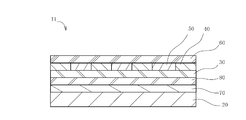
- FIG. 1 shows a matte metal-like decorative sheet 11 in which a metal thin film layer is laminated on a substrate sheet 20 and microcracks are uniformly generated by heating.
- the release layer 70, the release layer 80, and the anchor layer 30 are laminated on the base sheet, and the design layer 50 and the adhesive layer 60 are further formed, and the microcracks are uniformly generated by heating.
- the matte metal tone decorative sheet 11 is shown.
- 3 to 6 show examples of the embodiment of the heating step in the method for producing a matte metallic tone decorative sheet of the present invention.
- the base sheet 20 As the base sheet 20, a resin sheet that is easily stretched by heating and excellent in moldability can be used. Examples of such materials include acrylic resins, olefin resins, polyester resins, vinyl chloride resins, polycarbonate resins, ABS resins, and laminates thereof.
- the thickness of the base sheet 20 can be 20 ⁇ m to 600 ⁇ m.
- Metal thin film layer The metal thin film layer is partially formed on the base sheet in order to express a metallic decoration.
- a vacuum deposition method, a sputtering method, an ion plating method, a plating method, or the like may be used as a method for forming the metal thin film layer.
- the metal is not particularly limited, but in the present invention, a metal having a matte metal-like decorative sheet 11 by generating microcracks uniformly in the metal thin film layer is preferable, and a metal having lower stretchability than the base sheet is preferable.
- Aluminum or chromium is particularly preferable. By doing in this way, it can make it easy to generate a microcrack uniformly in a metal thin film layer.
- An anchor layer 30, a release layer 70, and a release layer 80 may be formed between the base sheet 20 and the metal thin film layer 40 in which microcracks are uniformly generated (see FIG. 2).
- the anchor layer 30 is preferably made of a resin that is easily stretched by heating. By doing in this way, the adhesiveness of a metal thin film layer can be improved.
- the material of the anchor layer 30 include acrylic resins, acrylic urethane resins, polyurethane resins, vinyl resins, epoxy resins, and polyester resins.
- a normal printing method such as a gravure printing method or a screen printing method, or a coating method such as a gravure coating method or a roll coating method may be used.
- the release layer 70 is formed in order to improve the peelability of the base sheet 20, and peels off together with the base sheet 20 when the base sheet 20 is peeled off.
- the release layer may be formed entirely on the base sheet.
- the release layer material include melamine resin release agents, silicon resin release agents, fluororesin release agents, cellulose resin release agents, paraffin release agents, and composite release agents thereof. Can be used.
- a coating method such as a roll coating method or a spray coating method, a printing method such as a gravure printing method, or a screen printing method may be used.
- the release layer 80 is formed so as to peel from the base sheet 20 or the release layer 70 and become the outermost surface of the transfer object when the base sheet 20 is peeled after transfer.
- the release layer is entirely formed on the base sheet or the release layer.
- the release layer can be made of acrylic resin, polyester resin, polyvinyl chloride resin, cellulose resin, rubber resin, polyurethane resin, polyvinyl acetate resin, or vinyl chloride-vinyl acetate copolymer system. It is preferable to use a resin or a copolymer such as ethylene-vinyl acetate copolymer resin.
- a photo-curing resin such as an ultraviolet curable resin, a radiation curable resin such as an electron beam curable resin, or a thermosetting resin may be selected and used.
- a normal printing method such as a gravure printing method or a screen printing method, or a coating method such as a gravure coating method or a roll coating method may be used.
- the design layer 50 may be formed between the partially formed metal thin film layers, and the adhesive layer 60 may be formed on the metal thin film layer and the design layer 50.
- Examples of the material of the pattern layer 50 include resins such as polyvinyl resins, polyamide resins, polyester resins, acrylic resins, polyurethane resins, polyvinyl acetal resins, polyester urethane resins, cellulose ester resins, alkyd resins.
- a colored ink containing a suitable color pigment or dye as a colorant may be used as a binder.
- a normal printing method such as a gravure printing method, a screen printing method, or an offset printing method, a roll coater method, or a transfer method may be used.
- the adhesive layer 60 is formed to adhere each of the above layers on the transfer object.
- a heat-sensitive or pressure-sensitive resin suitable for the material of the transfer object may be appropriately selected and used.
- the material of the transfer object is an acrylic resin
- an acrylic resin may be used.
- the material of the material to be transferred is polyphenylene oxide / polystyrene resin, polycarbonate resin, styrene copolymer resin, or polystyrene blend resin, acrylic resin, polystyrene resin, polyamide having affinity with these resins A series resin or the like may be used.
- the material of the transfer object is a polypropylene resin
- a chlorinated polyolefin resin a chlorinated ethylene-vinyl acetate copolymer resin, a cyclized rubber, a coumarone indene resin, or the like
- a method for forming the adhesive layer 60 a normal printing method such as a gravure printing method or a screen printing method, or a coating method such as a gravure coating method or a roll coating method may be used.
- the decorative sheet having the respective layers made of the above materials is heated to produce the matte metallic tone decorative sheet of the present invention.
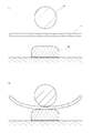
- a decorative sheet 10 in which a microcrack is not generated in a metal thin film layer is placed on an object to be transferred such as a molded product 100 (see FIG. 3A), and the decorative sheet 10 is heated by a heated roll 90. Heat and pressure are applied to (see FIG. 3B).
- the temperature of heat applied to the decorative sheet by the roll can be 170 to 240 ° C., and the pressure can be 0.1 to 1.0 MPa.
- the decorative sheet is stretched by heating with a roll, and microcracks can be evenly generated in the metal thin film layer. That is, the decoration sheet 10 can be made into the matte metal tone decoration sheet 11 by the heating by a roll. Further, the decorative sheet is further stretched by pressurization with a roll. By this action, microcracks can be generated more uniformly than when heating.
- the base material sheet 20 of the matte metal tone decorating sheet 11 can be peeled off, and the transfer layer of the matte metal tone decorating sheet 11 is formed into a molded product. By transferring to the surface, a molded product having a matte metallic decoration can be obtained. Furthermore, if the matte metal tone decorative sheet 11 has a release layer and a release layer, after peeling the base material sheet 20 of the matte metal tone decorating sheet 11, the molded product is exposed to, for example, ultraviolet rays. The release layer can be cured. That is, it is possible to obtain a molded article having a high surface hardness and a matte metallic decoration. When the metal thin film layer in which microcracks are generated uniformly is located on the outer surface of the molded product, a protective layer may be formed by painting after the molding process.
- the transfer layer of the matte metallic tone decorative sheet 11 is transferred to the molded product 100 by heating and pressurizing with a roll, and a molded product having a matte metallic tone decoration can be obtained.
- the decorative sheet 10 includes the base material sheet 20 and the anchor layer 30 selected from the above materials, the heat shrinkage rate when stretched by heating and heated at 160 ° C. for 3 minutes, for example, is 2.0% or more. It can be. As it is easy to stretch by heating, microcracks are generated even in the drying process after laminating the metal thin film layer, but it does not occur evenly in the metal thin film layer. Microcracks can be generated, and the matte metallic tone decorative sheet 11 of the present invention can be obtained.
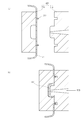
- the decorative sheet 10 is fed into the movable side 220 of the mold 200 (see FIG. 4A), fixed with the clamp member 230 and the like, and then the inside of the movable side cavity is vacuumed to bring the decorative sheet to the cavity surface.
- the mold is closed, the molten resin 110 is injected into the cavity from the fixed side 210, and heat and pressure are applied to the decorative sheet 10 (see FIG. 4B).
- the decorating sheet 10 is good to use the same thing as 1st embodiment.
- Method to send decorative sheet As a method of sending the decorative sheet 10 to the movable side 220, a single sheet of decorative sheet may be sent one by one, or a necessary part of a long decorative sheet may be sent intermittently. When a long decorative sheet is used, a feeding device having a positioning mechanism is used to send the decorative sheet, so that the register of the decorative sheet design layer and the cavity of the movable side 220 coincide with each other. Good.
- injection resin examples include general-purpose resins such as polystyrene resin, polyolefin resin, ABS resin, AS resin, and AN resin.
- general engineering resins such as polyphenylene oxide / polystyrene resins, polycarbonate resins, polyacetal resins, acrylic resins, polycarbonate-modified polyphenylene ether resins, polybutylene terephthalate resins, polybutylene terephthalate resins, ultrahigh molecular weight polyethylene resins, and polysulfone Super engineering resins such as resins, polyphenylene sulfide resins, polyphenylene oxide resins, polyarylate resins, polyetherimide resins, polyimide resins, liquid crystal polyester resins, and polyallyl heat-resistant resins can also be used.
- composite resins to which reinforcing materials such as glass fibers and inorganic fillers are added can also be used.
- the temperature of heat applied to the decorative sheet by the molten resin can be 200 to 320 ° C., and the pressure can be 19 to 50 MPa.
- the decorative sheet is stretched by heating with the injected molten resin, and microcracks can be generated uniformly in the metal thin film layer. That is, the decorative sheet 10 can be made into a matte metallic tone decorative sheet 11 by heating with a molten resin. Further, the decorative sheet is further stretched by pressurization with a molten resin. By this action, microcracks can be generated more uniformly than during heating.
- the matte metal tone decorative sheet 11 and the resin can be integrally formed by heating and pressurizing with the injected molten resin, and a molded article having a matte metal tone decoration can be obtained. it can. Moreover, the dimensional stability of a molded product can be ensured by integral molding.
- the base material sheet 20 of the matte metal tone decorating sheet 11 can be peeled off, and the transfer layer of the matte metal tone decorating sheet 11 is formed into a molded product. By transferring to the surface, a molded product having a matte metallic decoration can be obtained. Furthermore, if the matte metal tone decorative sheet 11 has a release layer and a release layer, after peeling the base material sheet 20 of the matte metal tone decorating sheet 11, the molded product is exposed to, for example, ultraviolet rays. The release layer can be cured. That is, it is possible to obtain a molded article having a high surface hardness and a matte metallic decoration. When the metal thin film layer 40 in which microcracks are uniformly generated is located on the outer surface of the molded product, a protective layer may be formed by painting after the molding process.
- thermoforming method As a preheating method, an infrared heater, an electric heater, a high frequency induction, a halogen lamp, a microwave, a high temperature derivative such as steam, a laser, or the like can be used.
- the temperature of heat applied to the decorative sheet by the heat source can be 100 to 250 ° C.
- the decorative sheet is stretched by preheating, and microcracks can be uniformly generated in the metal thin film layer. That is, the decorative sheet 10 can be made into a matte metallic tone decorative sheet 11 by preheating.
- the matte metal tone decorative sheet is stretched by heating with the molten resin, and the matte metal tone decorating sheet is further stretched by pressurization with the molten resin.
- the matte metal tone decorative sheet 11 and the resin can be integrally formed by heating and pressurizing with the injected molten resin, and a molded product having a matte metal tone decoration can be obtained.
- a protective layer may be formed by painting after the molding process.
- the decorative sheet 10 is fed into the preforming mold 400 and preheated by the heat source 300 (see FIG. 6A).
- the matte metal tone decorating sheet is preliminarily formed by vacuum suction or applying compressed air to the matte metal tone decorating sheet (see FIG. 6B). Unnecessary portions of the preformed matte metallic decoration sheet are trimmed, and the trimmed matte metallic decoration sheet is inserted into the cavity of the movable side 220 (see FIG. 6C).
- the inserted matte metallic decoration sheet may be fixed by a clamp member or vacuum suction.
- the mold is closed, the molten resin 110 is injected into the cavity from the fixed side 210, and heat and pressure are applied to the matte metal tone decorative sheet (see FIG. 6D).
- the matte metal tone decorative sheet is stretched by heating with the molten resin, and the matte metal tone decorating sheet is further stretched by pressurization with the molten resin.
- the matte metal tone decorative sheet 11 and the resin can be integrally formed by heating and pressurizing with the molten resin to be injected, and a molded product having a matte metal tone decoration can be obtained. Moreover, the dimensional stability of a molded product can be ensured by integral molding.
- a protective layer may be formed by painting after the molding process.
- a matte metallic decoration sheet can be obtained.
Landscapes
- Engineering & Computer Science (AREA)
- Manufacturing & Machinery (AREA)
- Mechanical Engineering (AREA)
- Laminated Bodies (AREA)
- Injection Moulding Of Plastics Or The Like (AREA)
Abstract
【課題】簡単に艶消金属調の装飾を施すことのできる艶消金属調加飾シートとその製造方法を提供することを目的とする。 【解決手段】延伸性を有する基材シート上に少なくとも金属薄膜層が部分的に積層された加飾シートを加熱して、金属薄膜層に均等にマイクロクラックを発生させて艶消金属調にすることを特徴とする。基材シートは加熱によって延伸させやすくなるが、金属薄膜層は基材シートの延伸に追随できず、基材シートによって引っ張り力を受ける。したがって、金属薄膜層に均等にマイクロクラックを発生させることができる。すなわち、基材シートに部分的に凹凸やマット層を形成する必要がないため、生産工程数を少なくすることができ、かつ艶部分と艶消し部分の境界の位置合わせ精度を良くすることができる。
Description
本発明は、深絞り度の高い複雑な立体形状を有する成形品に対して艶消金属調の装飾を施すことができる艶消金属調加飾シートとその製造方法に関する。
自動車の外装部品や内装部品などの樹脂成形品は、深絞り度の高い複雑な立体形状を有するものが多く、近年は多様な装飾を施した外装部品や内装部品が望まれている。
特に内装部品に関しては、高級感を出すために金属調の装飾を部分的に施す場合があるが、金属光沢による光の反射で運転者の目を眩ませないようにするために、部品によっては金属光沢を抑えなくてはならない場合がある。このような成形品を得るために、艶消金属調加飾シートを用いることが知られている。
加飾シートにおいて部分的に艶消金属調を実現する方法として、たとえば特許文献1には、基材シートの一部分に凹凸を形成することで、その下にある金属薄膜層の艶を消す方法が開示されている。また特許文献2には、基材シートに部分的にマット層を印刷して凹凸を形成することで、その下の図柄層や金属薄膜層の艶を消す方法が開示されている。
しかし上記2つの方法によれば、基材シート表面に部分的に凹凸を形成したり、基材シート表面に部分的にマット層を印刷したりする加工が必要になるために、次のような共通の課題が2つ生ずる。
(1)加飾シートの生産工程数が多く煩雑になる
(2)基材シート表面の凹凸またはマット層に対して、図柄層および金属薄膜層の位置を合わせる必要があるため、艶部分と艶消し部分との境界の位置合わせ精度が低下する
(1)加飾シートの生産工程数が多く煩雑になる
(2)基材シート表面の凹凸またはマット層に対して、図柄層および金属薄膜層の位置を合わせる必要があるため、艶部分と艶消し部分との境界の位置合わせ精度が低下する
本発明は、上記のような課題を解決するためになされたもので、簡単に艶消金属調の装飾を施すことのできる艶消金属調加飾シートとその製造方法を提供することを目的とする。
以下に、課題を解決するための手段として複数の態様を説明する。これらの態様は、必要に応じて任意に組み合わせることができる。
本発明の艶消金属調加飾シートの製造方法は、延伸性を有する基材シート上に少なくとも金属薄膜層が部分的に積層された加飾シートを加熱して、金属薄膜層に均等にマイクロクラックを発生させて艶消金属調にすることを特徴とするものである。
この態様の艶消金属調加飾シートの製造方法では、基材シートは加熱によって延伸させやすくなるが、基材シートに積層させた金属薄膜層は基材シートの延伸に追随できず、基材シートによって引っ張り力を受ける。したがって、金属薄膜層に均等にマイクロクラックを発生させることができ、艶消金属調加飾シートを得ることができる。すなわち、基材シートに部分的に凹凸やマット層を形成する必要がないため、生産工程数を少なくすることができ、かつ艶部分と艶消し部分の境界の位置合わせ精度を良くすることができる。
好ましい態様においては、加飾シートは、金属薄膜層上に接着層が積層されたものである。
好ましい態様においては、加飾シートは、基材シート上に絵柄層が積層されたものである。
好ましい態様においては、加飾シートは、基材シートと金属薄膜層との間にアンカー層が積層されたものである。この好ましい態様においては、金属薄膜層とアンカー層との密着性を向上することができる。またアンカー層が基材シートの延伸に追随し、アンカー層に密着した延伸しにくい金属薄膜層に引っ張り力が加わるため、金属薄膜層に均等にマイクロクラックを発生させることができる。
好ましい態様においては、加飾シートは、基材シート上に離型層が積層されたものである。
好ましい態様においては、加飾シートは、基材シート上に被転写物の最外面となる剥離層が積層されたものである。
これらの好ましい態様においては、加飾シートの加熱は、被転写物上に加飾シートを配置する工程と、加飾シートに圧力および熱を加える工程とを含むものである。
好ましい態様においては、加飾シートの加熱は、金型内に加飾シートを送り込む工程と、金型を閉じて、射出される溶融樹脂により加飾シートに圧力および熱を加える工程とを含むものである。
好ましい態様においては、加飾シートの加熱は、金型内に加飾シートを送り込む工程と、加飾シートを予備加熱する工程と、金型を閉じて、射出される溶融樹脂により加飾シートに圧力および熱を加える工程とを含むものである。
好ましい態様においては、加飾シートの加熱は、加飾シートを予備加熱する工程と、加飾シートを予備成形する工程と、金型内に予備成形した加飾シートを送り込む工程と、金型を閉じて、射出される溶融樹脂により加飾シートに圧力および熱を加える工程とを含むものである。
本発明の艶消金属調加飾シートは、延伸性を有する基材シートと、前記基材シート上に部分的に積層された金属薄膜層とを少なくとも含み、前記金属薄膜層が加熱により均等に発生させられたマイクロクラックを有することにより艶消金属調を示すことを特徴とするものである。
この好ましい態様においては、基材シートは加熱によって延伸しやすくなるが、基材シートに積層された金属薄膜層は基材シートの延伸に追随できず、基材シートによって引っ張り力を受ける。したがって、金属薄膜層に均等にマイクロクラックが発生させられやすくなる。すなわち、基材シートに部分的に凹凸やマット層を形成する必要がないため、生産工程数が少なく簡略になり、かつ艶部分と艶消し部分の境界の位置合わせ精度を良くすることができる。
好ましい態様においては、金属薄膜層が、基材シートよりも低い延伸性を有する金属からなるものである。
この好ましい態様においては、基材シートに積層させた金属薄膜層は基材シートの延伸に追随できず、基材シートによって引っ張り力を受ける。したがって、金属薄膜層に均等にマイクロクラックを発生させやすくすることができる。
好ましい態様においては、金属薄膜層がアルミニウムまたはクロムからなるものである。
好ましい態様においては、基材シートと金属薄膜層との間にアンカー層が形成されたものである。
この好ましい態様においては、金属薄膜層とアンカー層との密着性を向上させることができる。また、アンカー層が基材シートの延伸に追随し、アンカー層に密着した延伸しにくい金属薄膜層に引っ張り力が加わるため、金属薄膜層に均等にマイクロクラックを発生させやすくすることができる。
この好ましい態様においては、アンカー層が、金属薄膜層よりも高い延伸性を有する材質からなるものである。
この好ましい態様においては、金属薄膜層とアンカー層との密着性を向上させることができ、さらにアンカー層が金属薄膜層よりも延伸しやすいため、金属薄膜層に均等にマイクロクラックを発生させやすくすることができる。
本発明によれば、簡単に艶消金属調の装飾を施すことのできる艶消金属調加飾シートとその製造方法を提供することができる。
以下、図面を参照しながら、本発明の艶消金属調加飾シートとその製造方法について、実施形態の一例を説明する。
本発明の艶消金属調加飾シートの製造方法は、延伸性を有する基材シート上に少なくとも金属薄膜層が部分的に積層された加飾シートを加熱して、金属薄膜層に均等にマイクロクラックを発生させて艶消金属調にすることを特徴とするものである。
図1に、基材シート20上に金属薄膜層が積層され、加熱することによってマイクロクラックが均等に発生させられた艶消金属調加飾シート11を示す。図2に、基材シート上に離型層70、剥離層80、アンカー層30が積層され、さらに図柄層50および接着層60が形成され、加熱することによってマイクロクラックが均等に発生させられた艶消金属調加飾シート11を示す。図3~図6に、本発明の艶消金属調加飾シートの製造方法における加熱工程の実施形態の例を示す。
<第一実施形態>
まず、第一実施形態について説明する。
まず、第一実施形態について説明する。
(基材シート)
基材シート20としては、加熱によって延伸しやすく成形性に優れた樹脂シートを用いることができる。そのような材質としては、アクリル系樹脂、オレフィン系樹脂ポリエステル系樹脂、塩ビ系樹脂、ポリカーボネート系樹脂、ABS系樹脂およびそれらの積層品が挙げられる。また基材シート20の厚みは、20μm~600μmとすることができる。
基材シート20としては、加熱によって延伸しやすく成形性に優れた樹脂シートを用いることができる。そのような材質としては、アクリル系樹脂、オレフィン系樹脂ポリエステル系樹脂、塩ビ系樹脂、ポリカーボネート系樹脂、ABS系樹脂およびそれらの積層品が挙げられる。また基材シート20の厚みは、20μm~600μmとすることができる。
(金属薄膜層)
金属薄膜層は、金属調の装飾を表現するために、基材シート上に部分的に形成する。金属薄膜層の形成方法としては、真空蒸着法、スパッタリング法、イオンプレーティング法、めっき法などを用いるとよい。金属としては、特に限定されないが、本発明では金属薄膜層にマイクロクラックを均等に発生させることで艶消金属調加飾シート11を得るため、基材シートよりも延伸性が低い金属が好ましく、特にアルミニウムまたはクロムが好ましい。このようにすることで、金属薄膜層に均等にマイクロクラックを発生させやすくすることができる。
金属薄膜層は、金属調の装飾を表現するために、基材シート上に部分的に形成する。金属薄膜層の形成方法としては、真空蒸着法、スパッタリング法、イオンプレーティング法、めっき法などを用いるとよい。金属としては、特に限定されないが、本発明では金属薄膜層にマイクロクラックを均等に発生させることで艶消金属調加飾シート11を得るため、基材シートよりも延伸性が低い金属が好ましく、特にアルミニウムまたはクロムが好ましい。このようにすることで、金属薄膜層に均等にマイクロクラックを発生させやすくすることができる。
(その他の層)
基材シート20とマイクロクラックが均等に発生した金属薄膜層40との間には、アンカー層30、離型層70、剥離層80を形成してもよい(図2参照)。アンカー層30は、加熱によって延伸しやすい樹脂を用いることが好ましい。このようにすることで金属薄膜層の密着性を向上することができる。アンカー層30の材質としては、アクリル系樹脂、アクリルウレタン系樹脂、ポリウレタン系樹脂、ビニル系樹脂、エポキシ系樹脂、ポリエステル系樹脂が挙げられる。アンカー層30の形成方法としては、グラビア印刷法、スクリーン印刷法などの通常の印刷法や、グラビアコート法、ロールコート法などのコート法を用いるとよい。
基材シート20とマイクロクラックが均等に発生した金属薄膜層40との間には、アンカー層30、離型層70、剥離層80を形成してもよい(図2参照)。アンカー層30は、加熱によって延伸しやすい樹脂を用いることが好ましい。このようにすることで金属薄膜層の密着性を向上することができる。アンカー層30の材質としては、アクリル系樹脂、アクリルウレタン系樹脂、ポリウレタン系樹脂、ビニル系樹脂、エポキシ系樹脂、ポリエステル系樹脂が挙げられる。アンカー層30の形成方法としては、グラビア印刷法、スクリーン印刷法などの通常の印刷法や、グラビアコート法、ロールコート法などのコート法を用いるとよい。
離型層70は、基材シート20の剥離性を高めるために形成し、基材シート20を剥離した際に、基材シート20とともに剥離する。離型層は基材シート上に全面的に形成してもよい。離型層の材質としては、メラミン樹脂系離型剤、シリコン樹脂系離型剤、フッ素樹脂系離型剤、セルロース樹脂系離型剤、パラフィン系離型剤およびこれらの複合型離型剤などを用いることができる。離型層の形成方法としては、ロールコート法、スプレーコート法などのコート法、グラビア印刷法、スクリーン印刷法などの印刷法を用いるとよい。
剥離層80は、転写後に基材シート20を剥離した際に、基材シート20または離型層70から剥離して被転写物の最外面となるように形成する。剥離層は基材シート上または離型層上に全面的に形成する。剥離層の材質としては、アクリル系樹脂、ポリエステル系樹脂、ポリ塩化ビニル系樹脂、セルロース系樹脂、ゴム系樹脂、ポリウレタン系樹脂、ポリ酢酸ビニル系樹脂などの他、塩化ビニル―酢酸ビニル共重合体系樹脂、エチレン―酢酸ビニル共重合体系樹脂などのコポリマーを用いるとよい。剥離層に硬度が必要な場合には、紫外線硬化性樹脂などの光硬化性樹脂、電子線硬化性樹脂などの放射線硬化性樹脂、熱硬化性樹脂などを選定して用いるとよい。剥離層の形成方法としては、グラビア印刷法、スクリーン印刷法などの通常の印刷法や、グラビアコート法、ロールコート法などのコート法を用いるとよい。
また、部分的に形成された金属薄膜層の間に図柄層50を形成してもよく、金属薄膜層および図柄層50上に接着層60を形成してもよい。
図柄層50の材質としては、ポリビニル系樹脂、ポリアミド系樹脂、ポリエステル系樹脂、アクリル系樹脂、ポリウレタン系樹脂、ポリビニルアセタール系樹脂、ポリエステルウレタン系樹脂、セルロースエステル系樹脂、アルキド系樹脂などの樹脂をバインダーとし、適切な色の顔料または染料を着色剤として含有する着色インキを用いるとよい。図柄層50の形成方法としては、グラビア印刷法、スクリーン印刷法、オフセット印刷法などの通常の印刷法やロールコーター法あるいは転写法などを用いるとよい。
接着層60は、被転写物上に上記の各層を接着するために形成する。接着層60としては、被転写物の材質に適した感熱性または感圧性の樹脂を適宜選択して用いるとよい。たとえば、被転写物の材質がアクリル系樹脂の場合は、アクリル系樹脂を用いるとよい。また、被転写物の材質がポリフェニレンオキシド・ポリスチレン系樹脂、ポリカーボネート系樹脂、スチレン共重合体系樹脂、ポリスチレン系ブレンド樹脂の場合は、これらの樹脂と親和性のあるアクリル系樹脂、ポリスチレン系樹脂、ポリアミド系樹脂などを使用すればよい。さらに、被転写物の材質がポリプロピレン樹脂の場合は、塩素化ポリオレフィン樹脂、塩素化エチレン‐酢酸ビニル共重合体樹脂、環化ゴム、クマロンインデン樹脂などを使用すればよい。接着層60の形成方法としては、グラビア印刷法、スクリーン印刷法などの通常の印刷法や、グラビアコート法、ロールコート法などのコート法を用いるとよい。
上記の材料からなる各層を有する加飾シートを加熱して、本発明の艶消金属調加飾シートを製造する。まず、成形品100などの被転写物上に、金属薄膜層にマイクロクラックが発生していない加飾シート10を配置し(図3(a)参照)、加熱されたロール90によって加飾シート10に熱と圧力を加える(図3(b)参照)。
ロールによって加飾シートに加えられる熱の温度は170~240℃とすることができ、圧力は0.1~1.0MPaとすることができる。
ロールによる加熱によって加飾シートが延伸され、金属薄膜層に均等にマイクロクラックを発生させることができる。すなわちロールによる加熱によって、加飾シート10は艶消金属調加飾シート11にすることができる。また、ロールによる加圧によって加飾シートはさらに延伸される。この作用によって、加熱時よりも均等にマイクロクラックを発生させることができる。
艶消金属調加飾シート11が離型層を有するものであれば、艶消金属調加飾シート11の基材シート20を剥離でき、艶消金属調加飾シート11の転写層を成形品表面に転写することで艶消金属調の装飾を有する成形品を得ることができる。さらに艶消金属調加飾シート11が離型層および剥離層を有するものであれば、艶消金属調加飾シート11の基材シート20を剥離した後、成形品をたとえば紫外線に当てることで剥離層を硬化することができる。すなわち表面硬度が高く、艶消金属調の装飾を有する成形品を得ることができる。マイクロクラックが均等に発生した金属薄膜層が成形品外面に位置する場合には、成形加工後に塗装によって保護層を形成してもよい。
ロールによる加熱および加圧によって艶消金属調加飾シート11の転写層が成形品100に転写され、艶消金属調の装飾を有する成形品を得ることができる。
なお、加飾シート10は上記の材質から選択された基材シート20およびアンカー層30を含むため、加熱によって延伸され、たとえば160℃で3分加熱した時の加熱収縮率を2.0%以上とすることができる。そのように加熱によって延伸しやすいため、金属薄膜層を積層した後の乾燥工程などでもマイクロクラックは発生するが、金属薄膜層に均等に発生することはなく、上記の加熱工程を経ることで均等にマイクロクラックを発生させることができ、本発明の艶消金属調加飾シート11を得ることができる。
<第二実施形態>
次に第二実施形態について説明する。
次に第二実施形態について説明する。
(概要)
金型200のうち可動側220へ加飾シート10を送り込み(図4(a)参照)、クランプ部材230などで固定した後、可動側のキャビティ内を真空吸引して加飾シートをキャビティ表面に密着させ、金型を閉じて固定側210から溶融樹脂110をキャビティへ射出して加飾シート10に熱と圧力を加える(図4(b)参照)。なお、加飾シート10は第一実施形態と同じものを使用するとよい。
金型200のうち可動側220へ加飾シート10を送り込み(図4(a)参照)、クランプ部材230などで固定した後、可動側のキャビティ内を真空吸引して加飾シートをキャビティ表面に密着させ、金型を閉じて固定側210から溶融樹脂110をキャビティへ射出して加飾シート10に熱と圧力を加える(図4(b)参照)。なお、加飾シート10は第一実施形態と同じものを使用するとよい。
(加飾シートを送り込む方法)
加飾シート10を可動側220へ送り込む方法としては、枚葉の加飾シートを1枚ずつ送り込んでもよいし、長尺の加飾シートの必要部分を間欠的に送り込んでもよい。長尺の加飾シートを使用する場合、加飾シートを送り込むには位置決め機構を有する送り装置を使用して、加飾シートの図柄層と可動側220のキャビティとの見当が一致するようにするとよい。
加飾シート10を可動側220へ送り込む方法としては、枚葉の加飾シートを1枚ずつ送り込んでもよいし、長尺の加飾シートの必要部分を間欠的に送り込んでもよい。長尺の加飾シートを使用する場合、加飾シートを送り込むには位置決め機構を有する送り装置を使用して、加飾シートの図柄層と可動側220のキャビティとの見当が一致するようにするとよい。
(射出樹脂)
射出樹脂としては、ポリスチレン系樹脂、ポリオレフィン系樹脂、ABS樹脂、AS樹脂、AN樹脂などの汎用樹脂を挙げることができる。また、ポリフェニレンオキシド・ポリスチレン系樹脂、ポリカーボネート系樹脂、ポリアセタール系樹脂、アクリル系樹脂、ポリカーボネート変性ポリフェニレンエーテル樹脂、ポリブチレンテレフタレート樹脂、ポリブチレンテレフタレート樹脂、超高分子量ポリエチレン樹脂などの汎用エンジニアリング樹脂や、ポリスルホン樹脂、ポリフェニレンサルファイド系樹脂、ポリフェニレンオキシド系樹脂、ポリアリレート樹脂、ポリエーテルイミド樹脂、ポリイミド樹脂、液晶ポリエステル樹脂、ポリアリル系耐熱樹脂などのスーパーエンジニアリング樹脂を使用することもできる。さらに、ガラス繊維や無機フィラーなどの補強材を添加した複合樹脂も使用できる。
射出樹脂としては、ポリスチレン系樹脂、ポリオレフィン系樹脂、ABS樹脂、AS樹脂、AN樹脂などの汎用樹脂を挙げることができる。また、ポリフェニレンオキシド・ポリスチレン系樹脂、ポリカーボネート系樹脂、ポリアセタール系樹脂、アクリル系樹脂、ポリカーボネート変性ポリフェニレンエーテル樹脂、ポリブチレンテレフタレート樹脂、ポリブチレンテレフタレート樹脂、超高分子量ポリエチレン樹脂などの汎用エンジニアリング樹脂や、ポリスルホン樹脂、ポリフェニレンサルファイド系樹脂、ポリフェニレンオキシド系樹脂、ポリアリレート樹脂、ポリエーテルイミド樹脂、ポリイミド樹脂、液晶ポリエステル樹脂、ポリアリル系耐熱樹脂などのスーパーエンジニアリング樹脂を使用することもできる。さらに、ガラス繊維や無機フィラーなどの補強材を添加した複合樹脂も使用できる。
溶融樹脂によって加飾シートに加えられる熱の温度は200~320℃とすることができ、圧力は19~50MPaとすることができる。
射出される溶融樹脂による加熱によって加飾シートが延伸され、金属薄膜層に均等にマイクロクラックを発生させることができる。すなわち溶融樹脂による加熱によって、加飾シート10は艶消金属調加飾シート11にすることができる。また溶融樹脂による加圧によって加飾シートはさらに延伸される。この作用によって加熱時よりも均等にマイクロクラックを発生させることができる。
この実施形態においては、射出される溶融樹脂による加熱および加圧によって艶消金属調加飾シート11と樹脂とを一体成形することができ、艶消金属調の装飾を有する成形品を得ることができる。また、一体成形することによって、成形品の寸法安定性を確保することができる。
艶消金属調加飾シート11が離型層を有するものであれば、艶消金属調加飾シート11の基材シート20を剥離でき、艶消金属調加飾シート11の転写層を成形品表面に転写することで艶消金属調の装飾を有する成形品を得ることができる。さらに艶消金属調加飾シート11が離型層および剥離層を有するものであれば、艶消金属調加飾シート11の基材シート20を剥離した後、成形品をたとえば紫外線に当てることで剥離層を硬化することができる。すなわち表面硬度が高く、艶消金属調の装飾を有する成形品を得ることができる。マイクロクラックが均等に発生した金属薄膜層40が成形品外面に位置する場合には、成形加工後に塗装によって保護層を形成してもよい。
<第三実施形態>
続いて第三実施形態について説明する。射出樹脂、加飾シート、金型、固定側、可動側、加飾シートを送り込む方法については第二実施形態と同じものを使用するとよい。
続いて第三実施形態について説明する。射出樹脂、加飾シート、金型、固定側、可動側、加飾シートを送り込む方法については第二実施形態と同じものを使用するとよい。
(概要)
金型200のうち可動側220へ加飾シート10を送り込み、クランプ部材230などで固定した後、熱源300を用いて加飾シートを予備加熱する(図5(a)参照)。次に、可動側のキャビティ内を真空吸引して加飾シートをキャビティ表面に密着させ、金型を閉じて固定側210から溶融樹脂110をキャビティへ射出して加飾シート10に熱と圧力を加える(図5(b)参照)。
金型200のうち可動側220へ加飾シート10を送り込み、クランプ部材230などで固定した後、熱源300を用いて加飾シートを予備加熱する(図5(a)参照)。次に、可動側のキャビティ内を真空吸引して加飾シートをキャビティ表面に密着させ、金型を閉じて固定側210から溶融樹脂110をキャビティへ射出して加飾シート10に熱と圧力を加える(図5(b)参照)。
(予備加熱の方法)
予備加熱の方法としては、赤外線ヒーター、電気ヒーター、高周波誘導、ハロゲンランプ、マイクロ波、スチームなどの高温誘導体、レーザーなどの方法を用いることができる。熱源によって加飾シートに加えられる熱の温度は100~250℃とすることができる。予備加熱によって加飾シートが延伸され、金属薄膜層に均等にマイクロクラックを発生させることができる。すなわち予備加熱によって、加飾シート10は艶消金属調加飾シート11にすることができる。
予備加熱の方法としては、赤外線ヒーター、電気ヒーター、高周波誘導、ハロゲンランプ、マイクロ波、スチームなどの高温誘導体、レーザーなどの方法を用いることができる。熱源によって加飾シートに加えられる熱の温度は100~250℃とすることができる。予備加熱によって加飾シートが延伸され、金属薄膜層に均等にマイクロクラックを発生させることができる。すなわち予備加熱によって、加飾シート10は艶消金属調加飾シート11にすることができる。
この実施形態において、溶融樹脂による加熱によって艶消金属調加飾シートが延伸され、溶融樹脂による加圧によって艶消金属調加飾シートはさらに延伸される。これらの作用によって、予備加熱時よりも均等にマイクロクラックを発生させることができる。
また、射出される溶融樹脂による加熱および加圧によって艶消金属調加飾シート11と樹脂とを一体成形することができ、艶消金属調の装飾を有する成形品を得ることができる。一体成形することによって、成形品の寸法安定性を確保することができる。マイクロクラックが均等に発生した金属薄膜層40が成形品外面に位置する場合には、成形加工後に塗装により保護層を形成してもよい。
<第四実施形態>
最後に第四実施形態について説明する。射出樹脂、加飾シート、予備加熱の方法、金型、固定側、可動側、加飾シートを送り込む方法については第三実施形態と同じものを使用するとよい。
最後に第四実施形態について説明する。射出樹脂、加飾シート、予備加熱の方法、金型、固定側、可動側、加飾シートを送り込む方法については第三実施形態と同じものを使用するとよい。
(概要)
予備成形用金型400に加飾シート10を送り込み、熱源300によって予備加熱する(図6(a)参照)。次に艶消金属調加飾シートを真空吸引し、または艶消金属調加飾シートに圧縮空気を与えることによって艶消金属調加飾シートを予備成形する(図6(b)参照)。予備成形した艶消金属調加飾シートの不要部分をトリミングし、トリミングした艶消金属調加飾シートを可動側220のキャビティに挿入する(図6(c)参照)。挿入した艶消金属調加飾シートは、クランプ部材や真空吸引などによって固定してもよい。続いて金型を閉じて固定側210から溶融樹脂110をキャビティへ射出して艶消金属調加飾シートに熱と圧力を加える(図6(d)参照)。
予備成形用金型400に加飾シート10を送り込み、熱源300によって予備加熱する(図6(a)参照)。次に艶消金属調加飾シートを真空吸引し、または艶消金属調加飾シートに圧縮空気を与えることによって艶消金属調加飾シートを予備成形する(図6(b)参照)。予備成形した艶消金属調加飾シートの不要部分をトリミングし、トリミングした艶消金属調加飾シートを可動側220のキャビティに挿入する(図6(c)参照)。挿入した艶消金属調加飾シートは、クランプ部材や真空吸引などによって固定してもよい。続いて金型を閉じて固定側210から溶融樹脂110をキャビティへ射出して艶消金属調加飾シートに熱と圧力を加える(図6(d)参照)。
この実施形態において、溶融樹脂による加熱によって艶消金属調加飾シートが延伸され、溶融樹脂による加圧によって艶消金属調加飾シートはさらに延伸される。これらの作用によって、予備加熱時よりも均等にマイクロクラックを発生させることができる。
射出される溶融樹脂による加熱および加圧によって艶消金属調加飾シート11と樹脂とを一体成形することができ、艶消金属調の装飾を有する成形品を得ることができる。また一体成形することによって、成形品の寸法安定性を確保することができる。マイクロクラックが均等に発生した金属薄膜層40が成形品外面に位置する場合には、成形加工後に塗装により保護層を形成してもよい。
以上のようにして、艶消金属調加飾シートを得ることができる。
10:加飾シート
20:基材シート
30:アンカー層
40:マイクロクラックが均等に発生した金属薄膜層
50:図柄層
60:接着層
70:離型層
80:剥離層
90:ロール
100:成形品
110:溶融樹脂
200:金型
210:固定側
220:可動側
230:クランプ部材
300:熱源
400:予備成形用金型
20:基材シート
30:アンカー層
40:マイクロクラックが均等に発生した金属薄膜層
50:図柄層
60:接着層
70:離型層
80:剥離層
90:ロール
100:成形品
110:溶融樹脂
200:金型
210:固定側
220:可動側
230:クランプ部材
300:熱源
400:予備成形用金型
Claims (15)
- 延伸性を有する基材シート上に少なくとも金属薄膜層が部分的に積層された加飾シートを加熱して、前記金属薄膜層に均等にマイクロクラックを発生させて艶消金属調にすることを特徴とする艶消金属調加飾シートの製造方法。
- 前記加飾シートは、前記金属薄膜層上に接着層が積層されたものである請求項1に記載の艶消金属調加飾シートの製造方法。
- 前記加飾シートは、前記基材シート上に絵柄層が積層されたものである請求項1または2に記載の艶消金属調加飾シートの製造方法。
- 前記加飾シートは、前記基材シートと前記金属薄膜層との間にアンカー層が積層されたものである請求項1~3のいずれか一項に記載の艶消金属調加飾シートの製造方法。
- 前記加飾シートは、前記基材シート上に離型層が積層されたものである請求項1~4のいずれか一項に記載の艶消金属調加飾シートの製造方法。
- 前記加飾シートは、前記基材シート上に被転写物の最外面となる剥離層が積層されたものである請求項1~5のいずれか一項に記載の艶消金属調加飾シートの製造方法。
- 前記加飾シートの加熱は、
被転写物上に前記加飾シートを配置する工程と、
前記加飾シートに圧力および熱を加える工程と
を含むものである請求項5または6に記載の艶消金属調加飾シートの製造方法。 - 前記加飾シートの加熱は、
金型内に前記加飾シートを送り込む工程と、
前記金型を閉じて、射出される溶融樹脂により前記加飾シートに圧力および熱を加える工程と
を含むものである請求項1~6のいずれか一項に記載の艶消金属調加飾シートの製造方法。 - 前記加飾シートの加熱は、
金型内に前記加飾シートを送り込む工程と、
前記加飾シートを予備加熱する工程と、
前記金型を閉じて、射出される溶融樹脂により前記加飾シートに圧力および熱を加える工程と
を含むものである請求項1~4のいずれか一項に記載の艶消金属調加飾シートの製造方法。 - 前記加飾シートの加熱は、
前記加飾シートを予備加熱する工程と、
前記加飾シートを予備成形する工程と、
金型内に予備成形した前記加飾シートを送り込む工程と、
前記金型を閉じて、射出される溶融樹脂により前記加飾シートに圧力および熱を加える工程と
を含むものである請求項1~4のいずれか一項に記載の艶消金属調加飾シートの製造方法。 - 延伸性を有する基材シートと、前記基材シート上に部分的に積層された金属薄膜層とを少なくとも含み、前記金属薄膜層が加熱により均等に発生させられたマイクロクラックを有することにより艶消金属調を示すことを特徴とする艶消金属調加飾シート。
- 前記金属薄膜層が、前記基材シートよりも低い延伸性を有する金属からなるものである請求項11に記載の艶消金属調加飾シート。
- 前記金属薄膜層がアルミニウムまたはクロムからなるものである請求項11または12に記載の艶消金属調加飾シート。
- 前記基材シートと前記金属薄膜層との間にアンカー層が形成されたものである請求項11~13のいずれか一項に記載の艶消金属調加飾シート。
- 前記アンカー層が、前記金属薄膜層よりも高い延伸性を有する材質からなるものである請求項14に記載の艶消金属調加飾シート。
Applications Claiming Priority (2)
| Application Number | Priority Date | Filing Date | Title |
|---|---|---|---|
| JP2015-058742 | 2015-03-20 | ||
| JP2015058742A JP2016175348A (ja) | 2015-03-20 | 2015-03-20 | 艶消金属調加飾シートとその製造方法 |
Publications (1)
| Publication Number | Publication Date |
|---|---|
| WO2016152252A1 true WO2016152252A1 (ja) | 2016-09-29 |
Family
ID=56979023
Family Applications (1)
| Application Number | Title | Priority Date | Filing Date |
|---|---|---|---|
| PCT/JP2016/052889 Ceased WO2016152252A1 (ja) | 2015-03-20 | 2016-02-01 | 艶消金属調加飾シートとその製造方法 |
Country Status (2)
| Country | Link |
|---|---|
| JP (1) | JP2016175348A (ja) |
| WO (1) | WO2016152252A1 (ja) |
Cited By (1)
| Publication number | Priority date | Publication date | Assignee | Title |
|---|---|---|---|---|
| WO2017179463A1 (ja) * | 2016-04-12 | 2017-10-19 | ソニー株式会社 | 構造体、電子機器、加飾フィルム、及び構造体の製造方法 |
Families Citing this family (2)
| Publication number | Priority date | Publication date | Assignee | Title |
|---|---|---|---|---|
| JP6084758B2 (ja) * | 2014-12-01 | 2017-02-22 | 株式会社タイカ | 水圧転写方法及び水圧転写シート |
| JP2023057485A (ja) * | 2021-10-11 | 2023-04-21 | 大日本印刷株式会社 | 加飾フィルム、加飾部材、移動体および加飾部材の製造方法 |
Citations (12)
| Publication number | Priority date | Publication date | Assignee | Title |
|---|---|---|---|---|
| JPH05318567A (ja) * | 1992-05-19 | 1993-12-03 | Toyo Alum Kk | 容器状成形体 |
| JPH11131213A (ja) * | 1997-10-29 | 1999-05-18 | Hashimoto Forming Ind Co Ltd | 表面光輝製品の製造方法 |
| JP2001260596A (ja) * | 2000-03-21 | 2001-09-25 | Nissha Printing Co Ltd | 部分マットハードコート転写材と部分マットハードコート成形品の製造方法 |
| JP2002256455A (ja) * | 2001-03-06 | 2002-09-11 | Toyoda Gosei Co Ltd | めっき製品の製造方法 |
| JP2002292783A (ja) * | 2001-03-29 | 2002-10-09 | Nissha Printing Co Ltd | 積層シート |
| JP2006272658A (ja) * | 2005-03-28 | 2006-10-12 | Shin Etsu Polymer Co Ltd | 金属調シート、金属調成形体およびその製造方法 |
| JP2008050656A (ja) * | 2006-08-24 | 2008-03-06 | Toyota Motor Corp | クロムめっき製品およびその製造方法 |
| JP2010005999A (ja) * | 2008-06-30 | 2010-01-14 | Nissha Printing Co Ltd | クラックを有する金属膜加飾シートの製造方法 |
| JP2011163903A (ja) * | 2010-02-09 | 2011-08-25 | Kanto Kasei Kogyo Kk | 電磁波透過用金属被膜、電磁波透過用金属被膜の形成方法及び車載用レーダー装置 |
| JP2014054813A (ja) * | 2012-09-14 | 2014-03-27 | Sankei Giken Kogyo Co Ltd | 表面光輝品の製造方法 |
| JP2014214353A (ja) * | 2013-04-26 | 2014-11-17 | 三恵技研工業株式会社 | 電磁波透過性材料 |
| JP2015038236A (ja) * | 2013-08-19 | 2015-02-26 | アイシン精機株式会社 | 金属調皮膜の製造方法 |
-
2015
- 2015-03-20 JP JP2015058742A patent/JP2016175348A/ja active Pending
-
2016
- 2016-02-01 WO PCT/JP2016/052889 patent/WO2016152252A1/ja not_active Ceased
Patent Citations (12)
| Publication number | Priority date | Publication date | Assignee | Title |
|---|---|---|---|---|
| JPH05318567A (ja) * | 1992-05-19 | 1993-12-03 | Toyo Alum Kk | 容器状成形体 |
| JPH11131213A (ja) * | 1997-10-29 | 1999-05-18 | Hashimoto Forming Ind Co Ltd | 表面光輝製品の製造方法 |
| JP2001260596A (ja) * | 2000-03-21 | 2001-09-25 | Nissha Printing Co Ltd | 部分マットハードコート転写材と部分マットハードコート成形品の製造方法 |
| JP2002256455A (ja) * | 2001-03-06 | 2002-09-11 | Toyoda Gosei Co Ltd | めっき製品の製造方法 |
| JP2002292783A (ja) * | 2001-03-29 | 2002-10-09 | Nissha Printing Co Ltd | 積層シート |
| JP2006272658A (ja) * | 2005-03-28 | 2006-10-12 | Shin Etsu Polymer Co Ltd | 金属調シート、金属調成形体およびその製造方法 |
| JP2008050656A (ja) * | 2006-08-24 | 2008-03-06 | Toyota Motor Corp | クロムめっき製品およびその製造方法 |
| JP2010005999A (ja) * | 2008-06-30 | 2010-01-14 | Nissha Printing Co Ltd | クラックを有する金属膜加飾シートの製造方法 |
| JP2011163903A (ja) * | 2010-02-09 | 2011-08-25 | Kanto Kasei Kogyo Kk | 電磁波透過用金属被膜、電磁波透過用金属被膜の形成方法及び車載用レーダー装置 |
| JP2014054813A (ja) * | 2012-09-14 | 2014-03-27 | Sankei Giken Kogyo Co Ltd | 表面光輝品の製造方法 |
| JP2014214353A (ja) * | 2013-04-26 | 2014-11-17 | 三恵技研工業株式会社 | 電磁波透過性材料 |
| JP2015038236A (ja) * | 2013-08-19 | 2015-02-26 | アイシン精機株式会社 | 金属調皮膜の製造方法 |
Cited By (1)
| Publication number | Priority date | Publication date | Assignee | Title |
|---|---|---|---|---|
| WO2017179463A1 (ja) * | 2016-04-12 | 2017-10-19 | ソニー株式会社 | 構造体、電子機器、加飾フィルム、及び構造体の製造方法 |
Also Published As
| Publication number | Publication date |
|---|---|
| JP2016175348A (ja) | 2016-10-06 |
Similar Documents
| Publication | Publication Date | Title |
|---|---|---|
| KR101161032B1 (ko) | 가식 시트와 가식 성형품 및 사출성형 동시 가식 방법 | |
| KR101436667B1 (ko) | 전사 장식 시트, 장식 성형품의 제조 방법 및 장식 성형품 | |
| KR101426946B1 (ko) | 가식 시트, 가식 수지 성형품 및 그 제조 방법 | |
| JP5095598B2 (ja) | 部分マット転写シートの製造方法 | |
| KR101218265B1 (ko) | 인몰드 사출용 전사필름 | |
| CN109311285B (zh) | 转印片、装饰片及装饰品 | |
| JP2016068475A (ja) | 加飾シート | |
| WO2008038725A1 (fr) | Produit moulé par injection décoratif bosselé et son procédé de fabrication | |
| JP4857488B2 (ja) | 成形加飾用シート及び射出成形同時積層方法 | |
| KR20060130703A (ko) | 사출 성형 동시 장식용 시트 및 장식 수지 성형품 | |
| JP2016175348A (ja) | 艶消金属調加飾シートとその製造方法 | |
| JP4951895B2 (ja) | 加飾成形品及びその製造方法 | |
| JP6438590B2 (ja) | 真空熱成形用デコレーションシート、及びこれを使用して形成された物品、真空熱成形用デコレーションシートの製造方法 | |
| JP5396966B2 (ja) | 加飾シート及び加飾樹脂成形品 | |
| JP4459770B2 (ja) | エンボス同調フィルムとその製造方法、及びそれを積層した積層物 | |
| JP4357804B2 (ja) | 成形加飾用シート及び射出成形同時加飾方法 | |
| JP5194681B2 (ja) | エンボス加飾射出成形品の製造方法 | |
| JP3955599B2 (ja) | マットハードコート用転写シートおよびマットハードコート成形品の製造方法 | |
| JP5050296B2 (ja) | 加飾シート、射出成形同時加飾方法、及び加飾成形品 | |
| JP2000043094A (ja) | 射出成形同時絵付用転写シート、及び射出成形同時絵付方法 | |
| JP2022186805A5 (ja) | ||
| JP2006240156A (ja) | 光輝性加飾シートと光輝性加飾成形品の製造方法 | |
| JP5578774B2 (ja) | ヘアライン意匠を有する転写シートと転写成形品の製造方法 | |
| CN115972487B (zh) | 基于热固承载和光固离型的模内曲面转印方法 | |
| JP4593325B2 (ja) | 樹脂成形品及びその製造方法 |
Legal Events
| Date | Code | Title | Description |
|---|---|---|---|
| 121 | Ep: the epo has been informed by wipo that ep was designated in this application |
Ref document number: 16768155 Country of ref document: EP Kind code of ref document: A1 |
|
| NENP | Non-entry into the national phase |
Ref country code: DE |
|
| 122 | Ep: pct application non-entry in european phase |
Ref document number: 16768155 Country of ref document: EP Kind code of ref document: A1 |