WO2016152027A1 - アルゴンガスの精製方法及びアルゴンガスの回収精製装置 - Google Patents
アルゴンガスの精製方法及びアルゴンガスの回収精製装置 Download PDFInfo
- Publication number
- WO2016152027A1 WO2016152027A1 PCT/JP2016/000988 JP2016000988W WO2016152027A1 WO 2016152027 A1 WO2016152027 A1 WO 2016152027A1 JP 2016000988 W JP2016000988 W JP 2016000988W WO 2016152027 A1 WO2016152027 A1 WO 2016152027A1
- Authority
- WO
- WIPO (PCT)
- Prior art keywords
- oxygen
- hydrogen
- argon gas
- carbon monoxide
- catalyst tower
- Prior art date
- Legal status (The legal status is an assumption and is not a legal conclusion. Google has not performed a legal analysis and makes no representation as to the accuracy of the status listed.)
- Ceased
Links
Images



Classifications
-
- C—CHEMISTRY; METALLURGY
- C01—INORGANIC CHEMISTRY
- C01B—NON-METALLIC ELEMENTS; COMPOUNDS THEREOF; METALLOIDS OR COMPOUNDS THEREOF NOT COVERED BY SUBCLASS C01C
- C01B23/00—Noble gases; Compounds thereof
- C01B23/001—Purification or separation processes of noble gases
- C01B23/0094—Combined chemical and physical processing
-
- C—CHEMISTRY; METALLURGY
- C01—INORGANIC CHEMISTRY
- C01B—NON-METALLIC ELEMENTS; COMPOUNDS THEREOF; METALLOIDS OR COMPOUNDS THEREOF NOT COVERED BY SUBCLASS C01C
- C01B23/00—Noble gases; Compounds thereof
- C01B23/001—Purification or separation processes of noble gases
- C01B23/0015—Chemical processing only
- C01B23/0021—Chemical processing only by oxidation
-
- C—CHEMISTRY; METALLURGY
- C30—CRYSTAL GROWTH
- C30B—SINGLE-CRYSTAL GROWTH; UNIDIRECTIONAL SOLIDIFICATION OF EUTECTIC MATERIAL OR UNIDIRECTIONAL DEMIXING OF EUTECTOID MATERIAL; REFINING BY ZONE-MELTING OF MATERIAL; PRODUCTION OF A HOMOGENEOUS POLYCRYSTALLINE MATERIAL WITH DEFINED STRUCTURE; SINGLE CRYSTALS OR HOMOGENEOUS POLYCRYSTALLINE MATERIAL WITH DEFINED STRUCTURE; AFTER-TREATMENT OF SINGLE CRYSTALS OR A HOMOGENEOUS POLYCRYSTALLINE MATERIAL WITH DEFINED STRUCTURE; APPARATUS THEREFOR
- C30B29/00—Single crystals or homogeneous polycrystalline material with defined structure characterised by the material or by their shape
- C30B29/02—Elements
- C30B29/06—Silicon
-
- B—PERFORMING OPERATIONS; TRANSPORTING
- B01—PHYSICAL OR CHEMICAL PROCESSES OR APPARATUS IN GENERAL
- B01D—SEPARATION
- B01D2257/00—Components to be removed
- B01D2257/50—Carbon oxides
- B01D2257/504—Carbon dioxide
-
- B—PERFORMING OPERATIONS; TRANSPORTING
- B01—PHYSICAL OR CHEMICAL PROCESSES OR APPARATUS IN GENERAL
- B01D—SEPARATION
- B01D53/00—Separation of gases or vapours; Recovering vapours of volatile solvents from gases; Chemical or biological purification of waste gases, e.g. engine exhaust gases, smoke, fumes, flue gases, aerosols
- B01D53/02—Separation of gases or vapours; Recovering vapours of volatile solvents from gases; Chemical or biological purification of waste gases, e.g. engine exhaust gases, smoke, fumes, flue gases, aerosols by adsorption, e.g. preparative gas chromatography
-
- C—CHEMISTRY; METALLURGY
- C01—INORGANIC CHEMISTRY
- C01B—NON-METALLIC ELEMENTS; COMPOUNDS THEREOF; METALLOIDS OR COMPOUNDS THEREOF NOT COVERED BY SUBCLASS C01C
- C01B13/00—Oxygen; Ozone; Oxides or hydroxides in general
- C01B13/02—Preparation of oxygen
- C01B13/0229—Purification or separation processes
- C01B13/0233—Chemical processing only
- C01B13/024—Chemical processing only by reduction
-
- C—CHEMISTRY; METALLURGY
- C01—INORGANIC CHEMISTRY
- C01B—NON-METALLIC ELEMENTS; COMPOUNDS THEREOF; METALLOIDS OR COMPOUNDS THEREOF NOT COVERED BY SUBCLASS C01C
- C01B2210/00—Purification or separation of specific gases
- C01B2210/0001—Separation or purification processing
- C01B2210/0003—Chemical processing
- C01B2210/0004—Chemical processing by oxidation
-
- C—CHEMISTRY; METALLURGY
- C01—INORGANIC CHEMISTRY
- C01B—NON-METALLIC ELEMENTS; COMPOUNDS THEREOF; METALLOIDS OR COMPOUNDS THEREOF NOT COVERED BY SUBCLASS C01C
- C01B2210/00—Purification or separation of specific gases
- C01B2210/0001—Separation or purification processing
- C01B2210/0003—Chemical processing
- C01B2210/0006—Chemical processing by reduction
-
- C—CHEMISTRY; METALLURGY
- C01—INORGANIC CHEMISTRY
- C01B—NON-METALLIC ELEMENTS; COMPOUNDS THEREOF; METALLOIDS OR COMPOUNDS THEREOF NOT COVERED BY SUBCLASS C01C
- C01B2210/00—Purification or separation of specific gases
- C01B2210/0001—Separation or purification processing
- C01B2210/0009—Physical processing
- C01B2210/0014—Physical processing by adsorption in solids
-
- C—CHEMISTRY; METALLURGY
- C01—INORGANIC CHEMISTRY
- C01B—NON-METALLIC ELEMENTS; COMPOUNDS THEREOF; METALLOIDS OR COMPOUNDS THEREOF NOT COVERED BY SUBCLASS C01C
- C01B2210/00—Purification or separation of specific gases
- C01B2210/0029—Obtaining noble gases
- C01B2210/0034—Argon
-
- C—CHEMISTRY; METALLURGY
- C01—INORGANIC CHEMISTRY
- C01B—NON-METALLIC ELEMENTS; COMPOUNDS THEREOF; METALLOIDS OR COMPOUNDS THEREOF NOT COVERED BY SUBCLASS C01C
- C01B2210/00—Purification or separation of specific gases
- C01B2210/0043—Impurity removed
- C01B2210/0045—Oxygen
-
- C—CHEMISTRY; METALLURGY
- C01—INORGANIC CHEMISTRY
- C01B—NON-METALLIC ELEMENTS; COMPOUNDS THEREOF; METALLOIDS OR COMPOUNDS THEREOF NOT COVERED BY SUBCLASS C01C
- C01B2210/00—Purification or separation of specific gases
- C01B2210/0043—Impurity removed
- C01B2210/005—Carbon monoxide
-
- C—CHEMISTRY; METALLURGY
- C01—INORGANIC CHEMISTRY
- C01B—NON-METALLIC ELEMENTS; COMPOUNDS THEREOF; METALLOIDS OR COMPOUNDS THEREOF NOT COVERED BY SUBCLASS C01C
- C01B2210/00—Purification or separation of specific gases
- C01B2210/0043—Impurity removed
- C01B2210/0053—Hydrogen
-
- C—CHEMISTRY; METALLURGY
- C01—INORGANIC CHEMISTRY
- C01B—NON-METALLIC ELEMENTS; COMPOUNDS THEREOF; METALLOIDS OR COMPOUNDS THEREOF NOT COVERED BY SUBCLASS C01C
- C01B32/00—Carbon; Compounds thereof
- C01B32/50—Carbon dioxide
Definitions
- the present invention relates to a method for purifying argon gas containing trace amounts of hydrogen, oxygen, and carbon monoxide as impurities, and a recovery and purification apparatus for argon gas.
- Patent Document 1 Patent Document 2
- Patent Documents 1 and 2 High purity argon gas is used in the production of single crystal silicon to improve quality, but the purity of waste argon gas from silicon single crystal production equipment is reduced due to the incorporation of hydrogen, oxygen, carbon monoxide, nitrogen, etc. It cannot be reused as it is. Therefore, it is necessary to purify, and various purification methods have been proposed (Patent Documents 1 and 2).
- a general method for purifying impurities in argon gas is carried out by an impurity adsorption method using an adsorbent such as zeolite, but impurities such as hydrogen, oxygen and carbon monoxide are hardly adsorbed. For this reason, hydrogen, oxygen, and the like are added in the first stage of the adsorption process and reacted with a platinum catalyst, etc., thereby converting hydrogen, oxygen, and carbon monoxide into substances that are easily adsorbed by adsorbents such as water and carbon dioxide. Is done.
- catalytic reaction In the conversion step by catalytic reaction to hydrogen, oxygen, carbon monoxide hydrogen, oxygen-added water, carbon dioxide contained in the waste argon gas, catalytic reaction according to the following chemical formula is performed on the surface of the catalyst. It is thought that H 2 + (1/2) O 2 ⁇ H 2 O (1) CO + (1/2) O 2 ⁇ CO 2 (2) By this reaction, all hydrogen, oxygen, and carbon monoxide contained in the waste argon gas are converted into water and carbon dioxide, so that hydrogen, oxygen, and carbon monoxide do not remain after the catalytic reaction step. According to the stoichiometric ratio of this chemical formula, it is necessary to add hydrogen and oxygen without excess or deficiency.
- the amounts of hydrogen, oxygen, and carbon monoxide in the waste argon gas discharged from the silicon single crystal production equipment are constantly changing, and it is extremely difficult to adjust the amount of hydrogen and oxygen added according to the amount of change. It is difficult to. Therefore, in general, an excessive amount of hydrogen and oxygen is added compared to the amount of hydrogen, oxygen, and carbon monoxide contained in the waste argon gas assumed in advance, and then the catalytic reaction is performed. A method of removing surplus hydrogen or surplus oxygen remaining in the catalytic reaction by another method is used.
- Patent Document 1 excessive hydrogen is added to waste argon gas containing hydrogen, oxygen, and carbon monoxide as impurities, and oxygen is catalytically reacted with water. Thereafter, surplus hydrogen and surplus monoxide are added.
- a method is described in which carbon is converted into water and carbon dioxide by the following reaction at a temperature of 320 ° C. using copper oxide. H 2 + CuO ⁇ H 2 O + Cu (3) CO + CuO ⁇ CO 2 + Cu (4)
- Patent Document 2 excessive oxygen is added to waste argon gas containing hydrogen, oxygen, and carbon monoxide as impurities, and hydrogen and carbon monoxide are converted into water and carbon dioxide by a catalytic reaction. Thereafter, a method is described in which excess oxygen is removed by the following reaction at a temperature of 250 ° C. using a metal. O 2 + metal ⁇ metal oxide (5)
- a high purity gas used as an atmosphere gas in a furnace in a silicon single crystal manufacturing apparatus a high purity gas having a hydrogen concentration of 1 mol ppm or less, an oxygen concentration of 1 mol ppm or less, and a carbon monoxide concentration of 1 mol ppm or less is used. It is done. Of course, it is necessary to purify and remove impurities so as to achieve this level of purity even when the discharged argon gas is recovered, purified, and reused.
- the concentration of hydrogen, oxygen and carbon monoxide in the waste argon gas is about several mol ppm to 100 mol ppm. Furthermore, their concentration varies within a range of several tens of mol ppm.
- the concentration of hydrogen contained in the waste argon gas having a flow rate of 500 Nm 3 / h is 100 mol ppm and the hydrogen concentration in the argon gas after purification is substantially zero (1 mol ppm or less).
- the following oxygen addition amount (A) is required based on the above-mentioned formula (1).
- the oxygen addition amount (B) for converting 1 mol ppm of hydrogen into 100% water is calculated as follows.
- the present invention has been made in view of the above problems, and by adding oxygen and hydrogen to argon gas containing at least one of hydrogen, carbon monoxide, and oxygen as impurities, Even if the amount of impurities contained in the argon gas fluctuates, argon and hydrogen are supplied without excess and deficiency, and a metal tower for removing excess oxygen and hydrogen is not required.
- An object of the present invention is to provide a gas purification method and an argon gas recovery and purification apparatus.
- the present invention uses the catalytic reaction in a catalyst tower by adding oxygen to an argon gas containing at least one of hydrogen, carbon monoxide, and oxygen as an impurity. Converting hydrogen and carbon monoxide contained in argon gas into water and carbon dioxide, or adding hydrogen to convert oxygen contained in the argon gas into water using a catalytic reaction in the catalyst tower.
- a method for purifying argon gas which removes at least one of hydrogen, carbon monoxide, and oxygen from the argon gas, Monitoring at least one of hydrogen, carbon monoxide, and oxygen on the outlet side of the catalyst tower; When either hydrogen or oxygen monoxide is detected at the outlet side of the catalyst tower, oxygen is added to the argon gas at the inlet side of the catalyst tower, and oxygen is detected at the outlet side of the catalyst tower.
- the steps of adding hydrogen to the argon gas on the inlet side of the catalyst tower Whereas the argon gas is continuously supplied to the catalyst tower, hydrogen or carbon monoxide contained in the argon gas by intermittently adding oxygen or hydrogen added to the catalyst tower, And a method for purifying argon gas, wherein at least one of oxygen and oxygen is removed.
- Oxygen and hydrogen can be supplied without excess or deficiency, and argon gas can be continuously purified.
- a step of removing excess oxygen by the catalytic reaction by an oxidation reaction with a metal and a step of removing hydrogen surplus by the catalytic reaction by a reduction reaction with the metal It is preferable not to have.
- a metal tower on the downstream side of the catalyst tower is unnecessary, and the equipment configuration
- the equipment cost can be reduced and the metal tower need not be regenerated by oxidation / reduction of the metal, so that the equipment failure caused by the metal tower can be eliminated.
- energy consumption can also be reduced.
- the total amount of hydrogen and carbon monoxide contained in the purified argon gas and the amount of oxygen are compared, and the total amount of hydrogen and oxygen monoxide is in a molar equivalent ratio with respect to the amount of oxygen.
- the gas to be added is preferably oxygen, and in the case of being less than 2 times, the gas to be added is preferably hydrogen.
- the purified argon gas is waste argon gas discharged from the silicon single crystal manufacturing apparatus.
- the operating cost of the silicon single crystal production apparatus can be kept low.
- the amount of oxygen or hydrogen added intermittently be equal to the stoichiometric amount of oxygen or hydrogen deficient in the catalytic reaction in the time when oxygen and hydrogen are not added. In this way, by adding a stoichiometric amount of hydrogen or oxygen that is insufficient in the catalytic reaction, it is possible to prevent excessive oxygen and hydrogen from being generated.
- the present invention provides an argon gas recovery and purification apparatus containing at least one of hydrogen, carbon monoxide, and oxygen as impurities
- a catalyst tower for converting hydrogen and carbon monoxide contained in the argon gas into water and carbon dioxide by catalytic reaction by adding oxygen to the argon gas; and adding hydrogen to the argon gas;
- Detection means for monitoring at least one of hydrogen, carbon monoxide, and oxygen on the outlet side of the catalyst tower;
- Oxygen adding means for adding oxygen to the argon gas on the inlet side of the catalyst tower when either hydrogen or carbon monoxide is detected on the outlet side of the catalyst tower, and oxygen on the outlet side of the catalyst tower
- the oxygen adding means and the hydrogen adding means are configured to intermittently add oxygen or hydrogen while the argon gas is continuously supplied to the catalyst
- oxygen and hydrogen can be supplied without excess or deficiency even if the amount of impurities contained in the argon gas fluctuates by intermittently adding oxygen by the oxygen addition means and hydrogen by the hydrogen addition means. Therefore, the argon gas can be continuously purified.
- a metal tower that removes excess oxygen in the catalytic reaction downstream of the catalytic tower by an oxidation reaction with a metal and a metal that removes hydrogen excess in the catalytic reaction by a reduction reaction with the metal It is preferable that it does not have a tower.
- the equipment configuration becomes simple, the equipment cost can be reduced, and regeneration by oxidation and reduction of metal in the metal tower is unnecessary, It is possible to eliminate the occurrence of equipment failure due to the metal tower. Moreover, energy consumption can also be reduced.
- the total amount of hydrogen and carbon monoxide contained in the purified argon gas and the amount of oxygen are compared, and the total amount of hydrogen and oxygen monoxide is in a molar equivalent ratio with respect to the amount of oxygen.
- oxygen is preferably added, and in the case of less than 2 times, hydrogen is preferably added.
- the argon gas to be purified is waste argon gas discharged from the silicon single crystal manufacturing apparatus.
- the argon gas to be purified is waste argon gas discharged from the silicon single crystal manufacturing apparatus.
- the amount of oxygen or hydrogen added intermittently is equal to the stoichiometric amount of oxygen or hydrogen deficient in the catalytic reaction when oxygen and hydrogen are not added. .
- the amount of oxygen or hydrogen added intermittently is equal to the stoichiometric amount of oxygen or hydrogen deficient in the catalytic reaction when oxygen and hydrogen are not added.
- an argon gas recovery and purification apparatus and an argon gas purification method that are inexpensive, operate stably, and have low energy costs.
- waste argon gas such as a silicon single crystal production apparatus
- the inventors added hydrogen, oxygen, hydrogen monoxide impurities to hydrogen, oxygen and carbon monoxide impurities in the waste argon gas to perform the catalytic reaction. It was noted that there was a time lag between the amount of oxygen and the amount of excess hydrogen and excess oxygen coming out of the catalyst tower.
- the oxygen flow rate to be added is first kept constant, and then the oxygen flow rate to be added is rapidly increased to a stoichiometric ratio or higher. It was found that surplus oxygen appears after a delay time of several minutes to several tens of minutes after increasing the oxygen flow rate at the inlet.
- the present inventors applied oxygen and hydrogen retention function by the catalyst and intermittently added oxygen and hydrogen to the catalyst tower, so far.
- the present inventors have found that the metal tower used can be eliminated and completed the present invention. That is, the present invention eliminates the need for a metal tower at the rear stage of the catalyst tower for removing surplus hydrogen and surplus oxygen, and makes it possible to reduce equipment costs, save energy, and reduce the frequency of equipment failures.
- FIG. 1 is a schematic diagram showing that oxygen is added to waste argon gas to cause a catalytic reaction, and is a diagram when oxygen is added and injected on the inlet side of the catalyst tower.
- Waste argon gas contains at least one of hydrogen, carbon monoxide, and oxygen as impurities.
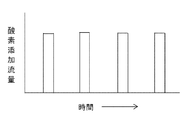
- FIG. 2 is a schematic diagram of an oxygen addition flow rate when oxygen is intermittently added according to the present invention.
- the addition flow rate must be sufficiently large with respect to the stoichiometric ratio, and must be less than the oxygen retention amount of the catalyst in order to prevent oxygen from flowing downstream of the catalyst tower. For this reason, it is necessary to investigate beforehand the relationship between the amount of catalyst and the amount of oxygen that can be retained. Note that if the amount of the catalyst is too small, the oxidation reaction may be insufficient or the oxygen addition interval may be too short to be realistic.
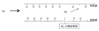
- FIG. 3 is a schematic diagram showing an image of the oxygen retention function on the catalyst surface estimated by the present inventors. Since it is unclear how oxygen is held on the catalyst surface, the held oxygen was temporarily expressed as the symbol “O”. The amount of oxygen added and injected intermittently should not exceed the amount of oxygen that can be held on the catalyst surface. Further, a hydrogen concentration meter and a carbon monoxide concentration meter (detection means) for monitoring (monitoring) surplus (unreacted) hydrogen and surplus (unreacted) carbon monoxide appearing on the outlet side of the catalyst tower are the catalyst tower. If installed in the middle of the catalyst, or installed in the middle of the catalyst tower in two stages, it is possible to cope with leakage of hydrogen components from the catalyst tower and the delay time of the concentration meter on the catalyst tower outlet side Become.
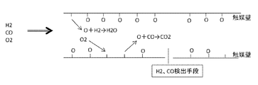
- FIG. 4 shows an image of the reaction between oxygen held on the catalyst surface and hydrogen and carbon monoxide in the argon gas when the argon gas contains hydrogen, carbon monoxide and oxygen, as estimated by the present inventors. It is a schematic diagram. Oxygen previously present in the argon gas is once held on the catalyst surface. And it reacts with hydrogen and carbon monoxide in argon gas like oxygen already held on the catalyst surface to produce water and carbon dioxide. 3 and 4 describe the estimations made by the present inventors in order to easily explain the phenomenon occurring in the catalyst tower. This estimation correctness does not affect the effectiveness of the present invention.
- FIG. 5 is a schematic diagram showing an example of the purification flow of waste argon gas from the silicon single crystal production apparatus according to the present invention, but is present in the waste argon gas recovery and purification apparatus according to the prior art (FIGS. 6 and 7). There is no need for a metal tower downstream of the catalyst tower.
- a portion surrounded by a broken line is a waste argon gas recovery and purification device.
- the waste argon gas discharged from the single crystal manufacturing apparatus is pressurized to a predetermined pressure by a pressurizing apparatus, and then sent to the waste argon gas recovery and purification apparatus 10.
- the apparatus for recovering and purifying waste argon gas comprises a catalyst tower for adding oxygen to argon gas and converting hydrogen and carbon monoxide contained in the argon gas into water and carbon dioxide by catalytic reaction, and the argon gas. 5 and at least one of catalytic towers that convert oxygen contained in the argon gas into water by catalytic reaction.
- oxygen is added to hydrogen and carbon monoxide to form water.
- the apparatus for recovering and purifying waste argon gas of the present invention is provided with detection means for monitoring at least one of hydrogen, carbon monoxide, and oxygen on the outlet side of the catalyst tower.
- the waste argon gas recovery and purification apparatus 10 shown in FIG. 5 includes a detection means for hydrogen and carbon monoxide.
- the waste argon gas recovery and purification apparatus of the present invention is an oxygen addition means for adding oxygen to the argon gas at the inlet side of the catalyst tower when either hydrogen or carbon monoxide is detected at the outlet side of the catalyst tower.
- the waste argon gas recovery and purification apparatus 10 shown in FIG. 5 shows an example including an oxygen addition means.
- the adsorption tower installed after the catalyst tower only needs to be able to adsorb and remove water, carbon dioxide, and nitrogen produced by the catalyst tower, and the same adsorption tower as before may be used.
- water and carbon dioxide are adsorbed and removed by the first adsorption tower in the same manner as the prior art shown in FIGS. Adsorb nitrogen.
- Patent Document 1 discloses zeolite and mordenite-type zeolite, and these can be used.
- the difference from the argon gas recovery and purification apparatus 10 shown in FIG. 5 is that a hydrogen addition means is provided in place of the oxygen addition means, and the gas to be detected is oxygen.
- oxygen When expressed in terms of molar equivalent, when the total amount of hydrogen and oxygen monoxide in the waste argon gas exceeds twice the molar equivalent ratio with respect to the amount of oxygen, oxygen is added by means of oxygen addition, In the case of less than 2 times, it can be paraphrased that hydrogen is added by a hydrogenation means.
- the concentration of impurities in the waste argon gas varies with time and it is necessary to change the gas to be added, it is preferable to provide both oxygen adding means and hydrogen adding means.
- oxygen or hydrogen in an amount equal to the stoichiometric amount of oxygen or hydrogen that is insufficient in the catalytic reaction in the catalytic tower is added during the time when oxygen and hydrogen are not added. Therefore, it is possible to prevent generation of excess oxygen and hydrogen.
- a similar purification method can be applied to oxygen contained in waste argon gas by monitoring the appearance of oxygen by changing the addition of oxygen to addition of hydrogen.
- the gas to be removed is hydrogen, carbon monoxide, and oxygen
- the magnitude relationship between the total amount of hydrogen and carbon monoxide and the amount of oxygen is often constant, and the smaller one is more catalyst. Since it is only used for the reaction, it is usually sufficient to install either oxygen adding means or hydrogen adding means.
- argon gas recovery and purification apparatus 10 The apparatus operating conditions of the argon gas recovery and purification apparatus 10 are shown below.
- -Waste argon gas flow rate 500 Nm 3 / h -Impurity concentration in waste argon gas
- Hydrogen 5-20 mol ppm
- Oxygen 20-30 mol ppm
- Carbon monoxide 60-100 mol ppm
- Nitrogen 50-100 mol ppm
- the waste argon gas was always stoichiometrically (total amount of hydrogen and carbon monoxide)> (oxygen amount).
- Catalyst Pt catalyst
- Additional gas Oxygen (4NL of oxygen is injected by one intermittent injection) The intermittent injection amount 4NL was obtained in advance by actually measuring the retention capacity of the catalyst.
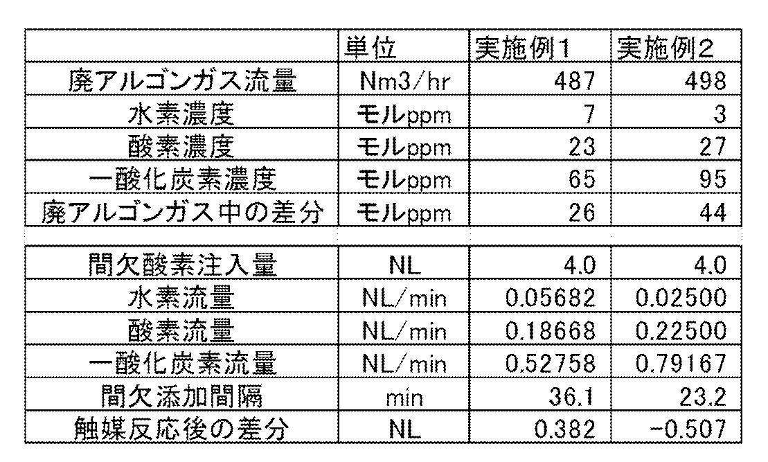
- Each concentration was converted into a flow rate by calculation with respect to the minimum (Min) value, average (Ave) value, and maximum (Max) value of the concentration of impurities (hydrogen, oxygen, carbon monoxide) in the waste argon gas.
- Table 1 shows the values and the results of calculating the intermittent addition interval using them. Further, when the waste argon gas flow rate is 487 Nm 3 / h, the hydrogen concentration is 7 mol ppm, the oxygen concentration is 23 mol ppm, and the oxygen monoxide concentration is 65 mol ppm (Example 1), the waste argon gas flow rate is 498 Nm 3.
- the “difference in waste argon gas” described in Table 1 is the concentration of gas remaining as a result of the catalytic reaction in the catalyst tower when no gas is added. Hydrogen and carbon monoxide can be handled in a total amount without distinction.
- the “intermittent addition interval” described in Table 1 is calculated by the following equation.
- Intermittent addition interval intermittent oxygen injection amount / ⁇ (1/2) ⁇ (hydrogen flow rate + carbon monoxide flow rate) ⁇ oxygen flow rate ⁇ (7)
- the impurity flow rate and the intermittent addition interval in other cases can be calculated in the same manner.
- the difference after the catalytic reaction total amount of surplus hydrogen and carbon monoxide, or surplus oxygen amount
- the argon gas recovery and purification apparatus and the argon gas purification method of the present invention recover and purify argon gas as furnace atmosphere gas in a silicon single crystal manufacturing apparatus (CZ apparatus, FZ apparatus). It is intended to be reused, and it is possible to reduce the cost of the recovery and purification apparatus, to stably operate the apparatus, and to contribute to energy saving.
- the present invention is not limited to the above embodiment.
- the above-described embodiment is an exemplification, and the present invention has substantially the same configuration as the technical idea described in the claims of the present invention, and any device that exhibits the same function and effect is the present invention. It is included in the technical scope of the invention.
Landscapes
- Chemical & Material Sciences (AREA)
- Organic Chemistry (AREA)
- Chemical Kinetics & Catalysis (AREA)
- General Chemical & Material Sciences (AREA)
- Analytical Chemistry (AREA)
- Inorganic Chemistry (AREA)
- Engineering & Computer Science (AREA)
- Crystallography & Structural Chemistry (AREA)
- Materials Engineering (AREA)
- Metallurgy (AREA)
- Catalysts (AREA)
- Crystals, And After-Treatments Of Crystals (AREA)
Abstract
Description
H2 + (1/2)O2 → H2O (1)
CO + (1/2)O2 → CO2 (2)
この反応により、廃アルゴンガス中に含まれる水素、酸素、一酸化炭素を全て水と二酸化炭素に転換し、触媒反応工程より後段に水素、酸素、一酸化炭素が残らないようにするためには、この化学式の化学量論比の通り過不足なく水素、酸素を添加する必要がある。
H2 + CuO → H2O + Cu (3)
CO + CuO → CO2 + Cu (4)
O2 + 金属 → 金属酸化物 (5)
A=500Nm3/h×100モルppm×1/2=0.025Nm3/h
=0.417NL/min
B=500Nm3/h×1モルppm×1/2=0.00417NL/min
このことは、触媒反応後の酸素濃度を1モルppm以下になるようにするためには、廃アルゴンガス中の水素濃度の変動に対して、添加する酸素の量を0.00417NL/min以下の精度で常時過不足なく制御する必要があることを意味している。これは技術的に非常に困難である。
前記触媒塔の出口側で水素、一酸化炭素、及び酸素の少なくともいずれか一つをモニターする工程と、
前記触媒塔の出口側で水素及び一酸化酸素のいずれかが検出された場合には前記触媒塔の入口側で前記アルゴンガスに酸素を添加する工程と、前記触媒塔の出口側で酸素が検出された場合には前記触媒塔の入口側で前記アルゴンガスに水素を添加する工程の少なくともいずれかを有し、
前記アルゴンガスが前記触媒塔に連続的に供給されるのに対して、前記触媒塔に添加される酸素又は水素の添加を間欠的に行うことにより前記アルゴンガスに含まれる水素、一酸化炭素、及び酸素のうちいずれか一つ以上を除去することを特徴とするアルゴンガスの精製方法を提供する。
このように余剰酸素を金属との酸化反応で除去する工程、及び余剰水素を金属との還元反応で除去する工程を有さなければ、触媒塔の下流側の金属塔が不要であり、設備構成が簡単になり、設備コストを安くすることができるとともに、金属塔における金属の酸化還元による再生が不要であり、金属塔に起因する設備故障の発生もなくすことができる。また、エネルギー消費量も少なくすることができる。
このように精製されるアルゴンガスに含有される水素と一酸化炭素の合計量と酸素の量を比較することで、添加するガスを酸素とするか、又は水素とするかをあらかじめ決定できるので、一種類の触媒塔のみを有する精製装置でアルゴンガスを精製することができる。
このように、シリコン単結晶製造装置から排出される廃アルゴンガスを上記方法により精製することにより、シリコン単結晶製造装置の運転コストを低く抑えることができる。
このように触媒反応で不足する化学量論量の水素又は酸素を添加することで、余剰の酸素及び水素が発生しないようにすることができる。
前記アルゴンガスに酸素を添加して、前記アルゴンガスに含有される水素と一酸化炭素を触媒反応により水と二酸化炭素に転換する触媒塔、及び前記アルゴンガスに水素を添加して、前記アルゴンガスに含有される酸素を触媒反応により水に転換する触媒塔の少なくともいずれかと、
前記触媒塔の出口側で水素、一酸化炭素、及び酸素の少なくともいずれか一つをモニターする検出手段と、
前記触媒塔の出口側で水素及び一酸化炭素のいずれかが検出された場合に前記触媒塔の入口側で前記アルゴンガスに酸素を添加する酸素添加手段、及び前記触媒塔の出口側で酸素が検出された場合に前記触媒塔の入口側で前記アルゴンガスに水素を添加する水素添加手段の少なくともいずれかを有し、
前記酸素添加手段及び前記水素添加手段は、前記アルゴンガスが連続的に前記触媒塔に供給されるのに対して、酸素又は水素を間欠的に添加するものであることを特徴とするアルゴンガスの回収精製装置を提供する。
このように金属塔を有さないアルゴンガスの回収精製装置であれば、設備構成が簡単になり、設備コストを安くすることができるとともに、金属塔における金属の酸化還元による再生が不要であり、金属塔に起因する設備故障の発生もなくすことができる。また、エネルギー消費量も少なくすることができる。
このように精製されるアルゴンガスに含有される水素と一酸化炭素の合計量と酸素の量を比較することで、添加するガスを酸素とするか、又は水素とするかをあらかじめ決定できるので、一種類の触媒塔のみを有するアルゴンガスの回収精製装置とすることもできる。
このように、シリコン単結晶製造装置から排出される廃アルゴンガスを上記アルゴンガスの回収精製装置で精製することにより、シリコン単結晶製造装置の運転コストを低く抑えることができる。
このように触媒反応で不足する化学量論量の水素又は酸素を添加することで、余剰の酸素及び水素が発生しないようにすることができる。
本発明者らは、シリコン単結晶製造装置などの廃アルゴンガスの精製にあたって、廃アルゴンガス中の水素、酸素、一酸化炭素不純物に水素、酸素を添加して触媒反応を行う時に、添加した水素、酸素量と触媒塔から出てくる余剰水素、余剰酸素の量に時間のズレがあることに注目した。
アルゴンガスの回収精製装置について、以下に図1から図5を参照して説明する。
図1は、廃アルゴンガスに酸素を添加し触媒反応させることを示す模式図であり、触媒塔の入口側で酸素を添加・注入する場合の図である。廃アルゴンガスは、水素、一酸化炭素、及び酸素の少なくとも一つ以上を不純物として含有している。この場合、間欠的に酸素を添加・注入することによって、添加された酸素が触媒の表面に到達するまの間に十分均一に廃アルゴンガスに混合されている必要がある。
図2は、本発明により酸素を間欠的に添加する場合の酸素添加流量の模式図である。添加流量は化学量論比に対して十分大きくとる必要があり、かつ触媒塔の下流に酸素が流れ出さないようにするために、触媒の酸素保持量を下回る量でなければならない。このため、触媒の量と酸素保持可能量の関係をあらかじめテストすることにより調べておく必要がある。触媒の量が少なすぎると、酸化反応が不十分になったり、酸素添加間隔が短すぎて現実的にならないことがあるので注意を要する。
尚、図3及び図4による説明は触媒塔内で起こる現象を解りやすく解説するための本発明者らの推定を記したものである。この推定の正誤は本発明の有効性に影響を与えるものではない。
尚、モル当量で表した場合には、廃アルゴンガス中の水素と一酸化酸素の合計量が酸素の量に対してモル当量比で2倍を超える場合は酸素添加手段により酸素を添加し、2倍未満の場合は水素添加手段により水素を添加すると言い換えることができる。
また、廃アルゴンガス中の不純物の濃度が経時的に変動し、添加するガスを変更する必要がある場合には、酸素添加手段と水素添加手段の両方を備えるようにするのが好ましい。
図5に示したアルゴンガスの回収精製装置を用いたアルゴンガスの精製方法について以下に説明する。
まず、図1に示すような廃アルゴンガスの精製において、水素、一酸化炭素を添加酸素により触媒塔を用いて水、及び二酸化炭素に転換する場合、添加酸素を化学量論比に対して過剰に短時間(ピーク的に)添加・注入して触媒塔の中に酸素を保持させる。触媒塔の出口側では、水素及び一酸化炭素が継続的にモニターされる。その後、触媒塔の出口側に水素又は一酸化炭素が出現するまでの間は、水素、一酸化炭素は触媒塔内に保持された酸素と反応し水、二酸化炭素が生成されている。そして、触媒塔の出口側で水素又は一酸化炭素が検出されたら、再び、化学量論比に対して過剰の酸素を触媒塔に注入(添加)する操作を行う。この状況は図2に示すように、過剰の酸素の短時間注入を間欠的に行うことにより、全体としては化学量論量の酸素を添加することを意味し、廃アルゴンガスの精製を継続的に進めることができることになる。
(実施例)
シリコン単結晶製造装置(CZ装置)からの廃アルゴンガスを本発明のアルゴンガスの回収精製装置及びアルゴンガスの精製方法により精製した(図5に示した精製フローによる)。
・廃アルゴンガス流量: 500Nm3/h
・廃アルゴンガス中の不純物濃度
水素: 5~20モルppm
酸素: 20~30モルppm
一酸化炭素: 60~100モルppm
窒素: 50~100モルppm
尚、この廃アルゴンガスは常に、化学量論的に(水素と一酸化炭素の合計量)>(酸素量)であった。
・触媒: Pt触媒
・添加ガス: 酸素(1回の間欠注入にて4NLの酸素を注入)
間欠注入量4NLはあらかじめ触媒の保持能力を実測して求めた。

水素の濃度は5モルppmであるから、流量は0.04167NL/min(=500Nm3/h×5モルppm=0.0025Nm3/h=0.04167NL/min)となる。
同様の計算により、酸素の濃度は20モルppmであるから、流量は0.16667NL/min、一酸化炭素の濃度は60モルppmであるから、流量は0.50000NL/minとなる。
廃アルゴンガス中の差分=水素濃度+一酸化炭素濃度―2×酸素濃度 (6)
濃度の最小値の場合では、(6)式に従い、廃アルゴンガス中の差分は25モルppm(=5+60-2×20)となる。
間欠添加間隔=間欠酸素注入量÷{(1/2)×(水素流量+一酸化炭素流量)-酸素流量} (7)
濃度の最小値の場合では、(7)式に従い、間欠添加間隔は38.4min(=4÷{0.5×(0.04167+0.50000)-0.16667})となる。他のケースの不純物の流量及び間欠添加間隔についても、同様にして計算することができる。
表1に記載した全ての計算結果において、触媒反応後の差分(余剰の水素と一酸化炭素の合計量、又は余剰の酸素量)はゼロとなる。
・精製されたアルゴンガス中の不純物濃度
水素 ≦1モルppm
酸素 ≦1モルppm
一酸化炭素 ≦1モルppm
二酸化炭素 ≦1モルppm
窒素 ≦2モルppm
このように、精製されたアルゴンガスはシリコン単結晶製造装置において再利用するために十分な純度を有するものであった。
Claims (10)
- 水素、一酸化炭素、及び酸素の少なくともいずれか一つ以上を不純物として含有するアルゴンガスに、酸素を添加して触媒塔において触媒反応を用いて前記アルゴンガスに含有される水素と一酸化炭素を水と二酸化炭素に転換するか、又は水素を添加して前記触媒塔において触媒反応を用いて前記アルゴンガスに含有される酸素を水に転換することにより、前記アルゴンガスから水素、一酸化炭素、及び酸素の少なくともいずれか一つ以上を除去するアルゴンガスの精製方法であって、
前記触媒塔の出口側で水素、一酸化炭素、及び酸素の少なくともいずれか一つをモニターする工程と、
前記触媒塔の出口側で水素及び一酸化酸素のいずれかが検出された場合には前記触媒塔の入口側で前記アルゴンガスに酸素を添加する工程と、前記触媒塔の出口側で酸素が検出された場合には前記触媒塔の入口側で前記アルゴンガスに水素を添加する工程の少なくともいずれかを有し、
前記アルゴンガスが前記触媒塔に連続的に供給されるのに対して、前記触媒塔に添加される酸素又は水素の添加を間欠的に行うことにより前記アルゴンガスに含まれる水素、一酸化炭素、及び酸素のうちいずれか一つ以上を除去することを特徴とするアルゴンガスの精製方法。 - 前記触媒塔の下流において、前記触媒反応で余剰となった酸素を金属との酸化反応により除去する工程、及び前記触媒反応で余剰となった水素を金属との還元反応により除去する工程を有さないことを特徴とする請求項1に記載のアルゴンガスの精製方法。
- 前記精製されるアルゴンガスに含有される水素と一酸化炭素の合計量と酸素の量を比較し、前記水素と一酸化酸素の合計量が前記酸素の量に対してモル当量比で2倍を超える場合は添加するガスを酸素とし、2倍未満の場合は添加するガスを水素とすることを特徴とする請求項1又は請求項2に記載のアルゴンガスの精製方法。
- 前記精製されるアルゴンガスを、シリコン単結晶製造装置から排出される廃アルゴンガスとすることを特徴とする請求項1から請求項3のいずれか一項に記載のアルゴンガスの精製方法。
- 前記間欠的に添加する酸素又は水素の量を、酸素及び水素を添加しなかった時間に、前記触媒反応で不足する酸素又は水素の化学量論量と等しくすることを特徴とする請求項1から請求項4のいずれか一項に記載のアルゴンガスの精製方法。
- 水素、一酸化炭素、及び酸素の少なくとも一つ以上を不純物として含有するアルゴンガスの回収精製装置であって、
前記アルゴンガスに酸素を添加して、前記アルゴンガスに含有される水素と一酸化炭素を触媒反応により水と二酸化炭素に転換する触媒塔、及び前記アルゴンガスに水素を添加して、前記アルゴンガスに含有される酸素を触媒反応により水に転換する触媒塔の少なくともいずれかと、
前記触媒塔の出口側で水素、一酸化炭素、及び酸素の少なくともいずれか一つをモニターする検出手段と、
前記触媒塔の出口側で水素及び一酸化炭素のいずれかが検出された場合に前記触媒塔の入口側で前記アルゴンガスに酸素を添加する酸素添加手段、及び前記触媒塔の出口側で酸素が検出された場合に前記触媒塔の入口側で前記アルゴンガスに水素を添加する水素添加手段の少なくともいずれかを有し、
前記酸素添加手段及び前記水素添加手段は、前記アルゴンガスが連続的に前記触媒塔に供給されるのに対して、酸素又は水素を間欠的に添加するものであることを特徴とするアルゴンガスの回収精製装置。 - 前記触媒塔の下流において前記触媒反応で余剰となった酸素を金属との酸化反応で除去する金属塔、及び前記触媒反応で余剰となった水素を金属との還元反応で除去する金属塔を有さないものであることを特徴とする請求項6に記載のアルゴンガスの回収精製装置。
- 前記精製されるアルゴンガスに含有される水素と一酸化炭素の合計量と酸素の量を比較し、前記水素と一酸化酸素の合計量が前記酸素の量に対してモル当量比で2倍を超える場合は酸素を添加し、2倍未満の場合は水素を添加するものであることを特徴とする請求項6又は請求項7に記載のアルゴンガスの回収精製装置。
- 前記精製されるアルゴンガスが、シリコン単結晶製造装置から排出される廃アルゴンガスであることを特徴とする請求項6から請求項8のいずれか一項に記載のアルゴンガスの回収精製装置。
- 前記間欠的に添加する酸素又は水素の量が、酸素及び水素を添加しなかった時間に、前記触媒反応で不足する酸素又は水素の化学量論量と等しくするものであることを特徴とする請求項6から請求項9のいずれか一項に記載のアルゴンガスの回収精製装置。
Priority Applications (4)
| Application Number | Priority Date | Filing Date | Title |
|---|---|---|---|
| CN201680016958.7A CN107428532B (zh) | 2015-03-24 | 2016-02-24 | 氩气的纯化方法以及氩气的回收纯化装置 |
| US15/557,677 US11305994B2 (en) | 2015-03-24 | 2016-02-24 | Method for refining argon gas and recovering and refining apparatus for argon gas |
| KR1020177026337A KR102508050B1 (ko) | 2015-03-24 | 2016-02-24 | 아르곤가스의 정제방법 및 아르곤가스의 회수정제장치 |
| DE112016000984.4T DE112016000984T5 (de) | 2015-03-24 | 2016-02-24 | Verfahren zur Raffination von Argongas und Rückgewinnungs-und Raffinationsvorrichtung für Argongas |
Applications Claiming Priority (2)
| Application Number | Priority Date | Filing Date | Title |
|---|---|---|---|
| JP2015-060405 | 2015-03-24 | ||
| JP2015060405A JP6304089B2 (ja) | 2015-03-24 | 2015-03-24 | アルゴンガスの精製方法及びアルゴンガスの回収精製装置 |
Publications (1)
| Publication Number | Publication Date |
|---|---|
| WO2016152027A1 true WO2016152027A1 (ja) | 2016-09-29 |
Family
ID=56977210
Family Applications (1)
| Application Number | Title | Priority Date | Filing Date |
|---|---|---|---|
| PCT/JP2016/000988 Ceased WO2016152027A1 (ja) | 2015-03-24 | 2016-02-24 | アルゴンガスの精製方法及びアルゴンガスの回収精製装置 |
Country Status (6)
| Country | Link |
|---|---|
| US (1) | US11305994B2 (ja) |
| JP (1) | JP6304089B2 (ja) |
| KR (1) | KR102508050B1 (ja) |
| CN (1) | CN107428532B (ja) |
| DE (1) | DE112016000984T5 (ja) |
| WO (1) | WO2016152027A1 (ja) |
Families Citing this family (6)
| Publication number | Priority date | Publication date | Assignee | Title |
|---|---|---|---|---|
| CN108310456B (zh) * | 2018-04-13 | 2020-04-07 | 昆明理工大学 | 一种氧化石墨烯/纳米羟基磷灰石复合硅胶改性多孔支架材料的制备方法 |
| CN108745370B (zh) * | 2018-05-25 | 2020-11-03 | 兰州大学 | 一种用于纯化单晶炉工业氩气尾气的催化剂及制备方法 |
| CN109930201A (zh) * | 2019-03-08 | 2019-06-25 | 银川隆基硅材料有限公司 | 一种气体回用控制方法及气体回用控制设备 |
| WO2020241654A1 (ja) | 2019-05-28 | 2020-12-03 | 株式会社トクヤマ | 炭酸ガス、およびその他ガスの回収方法 |
| CN115236219A (zh) * | 2022-06-22 | 2022-10-25 | 华能海南昌江核电有限公司 | 一种高温气冷堆氦气中氧气含量测定装置及其测定方法 |
| KR102736660B1 (ko) | 2023-04-07 | 2024-12-02 | (주)오디씨티 | 벌크가스 정제용 게터 및 이를 이용하는 게터 타입 벌크가스 정제시스템 |
Citations (6)
| Publication number | Priority date | Publication date | Assignee | Title |
|---|---|---|---|---|
| JPH02282682A (ja) * | 1989-04-21 | 1990-11-20 | Nippon Sanso Kk | アルゴンの回収方法 |
| JP2011173769A (ja) * | 2010-02-25 | 2011-09-08 | Sumitomo Seika Chem Co Ltd | アルゴンガスの精製方法および精製装置 |
| JP2011184287A (ja) * | 2010-02-10 | 2011-09-22 | Sumitomo Seika Chem Co Ltd | アルゴンガスの精製方法および精製装置 |
| JP2012106904A (ja) * | 2010-10-29 | 2012-06-07 | Sumitomo Seika Chem Co Ltd | アルゴンガスの精製方法および精製装置 |
| JP2013155091A (ja) * | 2012-01-31 | 2013-08-15 | Sumitomo Seika Chem Co Ltd | アルゴンガスの精製方法および精製装置 |
| JP2014034493A (ja) * | 2012-08-09 | 2014-02-24 | Sumitomo Seika Chem Co Ltd | アルゴンガスの精製方法および精製装置 |
Family Cites Families (7)
| Publication number | Priority date | Publication date | Assignee | Title |
|---|---|---|---|---|
| JPS5939800A (ja) * | 1982-08-28 | 1984-03-05 | Kyodo Sanso Kk | 半導体用単結晶製造炉における雰囲気用アルゴン回収方法 |
| JPS5946473A (ja) * | 1982-09-10 | 1984-03-15 | 共同酸素株式会社 | 半導体用単結晶製造炉における雰囲気用アルゴン回収方法 |
| JPH0624962B2 (ja) | 1985-11-15 | 1994-04-06 | 日本酸素株式会社 | 単結晶製造炉の排ガスより高純度アルゴンを回収する方法 |
| JP5566815B2 (ja) * | 2010-08-31 | 2014-08-06 | 大陽日酸株式会社 | ガスの精製方法およびガス精製装置 |
| KR20120046008A (ko) * | 2010-10-29 | 2012-05-09 | 스미또모 세이까 가부시키가이샤 | 아르곤 가스의 정제 방법 및 정제 장치 |
| JP5791113B2 (ja) * | 2011-04-12 | 2015-10-07 | 住友精化株式会社 | アルゴンガスの精製方法および精製装置 |
| CN103373716B (zh) * | 2013-07-15 | 2015-01-07 | 杭州杭氧股份有限公司 | 一种单晶硅制备工艺中排放氩气的净化回收方法与装置 |
-
2015
- 2015-03-24 JP JP2015060405A patent/JP6304089B2/ja active Active
-
2016
- 2016-02-24 DE DE112016000984.4T patent/DE112016000984T5/de active Pending
- 2016-02-24 WO PCT/JP2016/000988 patent/WO2016152027A1/ja not_active Ceased
- 2016-02-24 US US15/557,677 patent/US11305994B2/en active Active
- 2016-02-24 CN CN201680016958.7A patent/CN107428532B/zh active Active
- 2016-02-24 KR KR1020177026337A patent/KR102508050B1/ko active Active
Patent Citations (6)
| Publication number | Priority date | Publication date | Assignee | Title |
|---|---|---|---|---|
| JPH02282682A (ja) * | 1989-04-21 | 1990-11-20 | Nippon Sanso Kk | アルゴンの回収方法 |
| JP2011184287A (ja) * | 2010-02-10 | 2011-09-22 | Sumitomo Seika Chem Co Ltd | アルゴンガスの精製方法および精製装置 |
| JP2011173769A (ja) * | 2010-02-25 | 2011-09-08 | Sumitomo Seika Chem Co Ltd | アルゴンガスの精製方法および精製装置 |
| JP2012106904A (ja) * | 2010-10-29 | 2012-06-07 | Sumitomo Seika Chem Co Ltd | アルゴンガスの精製方法および精製装置 |
| JP2013155091A (ja) * | 2012-01-31 | 2013-08-15 | Sumitomo Seika Chem Co Ltd | アルゴンガスの精製方法および精製装置 |
| JP2014034493A (ja) * | 2012-08-09 | 2014-02-24 | Sumitomo Seika Chem Co Ltd | アルゴンガスの精製方法および精製装置 |
Also Published As
| Publication number | Publication date |
|---|---|
| DE112016000984T5 (de) | 2018-01-04 |
| KR102508050B1 (ko) | 2023-03-09 |
| US20180050912A1 (en) | 2018-02-22 |
| CN107428532A (zh) | 2017-12-01 |
| JP2016179916A (ja) | 2016-10-13 |
| US11305994B2 (en) | 2022-04-19 |
| KR20170130412A (ko) | 2017-11-28 |
| CN107428532B (zh) | 2020-09-29 |
| JP6304089B2 (ja) | 2018-04-04 |
Similar Documents
| Publication | Publication Date | Title |
|---|---|---|
| JP6304089B2 (ja) | アルゴンガスの精製方法及びアルゴンガスの回収精製装置 | |
| JP7319965B2 (ja) | 自己熱アンモニア分解方法 | |
| US8685236B2 (en) | Methods and systems for treating sour water | |
| EP0241910B1 (en) | Process for separating carbon monoxide having substantially constant purity | |
| RU2527991C1 (ru) | Способ непрерывного удаления сернистого водорода из потока газа | |
| CA2856293C (en) | Direct reduced iron manufacturing system | |
| JP2018505958A (ja) | 超高純度一酸化炭素の製造方法 | |
| US20160074804A1 (en) | Absorption medium, process for producing an absorption medium, and also process and apparatus for separating hydrogen sulfide from an acidic gas | |
| JP2016179916A5 (ja) | ||
| EA022555B1 (ru) | Интегрированный способ обработки сточных вод нефтеперегонного завода, содержащих аммиак и сероводород, и отводимых кислых газов нефтеперегонного завода, содержащих сероводород | |
| JP2008168169A (ja) | ネオン回収方法 | |
| US7384611B2 (en) | Configurations and methods for effluent gas treatment | |
| CN108136328A (zh) | 纯化co2流的方法 | |
| JP2003246611A (ja) | ヘリウム精製装置 | |
| JP2020066585A (ja) | 有機物の合成装置および合成方法 | |
| WO2012139763A1 (de) | Verfahren und anlage zur abreicherung von stickoxiden aus sauerstoffhaltigen gasströmen | |
| CN101987726A (zh) | 气体纯化装置 | |
| US20200063055A1 (en) | Method and device for the desulphurisation of a gas stream containing hydrogen sulphide | |
| JP3858359B2 (ja) | 有機物の除去方法 | |
| JP4382770B2 (ja) | 二酸化炭素の精製方法 | |
| CN103359696B (zh) | 一种连续生产羟铵的方法 | |
| JPH1025102A (ja) | 圧力スイング吸着法における塩素の除去装置及び酸素の分離方法 | |
| CN103359697B (zh) | 一种连续生产羟铵的方法 | |
| EP3484813B1 (en) | Selective oxidation of hydrogen sulfide | |
| JP2017206402A (ja) | 水素ガスの製造方法、およびバイオガス水素化設備 |
Legal Events
| Date | Code | Title | Description |
|---|---|---|---|
| 121 | Ep: the epo has been informed by wipo that ep was designated in this application |
Ref document number: 16767939 Country of ref document: EP Kind code of ref document: A1 |
|
| WWE | Wipo information: entry into national phase |
Ref document number: 15557677 Country of ref document: US |
|
| ENP | Entry into the national phase |
Ref document number: 20177026337 Country of ref document: KR Kind code of ref document: A |
|
| WWE | Wipo information: entry into national phase |
Ref document number: 112016000984 Country of ref document: DE |
|
| 122 | Ep: pct application non-entry in european phase |
Ref document number: 16767939 Country of ref document: EP Kind code of ref document: A1 |