WO2016147606A1 - 変速装置及びそれを備える発電システム - Google Patents
変速装置及びそれを備える発電システム Download PDFInfo
- Publication number
- WO2016147606A1 WO2016147606A1 PCT/JP2016/001260 JP2016001260W WO2016147606A1 WO 2016147606 A1 WO2016147606 A1 WO 2016147606A1 JP 2016001260 W JP2016001260 W JP 2016001260W WO 2016147606 A1 WO2016147606 A1 WO 2016147606A1
- Authority
- WO
- WIPO (PCT)
- Prior art keywords
- chamber
- pressure oil
- speed
- deceleration
- trunnion
- Prior art date
- Legal status (The legal status is an assumption and is not a legal conclusion. Google has not performed a legal analysis and makes no representation as to the accuracy of the status listed.)
- Ceased
Links
Images

Classifications
-
- F—MECHANICAL ENGINEERING; LIGHTING; HEATING; WEAPONS; BLASTING
- F16—ENGINEERING ELEMENTS AND UNITS; GENERAL MEASURES FOR PRODUCING AND MAINTAINING EFFECTIVE FUNCTIONING OF MACHINES OR INSTALLATIONS; THERMAL INSULATION IN GENERAL
- F16H—GEARING
- F16H15/00—Gearings for conveying rotary motion with variable gear ratio, or for reversing rotary motion, by friction between rotary members
- F16H15/02—Gearings for conveying rotary motion with variable gear ratio, or for reversing rotary motion, by friction between rotary members without members having orbital motion
- F16H15/04—Gearings providing a continuous range of gear ratios
- F16H15/06—Gearings providing a continuous range of gear ratios in which a member A of uniform effective diameter mounted on a shaft may co-operate with different parts of a member B
- F16H15/32—Gearings providing a continuous range of gear ratios in which a member A of uniform effective diameter mounted on a shaft may co-operate with different parts of a member B in which the member B has a curved friction surface formed as a surface of a body of revolution generated by a curve which is neither a circular arc centered on its axis of revolution nor a straight line
- F16H15/36—Gearings providing a continuous range of gear ratios in which a member A of uniform effective diameter mounted on a shaft may co-operate with different parts of a member B in which the member B has a curved friction surface formed as a surface of a body of revolution generated by a curve which is neither a circular arc centered on its axis of revolution nor a straight line with concave friction surface, e.g. a hollow toroid surface
- F16H15/38—Gearings providing a continuous range of gear ratios in which a member A of uniform effective diameter mounted on a shaft may co-operate with different parts of a member B in which the member B has a curved friction surface formed as a surface of a body of revolution generated by a curve which is neither a circular arc centered on its axis of revolution nor a straight line with concave friction surface, e.g. a hollow toroid surface with two members B having hollow toroid surfaces opposite to each other, the member or members A being adjustably mounted between the surfaces
-
- H—ELECTRICITY
- H02—GENERATION; CONVERSION OR DISTRIBUTION OF ELECTRIC POWER
- H02K—DYNAMO-ELECTRIC MACHINES
- H02K7/00—Arrangements for handling mechanical energy structurally associated with dynamo-electric machines, e.g. structural association with mechanical driving motors or auxiliary dynamo-electric machines
- H02K7/10—Structural association with clutches, brakes, gears, pulleys or mechanical starters
- H02K7/116—Structural association with clutches, brakes, gears, pulleys or mechanical starters with gears
-
- B—PERFORMING OPERATIONS; TRANSPORTING
- B62—LAND VEHICLES FOR TRAVELLING OTHERWISE THAN ON RAILS
- B62M—RIDER PROPULSION OF WHEELED VEHICLES OR SLEDGES; POWERED PROPULSION OF SLEDGES OR SINGLE-TRACK CYCLES; TRANSMISSIONS SPECIALLY ADAPTED FOR SUCH VEHICLES
- B62M11/00—Transmissions characterised by the use of interengaging toothed wheels or frictionally-engaging wheels
- B62M11/04—Transmissions characterised by the use of interengaging toothed wheels or frictionally-engaging wheels of changeable ratio
- B62M11/12—Transmissions characterised by the use of interengaging toothed wheels or frictionally-engaging wheels of changeable ratio with frictionally-engaging wheels
-
- F—MECHANICAL ENGINEERING; LIGHTING; HEATING; WEAPONS; BLASTING
- F16—ENGINEERING ELEMENTS AND UNITS; GENERAL MEASURES FOR PRODUCING AND MAINTAINING EFFECTIVE FUNCTIONING OF MACHINES OR INSTALLATIONS; THERMAL INSULATION IN GENERAL
- F16H—GEARING
- F16H15/00—Gearings for conveying rotary motion with variable gear ratio, or for reversing rotary motion, by friction between rotary members
- F16H15/48—Gearings for conveying rotary motion with variable gear ratio, or for reversing rotary motion, by friction between rotary members with members having orbital motion
- F16H15/50—Gearings providing a continuous range of gear ratios
- F16H15/52—Gearings providing a continuous range of gear ratios in which a member of uniform effective diameter mounted on a shaft may co-operate with different parts of another member
-
- F—MECHANICAL ENGINEERING; LIGHTING; HEATING; WEAPONS; BLASTING
- F16—ENGINEERING ELEMENTS AND UNITS; GENERAL MEASURES FOR PRODUCING AND MAINTAINING EFFECTIVE FUNCTIONING OF MACHINES OR INSTALLATIONS; THERMAL INSULATION IN GENERAL
- F16H—GEARING
- F16H61/00—Control functions within control units of change-speed- or reversing-gearings for conveying rotary motion ; Control of exclusively fluid gearing, friction gearing, gearings with endless flexible members or other particular types of gearing
- F16H61/02—Control functions within control units of change-speed- or reversing-gearings for conveying rotary motion ; Control of exclusively fluid gearing, friction gearing, gearings with endless flexible members or other particular types of gearing characterised by the signals used
- F16H61/0202—Control functions within control units of change-speed- or reversing-gearings for conveying rotary motion ; Control of exclusively fluid gearing, friction gearing, gearings with endless flexible members or other particular types of gearing characterised by the signals used the signals being electric
- F16H61/0251—Elements specially adapted for electric control units, e.g. valves for converting electrical signals to fluid signals
-
- F—MECHANICAL ENGINEERING; LIGHTING; HEATING; WEAPONS; BLASTING
- F16—ENGINEERING ELEMENTS AND UNITS; GENERAL MEASURES FOR PRODUCING AND MAINTAINING EFFECTIVE FUNCTIONING OF MACHINES OR INSTALLATIONS; THERMAL INSULATION IN GENERAL
- F16H—GEARING
- F16H61/00—Control functions within control units of change-speed- or reversing-gearings for conveying rotary motion ; Control of exclusively fluid gearing, friction gearing, gearings with endless flexible members or other particular types of gearing
- F16H61/26—Generation or transmission of movements for final actuating mechanisms
- F16H61/28—Generation or transmission of movements for final actuating mechanisms with at least one movement of the final actuating mechanism being caused by a non-mechanical force, e.g. power-assisted
- F16H61/2807—Generation or transmission of movements for final actuating mechanisms with at least one movement of the final actuating mechanism being caused by a non-mechanical force, e.g. power-assisted using electric control signals for shift actuators, e.g. electro-hydraulic control therefor
-
- F—MECHANICAL ENGINEERING; LIGHTING; HEATING; WEAPONS; BLASTING
- F16—ENGINEERING ELEMENTS AND UNITS; GENERAL MEASURES FOR PRODUCING AND MAINTAINING EFFECTIVE FUNCTIONING OF MACHINES OR INSTALLATIONS; THERMAL INSULATION IN GENERAL
- F16H—GEARING
- F16H61/00—Control functions within control units of change-speed- or reversing-gearings for conveying rotary motion ; Control of exclusively fluid gearing, friction gearing, gearings with endless flexible members or other particular types of gearing
- F16H61/66—Control functions within control units of change-speed- or reversing-gearings for conveying rotary motion ; Control of exclusively fluid gearing, friction gearing, gearings with endless flexible members or other particular types of gearing specially adapted for continuously variable gearings
- F16H61/664—Friction gearings
-
- H—ELECTRICITY
- H02—GENERATION; CONVERSION OR DISTRIBUTION OF ELECTRIC POWER
- H02K—DYNAMO-ELECTRIC MACHINES
- H02K7/00—Arrangements for handling mechanical energy structurally associated with dynamo-electric machines, e.g. structural association with mechanical driving motors or auxiliary dynamo-electric machines
- H02K7/10—Structural association with clutches, brakes, gears, pulleys or mechanical starters
-
- H—ELECTRICITY
- H02—GENERATION; CONVERSION OR DISTRIBUTION OF ELECTRIC POWER
- H02K—DYNAMO-ELECTRIC MACHINES
- H02K7/00—Arrangements for handling mechanical energy structurally associated with dynamo-electric machines, e.g. structural association with mechanical driving motors or auxiliary dynamo-electric machines
- H02K7/18—Structural association of electric generators with mechanical driving motors, e.g. with turbines
- H02K7/1807—Rotary generators
-
- F—MECHANICAL ENGINEERING; LIGHTING; HEATING; WEAPONS; BLASTING
- F16—ENGINEERING ELEMENTS AND UNITS; GENERAL MEASURES FOR PRODUCING AND MAINTAINING EFFECTIVE FUNCTIONING OF MACHINES OR INSTALLATIONS; THERMAL INSULATION IN GENERAL
- F16H—GEARING
- F16H2302/00—Determining the way or trajectory to new ratio, e.g. by determining speed, torque or time parameters for shift transition
- F16H2302/04—Determining a modus for shifting
Definitions
- the present invention relates to a transmission having a toroidal continuously variable transmission and a power generation system including the same.
- a transmission control device for a toroidal continuously variable transmission as disclosed in Patent Document 1 is known as a transmission device that increases or decreases the rotational driving force on the input shaft side and transmits it to the output side.
- the speed ratio is changed steplessly by tilting the power roller sandwiched between the input disk and the output disk.
- the power roller is tiltably supported by a trunnion, and the power roller is tilted when the trunnion is displaced in the tilt axis direction.
- the trunnion is provided with a hydraulically driven cylinder mechanism, and the cylinder mechanism is configured to move the trunnion in the direction of the tilt axis by advancing and retracting the piston when pressure oil is supplied.
- the piston is provided with a hydraulic drive device including a spool valve and a pump.
- the hydraulic drive device supplies pressure oil discharged from the pump to the cylinder mechanism, and switches the flow direction of the pressure oil supplied to the cylinder mechanism by a spool valve.
- the cylinder mechanism advances and retracts the piston according to the direction in which the pressure oil supplied thereto flows. As a result, the power roller is tilted, and the rotational driving force on the input shaft side is increased or decreased according to the tilt angle of the power roller.
- the spool valve has a casing and a spool, and the spool slides in the casing. Pilot pressure acts on both ends of the spool so as to resist each other, and the spool moves to a position corresponding to the differential pressure between the two pilot pressures.
- the spool valve flows pressure oil in a direction corresponding to the position of the spool.
- the flowing pressure oil may contain foreign matter such as metal powder, and the foreign matter may enter the space between the spool and the casing and stick the spool, and the spool may not move. If the spool does not move, the trunnion position cannot be adjusted, and as a result, the speed ratio cannot be controlled to a desired ratio.
- the present invention provides a transmission and a power generation system including the transmission capable of increasing the transmission ratio and sufficiently reducing the input side rotational driving force to be output from the output side when a predetermined condition is satisfied.
- the purpose is to provide.
- a transmission according to an aspect of the present invention is sandwiched between an input disk and an output disk, which are opposed to each other, and the input disk and the output disk, so that the rotational driving force of the input disk can be tilted.
- a power roller that transmits to the output disk at a gear ratio according to a rotation angle, a trunnion that rotatably supports the power roller and can change a tilt angle of the power roller by changing a position, a deceleration chamber, A speed increasing chamber, and when the pressure oil is supplied to the speed reducing chamber and the pressure oil in the speed increasing chamber is discharged, the position of the trunnion is changed so that the gear ratio is increased, and the speed increasing chamber is A trunnion drive mechanism that changes the position of the trunnion so that the gear ratio is reduced when pressure oil is supplied and the pressure oil in the deceleration chamber is discharged, and a pressure for supplying the trunnion drive mechanism
- the hydraulic pump that discharges the pressure,
- the pressure oil in the speed increasing chamber is discharged by the discharge valve when a predetermined discharge condition is satisfied, so that the position of the trunnion is changed by the trunnion drive mechanism so that the gear ratio is increased.
- the rotational driving force of the input disk on the input side can be sufficiently decelerated and output from the output disk.
- a transmission according to another aspect of the present invention is sandwiched between an input disk and an output disk, which are arranged to face each other, and the input disk and the output disk, so that the rotational driving force of the input disk can be increased.
- a power roller that transmits to the output disk at a gear ratio according to a tilt angle, a trunnion that rotatably supports the power roller and can change a tilt angle of the power roller by changing a position, and a deceleration chamber And the speed increasing chamber, and when the pressure oil is supplied to the speed reducing chamber and the pressure oil in the speed increasing chamber is discharged, the position of the trunnion is changed so as to increase the speed ratio, and the speed increasing chamber
- a trunnion drive mechanism that changes the position of the trunnion so as to reduce the speed ratio when the pressure oil is supplied to and the pressure oil in the deceleration chamber is discharged, and for supplying the trunnion drive mechanism
- the hydraulic pump that discharges oil and
- a direction switching valve that supplies and discharges the pressure oil in the other oil chamber; a pressing mechanism that presses the spool and switches the flow direction of the pressure oil supplied to the trunnion drive mechanism to the speed reduction chamber side; And a controller that operates the pressing mechanism to switch the flow direction of the pressure oil when a predetermined discharge condition is satisfied.
- the trunnion drive mechanism changes the position of the trunnion to increase the gear ratio, and the rotational driving force of the input disk on the input side can be sufficiently decelerated and output from the output disk.
- the gear ratio when a predetermined condition is satisfied, the gear ratio can be increased so that the rotational driving force on the input side is sufficiently decelerated and output from the output side.
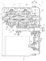
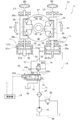
- FIG. 2 is a schematic cross-sectional view of the power generation device of FIG. 1 cut along a cut surface of a casing and is a schematic cross-sectional view schematically showing a power transmission path of the power generation device.
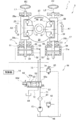
- It is a circuit diagram which shows the hydraulic circuit of the transmission provided in the electric power generating apparatus of 1st Embodiment.
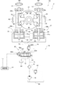
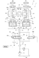
- It is a circuit diagram which shows the hydraulic circuit of the transmission provided in the electric power generating apparatus of 2nd Embodiment.
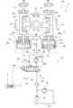
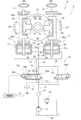
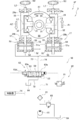
- It is a circuit diagram which shows the hydraulic circuit of the transmission provided in the electric power generating apparatus of 3rd Embodiment.
- a power generation system 2 shown in FIGS. 1 to 3 is mounted on an aircraft engine (not shown), for example, and generates electric power by rotational power from the engine.
- the power generation system 2 includes a transmission 1, a generator 3, and a power transmission mechanism 12 that transmits a rotational driving force output from the transmission 1 to the generator 3.
- the transmission 1 has a function of shifting the rotational driving force of the engine and transmitting it to the generator 3, and is configured to change the gear ratio steplessly.
- the transmission 1 includes a toroidal continuously variable transmission 11 (hereinafter also referred to as “transmission 11”), a hydraulic drive mechanism 13, and a controller 14.
- the generator 3, the transmission 11, and the hydraulic drive mechanism 13 are accommodated in the casing 4 and constitute a drive mechanism integrated power generator 5 (hereinafter also referred to as “power generator”).
- the controller 14 is disposed outside the casing 4.
- the power generation device 5 has a device input shaft 21 exposed from the casing 4, and the rotational power transmitted from the engine to the device input shaft 21 is transmitted to the transmission 11 via the transmission gear 22.
- the transmission 11 is a traction drive type continuously variable transmission.
- the transmission 11 is a double cavity half-toroidal continuously variable transmission.
- the transmission 11 includes a transmission input gear 23, a transmission input shaft 24, an input disk 25, a transmission output shaft 26, an output disk 27, a power roller 28, and a trunnion 29.
- the device input shaft 21 is housed in the casing 4 so as to be rotatable about its axis, and one end portion thereof protrudes outward from the casing 4.
- One end of the device input shaft 21 is connected to the engine, and the device input shaft 21 is rotated by receiving rotational driving force from the engine.
- a transmission gear 22 is provided at the other end of the device input shaft 21, and the transmission gear 22 rotates integrally with the device input shaft 21.
- the transmission gear 22 meshes with a transmission input gear 23, and the transmission input gear 23 is formed integrally with an intermediate portion in the axial direction of the transmission input shaft 24.
- the transmission input shaft 24 is provided in the casing 4 so as to be rotatable around the axis L ⁇ b> 1, and is rotated by the rotational driving force of the device input shaft 21 transmitted through the transmission gear 22 and the transmission input gear 23. It has become.
- An input disk 25 is provided at each end of the transmission input shaft 24 so as to rotate integrally by spline coupling or the like.
- the transmission input shaft 24 is formed in a hollow cylindrical shape, and the transmission output shaft 26 is inserted through the inner hole thereof.
- the transmission output shaft 26 is provided in the casing 4 so as to be rotatable around the axis L ⁇ b> 1, and is rotated independently of the transmission input shaft 24.
- output disks 27 are provided so as to correspond to the input disks 25, and are disposed so as to face the corresponding input disks 25. Further, the output disk 27 rotates integrally with the transmission output shaft 26 by spline coupling or the like, and a cavity 30 is formed between the output disk 27 and the corresponding input disk 25.
- the cavity 30 is formed around the entire circumference of the transmission output shaft 26 in the circumferential direction, and the circumferential cross section of the cavity 30 has a semicircular shape.
- a pair of power rollers 28 are arranged in the cavity 30 having such a shape. In FIG. 1 and FIG. 2, for convenience of explanation, the pair of power rollers 28 and 28 are shown in different positions.
- the pair of power rollers 28 are preferably arranged as shown in FIG.
- the positions of the pair of power rollers 28 are not limited to the positions shown in FIG. 1 and may be arranged as shown in FIG. The same applies to the positions of the trunnion 29 and the roller shaft 31.
- the pair of power rollers 28, 28 are arranged at equal intervals in the circumferential direction in the cavity 30, that is, shifted by 180 degrees.
- the power roller 28 is a substantially annular plate member, and its outer peripheral surface is partially spherical.
- the surfaces of the input disk 25 and the output disk 27 facing each other have a semicircular cross section in accordance with the shape of the outer peripheral surface of the power roller 28, and each power roller 28 has the input disk 25 and the output disk 27. It fits in between and is clamped from both sides in the axial direction.
- the power roller 28 has a roller shaft 31 inserted through an inner hole 28 a thereof, and is configured to be rotatable about the roller shaft 31.
- the roller shaft 31 is formed integrally with a thrust bearing 32, and the power roller 28 is rotatably provided on and supported by the trunnion 29 via the thrust bearing 32.
- the trunnion 29 is generally U-shaped as shown in FIGS. 1 and 3, and the power roller 28 is disposed between the side wall portions 29a and 29b of the trunnion 29, and the thrust bearing 32 is mounted on the main body portion 29c. It is provided intervening.
- the trunnion 29 has shaft members 33 and 33 on the side wall portions 29a and 29b, respectively.
- the shaft members 33 and 33 are pivotally supported so as to be rotatable. Accordingly, the trunnion 29 can be rotated around the central axis (that is, the rotation axis L2) of the shaft members 33, 33, and the power roller 28 is tilted by the rotation, so that the power roller 28 is tilted.
- the tilt angle of the power roller 28 is an angle formed by the roller shaft 31 with respect to a line orthogonal to the axis of the transmission output shaft 26 in a plan view in the direction along the rotation axis L2.
- the power roller 28 and each of the disks 25 and 27 are in contact with each other via a high-viscosity lubricating oil film.
- 27 and the power roller 28 generate fluid friction.
- the power roller 28 is rotated by the rotational driving force of the input disk 25, and the power roller 28 further rotates the output disk 27. That is, the rotational driving force of the input disk 25 is transmitted to the output disk 27 via the power roller 28 and the lubricating oil film.
- the rotational drive transmitted from the input disk 25 to the output disk 27 is changed by changing the contact position between the power roller 28 and each of the disks 25, 27. In this embodiment, the tilt angle of the power roller 28 is changed.
- the gear ratio of the force changes. That is, in the transmission 11, the rotational driving force input to the input disk 25 is shifted at a gear ratio corresponding to the tilt angle of the power roller 28 and transmitted to the output disk 27.
- the output disk 27 to which the rotational driving force is transmitted in this way is attached to each end of the transmission output shaft 26, and the power transmission mechanism 12 is provided on one of the two output disks 27. ing.
- the power transmission mechanism 12 is configured to transmit the rotational driving force transmitted to the output disk 27 to the generator 3 and the hydraulic pumps 15 and 16 that are auxiliary devices.
- the power transmission mechanism 12 has a plurality of gears 41 to 47.
- the first gear 41 is connected to one output disk 27 by spline coupling or the like, and rotates integrally with the one output disk 27.
- the first gear 41 meshes with the second gear 42, and the second gear 42 meshes with the third gear 43.
- the fourth gear 44 is engaged with the third gear 43, and the fourth gear 44 is attached to the generator input shaft 3 a of the generator 3.
- the second gear 42 is provided with a fifth gear 45 that rotates integrally therewith. As shown in FIG.
- a sixth gear 46 and a seventh gear 47 are engaged with the fifth gear 45, and the sixth gear 46 and the seventh gear 47 are attached to the input shafts of the hydraulic pumps 15 and 16. ing.
- the rotational driving force transmitted to the output disk 27 is input to each of the generator 3 and the hydraulic pumps 15 and 16 via the first to seventh gears 41 to 47.
- the generator 3 generates electric power with the input rotational driving force, and the hydraulic pumps 15 and 16 are rotationally driven with the input rotational driving force to discharge pressure oil.
- the transmission 1 configured as described above further includes a trunnion drive mechanism 17 and a hydraulic pressure supply device 18 shown in FIG.
- the trunnion drive mechanism 17 is provided in association with each trunnion 29, and reciprocates the corresponding trunnion 29 in the deceleration direction and the acceleration direction along the rotation axis L2.
- the trunnion drive mechanism 17 having such a function includes a piston 51 and a cylinder 52, and constitutes a cylinder mechanism.
- the piston 51 is formed integrally with the shaft member 33 of the trunnion 29 and is inserted through the cylinder 52.
- a pressure receiving portion 51 a is formed on the outer peripheral surface of the intermediate portion of the piston 51 so as to extend over the entire circumference in the circumferential direction and protrude outward in the radial direction.
- the cylinder 52 is partitioned from the deceleration chamber 53 and the acceleration chamber 54 by the pressure receiving portion 51a.
- the trunnion drive mechanism 17 is provided in association with each trunnion 29, and two trunnion drive mechanisms 17 are provided for the pair of disks 25 and 27.
- Each of the two trunnion drive mechanisms 17 is configured to displace the two trunnions 29 in directions opposite to each other. For example, when one trunnion drive mechanism 17 moves the piston 51 forward (see arrow A1 in FIG. 3), the other trunnion drive mechanism 17 moves the piston 51 backward (see arrow A2 in FIG. 3). Yes. Therefore, in the two trunnion drive mechanisms 17, the positions of the deceleration chamber 53 and the acceleration chamber 54 in the cylinder 52 are reversed.
- the deceleration chamber 53 of one trunnion drive mechanism 17 is positioned closer to the trunnion 29 than the pressure receiving portion 51a, and the acceleration chamber 54 of the other trunnion drive mechanism 17 is positioned closer to the trunnion 29 than the pressure receiving portion 51a. It has become.
- the direction in which the piston 51 moves forward is the deceleration direction
- the direction in which the piston 51 moves backward is the deceleration direction.
- the reverse direction is the speed increasing direction.
- each trunnion drive mechanism 17 moves the piston 51 in the deceleration direction or the acceleration direction so that the trunnion 29 moves in the deceleration direction or the acceleration direction.
- the trunnion drive mechanism 17 is a hydraulic cylinder mechanism.
- pressure oil is supplied to the deceleration chamber 53, the trunnion 29 moves in the deceleration direction and the power roller 28 tilts, so that the gear ratio increases and the speed increases.
- pressure oil is supplied to the chamber 54, the trunnion 29 moves in the speed increasing direction, the power roller is tilted, and the gear ratio is reduced.
- the trunnion drive mechanism 17 is supplied with pressure oil by a hydraulic pressure supply device 18.
- the hydraulic pressure supply device 18 mainly includes the hydraulic pump 15 described above, a filter 61, a relief valve 62, a direction switching valve 63, a tank 64, and a discharge valve 65.
- the hydraulic pump 15 is driven by the rotational driving force input via the transmission 11 and the power transmission mechanism 12, and discharges the pressure oil.
- the hydraulic pump 15 is connected to the main passage 71 so that the discharged pressure oil flows through the main passage 71.
- a filter 61 is interposed in the main passage 71 to remove foreign substances contained in the pressure oil.
- a relief valve 62 is provided in the main passage 71 so as to branch upstream of the filter 61.
- the relief valve 62 is configured to relieve pressure oil in the tank 64 when the pressure in the main passage 71 exceeds a predetermined relief pressure.
- a direction switching valve 63 is connected to the downstream side of the filter 61 in the main passage 71.
- the direction switching valve 63 is an electrohydraulic servo valve (for example, a flapper nozzle type valve) having a spool 63a, and has four ports. The position of the spool 63a can be changed, and the connection state of the four ports is switched according to the position of the spool 63a.
- a main passage 71, a tank passage 72, a deceleration side passage 73, and a speed increasing side passage 74 are connected to each of the four ports.
- the tank passage 72 is connected to the tank 64
- the deceleration side passage 73 is connected to the deceleration chamber 53 of each trunnion drive mechanism 17
- the speed increase side passage 74 is connected to the speed increase chamber 54 of each trunnion drive mechanism 17.
- the spool 63a is provided with an electromagnetic pilot mechanism 63d for adjusting its position.
- the electromagnetic pilot mechanism 63d includes, for example, an electromagnetic pilot valve.
- the electromagnetic pilot mechanism 63d applies a pilot pressure to the spool 63a according to the shift signal input to the electromagnetic pilot valve, and the spool 63a moves to a position corresponding to the pilot pressure. .
- the spool 63a is moved to three positions, specifically, first to third positions S1 to S3 according to the pilot pressure to be received.
- the main passage 71 is connected to the deceleration side passage 73 and the tank passage 72 is connected to the acceleration side passage 74 by the spool 63a.
- all four ports are blocked, that is, all four passages 71-74 are blocked.
- the main passage 71 is connected to the acceleration side passage 74 and the tank passage 72 is connected to the deceleration side passage 73.
- the spool 63a is positioned at the first position S1 in a state where no shift signal is input to the electromagnetic pilot mechanism 63d (for example, the power of the electromagnetic pilot mechanism 63d is off).
- the signal is input to the electromagnetic pilot mechanism 63d and the pilot pressure increases
- the spool 63a moves toward the second position S2 while reducing the opening area of each port, and reaches the second position.
- Each port is blocked.
- the connection state is switched so that the main passage 71 is connected to the speed increasing side passage 74 and the tank passage 72 is connected to the speed reducing side passage 73, and each port is opened. It moves toward the third position S3 while increasing the area.
- the direction switching valve 63 changes the direction in which the pressure oil flows in accordance with a shift signal input thereto, and either one of the deceleration chamber 53 and the acceleration chamber 54 is changed.
- the piston 51 of each trunnion drive mechanism 17 advances and retreats, and the trunnion 29 moves in the deceleration direction or the acceleration direction.
- the power roller 28 tilts and the gear ratio changes.
- the direction switching valve 63 serving as a servo valve shuts off the four passages 71 to 74 by a sleeve 63e provided therein, and Maintain position. As a result, the transmission ratio of the transmission 11 is maintained at a shift according to the shift signal.
- the main passage 71 is blocked by the direction switching valve 63, so that the hydraulic pressure increases.
- the relief valve 62 opens and the pressure oil in the main passage 71 is discharged to the tank 64 side. Further, a discharge valve 65 for discharging the pressure oil to the tank 64 is connected to the speed increasing side passage 74.
- the discharge valve 65 is a so-called normally open type electromagnetic opening / closing valve that opens and closes between the speed increasing side passage 74 and the tank 64. More specifically, the discharge valve 65 can receive a shut-off signal. When the shut-off signal is input, the exhaust valve 65 is shut off between the speed increasing side passage 74 and the tank 64 and closed. . On the other hand, when the input of the shut-off signal stops, the discharge valve 65 connects the speed increasing side passage 74 to the tank 64, discharges the pressure oil from the speed increasing chamber 54 of each trunnion drive mechanism 17, and guides it to the tank 64. ing.
- the discharge valve 65 discharges the pressure oil from the speed increasing chamber 54 regardless of the position of the direction switching valve 63.
- the discharge valve 65 operating in this manner discharges the pressure oil from the speed increasing chamber 54 and also stops the supply of the pressure oil from the hydraulic pump 15 to the speed increasing chamber 54, so that the piston 51 of each trunnion drive mechanism 17 decelerates. Advances and retracts to the chamber 53 side. As a result, the trunnion 29 can be moved in the deceleration direction to reach the maximum deceleration position, and as a result, the power roller 28 tilts to the maximum deceleration angle. By doing so, the gear ratio of the transmission 11 is increased to the maximum reduction ratio, and the rotational driving force input to the input disk 25 is sufficiently decelerated at the maximum reduction ratio and input to the generator 3. Thus, by setting the transmission ratio of the transmission 11 to the maximum reduction ratio, it is possible to prevent the rotational speed of the generator 3 from exceeding the allowable rotational speed.
- the discharge valve 65 that performs such an operation is electrically connected to the controller 14.
- the controller 14 is also electrically connected to the direction switching valve 63, and outputs a shift signal and a cutoff signal to control the movement of the valves 63 and 65.
- a rotation speed sensor 19 is connected to the controller 14.
- the rotational speed sensor 19 outputs a signal corresponding to the rotational speed on the output side shifted by the transmission 11, and is arranged in the power transmission path from the transmission output shaft 26 to the generator 3. .
- the rotation speed sensor 19 is provided in the third gear 43, and the controller 14 determines the rotation speed on the output side of the transmission 11 based on a signal output from the rotation speed sensor 19. It comes to detect.
- the target rotational speed is set or inputted in advance, and the direction switching valve 63 is set so that the rotational speed detected based on the signal of the rotational speed sensor 19 becomes the target rotational speed. It is designed to control the movement of. Further, the controller 14 is input or preset with an allowable rotational speed larger than the target rotational speed, and based on the rotational speed detected based on the signal of the rotational speed sensor 19 and the allowable rotational speed. It is determined whether or not a predetermined discharge condition is satisfied.
- the predetermined discharge condition is, for example, that the detected rotational speed exceeds the allowable rotational speed.
- the controller 14 controls the movement of the discharge valve 65 based on whether or not a predetermined discharge condition is satisfied.
- a rotational driving force of an engine (not shown) is input to the device input shaft 21 of the transmission 1, and the rotational driving force is further generated via the transmission 11 and the power transmission mechanism 12.
- the generator 3 is configured to generate electric power when a rotational driving force having a predetermined rotational speed is input.
- the rotational driving force having a target rotational speed corresponding to the predetermined rotational speed is generated by the generator 3.
- the gear ratio of the transmission 11 is adjusted so that the output of the transmission 11 is output. More specifically, the controller 14 detects the rotational speed based on a signal from the rotational speed sensor 19 and calculates a deviation between the detected rotational speed and the target rotational speed.
- the controller 14 outputs a speed change signal corresponding to the deviation to the direction switching valve 63 to adjust the speed ratio by changing the position of the spool 63a, and adjust the speed ratio so that the detected speed becomes the target speed. adjust.
- the rotational speed of the rotational driving force input to the generator 3 is adjusted to a specified rotational speed, and electricity is generated from the generator 3.
- the rotational speed of the rotational driving force input to the generator 3 may not be adjusted to the target rotational speed due to various situations.
- the spool 63a of the direction switching valve 63 is stuck and does not move, and when the spool 63a is stuck to the third position S3 from the second position S2, the trunnion 29 is increased in the speed increasing direction. Moving. Then, the rotational driving force input to the device input shaft 21 is increased by the transmission 11 and input to the generator 3. If the rotational driving force continues to be increased, the rotational speed on the output side increases, and the rotational speed detected eventually exceeds the allowable rotational speed.
- the controller 14 determines that the discharge condition is satisfied, and stops the cutoff signal output to the discharge valve 65. Then, the pressure oil is discharged from the speed increasing chamber 54 of each trunnion drive mechanism 17, and the speed ratio of the transmission 11 increases to the maximum speed reduction ratio. Thereby, it can prevent that the rotation speed of the generator 3 becomes large too much, and can prevent that the generator 3 rotates with an undesired rotation speed.
- the power generation system 2 can reduce the rotational speed of the generator 3 without stopping the rotational driving force input to the device input shaft 21. That is, the rotational speed of the generator 3 can be reduced without stopping the engine. Therefore, it is particularly preferably used for a vehicle such as an aircraft in which the engine cannot be stopped.
- the transmission 1A of the second embodiment is similar in configuration to the transmission 1 of the first embodiment.
- the configuration of the transmission 1A of the second embodiment will be mainly described with respect to differences from the configuration of the transmission 1 of the first embodiment, and the same components will be denoted by the same reference numerals and description thereof will be omitted.
- the hydraulic pressure supply device 18 has a discharge valve 65A.
- the discharge valve 65 ⁇ / b> A is a so-called normally open electromagnetic open / close valve, and is connected to the deceleration side passage 73 and the acceleration side passage 74 to open and close between the deceleration side passage 73 and the acceleration side passage 74. ing.
- the discharge valve 65A closes by closing the space between the deceleration side passage 73 and the acceleration side passage 74, and when the input of the cutoff signal stops, the discharge valve 65A It is designed to communicate between them.
- the controller 14 when it is determined that the discharge condition is not satisfied, the controller 14 outputs a cutoff signal to the discharge valve 65A. On the other hand, if it determines with satisfy
- a continuously variable transmission such as the transmission 11
- a load load from the hydraulic pumps 15 and 16
- the load moves the trunnion 29 to the deceleration side. It acts on the power roller 28 in the direction to be moved.
- the discharge valve 65A communicates the deceleration side passage 73 and the acceleration side passage 74 to discharge the pressure oil from the acceleration chamber 54 and guide it to the deceleration chamber 53.
- the speed change ratio of the transmission 11 can be increased to the maximum reduction ratio more quickly than the transmission 1 of the first embodiment, and the rotational speed of the generator 3 is prevented from becoming excessively large, and an undesirable speed.
- the generator 3 can be prevented from rotating.
- the transmission 1A of the second embodiment has the same effects as the transmission 1 of the first embodiment.
- the transmission 1B of the third embodiment is similar in configuration to the transmission 1A of the second embodiment.
- a compression coil spring 55 that is an elastic member is accommodated in the deceleration chamber 53 of each trunnion drive mechanism 17.
- the compression coil spring 55 urges the pressure receiving portion 51a of the piston 51 toward the speed increasing chamber 54 (that is, the deceleration direction). Therefore, if the shutoff signal output from the controller 14 to the discharge valve 65A is stopped and the deceleration side passage 73 and the acceleration side passage 74 are communicated, the pressure oil is more actively discharged from the acceleration chamber 54. It can be led to the deceleration chamber 53.
- the speed ratio of the transmission 11 can be increased to the maximum reduction ratio more quickly than the transmission 1A of the second embodiment, and the rotational speed of the generator 3 is prevented from becoming excessively large, and an undesired rotational speed.
- the generator 3 can be prevented from rotating.
- the transmission 1B of the third embodiment has the same effects as the transmission 1 of the second embodiment.
- the transmission 1C according to the fourth embodiment is similar in configuration to the transmission 1A according to the second embodiment.
- the pressure receiving portion 51a of the piston 51C includes a deceleration side pressure receiving surface 51b positioned on the deceleration chamber 53 side and an acceleration side pressure receiving surface 51c positioned on the speed increasing chamber 54 side. And have.
- the deceleration-side pressure receiving surface 51b receives a load that moves the piston 51 in the deceleration direction from the hydraulic pressure in the deceleration chamber 53
- the acceleration-side pressure receiving surface 51c is a load that moves the piston 51 in the acceleration direction. Is received from the hydraulic pressure in the acceleration chamber 54.
- the pressure receiving area of the deceleration side pressure receiving surface 51b is larger than the pressure receiving area of the speed increasing side pressure receiving surface 51c.
- the controller 14 stops the shut-off signal output to the discharge valve 65A and connects the deceleration side passage 73 and the acceleration side passage 74, the hydraulic pressures in the deceleration chamber 53 and the acceleration chamber 54 are substantially the same. Then, the pressure receiving portion 51a is pushed by the speed increasing chamber 54. Therefore, the pressure oil can be more positively discharged from the speed increasing chamber 54 and led to the speed reducing chamber 53. As a result, the speed ratio of the transmission 11 can be increased to the maximum reduction ratio more quickly than the transmission 1A of the second embodiment, and the rotational speed of the generator 3 is prevented from becoming excessively large, and an undesired rotational speed. Thus, the generator 3 can be prevented from rotating.
- the transmission 1C according to the fourth embodiment has the same effects as the transmission 1A according to the second embodiment.
- the transmission 1D of the fifth embodiment is similar in configuration to the transmission 1 of the first embodiment.
- the hydraulic pressure supply device 18 has an electromagnetic on-off valve 65D.
- the electromagnetic on-off valve 65D which is a supply valve and a discharge valve, has four ports, and each port is connected to the main passage 71, the tank passage 72, the deceleration side passage 73, and the acceleration side passage 74.
- the electromagnetic on-off valve 65D is connected to the controller 14 so that a supply / discharge signal can be input.
- the electromagnetic on-off valve 65D closes and shuts off all four passages 71-74.
- the pressure loss at the electromagnetic on-off valve 65D when the passages 71 to 74 are communicated is smaller than the pressure loss at the direction switching valve 63.
- the controller 14 when it is determined that the discharge condition is not satisfied, the controller 14 inputs a discharge signal to the electromagnetic on-off valve 65D. On the other hand, when the controller 14 determines that the discharge condition is satisfied, the controller 14 stops the input of the discharge signal to the electromagnetic on-off valve 65D.
- a supply bypass passage 75 is formed between the main passage 71 and the deceleration side passage 73 via the electromagnetic on-off valve 65D, and the main passage 71 and the deceleration side passage 73 communicate with each other via the supply bypass passage 75.
- a discharge bypass passage 76 is formed between the tank passage 72 and the acceleration side passage 74, and the tank passage 72 and the acceleration side passage 74 are communicated with each other by the discharge bypass passage 76. Since the pressure loss of the electromagnetic on-off valve 65D is smaller than the pressure loss of the direction switching valve 63, the passages 71 to 74 are communicated so that the pressure oil from the hydraulic pump 15 passes through the supply bypass passage 75 and the deceleration chamber 53. The pressure oil in the speed increasing chamber 54 is discharged to the tank 64 via the discharge bypass passage 76.
- the electromagnetic on-off valve 65D communicates each of the passages 71 to 74, whereby pressure oil is supplied to the deceleration chamber 53 and discharged from the speed increase chamber 54.
- the speed change ratio of the transmission 11 can be increased to the maximum reduction ratio more quickly than the transmission 1 of the first embodiment, and the rotational speed of the generator 3 is prevented from becoming excessively large, and an undesirable speed.
- the generator 3 can be prevented from rotating.
- the transmission 1D of the fifth embodiment has the same effects as the transmission 1 of the first embodiment.
- the transmission 1E according to the sixth embodiment is similar in configuration to the transmission 1D according to the fifth embodiment.
- a deceleration chamber side throttle 77 is interposed in the deceleration side passage 73, and a speed increasing chamber side throttle 78 is interposed in the acceleration side passage 74.
- the electromagnetic on-off valve 65D is connected to the deceleration side passage 73 on the rear side (ie, on the trunnion drive mechanism 17 side) of the deceleration chamber side throttle 77, and on the front side (ie, on the direction switching valve 63 side) of the acceleration chamber side throttle 78. It is connected to the speed increasing side passage 74.
- the pressure loss of the flow path through which the pressure oil guided to the deceleration chamber 53 and the acceleration chamber 54 through the direction switching valve 63 increases.
- the pressure loss of the flow path through which the pressure oil guided to the deceleration chamber 53 and the speed increasing chamber 54 through the supply bypass passage 75 and the discharge bypass passage 76 becomes smaller than that of the flow path. Therefore, the pressure loss of the electromagnetic on-off valve 65D can be designed to be smaller than that of the transmission 1E of the fifth embodiment, and the electromagnetic on-off valve 65D can be downsized. Thereby, the transmission 1E can be reduced in size.
- the transmission 1E according to the sixth embodiment has the same effects as the transmission 1D according to the fifth embodiment.
- the transmission 1F of the seventh embodiment is similar in configuration to the transmission 1 of the first embodiment.
- the hydraulic pressure supply device 18 has a pressing mechanism 80.
- the pressing mechanism 80 has an electromagnetic pilot valve 81, and the electromagnetic pilot valve 81 can input a pressing signal.
- the electromagnetic pilot valve 81 is interposed in a pilot passage 82 connected to the main passage 71 and the spool 63a, and opens and closes the pilot passage 82 depending on whether or not a pressing signal is input. More specifically, the electromagnetic pilot valve 81 closes the pilot passage 82 when a pressing signal is input, and opens the pilot passage 82 when the pressing signal is stopped.
- a pilot pressure against the force of the electromagnetic pilot mechanism 63d (that is, a pilot pressure that pushes the spool 63a to move to the first position S1) is applied to the spool 63a.
- the controller 14 inputs a pressing signal to the electromagnetic pilot valve 81 when it is determined that the discharge condition is not satisfied. On the other hand, if it is determined that the discharge condition is satisfied, the controller 14 stops the pressing signal input to the electromagnetic pilot valve 81. As a result, the pilot oil acts on the spool 63a via the electromagnetic pilot valve 81.
- the pilot pressure uses the hydraulic pump 15 as a pressure source, and a large pressure can be secured. Thus, by applying a large pilot pressure to the spool 63a, the spool 63a that has stopped moving due to sticking or the like can be forcibly moved to the first position S1.
- the pressure oil in the hydraulic pump 15 is guided to the deceleration chamber 53 and the pressure oil in the acceleration chamber 54 is discharged to the tank 64.
- the transmission ratio of the transmission 11 reaches the maximum reduction ratio. Thereby, it can prevent that the rotation speed of the generator 3 becomes large too much, and can prevent that the generator 3 rotates with an undesired rotation speed.
- the transmission 1F of the seventh embodiment has the same effects as the transmission 1 of the first embodiment.
- a normally open solenoid valve is employed as the discharge valve 65, but a normally closed solenoid valve may be employed.
- the predetermined discharge condition in the controller 14 is that the detected rotation speed exceeds the allowable rotation speed, but is not necessarily limited to such discharge condition.
- the transmission ratio of the transmission 11 may exceed a predetermined upper limit transmission ratio, and the discharge condition may indicate that the output side rotational speed is excessively increased.
- a sensor for detecting the position of the spool 63a is provided, and it is discharged that the position of the spool 63a does not change despite the operation command (shift signal) being input from the controller 14 to the direction switching valve 63.
- the discharge condition may be that the angular acceleration of the transmission output shaft 26 is equal to or greater than a predetermined angular acceleration. Thereby, when the transmission output shaft 26 is accelerated rapidly, the pressure oil is discharged from the speed increasing chamber 54 before the rotational speed of the transmission output shaft 26 reaches an upper limit value (for example, allowable rotational speed). It is possible to prevent the generator 3 from rotating excessively and to prevent the generator 3 from rotating at an undesired number of rotations. Further, the discharge condition may include both the rotational speed and angular acceleration of the transmission output shaft 26, and the rotational speed and angular acceleration of the transmission output shaft 26 are the allowable rotational speed and a predetermined angular acceleration, respectively. If it becomes above, it may be determined that the discharge condition is satisfied.
- the electromagnetic on-off valve 65D is integrally configured to have the functions of a supply valve and a discharge valve, but may be provided separately. That is, each valve may be provided such that a supply valve is interposed in the supply bypass passage 75 and a discharge valve is interposed in the discharge bypass passage 76. Further, in the transmission 1E of the sixth embodiment, the throttles 77 and 78 are interposed before branching in the passages 73 and 74, but 73 and 74 may be interposed in the passages after branching. Even in this case, the same effects can be obtained.
- the hydraulic pump 15 is used as the pressure source of the electromagnetic pilot valve 81, but a pilot pump (not shown) may be used as the pressure source.
- the electromagnetic pilot valve 81 is configured to open the pilot passage 82 when a pressing signal is input, but may be configured to close the pilot passage 82 when a pressing signal is input.
- the electromagnetic pilot valve 81 is used as the pressing mechanism 80, the electromagnetic pilot valve 81 is not necessarily required.
- a ball screw mechanism may be employed as the pressing mechanism 80. The ball screw mechanism is configured to drive the ball screw by a motor.
- the present invention is not limited to the above-described embodiment, and the configuration can be changed, added, or deleted without departing from the spirit of the present invention.
- the above embodiments may be arbitrarily combined with each other. For example, some configurations or methods in one embodiment may be applied to other embodiments.
- the transmission shown in the above-described embodiment is not limited to the application to a power generation device such as an aircraft, but may be used for a power generation device for other purposes, or for an application to an automobile or various industrial machines.
Landscapes
- Engineering & Computer Science (AREA)
- General Engineering & Computer Science (AREA)
- Mechanical Engineering (AREA)
- Power Engineering (AREA)
- Chemical & Material Sciences (AREA)
- Combustion & Propulsion (AREA)
- Transportation (AREA)
- Friction Gearing (AREA)
- Control Of Transmission Device (AREA)
- Connection Of Motors, Electrical Generators, Mechanical Devices, And The Like (AREA)
Priority Applications (2)
| Application Number | Priority Date | Filing Date | Title |
|---|---|---|---|
| US15/557,635 US10724613B2 (en) | 2015-03-13 | 2016-03-08 | Transmission device and power generation system including transmission device |
| EP16764439.2A EP3270010B1 (en) | 2015-03-13 | 2016-03-08 | Transmission and power generation system provided with same |
Applications Claiming Priority (2)
| Application Number | Priority Date | Filing Date | Title |
|---|---|---|---|
| JP2015050911A JP6505477B2 (ja) | 2015-03-13 | 2015-03-13 | 変速装置及びそれを備える発電システム |
| JP2015-050911 | 2015-03-13 |
Publications (1)
| Publication Number | Publication Date |
|---|---|
| WO2016147606A1 true WO2016147606A1 (ja) | 2016-09-22 |
Family
ID=56918561
Family Applications (1)
| Application Number | Title | Priority Date | Filing Date |
|---|---|---|---|
| PCT/JP2016/001260 Ceased WO2016147606A1 (ja) | 2015-03-13 | 2016-03-08 | 変速装置及びそれを備える発電システム |
Country Status (4)
| Country | Link |
|---|---|
| US (1) | US10724613B2 (enExample) |
| EP (1) | EP3270010B1 (enExample) |
| JP (1) | JP6505477B2 (enExample) |
| WO (1) | WO2016147606A1 (enExample) |
Cited By (1)
| Publication number | Priority date | Publication date | Assignee | Title |
|---|---|---|---|---|
| US10655387B2 (en) * | 2014-10-20 | 2020-05-19 | Somfy Sas | Range of motorized-drive devices for screening blinds |
Families Citing this family (2)
| Publication number | Priority date | Publication date | Assignee | Title |
|---|---|---|---|---|
| JP6709021B2 (ja) * | 2015-03-09 | 2020-06-10 | 川崎重工業株式会社 | トロイダル無段変速機および駆動機構一体型発電装置 |
| JP7492896B2 (ja) * | 2020-10-12 | 2024-05-30 | カワサキモータース株式会社 | ギヤ変速機付き車両の制御装置及び制御方法 |
Citations (3)
| Publication number | Priority date | Publication date | Assignee | Title |
|---|---|---|---|---|
| JP2006194391A (ja) * | 2005-01-17 | 2006-07-27 | Toyota Motor Corp | 油流制御弁の対向接続による油圧制御装置 |
| JP2008261501A (ja) * | 2008-04-21 | 2008-10-30 | Toyota Motor Corp | 油流制御弁の対向接続による油圧制御装置 |
| JP2010025270A (ja) * | 2008-07-22 | 2010-02-04 | Toyota Motor Corp | トロイダル式無段変速機の油圧制御装置 |
Family Cites Families (17)
| Publication number | Priority date | Publication date | Assignee | Title |
|---|---|---|---|---|
| JPH08233083A (ja) | 1995-02-27 | 1996-09-10 | Isuzu Motors Ltd | トロイダル型無段変速機の変速制御装置 |
| JPH10274301A (ja) * | 1997-03-31 | 1998-10-13 | Isuzu Motors Ltd | トロイダル型無段変速機 |
| WO1998044279A1 (en) * | 1997-03-31 | 1998-10-08 | Isuzu Motors Limited | Toroidal continuously variable transmission |
| DE19757015A1 (de) * | 1997-12-20 | 1999-06-24 | Zahnradfabrik Friedrichshafen | Kraftfahrzeuggetriebe mit einer automatisch stufenlos verstellbaren Übersetzung |
| JP4151500B2 (ja) * | 2003-07-18 | 2008-09-17 | トヨタ自動車株式会社 | 油流制御弁の対向接続による油圧制御装置 |
| JP4173795B2 (ja) * | 2003-11-14 | 2008-10-29 | 株式会社豊田中央研究所 | トロイダル式cvtの変速制御装置 |
| JP4781336B2 (ja) * | 2007-09-10 | 2011-09-28 | トヨタ自動車株式会社 | 油圧制御装置 |
| CN102084158B (zh) * | 2008-12-15 | 2013-06-05 | 丰田自动车株式会社 | 无级变速器 |
| US8401752B2 (en) * | 2009-12-16 | 2013-03-19 | Allison Transmission, Inc. | Fail-to-neutral system and method for a toroidal traction drive automatic transmission |
| US8578802B2 (en) * | 2009-12-16 | 2013-11-12 | Allison Transmission, Inc. | System and method for multiplexing gear engagement control and providing fault protection in a toroidal traction drive automatic transmission |
| CA2821956C (en) * | 2010-12-15 | 2018-09-11 | Allison Transmission, Inc. | Variator multiplex valve scheme for a toroidal traction drive transmission |
| EP2655938A4 (en) * | 2010-12-15 | 2016-07-27 | Allison Transm Inc | DRIVE SWITCHING VALVE PROGRAM FOR TORONTO TRACTION DRIVE TRANSMISSION |
| US20130035200A1 (en) * | 2011-02-03 | 2013-02-07 | Nsk Ltd | Toroidal continuously variable transmission |
| WO2012137844A1 (ja) * | 2011-04-07 | 2012-10-11 | 川崎重工業株式会社 | 航空機用エンジン |
| JP5755689B2 (ja) * | 2013-06-26 | 2015-07-29 | 川崎重工業株式会社 | トロイダル型無段変速機 |
| JP5632049B1 (ja) * | 2013-07-10 | 2014-11-26 | 川崎重工業株式会社 | 無段変速機の制御用油圧回路 |
| JP2015017664A (ja) * | 2013-07-11 | 2015-01-29 | 日本精工株式会社 | 電気自動車用駆動装置 |
-
2015
- 2015-03-13 JP JP2015050911A patent/JP6505477B2/ja active Active
-
2016
- 2016-03-08 WO PCT/JP2016/001260 patent/WO2016147606A1/ja not_active Ceased
- 2016-03-08 US US15/557,635 patent/US10724613B2/en active Active
- 2016-03-08 EP EP16764439.2A patent/EP3270010B1/en active Active
Patent Citations (3)
| Publication number | Priority date | Publication date | Assignee | Title |
|---|---|---|---|---|
| JP2006194391A (ja) * | 2005-01-17 | 2006-07-27 | Toyota Motor Corp | 油流制御弁の対向接続による油圧制御装置 |
| JP2008261501A (ja) * | 2008-04-21 | 2008-10-30 | Toyota Motor Corp | 油流制御弁の対向接続による油圧制御装置 |
| JP2010025270A (ja) * | 2008-07-22 | 2010-02-04 | Toyota Motor Corp | トロイダル式無段変速機の油圧制御装置 |
Non-Patent Citations (1)
| Title |
|---|
| See also references of EP3270010A4 * |
Cited By (1)
| Publication number | Priority date | Publication date | Assignee | Title |
|---|---|---|---|---|
| US10655387B2 (en) * | 2014-10-20 | 2020-05-19 | Somfy Sas | Range of motorized-drive devices for screening blinds |
Also Published As
| Publication number | Publication date |
|---|---|
| US20180066735A1 (en) | 2018-03-08 |
| JP6505477B2 (ja) | 2019-04-24 |
| EP3270010B1 (en) | 2021-05-26 |
| US10724613B2 (en) | 2020-07-28 |
| EP3270010A1 (en) | 2018-01-17 |
| JP2016169828A (ja) | 2016-09-23 |
| EP3270010A4 (en) | 2018-11-14 |
Similar Documents
| Publication | Publication Date | Title |
|---|---|---|
| JP5170255B2 (ja) | シーブ位置決め装置 | |
| JP2005188694A (ja) | トロイダル型無段変速機 | |
| WO2016147606A1 (ja) | 変速装置及びそれを備える発電システム | |
| JP2004278780A (ja) | トロイダル型無段変速機 | |
| JP3909935B2 (ja) | ポンプ制御装置 | |
| JP2007303485A (ja) | ベルト式無段変速機の駆動装置 | |
| JP4882965B2 (ja) | トロイダル式無段変速機 | |
| JP4935343B2 (ja) | 無段変速機用の油圧制御装置 | |
| JP2005207499A (ja) | 建設機械の油圧回路 | |
| JP4628568B2 (ja) | 油圧モータによる変速装置 | |
| JP6384249B2 (ja) | トロイダル型無段変速機 | |
| JP2794695B2 (ja) | 車両用ベルト式無段変速機の制御装置 | |
| JP5054478B2 (ja) | 作業車の旋回制御装置 | |
| WO2019058711A1 (ja) | 液圧モータ制御装置 | |
| JP4383363B2 (ja) | バルブ装置 | |
| JP2000130566A (ja) | 変速機の変速制御用油圧回路 | |
| JP3302786B2 (ja) | トロイダル型無段変速機のバルブボディ構造 | |
| JP6627259B2 (ja) | トロイダル型無段変速機 | |
| JP6631067B2 (ja) | 無段変速装置 | |
| JP2016109150A (ja) | 無段変速装置 | |
| JP5385618B2 (ja) | 作業車の旋回制御装置 | |
| JP3302787B2 (ja) | トロイダル型無段変速機の変速比制御装置 | |
| JP6492627B2 (ja) | 無段変速装置 | |
| JP2000352401A (ja) | 可変容量型油圧モータの容量制御装置 | |
| JP2022129324A (ja) | 作業車輌 |
Legal Events
| Date | Code | Title | Description |
|---|---|---|---|
| 121 | Ep: the epo has been informed by wipo that ep was designated in this application |
Ref document number: 16764439 Country of ref document: EP Kind code of ref document: A1 |
|
| WWE | Wipo information: entry into national phase |
Ref document number: 15557635 Country of ref document: US |
|
| NENP | Non-entry into the national phase |
Ref country code: DE |
|
| REEP | Request for entry into the european phase |
Ref document number: 2016764439 Country of ref document: EP |