WO2016147547A1 - 画像生成装置 - Google Patents
画像生成装置 Download PDFInfo
- Publication number
- WO2016147547A1 WO2016147547A1 PCT/JP2016/000720 JP2016000720W WO2016147547A1 WO 2016147547 A1 WO2016147547 A1 WO 2016147547A1 JP 2016000720 W JP2016000720 W JP 2016000720W WO 2016147547 A1 WO2016147547 A1 WO 2016147547A1
- Authority
- WO
- WIPO (PCT)
- Prior art keywords
- image
- notification target
- vehicle
- ripple
- image generation
- Prior art date
- Legal status (The legal status is an assumption and is not a legal conclusion. Google has not performed a legal analysis and makes no representation as to the accuracy of the status listed.)
- Ceased
Links
Images


Classifications
-
- G—PHYSICS
- G08—SIGNALLING
- G08G—TRAFFIC CONTROL SYSTEMS
- G08G1/00—Traffic control systems for road vehicles
- G08G1/16—Anti-collision systems
- G08G1/166—Anti-collision systems for active traffic, e.g. moving vehicles, pedestrians, bikes
-
- B—PERFORMING OPERATIONS; TRANSPORTING
- B60—VEHICLES IN GENERAL
- B60K—ARRANGEMENT OR MOUNTING OF PROPULSION UNITS OR OF TRANSMISSIONS IN VEHICLES; ARRANGEMENT OR MOUNTING OF PLURAL DIVERSE PRIME-MOVERS IN VEHICLES; AUXILIARY DRIVES FOR VEHICLES; INSTRUMENTATION OR DASHBOARDS FOR VEHICLES; ARRANGEMENTS IN CONNECTION WITH COOLING, AIR INTAKE, GAS EXHAUST OR FUEL SUPPLY OF PROPULSION UNITS IN VEHICLES
- B60K35/00—Instruments specially adapted for vehicles; Arrangement of instruments in or on vehicles
- B60K35/10—Input arrangements, i.e. from user to vehicle, associated with vehicle functions or specially adapted therefor
-
- B—PERFORMING OPERATIONS; TRANSPORTING
- B60—VEHICLES IN GENERAL
- B60K—ARRANGEMENT OR MOUNTING OF PROPULSION UNITS OR OF TRANSMISSIONS IN VEHICLES; ARRANGEMENT OR MOUNTING OF PLURAL DIVERSE PRIME-MOVERS IN VEHICLES; AUXILIARY DRIVES FOR VEHICLES; INSTRUMENTATION OR DASHBOARDS FOR VEHICLES; ARRANGEMENTS IN CONNECTION WITH COOLING, AIR INTAKE, GAS EXHAUST OR FUEL SUPPLY OF PROPULSION UNITS IN VEHICLES
- B60K35/00—Instruments specially adapted for vehicles; Arrangement of instruments in or on vehicles
- B60K35/20—Output arrangements, i.e. from vehicle to user, associated with vehicle functions or specially adapted therefor
- B60K35/21—Output arrangements, i.e. from vehicle to user, associated with vehicle functions or specially adapted therefor using visual output, e.g. blinking lights or matrix displays
- B60K35/213—Virtual instruments
-
- B—PERFORMING OPERATIONS; TRANSPORTING
- B60—VEHICLES IN GENERAL
- B60K—ARRANGEMENT OR MOUNTING OF PROPULSION UNITS OR OF TRANSMISSIONS IN VEHICLES; ARRANGEMENT OR MOUNTING OF PLURAL DIVERSE PRIME-MOVERS IN VEHICLES; AUXILIARY DRIVES FOR VEHICLES; INSTRUMENTATION OR DASHBOARDS FOR VEHICLES; ARRANGEMENTS IN CONNECTION WITH COOLING, AIR INTAKE, GAS EXHAUST OR FUEL SUPPLY OF PROPULSION UNITS IN VEHICLES
- B60K35/00—Instruments specially adapted for vehicles; Arrangement of instruments in or on vehicles
- B60K35/20—Output arrangements, i.e. from vehicle to user, associated with vehicle functions or specially adapted therefor
- B60K35/21—Output arrangements, i.e. from vehicle to user, associated with vehicle functions or specially adapted therefor using visual output, e.g. blinking lights or matrix displays
- B60K35/23—Head-up displays [HUD]
-
- B—PERFORMING OPERATIONS; TRANSPORTING
- B60—VEHICLES IN GENERAL
- B60K—ARRANGEMENT OR MOUNTING OF PROPULSION UNITS OR OF TRANSMISSIONS IN VEHICLES; ARRANGEMENT OR MOUNTING OF PLURAL DIVERSE PRIME-MOVERS IN VEHICLES; AUXILIARY DRIVES FOR VEHICLES; INSTRUMENTATION OR DASHBOARDS FOR VEHICLES; ARRANGEMENTS IN CONNECTION WITH COOLING, AIR INTAKE, GAS EXHAUST OR FUEL SUPPLY OF PROPULSION UNITS IN VEHICLES
- B60K35/00—Instruments specially adapted for vehicles; Arrangement of instruments in or on vehicles
- B60K35/20—Output arrangements, i.e. from vehicle to user, associated with vehicle functions or specially adapted therefor
- B60K35/28—Output arrangements, i.e. from vehicle to user, associated with vehicle functions or specially adapted therefor characterised by the type of the output information, e.g. video entertainment or vehicle dynamics information; characterised by the purpose of the output information, e.g. for attracting the attention of the driver
-
- B—PERFORMING OPERATIONS; TRANSPORTING
- B60—VEHICLES IN GENERAL
- B60K—ARRANGEMENT OR MOUNTING OF PROPULSION UNITS OR OF TRANSMISSIONS IN VEHICLES; ARRANGEMENT OR MOUNTING OF PLURAL DIVERSE PRIME-MOVERS IN VEHICLES; AUXILIARY DRIVES FOR VEHICLES; INSTRUMENTATION OR DASHBOARDS FOR VEHICLES; ARRANGEMENTS IN CONNECTION WITH COOLING, AIR INTAKE, GAS EXHAUST OR FUEL SUPPLY OF PROPULSION UNITS IN VEHICLES
- B60K35/00—Instruments specially adapted for vehicles; Arrangement of instruments in or on vehicles
- B60K35/20—Output arrangements, i.e. from vehicle to user, associated with vehicle functions or specially adapted therefor
- B60K35/29—Instruments characterised by the way in which information is handled, e.g. showing information on plural displays or prioritising information according to driving conditions
-
- B—PERFORMING OPERATIONS; TRANSPORTING
- B60—VEHICLES IN GENERAL
- B60K—ARRANGEMENT OR MOUNTING OF PROPULSION UNITS OR OF TRANSMISSIONS IN VEHICLES; ARRANGEMENT OR MOUNTING OF PLURAL DIVERSE PRIME-MOVERS IN VEHICLES; AUXILIARY DRIVES FOR VEHICLES; INSTRUMENTATION OR DASHBOARDS FOR VEHICLES; ARRANGEMENTS IN CONNECTION WITH COOLING, AIR INTAKE, GAS EXHAUST OR FUEL SUPPLY OF PROPULSION UNITS IN VEHICLES
- B60K35/00—Instruments specially adapted for vehicles; Arrangement of instruments in or on vehicles
- B60K35/60—Instruments characterised by their location or relative disposition in or on vehicles
-
- B—PERFORMING OPERATIONS; TRANSPORTING
- B60—VEHICLES IN GENERAL
- B60K—ARRANGEMENT OR MOUNTING OF PROPULSION UNITS OR OF TRANSMISSIONS IN VEHICLES; ARRANGEMENT OR MOUNTING OF PLURAL DIVERSE PRIME-MOVERS IN VEHICLES; AUXILIARY DRIVES FOR VEHICLES; INSTRUMENTATION OR DASHBOARDS FOR VEHICLES; ARRANGEMENTS IN CONNECTION WITH COOLING, AIR INTAKE, GAS EXHAUST OR FUEL SUPPLY OF PROPULSION UNITS IN VEHICLES
- B60K35/00—Instruments specially adapted for vehicles; Arrangement of instruments in or on vehicles
- B60K35/80—Arrangements for controlling instruments
- B60K35/81—Arrangements for controlling instruments for controlling displays
-
- B—PERFORMING OPERATIONS; TRANSPORTING
- B60—VEHICLES IN GENERAL
- B60Q—ARRANGEMENT OF SIGNALLING OR LIGHTING DEVICES, THE MOUNTING OR SUPPORTING THEREOF OR CIRCUITS THEREFOR, FOR VEHICLES IN GENERAL
- B60Q9/00—Arrangement or adaptation of signal devices not provided for in one of main groups B60Q1/00 - B60Q7/00, e.g. haptic signalling
- B60Q9/008—Arrangement or adaptation of signal devices not provided for in one of main groups B60Q1/00 - B60Q7/00, e.g. haptic signalling for anti-collision purposes
-
- B—PERFORMING OPERATIONS; TRANSPORTING
- B60—VEHICLES IN GENERAL
- B60W—CONJOINT CONTROL OF VEHICLE SUB-UNITS OF DIFFERENT TYPE OR DIFFERENT FUNCTION; CONTROL SYSTEMS SPECIALLY ADAPTED FOR HYBRID VEHICLES; ROAD VEHICLE DRIVE CONTROL SYSTEMS FOR PURPOSES NOT RELATED TO THE CONTROL OF A PARTICULAR SUB-UNIT
- B60W50/00—Details of control systems for road vehicle drive control not related to the control of a particular sub-unit, e.g. process diagnostic or vehicle driver interfaces
- B60W50/08—Interaction between the driver and the control system
- B60W50/14—Means for informing the driver, warning the driver or prompting a driver intervention
-
- G—PHYSICS
- G01—MEASURING; TESTING
- G01S—RADIO DIRECTION-FINDING; RADIO NAVIGATION; DETERMINING DISTANCE OR VELOCITY BY USE OF RADIO WAVES; LOCATING OR PRESENCE-DETECTING BY USE OF THE REFLECTION OR RERADIATION OF RADIO WAVES; ANALOGOUS ARRANGEMENTS USING OTHER WAVES
- G01S13/00—Systems using the reflection or reradiation of radio waves, e.g. radar systems; Analogous systems using reflection or reradiation of waves whose nature or wavelength is irrelevant or unspecified
- G01S13/86—Combinations of radar systems with non-radar systems, e.g. sonar, direction finder
- G01S13/867—Combination of radar systems with cameras
-
- G—PHYSICS
- G01—MEASURING; TESTING
- G01S—RADIO DIRECTION-FINDING; RADIO NAVIGATION; DETERMINING DISTANCE OR VELOCITY BY USE OF RADIO WAVES; LOCATING OR PRESENCE-DETECTING BY USE OF THE REFLECTION OR RERADIATION OF RADIO WAVES; ANALOGOUS ARRANGEMENTS USING OTHER WAVES
- G01S13/00—Systems using the reflection or reradiation of radio waves, e.g. radar systems; Analogous systems using reflection or reradiation of waves whose nature or wavelength is irrelevant or unspecified
- G01S13/88—Radar or analogous systems specially adapted for specific applications
- G01S13/93—Radar or analogous systems specially adapted for specific applications for anti-collision purposes
- G01S13/931—Radar or analogous systems specially adapted for specific applications for anti-collision purposes of land vehicles
-
- G—PHYSICS
- G06—COMPUTING OR CALCULATING; COUNTING
- G06F—ELECTRIC DIGITAL DATA PROCESSING
- G06F3/00—Input arrangements for transferring data to be processed into a form capable of being handled by the computer; Output arrangements for transferring data from processing unit to output unit, e.g. interface arrangements
- G06F3/01—Input arrangements or combined input and output arrangements for interaction between user and computer
- G06F3/011—Arrangements for interaction with the human body, e.g. for user immersion in virtual reality
-
- G—PHYSICS
- G06—COMPUTING OR CALCULATING; COUNTING
- G06F—ELECTRIC DIGITAL DATA PROCESSING
- G06F3/00—Input arrangements for transferring data to be processed into a form capable of being handled by the computer; Output arrangements for transferring data from processing unit to output unit, e.g. interface arrangements
- G06F3/01—Input arrangements or combined input and output arrangements for interaction between user and computer
- G06F3/03—Arrangements for converting the position or the displacement of a member into a coded form
- G06F3/0304—Detection arrangements using opto-electronic means
-
- G—PHYSICS
- G06—COMPUTING OR CALCULATING; COUNTING
- G06V—IMAGE OR VIDEO RECOGNITION OR UNDERSTANDING
- G06V20/00—Scenes; Scene-specific elements
- G06V20/20—Scenes; Scene-specific elements in augmented reality scenes
-
- G—PHYSICS
- G06—COMPUTING OR CALCULATING; COUNTING
- G06V—IMAGE OR VIDEO RECOGNITION OR UNDERSTANDING
- G06V20/00—Scenes; Scene-specific elements
- G06V20/50—Context or environment of the image
- G06V20/56—Context or environment of the image exterior to a vehicle by using sensors mounted on the vehicle
-
- G—PHYSICS
- G08—SIGNALLING
- G08G—TRAFFIC CONTROL SYSTEMS
- G08G1/00—Traffic control systems for road vehicles
- G08G1/09—Arrangements for giving variable traffic instructions
- G08G1/0962—Arrangements for giving variable traffic instructions having an indicator mounted inside the vehicle, e.g. giving voice messages
-
- B—PERFORMING OPERATIONS; TRANSPORTING
- B60—VEHICLES IN GENERAL
- B60K—ARRANGEMENT OR MOUNTING OF PROPULSION UNITS OR OF TRANSMISSIONS IN VEHICLES; ARRANGEMENT OR MOUNTING OF PLURAL DIVERSE PRIME-MOVERS IN VEHICLES; AUXILIARY DRIVES FOR VEHICLES; INSTRUMENTATION OR DASHBOARDS FOR VEHICLES; ARRANGEMENTS IN CONNECTION WITH COOLING, AIR INTAKE, GAS EXHAUST OR FUEL SUPPLY OF PROPULSION UNITS IN VEHICLES
- B60K2360/00—Indexing scheme associated with groups B60K35/00 or B60K37/00 relating to details of instruments or dashboards
- B60K2360/16—Type of output information
- B60K2360/179—Distances to obstacles or vehicles
-
- B—PERFORMING OPERATIONS; TRANSPORTING
- B60—VEHICLES IN GENERAL
- B60K—ARRANGEMENT OR MOUNTING OF PROPULSION UNITS OR OF TRANSMISSIONS IN VEHICLES; ARRANGEMENT OR MOUNTING OF PLURAL DIVERSE PRIME-MOVERS IN VEHICLES; AUXILIARY DRIVES FOR VEHICLES; INSTRUMENTATION OR DASHBOARDS FOR VEHICLES; ARRANGEMENTS IN CONNECTION WITH COOLING, AIR INTAKE, GAS EXHAUST OR FUEL SUPPLY OF PROPULSION UNITS IN VEHICLES
- B60K2360/00—Indexing scheme associated with groups B60K35/00 or B60K37/00 relating to details of instruments or dashboards
- B60K2360/18—Information management
- B60K2360/186—Displaying information according to relevancy
- B60K2360/1868—Displaying information according to relevancy according to driving situations
-
- B—PERFORMING OPERATIONS; TRANSPORTING
- B60—VEHICLES IN GENERAL
- B60K—ARRANGEMENT OR MOUNTING OF PROPULSION UNITS OR OF TRANSMISSIONS IN VEHICLES; ARRANGEMENT OR MOUNTING OF PLURAL DIVERSE PRIME-MOVERS IN VEHICLES; AUXILIARY DRIVES FOR VEHICLES; INSTRUMENTATION OR DASHBOARDS FOR VEHICLES; ARRANGEMENTS IN CONNECTION WITH COOLING, AIR INTAKE, GAS EXHAUST OR FUEL SUPPLY OF PROPULSION UNITS IN VEHICLES
- B60K2360/00—Indexing scheme associated with groups B60K35/00 or B60K37/00 relating to details of instruments or dashboards
- B60K2360/20—Optical features of instruments
- B60K2360/33—Illumination features
- B60K2360/334—Projection means
-
- G—PHYSICS
- G01—MEASURING; TESTING
- G01S—RADIO DIRECTION-FINDING; RADIO NAVIGATION; DETERMINING DISTANCE OR VELOCITY BY USE OF RADIO WAVES; LOCATING OR PRESENCE-DETECTING BY USE OF THE REFLECTION OR RERADIATION OF RADIO WAVES; ANALOGOUS ARRANGEMENTS USING OTHER WAVES
- G01S13/00—Systems using the reflection or reradiation of radio waves, e.g. radar systems; Analogous systems using reflection or reradiation of waves whose nature or wavelength is irrelevant or unspecified
- G01S13/88—Radar or analogous systems specially adapted for specific applications
- G01S13/93—Radar or analogous systems specially adapted for specific applications for anti-collision purposes
- G01S13/931—Radar or analogous systems specially adapted for specific applications for anti-collision purposes of land vehicles
- G01S2013/9323—Alternative operation using light waves
-
- G—PHYSICS
- G01—MEASURING; TESTING
- G01S—RADIO DIRECTION-FINDING; RADIO NAVIGATION; DETERMINING DISTANCE OR VELOCITY BY USE OF RADIO WAVES; LOCATING OR PRESENCE-DETECTING BY USE OF THE REFLECTION OR RERADIATION OF RADIO WAVES; ANALOGOUS ARRANGEMENTS USING OTHER WAVES
- G01S13/00—Systems using the reflection or reradiation of radio waves, e.g. radar systems; Analogous systems using reflection or reradiation of waves whose nature or wavelength is irrelevant or unspecified
- G01S13/88—Radar or analogous systems specially adapted for specific applications
- G01S13/93—Radar or analogous systems specially adapted for specific applications for anti-collision purposes
- G01S13/931—Radar or analogous systems specially adapted for specific applications for anti-collision purposes of land vehicles
- G01S2013/9324—Alternative operation using ultrasonic waves
-
- G—PHYSICS
- G01—MEASURING; TESTING
- G01S—RADIO DIRECTION-FINDING; RADIO NAVIGATION; DETERMINING DISTANCE OR VELOCITY BY USE OF RADIO WAVES; LOCATING OR PRESENCE-DETECTING BY USE OF THE REFLECTION OR RERADIATION OF RADIO WAVES; ANALOGOUS ARRANGEMENTS USING OTHER WAVES
- G01S13/00—Systems using the reflection or reradiation of radio waves, e.g. radar systems; Analogous systems using reflection or reradiation of waves whose nature or wavelength is irrelevant or unspecified
- G01S13/88—Radar or analogous systems specially adapted for specific applications
- G01S13/93—Radar or analogous systems specially adapted for specific applications for anti-collision purposes
- G01S13/931—Radar or analogous systems specially adapted for specific applications for anti-collision purposes of land vehicles
- G01S2013/9327—Sensor installation details
- G01S2013/93271—Sensor installation details in the front of the vehicles
-
- G—PHYSICS
- G02—OPTICS
- G02B—OPTICAL ELEMENTS, SYSTEMS OR APPARATUS
- G02B27/00—Optical systems or apparatus not provided for by any of the groups G02B1/00 - G02B26/00, G02B30/00
- G02B27/01—Head-up displays
- G02B27/0101—Head-up displays characterised by optical features
- G02B2027/0138—Head-up displays characterised by optical features comprising image capture systems, e.g. camera
-
- G—PHYSICS
- G02—OPTICS
- G02B—OPTICAL ELEMENTS, SYSTEMS OR APPARATUS
- G02B27/00—Optical systems or apparatus not provided for by any of the groups G02B1/00 - G02B26/00, G02B30/00
- G02B27/01—Head-up displays
- G02B27/0101—Head-up displays characterised by optical features
- G02B2027/014—Head-up displays characterised by optical features comprising information/image processing systems
-
- G—PHYSICS
- G02—OPTICS
- G02B—OPTICAL ELEMENTS, SYSTEMS OR APPARATUS
- G02B27/00—Optical systems or apparatus not provided for by any of the groups G02B1/00 - G02B26/00, G02B30/00
- G02B27/01—Head-up displays
- G02B27/0101—Head-up displays characterised by optical features
- G02B2027/0141—Head-up displays characterised by optical features characterised by the informative content of the display
Definitions
- the present disclosure relates to a technique for informing a vehicle occupant of a notification target located in a traveling direction of a vehicle by an image.
- Patent Document 1 a technique for notifying a driver of an obstacle such as a pedestrian by displaying a virtual image superimposed on the foreground of a vehicle using a head-up display device is known.
- the driver's line of sight is guided to the obstacle by performing the line-of-sight guidance display that moves the image toward the position of the obstacle.
- Patent Document 1 merely indicates the current position of a notification target such as an obstacle. That is, the future state that the notification target moves on the planned course of the vehicle cannot be implied by the display. For this reason, the driver cannot be aware of the crisis, and even if the driver's line of sight is directed to the notification target, the driver may not recognize the notification target.
- This disclosure is intended to provide a technique capable of improving the certainty of recognition of a notification target by a vehicle occupant such as a driver.
- An image generation device generates an image for notifying an occupant of a vehicle of a notification target located in the traveling direction of the vehicle, and outputs the image to a head-up display device that superimposes and displays a virtual image of the image on the foreground of the vehicle To do.
- An image generation device includes a target information acquisition unit that acquires position information and a movement direction of a notification target, and a head-up display device on a road surface on which the notification target is located when at least one position information is acquired by the target information acquisition unit. And an image generation unit that generates a ripple image that is displayed in a superimposed manner and spreads in the movement direction along the road surface from the position of the notification target.
- the ripple image in the present disclosure can indicate the future destination of the notification target by a shape that expands in the moving direction of the notification target along the road surface. Therefore, a part of the ripple image may overlap with a planned course on which the vehicle will travel in the future. The future state of excessive approach between the notification target and the vehicle may be implied to the vehicle occupant. By making the occupant aware of the crisis with the ripple image, it is possible to increase the certainty of recognition of the notification target by the occupant.
- FIG. 1 is a diagram showing a layout around a driver's seat in a vehicle.
- FIG. 2 is a block diagram showing the overall configuration of the in-vehicle network.
- FIG. 3 is a diagram showing the configuration of the HUD device and the principle of virtual image display.
- FIG. 4 is a diagram illustrating an example of a ripple image in the first embodiment.
- FIG. 5 is a diagram for explaining the concept of the ripple image shown in FIG.
- FIG. 6 is a diagram illustrating an example of a ripple image when the moving speed of the notification target changes,
- FIG. 7 is a diagram for explaining the concept of the ripple image shown in FIG. FIG.
- FIG. 8 is a diagram illustrating an example of a ripple image when the traveling speed of the vehicle changes.
- FIG. 9 is a diagram for explaining the concept of the ripple image shown in FIG.
- FIG. 10 is a diagram illustrating an example of a ripple image in the low-attraction mode.
- FIG. 11 is a diagram showing functional blocks constructed in the control circuit.
- FIG. 12 is a flowchart showing processing performed by the control circuit.
- FIG. 13 is a flowchart showing processing performed by the control circuit.
- FIG. 14 is a diagram illustrating an example of a ripple image in the second embodiment.
- FIG. 15 is a diagram for explaining the concept of the ripple image shown in FIG.
- FIG. 16 is a block diagram showing a modification of the in-vehicle network of FIG.
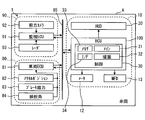
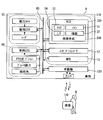
- the HCU 100 is an electronic device mounted on a vehicle A as illustrated in FIGS. 1 and 2.
- the HCU 100 is one of a plurality of nodes provided in the in-vehicle network 1.
- the in-vehicle network 1 includes an external environment recognition system 90, a vehicle control system 80, a display system 10, and a communication bus 85 to which these are connected.
- HCU stands for Human Machine Interface Control Unit, and Human Machine Interface is also called HMI.
- the vehicle A is also called the own vehicle.
- the external environment recognition system 90 includes external sensors such as a front camera unit 92 and a radar unit 93, and a surrounding monitoring ECU 91.
- the external recognition system 90 is for moving objects such as pedestrians, non-human animals, bicycles, motorcycles, and other vehicles, as well as falling objects on the road, traffic signals, guardrails, curbs, road signs, road markings, and trees. Such a stationary object is detected.
- the outside world recognition system 90 can include outside world sensors such as lidar and sonar in addition to the units 92 and 93.
- the front camera unit 92 is, for example, a monocular or compound eye camera installed near the rear mirror of the vehicle A.
- the front camera unit 92 is directed in the traveling direction CD (see FIG. 5) of the vehicle A, and can photograph a range of about 80 meters from the vehicle A with a horizontal viewing angle of about 45 degrees, for example.
- the front camera unit 92 sequentially outputs captured image data showing a moving object and a stationary object to the periphery monitoring ECU 91.
- the radar unit 93 is installed, for example, at the front part of the vehicle A (see FIG. 5).
- the radar unit 93 emits 77 GHz millimeter waves toward the traveling direction CD (see FIG. 5) of the vehicle A from the transmission antenna.
- the radar unit 93 receives millimeter waves emitted from a moving object and a stationary object in the traveling direction CD by a receiving antenna.
- the radar unit 93 can scan a range of about 60 meters from the vehicle A at a horizontal scanning angle of about 55 degrees, for example.
- the radar unit 93 sequentially outputs scanning information based on the received signal to the periphery monitoring ECU 91.
- the periphery monitoring ECU 91 is mainly configured by a microcomputer having a processor and a memory.
- the periphery monitoring ECU 91 is communicably connected to the front camera unit 92, the radar unit 93, and the communication bus 85.
- the peripheral monitoring ECU 91 detects the relative positions of moving objects and stationary objects in the traveling direction CD (see FIG. 5) by integrating the information acquired from the units 92 and 93. Specifically, the periphery monitoring ECU 91 extracts an object shown in the image data of the front camera unit 92 by image processing.
- the periphery monitoring ECU 91 calculates the relative position of the extracted moving object, stationary object, and the like (hereinafter referred to as a detection object) based on the scanning information of the radar unit 93.
- the surroundings monitoring ECU 91 calculates the moving direction MD (see FIG. 5) and moving speed Va (see FIG. 5) of the moving detection object based on the transition of the relative position.
- the periphery monitoring ECU 91 acquires the predicted collision time for the detected object based on the traveling speed Vc of the vehicle A (see FIG. 5) acquired from the communication bus 85 and the calculated relative position of the detected object.
- the collision prediction time is also called Time To Collision (TTC).
- the vehicle control system 80 includes an operation detection sensor such as an accelerator position sensor 82, a brake pedal force sensor 83, and a steering angle sensor 84, and a vehicle control ECU 81.
- the vehicle control system 80 controls the traveling of the vehicle A based on an input by a vehicle occupant (hereinafter referred to as a driver) seated in the driver's seat 17 and a detection result of the external environment recognition system 90.
- the sensors 82 to 84 are connected to the vehicle control ECU 81.
- the accelerator position sensor 82 detects the amount of depression of the accelerator pedal by the driver, and outputs it to the vehicle control ECU 81.
- the brake pedal force sensor 83 detects the pedal force of the brake pedal by the driver and outputs it to the vehicle control ECU 81.
- the steering angle sensor 84 detects the steering angle amount of the steering by the driver and outputs it to the vehicle control ECU 81.
- the vehicle control ECU 81 is mainly composed of a microcomputer having a processor and a memory.
- the vehicle control ECU 81 is connected to the communication bus 85.
- the vehicle control ECU 81 is one or a plurality of types including at least an integrated control ECU among an engine control ECU, a motor control ECU, a brake control ECU, and an integrated control ECU.
- the vehicle control ECU 81 outputs vehicle information such as the detection results of the sensors 82 to 84 and the traveling speed Vc of the vehicle A (see FIG. 5) to the communication bus 85.
- the vehicle control ECU 81 determines whether or not the emergency control condition is satisfied based on the predicted collision time acquired from the communication bus 85.
- the vehicle control ECU 81 realizes collision damage reduction braking that forcibly automatically decelerates the vehicle speed of the vehicle A when the emergency control condition is satisfied.
- the collision damage reduction braking is also called Autonomous Emergency Braking (AEB).
- AEB Autonomous Emergency Braking
- the display system 10 includes a display device such as a head-up display (HUD) device 20, a combination meter 12, and a multifunction display 13, and the HCU 100.
- the display system 10 provides information to the passengers of the vehicle A including the driver.
- the display system 10 can include an operation device that operates display of each display device.
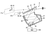
- the HUD device 20 projects light of an image based on data acquired from the HCU 100 onto the windshield 18.
- the light of the image reflected on the vehicle interior side by the windshield 18 is perceived by the driver sitting in the driver's seat 17.
- the driver can visually recognize the virtual image of the image projected by the HUD device 20 by superimposing it on an external scene in front of the vehicle A (hereinafter referred to as foreground).
- the HUD device 20 includes a laser scanner 25, a first screen 26, a second screen 27, and a concave mirror 28.
- the laser scanner 25 irradiates the screens 26 and 27 with laser light.
- the laser scanner 25 scans the laser beam based on the image data acquired from the HCU 100.
- the 1st screen 26, the 2nd screen 27, and the concave mirror 28 are formed by vapor-depositing aluminum on the surface of a resin base material or a glass base material. An image is drawn on the first screen 26 and the second screen 27 by the laser scanner 25.
- Each screen 26, 27 reflects the laser beam emitted from the laser scanner 25 toward the concave mirror 28 while diffusing it.
- the concave mirror 28 is formed in a smooth curved shape with a central portion recessed in a direction away from the screens 26 and 27. The concave mirror 28 enlarges the images on the screens 26 and 27 and projects them on the windshield 18.
- the far display area 21 and the near display area 22 onto which an image is projected by the above HUD device 20 are defined side by side on the windshield 18.
- the distant display area 21 is defined at a position substantially horizontal to the driver's eyes.
- the far display area 21 is projected with the light of the image drawn on the first screen 26.
- the light projected on the distant display area 21 is imaged on a virtual first imaging surface 21a located approximately 15 m ahead of the windshield 18.
- the near display area 22 is defined below the far display area 21.
- the light of the image drawn on the second screen 27 is projected onto the vicinity display area 22.
- the light projected on the vicinity display area 22 is imaged on a virtual second imaging surface 22a located approximately 2 m ahead of the windshield 18.
- the HCU 100 controls the display by these display devices by outputting a control signal to each display device including the HUD device 20 shown in FIG.
- the HCU 100 includes a main processor 31, a drawing processor 32, a rewritable nonvolatile memory 33, an input / output interface 34 for inputting / outputting information, and a control circuit 30 having a bus for connecting them.
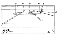
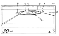
- the above display system 10 can notify the driver of a detection object such as a pedestrian detected by the external recognition system 90 as a notification target B (see FIG. 4).
- the notification of the notification target B by the display system 10 is performed by a notification image 60 displayed as a virtual image by the HUD device 20, as shown in FIGS.
- the notification image 60 includes a ripple image 61 projected on the far display area 21 and an icon 69 projected on the near display area 22. Details of the notification image 60 will be described below with reference to FIGS.
- the object to be notified B by the display system 10 is an object whose moving direction MD intersects the traveling direction CD of the vehicle A among detected objects located in the traveling direction CD of the vehicle A. It is.
- the ripple image 61 is displayed by being superimposed on the road surface on which the notification target B is located by the HUD device 20 (see FIG. 3).
- the ripple image 61 is subjected to viewpoint conversion so that the virtual mode shown in FIG. 5 is reproduced in the driver's field of view, and projected onto the distant display area 21 as shown in FIG.
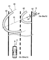
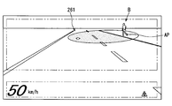
- the description relating to the ripple image 61 below mainly indicates the shape of the ripple image 61 before the viewpoint conversion. 4 and 5, the ripple image 61 is an image that spreads from the position AP of the notification target B in the movement direction MD of the notification target B along the road surface.
- the ripple image 61 has a plurality of arc-shaped image portions 62.
- the arcuate image portion 62 is curved in an elliptical arc shape so as to surround the notification target B.
- the major axis of the arcuate image portion 62 substantially coincides with the virtual line VL extending from the position AP of the notification target B along the moving direction MD of the notification target B.
- the curvature of the arcuate image portion 62 increases as it approaches the virtual line VL from both end portions 64 of the arcuate image portion 62.
- the arcuate image portion 62 can indicate the moving direction MD of the notification target B by the central top portion 63 having the maximum curvature.
- the line width LW of the arcuate image portion 62 is defined to be thicker than the line width LT of the lane marking formed on the road surface.
- the line width LW of the arcuate image portion 62 is defined to be thinner than half the lane width LaW (about 2.7 to 3.5 m) of the lane in which the vehicle A travels.
- the interval between the two arcuate image portions 62 on the virtual line VL is secured about half of the lane width LaW.
- the arcuate image unit 62 is repeatedly emitted from the position AP of the notification target B toward the movement direction MD of the notification target B.
- the arcuate image portion 62 superimposed in the vicinity of the position AP of the notification target B has a gradation that becomes lighter as the position AP is approached.
- the arcuate image portion 62 becomes unclear as it approaches the position AP of the notification target B, and becomes clear as it moves away from the notification target B.
- the arcuate image portion 62 moves toward the outer edge 65 of the ripple image 61 while maintaining a distance from another arcuate image portion 62 adjacent in the radial direction.
- the arcuate image portion 62 is enlarged in the radial direction as it moves to the outer edge 65.
- the arcuate image portion 62 is sequentially drawn from the outside by the intersection with the outer edge 65, and disappears while gradually reducing the line width LW.
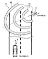
- the ripple image 61 changes the mode according to the states of the notification target B and the vehicle A. As shown in FIGS. 6 and 7, the ripple image 61 changes the position of the outer edge 65 in accordance with the moving speed Va of the notification target B.
- the outer edge 65 of the ripple image 61 is defined at a position farther from the current position AP of the notification target B as the movement speed Va of the notification target B increases. Therefore, the ripple image 61 is displayed larger as the moving speed Va of the notification target B increases.
- Such a ripple image 61 can indicate the range that the notification target B can reach when a predetermined time (for example, 3 seconds) elapses by the position of the outer edge 65.
- the cycle in which the arc-shaped image portion 62 is emitted from the position AP of the notification target B is shortened as the movement speed Va of the notification target B increases.
- the time interval from the time when the movement of one arcuate image portion 62 is started to the time when the movement of the next arcuate image portion 62 is started is shortened.
- the moving speed of the arcuate image portion 62 is increased as the moving speed Va of the notification target B increases.
- the ripple image 61 is reduced in the width direction LR orthogonal to the virtual line VL as the moving speed Va of the notification target B increases.
- each arc-shaped image portion 62 has an elliptical arc shape narrowed in the minor axis direction.
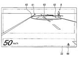
- the ripple image 61 changes the position of the outer edge 65 in accordance with the traveling speed Vc of the vehicle A as shown in FIGS.
- the predetermined time for defining the distance from the position AP of the notification target B to the outer edge 65 is lengthened as the traveling speed Vc becomes slower.
- the ripple image 61 is displayed larger as the traveling speed Vc of the vehicle A is slower.
- the number of arc-shaped image portions 62 included in the ripple image 61 can increase as the traveling speed Vc decreases.
- the display mode of the ripple image 61 is changed to a mode with a low attraction (referred to as a low attraction mode) as illustrated in FIG.
- a low attraction mode a mode with a low attraction
- Each arcuate image portion 62 in the low-attraction mode is displayed with lower brightness and less noticeable hue than the arcuate image portion 62 (see FIG. 4) in the normal mode.
- the display of the ripple image 61 is started in a state in which the notification target B is farther from the vehicle A as the traveling speed Vc of the vehicle A shown in FIG.
- the ripple image 61 is displayed on the basis that the distance D to the virtual intersection position CP is less than the threshold distance.
- the intersection position CP is a position where the traveling direction CD of the vehicle A and the movement direction MD of the notification target B intersect each other.
- the threshold distance is set to a braking distance that can stop the vehicle A with a deceleration of 0.2 G, for example.
- the display color of the ripple image 61 can be changed in order of yellow, amber, and red as the vehicle A approaches the intersection position CP.
- the ripple image 61 may be blinked when the vehicle A approaches the intersection position AP.
- the icon 69 is projected on the vicinity display area 22 as shown in FIG.
- the display of the icon 69 is started after a predetermined time (for example, about 1 second) when the display of the ripple image 61 is started.
- the icon 69 is an image for causing the driver to recognize the presence of the notification target B, similarly to the ripple image 61.
- the icon 69 is displayed in substantially the same color as the arcuate image portion 62.
- control circuit 30 shown in FIGS. 2 and 11 executes a notification program stored in the memory 33 by each of the processors 31 and 32, thereby allowing a plurality of functions.
- Build blocks 41-45 These functional blocks will be described below with reference to FIGS. 2 and 5 based on FIG.
- the image generation unit 41 is a functional block that generates image data of the ripple image 61 and the icon 69 (see FIG. 10).
- the image generation unit 41 determines the display mode of the ripple image 61 and the icon 69 based on the information acquired by the functional blocks 42 to 45.
- the image generation unit 41 generates image data of the ripple image 61 and the icon 69 in the determined mode, and outputs them to the HUD device 20.
- the target information acquisition unit 42 is a functional block that acquires the position information of the detected object including the notification target B output by the external environment recognition system 90 to the communication bus 85, the moving direction MD, and the moving speed Va.
- the own vehicle information acquisition unit 43 is a functional block that acquires information such as the traveling speed Vc of the vehicle A output to the communication bus 85 by the vehicle control system 80.
- the intersection determination unit 44 is a functional block that selects an object to be notified B from detected objects detected by the external environment recognition system 90.
- the intersection determination unit 44 determines whether the moving direction MD of the detected object intersects the traveling direction CD of the vehicle A for the detected object acquired by the target information acquiring unit 42.
- the intersection determination unit 44 sets the detected object that is determined that the moving direction MD and the traveling direction CD intersect each other as the notification target B.
- the operation determination unit 45 is a functional block that determines whether or not an operation for avoiding the notification target B is input by the driver.
- the operation determination unit 45 acquires the operation information output to the communication bus 85 by the vehicle control system 80.
- the operation determination unit 45 determines whether there is an avoidance operation that avoids the notification target B based on the acquired operation information.
- the avoidance operation includes an operation of steering the steering to the side opposite to the notification target B, an operation of loosening the accelerator, an operation of generating a deceleration by braking, and the like.
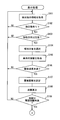
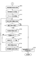
- FIGS. 12 and 13 Details of the display processing of the ripple image 61 and the icon 69 performed by the control circuit 30 will be described based on FIGS. 12 and 13 with reference to FIG.
- the processing shown in the flowcharts of FIGS. 12 and 13 is performed by the control circuit 30 (see FIG. 2) based on the fact that the vehicle A can travel by switching the selector lever 15 (see FIG. 1) to the D range. Repeatedly.
- S101 a process of acquiring detected object information such as the relative position, the moving direction MD, and the moving speed Va from the communication bus 85 (see FIG. 2) is performed, and the process proceeds to S102.
- S102 the presence or absence of the detected object is determined based on whether or not the information of the detected object has been acquired in S101. If it is determined in S102 that there is no detected object, the process returns to S101. On the other hand, if it is determined in S102 that there is a detected object, the process proceeds to S102.
- S103 it is determined whether or not the moving direction MD of the detected object intersects the traveling direction CD of the vehicle A.
- the intersection of the moving direction MD and the traveling direction CD is determined for each detected object. If it is determined in S103 that the moving direction MD of the detected object does not intersect the traveling direction CD, the process returns to S101. On the other hand, if it is determined in S103 that there is a detected object whose movement direction MD intersects the traveling direction CD, the process proceeds to S104.
- a detection object to be notified B is selected from the detection objects, and the process proceeds to S105.
- a predetermined distance for example, about 3 m
- one of the plurality of notification targets B that is closest to the vehicle is selected.
- a process of acquiring information on the vehicle A including the traveling speed Vc and the like from the communication bus 85 (see FIG. 2) is performed, and the process proceeds to S106.
- S106 it is determined whether or not the traveling speed Vc acquired in S105 is less than a threshold speed (for example, 60 km / h). If it is determined in S106 that the traveling speed Vc is equal to or higher than the threshold speed, the process returns to S101. On the other hand, when it determines with driving speed Vc being less than threshold speed in S106, it progresses to S107.
- a threshold speed for example, 60 km / h
- a threshold distance for starting display of the ripple image 61 is set based on the travel speed Vc acquired in S105, and the process proceeds to S108.
- the distance D from the vehicle A to the intersection position CP is calculated based on the position information of the notification target B acquired in S101, and the process proceeds to S109.
- the threshold distance set in S107 is compared with the distance D calculated in S108 to determine whether the distance D is less than the threshold distance. If it is determined in S109 that the relative distance is greater than or equal to the threshold distance, the process of S101 to S108 is repeated to wait for the distance D to fall below the threshold distance. Then, based on the determination that the distance D is less than the threshold distance in S109, the process proceeds to S110.
- the aspect of the ripple image 61 is set based on the information of the notification target B acquired in S101 and the information of the vehicle A acquired in S105, and the process proceeds to S111.
- the projection position and size of the ripple image 61, the emission direction and emission period of the arc-shaped image portion 62, whether or not the low attraction mode is set, and the like are set.
- S111 generation of the ripple image 61 is started, and the process proceeds to S112.
- S112 generation of the icon 69 (see FIG. 10) is started, and the process proceeds to S113.
- the image data of the ripple image 61 and the icon 69 that have been generated in S111 and S112 are sequentially output to the HUD device 20.
- the information of the notification target B is acquired by substantially the same processing as S101, and the process proceeds to S114.
- S114 it is determined whether or not the vehicle A has passed the side of the notification target B based on the relative position information of the notification target B acquired in S113. If it is determined in S114 that the vehicle A has passed the notification target B, the process proceeds to S120.
- S115 when it is determined in S114 that the vehicle A has not passed the notification target B, a process of acquiring information on the avoidance operation by the driver is performed, and the process proceeds to S116.
- S116 the presence / absence of an avoidance operation is determined based on the information acquired in S115. If it is determined in S116 that there is no avoidance operation, the process proceeds to S118.
- S117 the ripple image 61 is switched from the normal mode to the low-attraction mode, and the process proceeds to S118.
- the information of the vehicle A is acquired by substantially the same process as S105, and the process proceeds to S119.
- S119 based on the information of the notification target B acquired in S113 and the information of the vehicle A acquired in S118, a process of updating the aspect of the ripple image 61 is performed, and the process returns to S113.
- the display position, size, hue, and the like of the ripple image 61 are changed.
- the switching to the low attraction mode is reflected in the ripple image 61.
- the ripple image 61 of the first embodiment described so far can indicate the future destination of the notification target B by a shape that extends in the movement direction MD of the notification target B along the road surface. Therefore, a part of the ripple image 61 may overlap with a planned route on which the vehicle A will travel in the future. As a result, the future state of excessive approach between the notification target B and the vehicle A can be implied to the driver. By causing the driver to be aware of crisis by using the ripple image 61, it is possible to increase the certainty of recognition of the notification target B by the driver.
- the ripple image 61 of the first embodiment can accurately indicate a range that can be the future destination of the notification target B by spreading in the movement direction MD in accordance with the movement speed Va of the notification target B.
- the ripple image 61 can further increase the occupant's consciousness of the crisis with respect to the notification target B having a high moving speed Va and prompt the driver to recognize the notification target B.
- the ripple image 61 does not continuously cover the same range of the road surface by the display mode in which the arc-shaped image portion 62 repeatedly emitted from the position AP of the notification target B moves to the outer edge 65. .
- a ripple image 61 it is possible to avoid a situation in which objects falling on the road surface, road markings, and the like are not visually recognized by the driver.
- the ripple image 61 causes the driver to have a high sense of crisis with respect to the quickly moving notification target B by shortening the emission cycle of the arc-shaped image portion 62 in accordance with the moving speed Va of the notification target B. Can be. Therefore, the ripple image 61 makes it possible for the driver to surely recognize the alert target B requiring attention that moves faster than a pedestrian on a bicycle or the like.
- the moving direction MD is less likely to change as the notification target B has a higher moving speed Va. Therefore, in 1st embodiment, the length of the width direction LR of the arc-shaped image part 62 is narrowed according to the moving speed Va of the notification target B. Therefore, the ripple image 61 can indicate the range that can be the future destination of the notification target B without excess or deficiency. As a result, the ripple image 61 can prompt the driver to recognize the notification target B while preventing the driver from feeling excessive crisis.
- the ripple image 61 of the first embodiment can indicate the moving direction MD of the notification target B by the shape of the arc-shaped image portion 62 that increases in curvature as it approaches the top portion 63 that intersects the virtual line VL. Therefore, the driver who perceives the ripple image 61 can easily imagine the approach of the notification target B to the vehicle A and have a sense of crisis.
- the notification by the superimposed display of the ripple image 61 is performed only for the notification target B in which the moving direction MD intersects the traveling direction CD of the vehicle A. Therefore, the situation in which the detected object that the moving direction MD does not cross the traveling direction CD and does not approach the vehicle A and is notified to the driver as the notification target B can be reduced. According to the above, it becomes possible for the display system 10 to perform notification that is difficult for the driver to feel troublesome while improving the certainty of recognizing the notification target B.
- the mode of the ripple image 61 of the first embodiment is changed to the low-attraction mode by inputting an avoidance operation that avoids the notification target B.
- an avoidance operation that avoids the notification target B.
- the ripple image 61 that is reduced as the traveling speed Vc of the vehicle A increases as in the first embodiment can indicate the range that can be the future destination of the notification target B without excess or deficiency.
- the aspect of the ripple image 61 is changed based on the traveling speed Vc, it is possible to prompt the driver to recognize the notification target B while preventing the driver from feeling excessive crisis. .
- the ripple image 61 starts to be superimposed on the notification target B that is located away from the vehicle A. Therefore, the time delay until the vehicle A approaches the notification target B can be ensured even if the traveling speed Vc of the vehicle A increases. As a result, the driver can calmly recognize the notification target B.
- the generation of the ripple image 61 is stopped.
- the notification by the ripple image 61 is not necessary.
- the start of notification at a timing when the driver's avoidance operation is not in time may cause the driver to be confused. Therefore, it is desirable that the notification by the ripple image 61 is limited to a case where the speed is equal to or less than the threshold speed.
- the ripple image 61 notifies one of the plurality of notification targets B that are closer to each other than a predetermined distance, which is closest to the vehicle A. With such notification, a plurality of notification targets B can be collectively recognized by the driver. In addition, a situation in which the position of the notification target B to be recognized due to the overlapping of the plurality of ripple images 61 can be avoided.
- the positional information of the notification target B detected by the external environment recognition system 90 may inevitably shift due to factors such as processing delay and detection error. Therefore, in the first embodiment, the ripple image 61 in the vicinity of the notification target B is made unclear, so that the positional deviation between the notification target B and the ripple image 61 is hardly perceived by the driver. As described above, a situation in which the driver feels uncomfortable due to the positional deviation of the ripple image 61 prevents the driver from quickly recognizing the notification target B is avoided.
- the ripple image 61 of the first embodiment is displayed before the icon 69. Therefore, the driver's line of sight is first guided to the notification target B rather than the icon 69. As described above, by delaying the display start of the icon 69, a situation in which the driver's line of sight is guided to the icon 69 and the recognition of the notification target B by the driver is delayed can be prevented.
- the arc-shaped image portion 62 displayed with a line width LW that is thicker than the white line on the road surface is less likely to be overlooked by the driver.
- the arcuate image portion 62 is displayed with a line width LW that is thinner than half the lane width LaW, so that it is difficult to cover objects falling on the road surface, road markings, and the like. For the above reason, the above range is suitable as the line width LW of the arcuate image portion 62.
- the HCU 100 corresponds to the image generation device of the present disclosure.
- a ripple image 261 according to the second embodiment of the present disclosure shown in FIGS. 14 and 15 is a modification of the ripple image 61 (see FIG. 4 and the like) of the first embodiment.
- the ripple image 261 is an elliptical image that spreads along the road surface.
- One of the two focal points of the ripple image 261 far from the vehicle A is overlapped with the position AP of the notification target B.
- the long axis of the ripple image 261 is along the moving direction MD of the notification target B.
- the ripple image 261 is enlarged in the radial direction from the vicinity of the notification target B toward the outer edge 265.
- the ripple image 261 disappears once after being enlarged to the outer edge 265.
- the ripple image 261 is enlarged again from the vicinity of the notification target B toward the outer edge 265.
- the ripple image 261 notifies the driver of the notification target B by the animation display that repeats the above aspect change.
- the ripple image 261 is displayed more unclearly as it approaches the position AP of the notification target B due to the gradation attached in the vicinity of the notification target B.
- the ripple image 261 changes its shape according to the states of the notification target B and the vehicle A, as in the first embodiment. Specifically, the ripple image 261 increases in the movement direction MD and narrows in the width direction LR as the movement speed Va of the notification target B increases.
- the display cycle of the ripple image 261 that repeatedly expands and disappears toward the outer edge 265 is shortened as the moving speed Va of the notification target B increases. Further, the ripple image 261 is enlarged as the traveling speed Vc of the vehicle A is slower.
- the ripple image 261 can make the driver aware of the crisis by producing the same effect as the first embodiment. As a result, it is possible to increase the certainty of recognition of the notification target B by the driver.
- the functions provided by the processors 31 and 32 of the control circuit 30 can be provided by hardware and software different from those described above, or a combination thereof.
- the HCU is omitted.
- An image projected by the HUD device 320 is generated by an image generation circuit 330 provided in the HUD device 320.
- images displayed on the combination meter 12 and the multifunction display 13 are generated by an image generation circuit provided in these components.
- the image generation circuit 330 corresponds to the control circuit 30 (see FIG. 2) of the first embodiment, and includes a main processor 31, a drawing processor 32, a memory 33, an input / output interface 34, and the like.
- the image generation circuit 330 can acquire information output on the communication bus 85 by the external environment recognition system 90 and the vehicle control system 80 and generate a ripple image.
- the image generation circuit 330 corresponds to the image generation device of the present disclosure.
- the information of the notification target B in the above embodiment has been detected by the external sensor of the external recognition system 90.
- the information on the notification target B acquired by the HCU 100 (see FIG. 2) and the image generation circuit 330 is not limited to the information detected by the external environment recognition system 90.
- the information about the notification target B received by inter-vehicle communication may be acquired by the HCU 100 and the image generation circuit 330.
- the inter-vehicle communication is performed between the vehicle-mounted device 130 mounted on the vehicle A and the portable terminal 110 etc. possessed by a pedestrian or the like.
- the portable terminal 110 and the vehicle-mounted device 130 can perform transmission / reception of information by wireless communication using, for example, a wireless LAN or Bluetooth (registered trademark).
- the on-vehicle device 130 acquires current position information from the mobile terminal 110.
- the vehicle-mounted device 130 or the image generation circuit 330 can calculate the relative position of a pedestrian or the like who carries the mobile terminal 110 by comparing the current position information of the vehicle A and the position information of the mobile terminal 110. According to the above-described communication between pedestrians, the HCU 100 (see FIG.
- the image generation circuit 330 acquire information on the notification target B even when a pedestrian or the like exists outside the detection range of the external sensor. be able to. Furthermore, the information of the notification target B may be provided to the vehicle A not only by the inter-vehicle communication but also by the road-to-vehicle communication.
- the ripple image 61 in the above embodiment was formed on the first image plane 21a located about 15 m ahead of the windshield 18 (see FIG. 3).
- the position where the ripple image is formed is not limited to the position of the first image plane.
- the ripple image may be formed at a position of about 2 m ahead of the windshield 18 as with the icon.
- the position where the ripple image is formed may be changeable within a range of 2 to 15 m, for example.
- the display mode of the ripple image is changed according to the moving speed Va of the notification target B and the traveling speed Vc of the vehicle A.
- the display mode of the ripple image may be constant regardless of the moving speed Va and the traveling speed Vc.
- a highly attractive display mode of the ripple image may be maintained.
- the display of the ripple image may be stopped when an avoidance operation is input.
- the arc-shaped image portion of the first embodiment was formed in an elliptical arc shape and enlarged in the radial direction as it moved to the outer edge.
- the arcuate image portion may be an arcuate shape that curves with a certain curvature.
- the arcuate image portion may be in a display mode that moves in the movement direction MD while maintaining the shape.
- the arcuate image portion may be divided into a plurality of parts in the circumferential direction.
- the line width LW of the arcuate image portion may be made thicker or thinner as it approaches the outer edge of the ripple image.
- the reduction of the ripple image in the width direction LR as the moving speed Va increases may be realized by reducing the central angle of the arc-shaped image portion.
- the ripple image expresses the spread in the movement direction MD by the movement of the arcuate image portion moving from the position AP of the notification target B to the outer edge.
- the ripple image of the second embodiment expresses the spread in the movement direction MD by the movement that is enlarged toward the outer edge.
- the spread in the movement direction MD can be expressed even with a ripple image of a still image without such animation.
- the ripple image can express the spread in the movement direction MD by adding a change in brightness or shade of light and shade along the movement direction MD, that is, gradation.
- the ripple image of the above embodiment is displayed in such a manner as to move on the road surface, but may be displayed in a manner such as moving a predetermined height from the road surface, for example.
- the ripple image can be superimposed and displayed on the road surface without a sense of incongruity.
- the detection unit where the movement direction MD intersects the traveling direction CD is selected as the notification target B.
- all detected objects detected in the traveling direction CD of the vehicle A may be set as the notification target B.
- the notification target B when there are a plurality of notification targets B within a predetermined distance, not the one closest to the vehicle A but the fastest one of the moving speeds Va approaching the vehicle A is selected as the notification target B. Good.
- the ripple image of the above embodiment was stopped when the traveling speed Vc exceeded the threshold speed.
- the upper threshold speed can be changed as appropriate.
- the lower limit threshold speed is set, and the ripple image display may be stopped while the vehicle is traveling at the traveling speed Vc lower than the lower limit threshold speed. These threshold speeds may not be set.
- the threshold distance at which the display of the ripple image is adjusted according to the traveling speed Vc can be constant. With such a setting, the display of the ripple image is started when the distance D from the vehicle A to the intersection position CP is less than the predetermined threshold distance regardless of the traveling speed Vc.
- the vicinity of the notification target of the ripple image is displayed in gradation so as not to reveal the error in position detection of the notification target B or the like.
- the positional deviation between the notification target and the ripple image may be made ambiguous by devising the shape and color of the ripple image different from the gradation.
- the ripple image may be displayed clearly even in the vicinity of the notification target.
- each step is expressed as, for example, S101. Further, each step can be divided into a plurality of sub-steps, while a plurality of steps can be combined into one step.
Landscapes
- Engineering & Computer Science (AREA)
- Physics & Mathematics (AREA)
- General Physics & Mathematics (AREA)
- Mechanical Engineering (AREA)
- Radar, Positioning & Navigation (AREA)
- Remote Sensing (AREA)
- Theoretical Computer Science (AREA)
- Transportation (AREA)
- Chemical & Material Sciences (AREA)
- Combustion & Propulsion (AREA)
- General Engineering & Computer Science (AREA)
- Human Computer Interaction (AREA)
- Computer Networks & Wireless Communication (AREA)
- Multimedia (AREA)
- Automation & Control Theory (AREA)
- Electromagnetism (AREA)
- Traffic Control Systems (AREA)
- Instrument Panels (AREA)
Priority Applications (2)
| Application Number | Priority Date | Filing Date | Title |
|---|---|---|---|
| US15/558,407 US10748425B2 (en) | 2015-03-16 | 2016-02-12 | Image generation apparatus |
| DE112016001259.4T DE112016001259B4 (de) | 2015-03-16 | 2016-02-12 | Bilderzeugungsvorrichtung |
Applications Claiming Priority (2)
| Application Number | Priority Date | Filing Date | Title |
|---|---|---|---|
| JP2015052356A JP6372402B2 (ja) | 2015-03-16 | 2015-03-16 | 画像生成装置 |
| JP2015-052356 | 2015-03-16 |
Publications (1)
| Publication Number | Publication Date |
|---|---|
| WO2016147547A1 true WO2016147547A1 (ja) | 2016-09-22 |
Family
ID=56919932
Family Applications (1)
| Application Number | Title | Priority Date | Filing Date |
|---|---|---|---|
| PCT/JP2016/000720 Ceased WO2016147547A1 (ja) | 2015-03-16 | 2016-02-12 | 画像生成装置 |
Country Status (4)
| Country | Link |
|---|---|
| US (1) | US10748425B2 (enExample) |
| JP (1) | JP6372402B2 (enExample) |
| DE (1) | DE112016001259B4 (enExample) |
| WO (1) | WO2016147547A1 (enExample) |
Cited By (1)
| Publication number | Priority date | Publication date | Assignee | Title |
|---|---|---|---|---|
| CN111164652A (zh) * | 2017-10-02 | 2020-05-15 | 堪得拉日本株式会社 | 移动体图像生成记录显示装置和程序 |
Families Citing this family (49)
| Publication number | Priority date | Publication date | Assignee | Title |
|---|---|---|---|---|
| JP2016001464A (ja) * | 2014-05-19 | 2016-01-07 | 株式会社リコー | 処理装置、処理システム、処理プログラム、及び、処理方法 |
| CN111752046B (zh) * | 2015-10-15 | 2023-06-02 | 麦克赛尔株式会社 | 平视显示装置 |
| CN108349503B (zh) * | 2015-10-30 | 2022-08-02 | 三菱电机株式会社 | 驾驶辅助装置 |
| IL246386B (en) * | 2016-06-22 | 2018-03-29 | Tarantula Tech Ltd | A device for identifying dangerous objects located at a certain distance from a surface |
| JP7009057B2 (ja) | 2016-11-15 | 2022-01-25 | 株式会社リコー | 表示装置、表示システム、及びプログラム |
| JP6699528B2 (ja) * | 2016-12-05 | 2020-05-27 | 株式会社デンソー | 車両用表示制御装置及び車両用表示システム |
| JP6520905B2 (ja) * | 2016-12-19 | 2019-05-29 | トヨタ自動車株式会社 | 車両用運転支援装置 |
| JP6699646B2 (ja) * | 2017-02-08 | 2020-05-27 | 株式会社デンソー | 車両用表示制御装置 |
| WO2018147066A1 (ja) | 2017-02-08 | 2018-08-16 | 株式会社デンソー | 車両用表示制御装置 |
| EP3413288A1 (en) * | 2017-06-09 | 2018-12-12 | Honda Research Institute Europe GmbH | Method for assisting a person in acting in a dynamic environment and corresponding system |
| JP6805974B2 (ja) * | 2017-06-29 | 2020-12-23 | アイシン・エィ・ダブリュ株式会社 | 走行支援装置及びコンピュータプログラム |
| JP7065383B2 (ja) * | 2017-06-30 | 2022-05-12 | パナソニックIpマネジメント株式会社 | 表示システム、情報提示システム、表示システムの制御方法、プログラム、及び移動体 |
| WO2019065045A1 (ja) | 2017-09-26 | 2019-04-04 | 株式会社日立国際電気 | 物体捜索システム、物体捜索装置、及び物体捜索方法 |
| US11787287B2 (en) * | 2017-11-17 | 2023-10-17 | Aisin Corporation | Vehicle drive assist system, vehicle drive assist method, and vehicle drive assist program |
| JP7007055B2 (ja) * | 2017-11-20 | 2022-01-24 | アルパイン株式会社 | 自動運転システム |
| WO2019123976A1 (ja) * | 2017-12-21 | 2019-06-27 | 日本精機株式会社 | 表示制御方法、表示制御装置及びヘッドアップディスプレイ装置 |
| JP7077616B2 (ja) * | 2017-12-28 | 2022-05-31 | トヨタ自動車株式会社 | 表示制御装置および表示制御方法 |
| US11127295B2 (en) * | 2018-01-23 | 2021-09-21 | Board Of Trustees Of Michigan State University | Visual sensor fusion and data sharing across connected vehicles for active safety |
| DE102018203121B4 (de) | 2018-03-02 | 2023-06-22 | Volkswagen Aktiengesellschaft | Verfahren zur Berechnung einer AR-Einblendung von Zusatzinformationen für eine Anzeige auf einer Anzeigeeinheit, Vorrichtung zur Durchführung des Verfahrens sowie Kraftfahrzeug und Computerprogramm |
| JP6933189B2 (ja) * | 2018-05-29 | 2021-09-08 | 株式会社デンソー | 表示制御装置、及び表示制御プログラム |
| JP7279318B2 (ja) * | 2018-08-30 | 2023-05-23 | 株式会社リコー | 制御装置、投射制御システム、移動体制御システム、移動体、制御方法及び制御プログラム |
| CN111284325B (zh) * | 2018-12-10 | 2022-04-15 | 博泰车联网科技(上海)股份有限公司 | 车辆、车机设备及其车辆沿途对象详尽信息显示方法 |
| DE102019202586A1 (de) * | 2019-02-26 | 2020-08-27 | Volkswagen Aktiengesellschaft | Verfahren zum Betreiben eines Fahrerinformationssystems in einem Ego-Fahrzeug und Fahrerinformationssystem |
| DE102019202591A1 (de) | 2019-02-26 | 2020-08-27 | Volkswagen Aktiengesellschaft | Verfahren zum Betreiben eines Fahrerinformationssystems in einem Ego-Fahrzeug und Fahrerinformationssystem |
| DE102019202576A1 (de) | 2019-02-26 | 2020-08-27 | Volkswagen Aktiengesellschaft | Verfahren zum Betreiben eines Fahrerinformationssystems in einem Ego-Fahrzeug und Fahrerinformationssystem |
| DE102019202580A1 (de) | 2019-02-26 | 2020-08-27 | Volkswagen Aktiengesellschaft | Verfahren zum Betreiben eines Fahrerinformationssystems in einem Ego-Fahrzeug und Fahrerinformationssystem |
| DE102019202578A1 (de) | 2019-02-26 | 2020-08-27 | Volkswagen Aktiengesellschaft | Verfahren zum Betreiben eines Fahrerinformationssystems in einem Ego-Fahrzeug und Fahrerinformationssystem |
| DE102019202585A1 (de) | 2019-02-26 | 2020-08-27 | Volkswagen Aktiengesellschaft | Verfahren zum Betreiben eines Fahrerinformationssystems in einem Ego-Fahrzeug und Fahrerinformationssystem |
| DE102019202588A1 (de) | 2019-02-26 | 2020-08-27 | Volkswagen Aktiengesellschaft | Verfahren zum Betreiben eines Fahrerinformationssystems in einem Ego-Fahrzeug und Fahrerinformationssystem |
| DE102019202592A1 (de) | 2019-02-26 | 2020-08-27 | Volkswagen Aktiengesellschaft | Verfahren zum Betreiben eines Fahrerinformationssystems in einem Ego-Fahrzeug und Fahrerinformationssystem |
| DE102019202587A1 (de) | 2019-02-26 | 2020-08-27 | Volkswagen Aktiengesellschaft | Verfahren zum Betreiben eines Fahrerinformationssystems in einem Ego-Fahrzeug und Fahrerinformationssystem |
| DE102019202581B4 (de) | 2019-02-26 | 2021-09-02 | Volkswagen Aktiengesellschaft | Verfahren zum Betreiben eines Fahrerinformationssystems in einem Ego-Fahrzeug und Fahrerinformationssystem |
| JP2020144417A (ja) * | 2019-03-04 | 2020-09-10 | アイシン・エィ・ダブリュ株式会社 | リスク取得システム、リスク表示システムおよびリスク取得プログラム |
| JP7250571B2 (ja) * | 2019-03-11 | 2023-04-03 | 本田技研工業株式会社 | 倒立振子型ロボット |
| US12136272B2 (en) | 2019-04-17 | 2024-11-05 | Nec Corporation | Image presentation device, image presentation method, and non-transitory computer-readable medium storing program |
| JP6921156B2 (ja) * | 2019-10-15 | 2021-08-18 | ソフトバンク株式会社 | 情報処理装置、報知システム、プログラム及び報知方法 |
| DE102019218256A1 (de) * | 2019-11-26 | 2021-05-27 | Volkswagen Aktiengesellschaft | Sicherheitseinrichtung und Verfahren zur Warnung fahrzeugexterner Objekte |
| JP7552322B2 (ja) * | 2020-01-14 | 2024-09-18 | Agc株式会社 | ディスプレイ用カバーガラス、車載表示装置、および、ディスプレイ用カバーガラスの製造方法 |
| US11351961B2 (en) * | 2020-01-29 | 2022-06-07 | Ford Global Technologies, Llc | Proximity-based vehicle security systems and methods |
| WO2022024962A1 (ja) * | 2020-07-27 | 2022-02-03 | 日本精機株式会社 | ヘッドアップディスプレイ装置 |
| DE102020209971A1 (de) * | 2020-08-06 | 2022-02-10 | Volkswagen Aktiengesellschaft | Intelligentes Head-Up-Display |
| KR20220040884A (ko) | 2020-09-24 | 2022-03-31 | 삼성전자주식회사 | 외부 물체에 대한 알림을 디스플레이하는 전자 장치 및 그 방법 |
| US11836870B1 (en) | 2021-01-19 | 2023-12-05 | United Services Automobile Association (Usaa) | Systems and methods for virtual physical distancing |
| DE102021202666A1 (de) * | 2021-03-18 | 2022-09-22 | Volkswagen Aktiengesellschaft | Dynamischer AR-Hinweis |
| US12175605B2 (en) | 2022-03-22 | 2024-12-24 | Snap Inc. | Situational-risk-based AR display |
| US12106580B2 (en) | 2022-06-14 | 2024-10-01 | Snap Inc. | AR assisted safe cycling |
| JP7592228B2 (ja) * | 2022-10-20 | 2024-11-29 | 三菱電機株式会社 | 照射制御装置および照射制御方法 |
| JP7798059B2 (ja) * | 2023-02-13 | 2026-01-14 | トヨタ自動車株式会社 | 情報処理装置 |
| WO2024232245A1 (ja) * | 2023-05-10 | 2024-11-14 | ソニーグループ株式会社 | 情報処理装置、情報処理方法、およびプログラム |
Citations (3)
| Publication number | Priority date | Publication date | Assignee | Title |
|---|---|---|---|---|
| JP2007087337A (ja) * | 2005-09-26 | 2007-04-05 | Toyota Motor Corp | 車輌周囲情報表示装置 |
| JP2007133644A (ja) * | 2005-11-10 | 2007-05-31 | Hino Motors Ltd | 歩行者認識装置 |
| JP2013203103A (ja) * | 2012-03-27 | 2013-10-07 | Denso It Laboratory Inc | 車両用表示装置、その制御方法及びプログラム |
Family Cites Families (13)
| Publication number | Priority date | Publication date | Assignee | Title |
|---|---|---|---|---|
| JPH08233594A (ja) | 1995-02-27 | 1996-09-13 | Aqueous Res:Kk | 車載用ナビゲーションシステム |
| JP4389276B2 (ja) | 1997-10-21 | 2009-12-24 | マツダ株式会社 | 車両の障害物警報装置 |
| JP2003291688A (ja) | 2002-04-03 | 2003-10-15 | Denso Corp | 表示方法、運転支援装置、プログラム |
| JP4244684B2 (ja) | 2003-04-10 | 2009-03-25 | 三菱自動車工業株式会社 | 車両用監視装置 |
| DE102008042539A1 (de) | 2008-10-01 | 2010-04-08 | Robert Bosch Gmbh | Verfahren zur Anzeige eines Warnhinweises in einem Fahrzeug |
| JP5392470B2 (ja) | 2009-01-30 | 2014-01-22 | マツダ株式会社 | 車両用表示装置 |
| DE102011117297A1 (de) * | 2011-11-01 | 2013-05-02 | Volkswagen Aktiengesellschaft | Verfahren zum Betreiben eines Fahrerassistenzsystems und dazugehöriges Fahrerassistenzsystem |
| DE102012210445A1 (de) | 2012-06-20 | 2013-12-24 | Continental Automotive Gmbh | Head-up-Display |
| JP5492962B2 (ja) | 2012-09-28 | 2014-05-14 | 富士重工業株式会社 | 視線誘導システム |
| JP6176478B2 (ja) | 2013-04-26 | 2017-08-09 | 日本精機株式会社 | 車両情報投影システム |
| JP2015052356A (ja) | 2013-09-06 | 2015-03-19 | パナソニック株式会社 | 断熱パネル及び断熱パネルの製造方法 |
| US9690104B2 (en) * | 2014-12-08 | 2017-06-27 | Hyundai Motor Company | Augmented reality HUD display method and device for vehicle |
| JP6246392B2 (ja) * | 2014-12-09 | 2017-12-13 | 三菱電機株式会社 | 衝突リスク算出装置、衝突リスク表示装置、車体制御装置 |
-
2015
- 2015-03-16 JP JP2015052356A patent/JP6372402B2/ja active Active
-
2016
- 2016-02-12 US US15/558,407 patent/US10748425B2/en active Active
- 2016-02-12 DE DE112016001259.4T patent/DE112016001259B4/de not_active Expired - Fee Related
- 2016-02-12 WO PCT/JP2016/000720 patent/WO2016147547A1/ja not_active Ceased
Patent Citations (3)
| Publication number | Priority date | Publication date | Assignee | Title |
|---|---|---|---|---|
| JP2007087337A (ja) * | 2005-09-26 | 2007-04-05 | Toyota Motor Corp | 車輌周囲情報表示装置 |
| JP2007133644A (ja) * | 2005-11-10 | 2007-05-31 | Hino Motors Ltd | 歩行者認識装置 |
| JP2013203103A (ja) * | 2012-03-27 | 2013-10-07 | Denso It Laboratory Inc | 車両用表示装置、その制御方法及びプログラム |
Cited By (3)
| Publication number | Priority date | Publication date | Assignee | Title |
|---|---|---|---|---|
| CN111164652A (zh) * | 2017-10-02 | 2020-05-15 | 堪得拉日本株式会社 | 移动体图像生成记录显示装置和程序 |
| EP3693930A4 (en) * | 2017-10-02 | 2021-06-30 | Candera Japan Inc. | IMAGE GENERATION / RECORDING / DISPLAY DEVICE FOR MOVING BODIES AND PROGRAM |
| CN111164652B (zh) * | 2017-10-02 | 2023-12-08 | 加贺富仪艾股份有限公司 | 移动体图像生成记录显示装置和程序产品 |
Also Published As
| Publication number | Publication date |
|---|---|
| US20180090007A1 (en) | 2018-03-29 |
| JP6372402B2 (ja) | 2018-08-15 |
| US10748425B2 (en) | 2020-08-18 |
| DE112016001259B4 (de) | 2023-06-29 |
| JP2016172469A (ja) | 2016-09-29 |
| DE112016001259T5 (de) | 2017-11-30 |
Similar Documents
| Publication | Publication Date | Title |
|---|---|---|
| JP6372402B2 (ja) | 画像生成装置 | |
| US10800258B2 (en) | Vehicular display control device | |
| JP7480894B2 (ja) | 車両用表示装置 | |
| JP4807263B2 (ja) | 車両用表示装置 | |
| JP7074432B2 (ja) | 車両制御システム、車両制御方法、および車両制御プログラム | |
| JP6447468B2 (ja) | 運転支援装置 | |
| JP6796202B2 (ja) | 車両制御システム、車両制御方法、および車両制御プログラム | |
| EP3106838B1 (en) | Display apparatus for vehicle | |
| US20180198955A1 (en) | Vehicle-use image display system and method | |
| CN113165513A (zh) | 平视显示器、车辆用显示系统以及车辆用显示方法 | |
| JP7586270B2 (ja) | 車両用渋滞判断装置、および車両用表示制御装置 | |
| CN108140318A (zh) | 显示控制方法及显示控制装置 | |
| JP2016197407A (ja) | 情報提示装置 | |
| JP2023139314A (ja) | 提示制御装置および提示制御プログラム | |
| WO2019038914A1 (ja) | 表示制御装置、表示制御方法およびプログラム | |
| JP2017041126A (ja) | 車載表示制御装置、車載表示制御方法 | |
| JP2017007481A (ja) | 車載ヘッドアップディスプレイ装置及び車載表示システム | |
| JP2020140603A (ja) | 表示制御装置、表示制御方法、および表示制御プログラム | |
| JP2021127032A (ja) | 表示制御装置及び表示制御プログラム | |
| JP2021117704A (ja) | 表示装置、及び表示方法 | |
| WO2017138343A1 (ja) | 運転教示装置 | |
| JP2022039936A (ja) | 車両用表示装置 | |
| WO2016157892A1 (ja) | 情報提示装置 | |
| JP7363833B2 (ja) | 提示制御装置、提示制御プログラム、自動走行制御システムおよび自動走行制御プログラム | |
| JP2019011055A (ja) | 運転支援装置 |
Legal Events
| Date | Code | Title | Description |
|---|---|---|---|
| 121 | Ep: the epo has been informed by wipo that ep was designated in this application |
Ref document number: 16764381 Country of ref document: EP Kind code of ref document: A1 |
|
| WWE | Wipo information: entry into national phase |
Ref document number: 15558407 Country of ref document: US |
|
| WWE | Wipo information: entry into national phase |
Ref document number: 112016001259 Country of ref document: DE |
|
| 122 | Ep: pct application non-entry in european phase |
Ref document number: 16764381 Country of ref document: EP Kind code of ref document: A1 |