WO2016147547A1 - 画像生成装置 - Google Patents
画像生成装置 Download PDFInfo
- Publication number
- WO2016147547A1 WO2016147547A1 PCT/JP2016/000720 JP2016000720W WO2016147547A1 WO 2016147547 A1 WO2016147547 A1 WO 2016147547A1 JP 2016000720 W JP2016000720 W JP 2016000720W WO 2016147547 A1 WO2016147547 A1 WO 2016147547A1
- Authority
- WO
- WIPO (PCT)
- Prior art keywords
- image
- notification target
- vehicle
- ripple
- image generation
- Prior art date
Links
- 238000013459 approach Methods 0.000 claims description 13
- 230000007480 spreading Effects 0.000 claims description 2
- 238000000034 method Methods 0.000 description 32
- 230000008569 process Effects 0.000 description 29
- 238000004891 communication Methods 0.000 description 18
- 238000010586 diagram Methods 0.000 description 14
- 238000001514 detection method Methods 0.000 description 13
- 238000012544 monitoring process Methods 0.000 description 10
- 238000012545 processing Methods 0.000 description 8
- 239000013256 coordination polymer Substances 0.000 description 7
- 230000004048 modification Effects 0.000 description 5
- 238000012986 modification Methods 0.000 description 5
- 230000008859 change Effects 0.000 description 3
- 230000009467 reduction Effects 0.000 description 3
- 230000005540 biological transmission Effects 0.000 description 2
- 238000006243 chemical reaction Methods 0.000 description 2
- 230000007812 deficiency Effects 0.000 description 2
- 230000006870 function Effects 0.000 description 2
- 238000003384 imaging method Methods 0.000 description 2
- 239000000463 material Substances 0.000 description 2
- 239000000203 mixture Substances 0.000 description 2
- XAGFODPZIPBFFR-UHFFFAOYSA-N aluminium Chemical compound [Al] XAGFODPZIPBFFR-UHFFFAOYSA-N 0.000 description 1
- 229910052782 aluminium Inorganic materials 0.000 description 1
- 150000001875 compounds Chemical class 0.000 description 1
- 230000007423 decrease Effects 0.000 description 1
- 230000003111 delayed effect Effects 0.000 description 1
- 238000000151 deposition Methods 0.000 description 1
- 230000000694 effects Effects 0.000 description 1
- 239000000284 extract Substances 0.000 description 1
- 239000011521 glass Substances 0.000 description 1
- 230000002093 peripheral effect Effects 0.000 description 1
- 239000011347 resin Substances 0.000 description 1
- 229920005989 resin Polymers 0.000 description 1
- 238000004904 shortening Methods 0.000 description 1
- 230000007704 transition Effects 0.000 description 1
Images


Classifications
-
- G—PHYSICS
- G08—SIGNALLING
- G08G—TRAFFIC CONTROL SYSTEMS
- G08G1/00—Traffic control systems for road vehicles
- G08G1/16—Anti-collision systems
- G08G1/166—Anti-collision systems for active traffic, e.g. moving vehicles, pedestrians, bikes
-
- B—PERFORMING OPERATIONS; TRANSPORTING
- B60—VEHICLES IN GENERAL
- B60K—ARRANGEMENT OR MOUNTING OF PROPULSION UNITS OR OF TRANSMISSIONS IN VEHICLES; ARRANGEMENT OR MOUNTING OF PLURAL DIVERSE PRIME-MOVERS IN VEHICLES; AUXILIARY DRIVES FOR VEHICLES; INSTRUMENTATION OR DASHBOARDS FOR VEHICLES; ARRANGEMENTS IN CONNECTION WITH COOLING, AIR INTAKE, GAS EXHAUST OR FUEL SUPPLY OF PROPULSION UNITS IN VEHICLES
- B60K35/00—Arrangement of adaptations of instruments
-
- B60K35/10—
-
- B60K35/213—
-
- B60K35/28—
-
- B60K35/29—
-
- B60K35/60—
-
- B60K35/81—
-
- B—PERFORMING OPERATIONS; TRANSPORTING
- B60—VEHICLES IN GENERAL
- B60Q—ARRANGEMENT OF SIGNALLING OR LIGHTING DEVICES, THE MOUNTING OR SUPPORTING THEREOF OR CIRCUITS THEREFOR, FOR VEHICLES IN GENERAL
- B60Q9/00—Arrangement or adaptation of signal devices not provided for in one of main groups B60Q1/00 - B60Q7/00, e.g. haptic signalling
- B60Q9/008—Arrangement or adaptation of signal devices not provided for in one of main groups B60Q1/00 - B60Q7/00, e.g. haptic signalling for anti-collision purposes
-
- B—PERFORMING OPERATIONS; TRANSPORTING
- B60—VEHICLES IN GENERAL
- B60W—CONJOINT CONTROL OF VEHICLE SUB-UNITS OF DIFFERENT TYPE OR DIFFERENT FUNCTION; CONTROL SYSTEMS SPECIALLY ADAPTED FOR HYBRID VEHICLES; ROAD VEHICLE DRIVE CONTROL SYSTEMS FOR PURPOSES NOT RELATED TO THE CONTROL OF A PARTICULAR SUB-UNIT
- B60W50/00—Details of control systems for road vehicle drive control not related to the control of a particular sub-unit, e.g. process diagnostic or vehicle driver interfaces
- B60W50/08—Interaction between the driver and the control system
- B60W50/14—Means for informing the driver, warning the driver or prompting a driver intervention
-
- G—PHYSICS
- G01—MEASURING; TESTING
- G01S—RADIO DIRECTION-FINDING; RADIO NAVIGATION; DETERMINING DISTANCE OR VELOCITY BY USE OF RADIO WAVES; LOCATING OR PRESENCE-DETECTING BY USE OF THE REFLECTION OR RERADIATION OF RADIO WAVES; ANALOGOUS ARRANGEMENTS USING OTHER WAVES
- G01S13/00—Systems using the reflection or reradiation of radio waves, e.g. radar systems; Analogous systems using reflection or reradiation of waves whose nature or wavelength is irrelevant or unspecified
- G01S13/86—Combinations of radar systems with non-radar systems, e.g. sonar, direction finder
- G01S13/867—Combination of radar systems with cameras
-
- G—PHYSICS
- G01—MEASURING; TESTING
- G01S—RADIO DIRECTION-FINDING; RADIO NAVIGATION; DETERMINING DISTANCE OR VELOCITY BY USE OF RADIO WAVES; LOCATING OR PRESENCE-DETECTING BY USE OF THE REFLECTION OR RERADIATION OF RADIO WAVES; ANALOGOUS ARRANGEMENTS USING OTHER WAVES
- G01S13/00—Systems using the reflection or reradiation of radio waves, e.g. radar systems; Analogous systems using reflection or reradiation of waves whose nature or wavelength is irrelevant or unspecified
- G01S13/88—Radar or analogous systems specially adapted for specific applications
- G01S13/93—Radar or analogous systems specially adapted for specific applications for anti-collision purposes
- G01S13/931—Radar or analogous systems specially adapted for specific applications for anti-collision purposes of land vehicles
-
- G—PHYSICS
- G06—COMPUTING; CALCULATING OR COUNTING
- G06F—ELECTRIC DIGITAL DATA PROCESSING
- G06F3/00—Input arrangements for transferring data to be processed into a form capable of being handled by the computer; Output arrangements for transferring data from processing unit to output unit, e.g. interface arrangements
- G06F3/01—Input arrangements or combined input and output arrangements for interaction between user and computer
- G06F3/011—Arrangements for interaction with the human body, e.g. for user immersion in virtual reality
-
- G—PHYSICS
- G06—COMPUTING; CALCULATING OR COUNTING
- G06F—ELECTRIC DIGITAL DATA PROCESSING
- G06F3/00—Input arrangements for transferring data to be processed into a form capable of being handled by the computer; Output arrangements for transferring data from processing unit to output unit, e.g. interface arrangements
- G06F3/01—Input arrangements or combined input and output arrangements for interaction between user and computer
- G06F3/03—Arrangements for converting the position or the displacement of a member into a coded form
- G06F3/0304—Detection arrangements using opto-electronic means
-
- G—PHYSICS
- G06—COMPUTING; CALCULATING OR COUNTING
- G06V—IMAGE OR VIDEO RECOGNITION OR UNDERSTANDING
- G06V20/00—Scenes; Scene-specific elements
- G06V20/20—Scenes; Scene-specific elements in augmented reality scenes
-
- G—PHYSICS
- G06—COMPUTING; CALCULATING OR COUNTING
- G06V—IMAGE OR VIDEO RECOGNITION OR UNDERSTANDING
- G06V20/00—Scenes; Scene-specific elements
- G06V20/50—Context or environment of the image
- G06V20/56—Context or environment of the image exterior to a vehicle by using sensors mounted on the vehicle
-
- G—PHYSICS
- G08—SIGNALLING
- G08G—TRAFFIC CONTROL SYSTEMS
- G08G1/00—Traffic control systems for road vehicles
- G08G1/09—Arrangements for giving variable traffic instructions
- G08G1/0962—Arrangements for giving variable traffic instructions having an indicator mounted inside the vehicle, e.g. giving voice messages
-
- B60K2360/179—
-
- B60K2360/1868—
-
- B60K2360/334—
-
- G—PHYSICS
- G01—MEASURING; TESTING
- G01S—RADIO DIRECTION-FINDING; RADIO NAVIGATION; DETERMINING DISTANCE OR VELOCITY BY USE OF RADIO WAVES; LOCATING OR PRESENCE-DETECTING BY USE OF THE REFLECTION OR RERADIATION OF RADIO WAVES; ANALOGOUS ARRANGEMENTS USING OTHER WAVES
- G01S13/00—Systems using the reflection or reradiation of radio waves, e.g. radar systems; Analogous systems using reflection or reradiation of waves whose nature or wavelength is irrelevant or unspecified
- G01S13/88—Radar or analogous systems specially adapted for specific applications
- G01S13/93—Radar or analogous systems specially adapted for specific applications for anti-collision purposes
- G01S13/931—Radar or analogous systems specially adapted for specific applications for anti-collision purposes of land vehicles
- G01S2013/9323—Alternative operation using light waves
-
- G—PHYSICS
- G01—MEASURING; TESTING
- G01S—RADIO DIRECTION-FINDING; RADIO NAVIGATION; DETERMINING DISTANCE OR VELOCITY BY USE OF RADIO WAVES; LOCATING OR PRESENCE-DETECTING BY USE OF THE REFLECTION OR RERADIATION OF RADIO WAVES; ANALOGOUS ARRANGEMENTS USING OTHER WAVES
- G01S13/00—Systems using the reflection or reradiation of radio waves, e.g. radar systems; Analogous systems using reflection or reradiation of waves whose nature or wavelength is irrelevant or unspecified
- G01S13/88—Radar or analogous systems specially adapted for specific applications
- G01S13/93—Radar or analogous systems specially adapted for specific applications for anti-collision purposes
- G01S13/931—Radar or analogous systems specially adapted for specific applications for anti-collision purposes of land vehicles
- G01S2013/9324—Alternative operation using ultrasonic waves
-
- G—PHYSICS
- G01—MEASURING; TESTING
- G01S—RADIO DIRECTION-FINDING; RADIO NAVIGATION; DETERMINING DISTANCE OR VELOCITY BY USE OF RADIO WAVES; LOCATING OR PRESENCE-DETECTING BY USE OF THE REFLECTION OR RERADIATION OF RADIO WAVES; ANALOGOUS ARRANGEMENTS USING OTHER WAVES
- G01S13/00—Systems using the reflection or reradiation of radio waves, e.g. radar systems; Analogous systems using reflection or reradiation of waves whose nature or wavelength is irrelevant or unspecified
- G01S13/88—Radar or analogous systems specially adapted for specific applications
- G01S13/93—Radar or analogous systems specially adapted for specific applications for anti-collision purposes
- G01S13/931—Radar or analogous systems specially adapted for specific applications for anti-collision purposes of land vehicles
- G01S2013/9327—Sensor installation details
- G01S2013/93271—Sensor installation details in the front of the vehicles
-
- G—PHYSICS
- G02—OPTICS
- G02B—OPTICAL ELEMENTS, SYSTEMS OR APPARATUS
- G02B27/00—Optical systems or apparatus not provided for by any of the groups G02B1/00 - G02B26/00, G02B30/00
- G02B27/01—Head-up displays
- G02B27/0101—Head-up displays characterised by optical features
- G02B2027/0138—Head-up displays characterised by optical features comprising image capture systems, e.g. camera
-
- G—PHYSICS
- G02—OPTICS
- G02B—OPTICAL ELEMENTS, SYSTEMS OR APPARATUS
- G02B27/00—Optical systems or apparatus not provided for by any of the groups G02B1/00 - G02B26/00, G02B30/00
- G02B27/01—Head-up displays
- G02B27/0101—Head-up displays characterised by optical features
- G02B2027/014—Head-up displays characterised by optical features comprising information/image processing systems
-
- G—PHYSICS
- G02—OPTICS
- G02B—OPTICAL ELEMENTS, SYSTEMS OR APPARATUS
- G02B27/00—Optical systems or apparatus not provided for by any of the groups G02B1/00 - G02B26/00, G02B30/00
- G02B27/01—Head-up displays
- G02B27/0101—Head-up displays characterised by optical features
- G02B2027/0141—Head-up displays characterised by optical features characterised by the informative content of the display
Definitions
- the present disclosure relates to a technique for informing a vehicle occupant of a notification target located in a traveling direction of a vehicle by an image.
- Patent Document 1 a technique for notifying a driver of an obstacle such as a pedestrian by displaying a virtual image superimposed on the foreground of a vehicle using a head-up display device is known.
- the driver's line of sight is guided to the obstacle by performing the line-of-sight guidance display that moves the image toward the position of the obstacle.
- Patent Document 1 merely indicates the current position of a notification target such as an obstacle. That is, the future state that the notification target moves on the planned course of the vehicle cannot be implied by the display. For this reason, the driver cannot be aware of the crisis, and even if the driver's line of sight is directed to the notification target, the driver may not recognize the notification target.
- This disclosure is intended to provide a technique capable of improving the certainty of recognition of a notification target by a vehicle occupant such as a driver.
- An image generation device generates an image for notifying an occupant of a vehicle of a notification target located in the traveling direction of the vehicle, and outputs the image to a head-up display device that superimposes and displays a virtual image of the image on the foreground of the vehicle To do.
- An image generation device includes a target information acquisition unit that acquires position information and a movement direction of a notification target, and a head-up display device on a road surface on which the notification target is located when at least one position information is acquired by the target information acquisition unit. And an image generation unit that generates a ripple image that is displayed in a superimposed manner and spreads in the movement direction along the road surface from the position of the notification target.
- the ripple image in the present disclosure can indicate the future destination of the notification target by a shape that expands in the moving direction of the notification target along the road surface. Therefore, a part of the ripple image may overlap with a planned course on which the vehicle will travel in the future. The future state of excessive approach between the notification target and the vehicle may be implied to the vehicle occupant. By making the occupant aware of the crisis with the ripple image, it is possible to increase the certainty of recognition of the notification target by the occupant.
- FIG. 1 is a diagram showing a layout around a driver's seat in a vehicle.
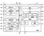
- FIG. 2 is a block diagram showing the overall configuration of the in-vehicle network.
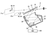
- FIG. 3 is a diagram showing the configuration of the HUD device and the principle of virtual image display.
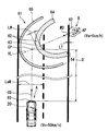
- FIG. 4 is a diagram illustrating an example of a ripple image in the first embodiment.
- FIG. 5 is a diagram for explaining the concept of the ripple image shown in FIG.
- FIG. 6 is a diagram illustrating an example of a ripple image when the moving speed of the notification target changes,
- FIG. 7 is a diagram for explaining the concept of the ripple image shown in FIG. FIG.
- FIG. 8 is a diagram illustrating an example of a ripple image when the traveling speed of the vehicle changes.
- FIG. 9 is a diagram for explaining the concept of the ripple image shown in FIG.
- FIG. 10 is a diagram illustrating an example of a ripple image in the low-attraction mode.
- FIG. 11 is a diagram showing functional blocks constructed in the control circuit.
- FIG. 12 is a flowchart showing processing performed by the control circuit.
- FIG. 13 is a flowchart showing processing performed by the control circuit.
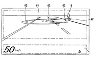
- FIG. 14 is a diagram illustrating an example of a ripple image in the second embodiment.
- FIG. 15 is a diagram for explaining the concept of the ripple image shown in FIG.
- FIG. 16 is a block diagram showing a modification of the in-vehicle network of FIG.
- the HCU 100 is an electronic device mounted on a vehicle A as illustrated in FIGS. 1 and 2.
- the HCU 100 is one of a plurality of nodes provided in the in-vehicle network 1.
- the in-vehicle network 1 includes an external environment recognition system 90, a vehicle control system 80, a display system 10, and a communication bus 85 to which these are connected.
- HCU stands for Human Machine Interface Control Unit, and Human Machine Interface is also called HMI.
- the vehicle A is also called the own vehicle.
- the external environment recognition system 90 includes external sensors such as a front camera unit 92 and a radar unit 93, and a surrounding monitoring ECU 91.
- the external recognition system 90 is for moving objects such as pedestrians, non-human animals, bicycles, motorcycles, and other vehicles, as well as falling objects on the road, traffic signals, guardrails, curbs, road signs, road markings, and trees. Such a stationary object is detected.
- the outside world recognition system 90 can include outside world sensors such as lidar and sonar in addition to the units 92 and 93.
- the front camera unit 92 is, for example, a monocular or compound eye camera installed near the rear mirror of the vehicle A.
- the front camera unit 92 is directed in the traveling direction CD (see FIG. 5) of the vehicle A, and can photograph a range of about 80 meters from the vehicle A with a horizontal viewing angle of about 45 degrees, for example.
- the front camera unit 92 sequentially outputs captured image data showing a moving object and a stationary object to the periphery monitoring ECU 91.
- the radar unit 93 is installed, for example, at the front part of the vehicle A (see FIG. 5).
- the radar unit 93 emits 77 GHz millimeter waves toward the traveling direction CD (see FIG. 5) of the vehicle A from the transmission antenna.
- the radar unit 93 receives millimeter waves emitted from a moving object and a stationary object in the traveling direction CD by a receiving antenna.
- the radar unit 93 can scan a range of about 60 meters from the vehicle A at a horizontal scanning angle of about 55 degrees, for example.
- the radar unit 93 sequentially outputs scanning information based on the received signal to the periphery monitoring ECU 91.
- the periphery monitoring ECU 91 is mainly configured by a microcomputer having a processor and a memory.
- the periphery monitoring ECU 91 is communicably connected to the front camera unit 92, the radar unit 93, and the communication bus 85.
- the peripheral monitoring ECU 91 detects the relative positions of moving objects and stationary objects in the traveling direction CD (see FIG. 5) by integrating the information acquired from the units 92 and 93. Specifically, the periphery monitoring ECU 91 extracts an object shown in the image data of the front camera unit 92 by image processing.
- the periphery monitoring ECU 91 calculates the relative position of the extracted moving object, stationary object, and the like (hereinafter referred to as a detection object) based on the scanning information of the radar unit 93.
- the surroundings monitoring ECU 91 calculates the moving direction MD (see FIG. 5) and moving speed Va (see FIG. 5) of the moving detection object based on the transition of the relative position.
- the periphery monitoring ECU 91 acquires the predicted collision time for the detected object based on the traveling speed Vc of the vehicle A (see FIG. 5) acquired from the communication bus 85 and the calculated relative position of the detected object.
- the collision prediction time is also called Time To Collision (TTC).
- the vehicle control system 80 includes an operation detection sensor such as an accelerator position sensor 82, a brake pedal force sensor 83, and a steering angle sensor 84, and a vehicle control ECU 81.
- the vehicle control system 80 controls the traveling of the vehicle A based on an input by a vehicle occupant (hereinafter referred to as a driver) seated in the driver's seat 17 and a detection result of the external environment recognition system 90.
- the sensors 82 to 84 are connected to the vehicle control ECU 81.
- the accelerator position sensor 82 detects the amount of depression of the accelerator pedal by the driver, and outputs it to the vehicle control ECU 81.
- the brake pedal force sensor 83 detects the pedal force of the brake pedal by the driver and outputs it to the vehicle control ECU 81.
- the steering angle sensor 84 detects the steering angle amount of the steering by the driver and outputs it to the vehicle control ECU 81.
- the vehicle control ECU 81 is mainly composed of a microcomputer having a processor and a memory.
- the vehicle control ECU 81 is connected to the communication bus 85.
- the vehicle control ECU 81 is one or a plurality of types including at least an integrated control ECU among an engine control ECU, a motor control ECU, a brake control ECU, and an integrated control ECU.
- the vehicle control ECU 81 outputs vehicle information such as the detection results of the sensors 82 to 84 and the traveling speed Vc of the vehicle A (see FIG. 5) to the communication bus 85.
- the vehicle control ECU 81 determines whether or not the emergency control condition is satisfied based on the predicted collision time acquired from the communication bus 85.
- the vehicle control ECU 81 realizes collision damage reduction braking that forcibly automatically decelerates the vehicle speed of the vehicle A when the emergency control condition is satisfied.
- the collision damage reduction braking is also called Autonomous Emergency Braking (AEB).
- AEB Autonomous Emergency Braking
- the display system 10 includes a display device such as a head-up display (HUD) device 20, a combination meter 12, and a multifunction display 13, and the HCU 100.
- the display system 10 provides information to the passengers of the vehicle A including the driver.
- the display system 10 can include an operation device that operates display of each display device.
- the HUD device 20 projects light of an image based on data acquired from the HCU 100 onto the windshield 18.
- the light of the image reflected on the vehicle interior side by the windshield 18 is perceived by the driver sitting in the driver's seat 17.
- the driver can visually recognize the virtual image of the image projected by the HUD device 20 by superimposing it on an external scene in front of the vehicle A (hereinafter referred to as foreground).
- the HUD device 20 includes a laser scanner 25, a first screen 26, a second screen 27, and a concave mirror 28.
- the laser scanner 25 irradiates the screens 26 and 27 with laser light.
- the laser scanner 25 scans the laser beam based on the image data acquired from the HCU 100.
- the 1st screen 26, the 2nd screen 27, and the concave mirror 28 are formed by vapor-depositing aluminum on the surface of a resin base material or a glass base material. An image is drawn on the first screen 26 and the second screen 27 by the laser scanner 25.
- Each screen 26, 27 reflects the laser beam emitted from the laser scanner 25 toward the concave mirror 28 while diffusing it.
- the concave mirror 28 is formed in a smooth curved shape with a central portion recessed in a direction away from the screens 26 and 27. The concave mirror 28 enlarges the images on the screens 26 and 27 and projects them on the windshield 18.
- the far display area 21 and the near display area 22 onto which an image is projected by the above HUD device 20 are defined side by side on the windshield 18.
- the distant display area 21 is defined at a position substantially horizontal to the driver's eyes.
- the far display area 21 is projected with the light of the image drawn on the first screen 26.
- the light projected on the distant display area 21 is imaged on a virtual first imaging surface 21a located approximately 15 m ahead of the windshield 18.
- the near display area 22 is defined below the far display area 21.
- the light of the image drawn on the second screen 27 is projected onto the vicinity display area 22.
- the light projected on the vicinity display area 22 is imaged on a virtual second imaging surface 22a located approximately 2 m ahead of the windshield 18.
- the HCU 100 controls the display by these display devices by outputting a control signal to each display device including the HUD device 20 shown in FIG.
- the HCU 100 includes a main processor 31, a drawing processor 32, a rewritable nonvolatile memory 33, an input / output interface 34 for inputting / outputting information, and a control circuit 30 having a bus for connecting them.
- the above display system 10 can notify the driver of a detection object such as a pedestrian detected by the external recognition system 90 as a notification target B (see FIG. 4).
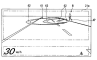
- the notification of the notification target B by the display system 10 is performed by a notification image 60 displayed as a virtual image by the HUD device 20, as shown in FIGS.
- the notification image 60 includes a ripple image 61 projected on the far display area 21 and an icon 69 projected on the near display area 22. Details of the notification image 60 will be described below with reference to FIGS.
- the object to be notified B by the display system 10 is an object whose moving direction MD intersects the traveling direction CD of the vehicle A among detected objects located in the traveling direction CD of the vehicle A. It is.
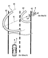
- the ripple image 61 is displayed by being superimposed on the road surface on which the notification target B is located by the HUD device 20 (see FIG. 3).
- the ripple image 61 is subjected to viewpoint conversion so that the virtual mode shown in FIG. 5 is reproduced in the driver's field of view, and projected onto the distant display area 21 as shown in FIG.
- the description relating to the ripple image 61 below mainly indicates the shape of the ripple image 61 before the viewpoint conversion. 4 and 5, the ripple image 61 is an image that spreads from the position AP of the notification target B in the movement direction MD of the notification target B along the road surface.
- the ripple image 61 has a plurality of arc-shaped image portions 62.
- the arcuate image portion 62 is curved in an elliptical arc shape so as to surround the notification target B.
- the major axis of the arcuate image portion 62 substantially coincides with the virtual line VL extending from the position AP of the notification target B along the moving direction MD of the notification target B.
- the curvature of the arcuate image portion 62 increases as it approaches the virtual line VL from both end portions 64 of the arcuate image portion 62.
- the arcuate image portion 62 can indicate the moving direction MD of the notification target B by the central top portion 63 having the maximum curvature.
- the line width LW of the arcuate image portion 62 is defined to be thicker than the line width LT of the lane marking formed on the road surface.
- the line width LW of the arcuate image portion 62 is defined to be thinner than half the lane width LaW (about 2.7 to 3.5 m) of the lane in which the vehicle A travels.
- the interval between the two arcuate image portions 62 on the virtual line VL is secured about half of the lane width LaW.
- the arcuate image unit 62 is repeatedly emitted from the position AP of the notification target B toward the movement direction MD of the notification target B.
- the arcuate image portion 62 superimposed in the vicinity of the position AP of the notification target B has a gradation that becomes lighter as the position AP is approached.
- the arcuate image portion 62 becomes unclear as it approaches the position AP of the notification target B, and becomes clear as it moves away from the notification target B.
- the arcuate image portion 62 moves toward the outer edge 65 of the ripple image 61 while maintaining a distance from another arcuate image portion 62 adjacent in the radial direction.
- the arcuate image portion 62 is enlarged in the radial direction as it moves to the outer edge 65.
- the arcuate image portion 62 is sequentially drawn from the outside by the intersection with the outer edge 65, and disappears while gradually reducing the line width LW.
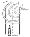
- the ripple image 61 changes the mode according to the states of the notification target B and the vehicle A. As shown in FIGS. 6 and 7, the ripple image 61 changes the position of the outer edge 65 in accordance with the moving speed Va of the notification target B.
- the outer edge 65 of the ripple image 61 is defined at a position farther from the current position AP of the notification target B as the movement speed Va of the notification target B increases. Therefore, the ripple image 61 is displayed larger as the moving speed Va of the notification target B increases.
- Such a ripple image 61 can indicate the range that the notification target B can reach when a predetermined time (for example, 3 seconds) elapses by the position of the outer edge 65.
- the cycle in which the arc-shaped image portion 62 is emitted from the position AP of the notification target B is shortened as the movement speed Va of the notification target B increases.
- the time interval from the time when the movement of one arcuate image portion 62 is started to the time when the movement of the next arcuate image portion 62 is started is shortened.
- the moving speed of the arcuate image portion 62 is increased as the moving speed Va of the notification target B increases.
- the ripple image 61 is reduced in the width direction LR orthogonal to the virtual line VL as the moving speed Va of the notification target B increases.
- each arc-shaped image portion 62 has an elliptical arc shape narrowed in the minor axis direction.
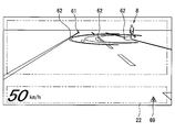
- the ripple image 61 changes the position of the outer edge 65 in accordance with the traveling speed Vc of the vehicle A as shown in FIGS.
- the predetermined time for defining the distance from the position AP of the notification target B to the outer edge 65 is lengthened as the traveling speed Vc becomes slower.
- the ripple image 61 is displayed larger as the traveling speed Vc of the vehicle A is slower.
- the number of arc-shaped image portions 62 included in the ripple image 61 can increase as the traveling speed Vc decreases.
- the display mode of the ripple image 61 is changed to a mode with a low attraction (referred to as a low attraction mode) as illustrated in FIG.
- a low attraction mode a mode with a low attraction
- Each arcuate image portion 62 in the low-attraction mode is displayed with lower brightness and less noticeable hue than the arcuate image portion 62 (see FIG. 4) in the normal mode.
- the display of the ripple image 61 is started in a state in which the notification target B is farther from the vehicle A as the traveling speed Vc of the vehicle A shown in FIG.
- the ripple image 61 is displayed on the basis that the distance D to the virtual intersection position CP is less than the threshold distance.
- the intersection position CP is a position where the traveling direction CD of the vehicle A and the movement direction MD of the notification target B intersect each other.
- the threshold distance is set to a braking distance that can stop the vehicle A with a deceleration of 0.2 G, for example.
- the display color of the ripple image 61 can be changed in order of yellow, amber, and red as the vehicle A approaches the intersection position CP.
- the ripple image 61 may be blinked when the vehicle A approaches the intersection position AP.
- the icon 69 is projected on the vicinity display area 22 as shown in FIG.
- the display of the icon 69 is started after a predetermined time (for example, about 1 second) when the display of the ripple image 61 is started.
- the icon 69 is an image for causing the driver to recognize the presence of the notification target B, similarly to the ripple image 61.
- the icon 69 is displayed in substantially the same color as the arcuate image portion 62.
- control circuit 30 shown in FIGS. 2 and 11 executes a notification program stored in the memory 33 by each of the processors 31 and 32, thereby allowing a plurality of functions.
- Build blocks 41-45 These functional blocks will be described below with reference to FIGS. 2 and 5 based on FIG.
- the image generation unit 41 is a functional block that generates image data of the ripple image 61 and the icon 69 (see FIG. 10).
- the image generation unit 41 determines the display mode of the ripple image 61 and the icon 69 based on the information acquired by the functional blocks 42 to 45.
- the image generation unit 41 generates image data of the ripple image 61 and the icon 69 in the determined mode, and outputs them to the HUD device 20.
- the target information acquisition unit 42 is a functional block that acquires the position information of the detected object including the notification target B output by the external environment recognition system 90 to the communication bus 85, the moving direction MD, and the moving speed Va.
- the own vehicle information acquisition unit 43 is a functional block that acquires information such as the traveling speed Vc of the vehicle A output to the communication bus 85 by the vehicle control system 80.
- the intersection determination unit 44 is a functional block that selects an object to be notified B from detected objects detected by the external environment recognition system 90.
- the intersection determination unit 44 determines whether the moving direction MD of the detected object intersects the traveling direction CD of the vehicle A for the detected object acquired by the target information acquiring unit 42.
- the intersection determination unit 44 sets the detected object that is determined that the moving direction MD and the traveling direction CD intersect each other as the notification target B.
- the operation determination unit 45 is a functional block that determines whether or not an operation for avoiding the notification target B is input by the driver.
- the operation determination unit 45 acquires the operation information output to the communication bus 85 by the vehicle control system 80.
- the operation determination unit 45 determines whether there is an avoidance operation that avoids the notification target B based on the acquired operation information.
- the avoidance operation includes an operation of steering the steering to the side opposite to the notification target B, an operation of loosening the accelerator, an operation of generating a deceleration by braking, and the like.
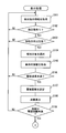
- FIGS. 12 and 13 Details of the display processing of the ripple image 61 and the icon 69 performed by the control circuit 30 will be described based on FIGS. 12 and 13 with reference to FIG.
- the processing shown in the flowcharts of FIGS. 12 and 13 is performed by the control circuit 30 (see FIG. 2) based on the fact that the vehicle A can travel by switching the selector lever 15 (see FIG. 1) to the D range. Repeatedly.
- S101 a process of acquiring detected object information such as the relative position, the moving direction MD, and the moving speed Va from the communication bus 85 (see FIG. 2) is performed, and the process proceeds to S102.
- S102 the presence or absence of the detected object is determined based on whether or not the information of the detected object has been acquired in S101. If it is determined in S102 that there is no detected object, the process returns to S101. On the other hand, if it is determined in S102 that there is a detected object, the process proceeds to S102.
- S103 it is determined whether or not the moving direction MD of the detected object intersects the traveling direction CD of the vehicle A.
- the intersection of the moving direction MD and the traveling direction CD is determined for each detected object. If it is determined in S103 that the moving direction MD of the detected object does not intersect the traveling direction CD, the process returns to S101. On the other hand, if it is determined in S103 that there is a detected object whose movement direction MD intersects the traveling direction CD, the process proceeds to S104.
- a detection object to be notified B is selected from the detection objects, and the process proceeds to S105.
- a predetermined distance for example, about 3 m
- one of the plurality of notification targets B that is closest to the vehicle is selected.
- a process of acquiring information on the vehicle A including the traveling speed Vc and the like from the communication bus 85 (see FIG. 2) is performed, and the process proceeds to S106.
- S106 it is determined whether or not the traveling speed Vc acquired in S105 is less than a threshold speed (for example, 60 km / h). If it is determined in S106 that the traveling speed Vc is equal to or higher than the threshold speed, the process returns to S101. On the other hand, when it determines with driving speed Vc being less than threshold speed in S106, it progresses to S107.
- a threshold speed for example, 60 km / h
- a threshold distance for starting display of the ripple image 61 is set based on the travel speed Vc acquired in S105, and the process proceeds to S108.
- the distance D from the vehicle A to the intersection position CP is calculated based on the position information of the notification target B acquired in S101, and the process proceeds to S109.
- the threshold distance set in S107 is compared with the distance D calculated in S108 to determine whether the distance D is less than the threshold distance. If it is determined in S109 that the relative distance is greater than or equal to the threshold distance, the process of S101 to S108 is repeated to wait for the distance D to fall below the threshold distance. Then, based on the determination that the distance D is less than the threshold distance in S109, the process proceeds to S110.
- the aspect of the ripple image 61 is set based on the information of the notification target B acquired in S101 and the information of the vehicle A acquired in S105, and the process proceeds to S111.
- the projection position and size of the ripple image 61, the emission direction and emission period of the arc-shaped image portion 62, whether or not the low attraction mode is set, and the like are set.
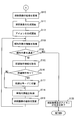
- S111 generation of the ripple image 61 is started, and the process proceeds to S112.
- S112 generation of the icon 69 (see FIG. 10) is started, and the process proceeds to S113.
- the image data of the ripple image 61 and the icon 69 that have been generated in S111 and S112 are sequentially output to the HUD device 20.
- the information of the notification target B is acquired by substantially the same processing as S101, and the process proceeds to S114.
- S114 it is determined whether or not the vehicle A has passed the side of the notification target B based on the relative position information of the notification target B acquired in S113. If it is determined in S114 that the vehicle A has passed the notification target B, the process proceeds to S120.
- S115 when it is determined in S114 that the vehicle A has not passed the notification target B, a process of acquiring information on the avoidance operation by the driver is performed, and the process proceeds to S116.
- S116 the presence / absence of an avoidance operation is determined based on the information acquired in S115. If it is determined in S116 that there is no avoidance operation, the process proceeds to S118.
- S117 the ripple image 61 is switched from the normal mode to the low-attraction mode, and the process proceeds to S118.
- the information of the vehicle A is acquired by substantially the same process as S105, and the process proceeds to S119.
- S119 based on the information of the notification target B acquired in S113 and the information of the vehicle A acquired in S118, a process of updating the aspect of the ripple image 61 is performed, and the process returns to S113.
- the display position, size, hue, and the like of the ripple image 61 are changed.
- the switching to the low attraction mode is reflected in the ripple image 61.
- the ripple image 61 of the first embodiment described so far can indicate the future destination of the notification target B by a shape that extends in the movement direction MD of the notification target B along the road surface. Therefore, a part of the ripple image 61 may overlap with a planned route on which the vehicle A will travel in the future. As a result, the future state of excessive approach between the notification target B and the vehicle A can be implied to the driver. By causing the driver to be aware of crisis by using the ripple image 61, it is possible to increase the certainty of recognition of the notification target B by the driver.
- the ripple image 61 of the first embodiment can accurately indicate a range that can be the future destination of the notification target B by spreading in the movement direction MD in accordance with the movement speed Va of the notification target B.
- the ripple image 61 can further increase the occupant's consciousness of the crisis with respect to the notification target B having a high moving speed Va and prompt the driver to recognize the notification target B.
- the ripple image 61 does not continuously cover the same range of the road surface by the display mode in which the arc-shaped image portion 62 repeatedly emitted from the position AP of the notification target B moves to the outer edge 65. .
- a ripple image 61 it is possible to avoid a situation in which objects falling on the road surface, road markings, and the like are not visually recognized by the driver.
- the ripple image 61 causes the driver to have a high sense of crisis with respect to the quickly moving notification target B by shortening the emission cycle of the arc-shaped image portion 62 in accordance with the moving speed Va of the notification target B. Can be. Therefore, the ripple image 61 makes it possible for the driver to surely recognize the alert target B requiring attention that moves faster than a pedestrian on a bicycle or the like.
- the moving direction MD is less likely to change as the notification target B has a higher moving speed Va. Therefore, in 1st embodiment, the length of the width direction LR of the arc-shaped image part 62 is narrowed according to the moving speed Va of the notification target B. Therefore, the ripple image 61 can indicate the range that can be the future destination of the notification target B without excess or deficiency. As a result, the ripple image 61 can prompt the driver to recognize the notification target B while preventing the driver from feeling excessive crisis.
- the ripple image 61 of the first embodiment can indicate the moving direction MD of the notification target B by the shape of the arc-shaped image portion 62 that increases in curvature as it approaches the top portion 63 that intersects the virtual line VL. Therefore, the driver who perceives the ripple image 61 can easily imagine the approach of the notification target B to the vehicle A and have a sense of crisis.
- the notification by the superimposed display of the ripple image 61 is performed only for the notification target B in which the moving direction MD intersects the traveling direction CD of the vehicle A. Therefore, the situation in which the detected object that the moving direction MD does not cross the traveling direction CD and does not approach the vehicle A and is notified to the driver as the notification target B can be reduced. According to the above, it becomes possible for the display system 10 to perform notification that is difficult for the driver to feel troublesome while improving the certainty of recognizing the notification target B.
- the mode of the ripple image 61 of the first embodiment is changed to the low-attraction mode by inputting an avoidance operation that avoids the notification target B.
- an avoidance operation that avoids the notification target B.
- the ripple image 61 that is reduced as the traveling speed Vc of the vehicle A increases as in the first embodiment can indicate the range that can be the future destination of the notification target B without excess or deficiency.
- the aspect of the ripple image 61 is changed based on the traveling speed Vc, it is possible to prompt the driver to recognize the notification target B while preventing the driver from feeling excessive crisis. .
- the ripple image 61 starts to be superimposed on the notification target B that is located away from the vehicle A. Therefore, the time delay until the vehicle A approaches the notification target B can be ensured even if the traveling speed Vc of the vehicle A increases. As a result, the driver can calmly recognize the notification target B.
- the generation of the ripple image 61 is stopped.
- the notification by the ripple image 61 is not necessary.
- the start of notification at a timing when the driver's avoidance operation is not in time may cause the driver to be confused. Therefore, it is desirable that the notification by the ripple image 61 is limited to a case where the speed is equal to or less than the threshold speed.
- the ripple image 61 notifies one of the plurality of notification targets B that are closer to each other than a predetermined distance, which is closest to the vehicle A. With such notification, a plurality of notification targets B can be collectively recognized by the driver. In addition, a situation in which the position of the notification target B to be recognized due to the overlapping of the plurality of ripple images 61 can be avoided.
- the positional information of the notification target B detected by the external environment recognition system 90 may inevitably shift due to factors such as processing delay and detection error. Therefore, in the first embodiment, the ripple image 61 in the vicinity of the notification target B is made unclear, so that the positional deviation between the notification target B and the ripple image 61 is hardly perceived by the driver. As described above, a situation in which the driver feels uncomfortable due to the positional deviation of the ripple image 61 prevents the driver from quickly recognizing the notification target B is avoided.
- the ripple image 61 of the first embodiment is displayed before the icon 69. Therefore, the driver's line of sight is first guided to the notification target B rather than the icon 69. As described above, by delaying the display start of the icon 69, a situation in which the driver's line of sight is guided to the icon 69 and the recognition of the notification target B by the driver is delayed can be prevented.
- the arc-shaped image portion 62 displayed with a line width LW that is thicker than the white line on the road surface is less likely to be overlooked by the driver.
- the arcuate image portion 62 is displayed with a line width LW that is thinner than half the lane width LaW, so that it is difficult to cover objects falling on the road surface, road markings, and the like. For the above reason, the above range is suitable as the line width LW of the arcuate image portion 62.
- the HCU 100 corresponds to the image generation device of the present disclosure.
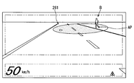
- a ripple image 261 according to the second embodiment of the present disclosure shown in FIGS. 14 and 15 is a modification of the ripple image 61 (see FIG. 4 and the like) of the first embodiment.
- the ripple image 261 is an elliptical image that spreads along the road surface.
- One of the two focal points of the ripple image 261 far from the vehicle A is overlapped with the position AP of the notification target B.
- the long axis of the ripple image 261 is along the moving direction MD of the notification target B.
- the ripple image 261 is enlarged in the radial direction from the vicinity of the notification target B toward the outer edge 265.
- the ripple image 261 disappears once after being enlarged to the outer edge 265.
- the ripple image 261 is enlarged again from the vicinity of the notification target B toward the outer edge 265.
- the ripple image 261 notifies the driver of the notification target B by the animation display that repeats the above aspect change.
- the ripple image 261 is displayed more unclearly as it approaches the position AP of the notification target B due to the gradation attached in the vicinity of the notification target B.
- the ripple image 261 changes its shape according to the states of the notification target B and the vehicle A, as in the first embodiment. Specifically, the ripple image 261 increases in the movement direction MD and narrows in the width direction LR as the movement speed Va of the notification target B increases.
- the display cycle of the ripple image 261 that repeatedly expands and disappears toward the outer edge 265 is shortened as the moving speed Va of the notification target B increases. Further, the ripple image 261 is enlarged as the traveling speed Vc of the vehicle A is slower.
- the ripple image 261 can make the driver aware of the crisis by producing the same effect as the first embodiment. As a result, it is possible to increase the certainty of recognition of the notification target B by the driver.
- the functions provided by the processors 31 and 32 of the control circuit 30 can be provided by hardware and software different from those described above, or a combination thereof.
- the HCU is omitted.
- An image projected by the HUD device 320 is generated by an image generation circuit 330 provided in the HUD device 320.
- images displayed on the combination meter 12 and the multifunction display 13 are generated by an image generation circuit provided in these components.
- the image generation circuit 330 corresponds to the control circuit 30 (see FIG. 2) of the first embodiment, and includes a main processor 31, a drawing processor 32, a memory 33, an input / output interface 34, and the like.
- the image generation circuit 330 can acquire information output on the communication bus 85 by the external environment recognition system 90 and the vehicle control system 80 and generate a ripple image.
- the image generation circuit 330 corresponds to the image generation device of the present disclosure.
- the information of the notification target B in the above embodiment has been detected by the external sensor of the external recognition system 90.
- the information on the notification target B acquired by the HCU 100 (see FIG. 2) and the image generation circuit 330 is not limited to the information detected by the external environment recognition system 90.
- the information about the notification target B received by inter-vehicle communication may be acquired by the HCU 100 and the image generation circuit 330.
- the inter-vehicle communication is performed between the vehicle-mounted device 130 mounted on the vehicle A and the portable terminal 110 etc. possessed by a pedestrian or the like.
- the portable terminal 110 and the vehicle-mounted device 130 can perform transmission / reception of information by wireless communication using, for example, a wireless LAN or Bluetooth (registered trademark).
- the on-vehicle device 130 acquires current position information from the mobile terminal 110.
- the vehicle-mounted device 130 or the image generation circuit 330 can calculate the relative position of a pedestrian or the like who carries the mobile terminal 110 by comparing the current position information of the vehicle A and the position information of the mobile terminal 110. According to the above-described communication between pedestrians, the HCU 100 (see FIG.
- the image generation circuit 330 acquire information on the notification target B even when a pedestrian or the like exists outside the detection range of the external sensor. be able to. Furthermore, the information of the notification target B may be provided to the vehicle A not only by the inter-vehicle communication but also by the road-to-vehicle communication.
- the ripple image 61 in the above embodiment was formed on the first image plane 21a located about 15 m ahead of the windshield 18 (see FIG. 3).
- the position where the ripple image is formed is not limited to the position of the first image plane.
- the ripple image may be formed at a position of about 2 m ahead of the windshield 18 as with the icon.
- the position where the ripple image is formed may be changeable within a range of 2 to 15 m, for example.
- the display mode of the ripple image is changed according to the moving speed Va of the notification target B and the traveling speed Vc of the vehicle A.
- the display mode of the ripple image may be constant regardless of the moving speed Va and the traveling speed Vc.
- a highly attractive display mode of the ripple image may be maintained.
- the display of the ripple image may be stopped when an avoidance operation is input.
- the arc-shaped image portion of the first embodiment was formed in an elliptical arc shape and enlarged in the radial direction as it moved to the outer edge.
- the arcuate image portion may be an arcuate shape that curves with a certain curvature.
- the arcuate image portion may be in a display mode that moves in the movement direction MD while maintaining the shape.
- the arcuate image portion may be divided into a plurality of parts in the circumferential direction.
- the line width LW of the arcuate image portion may be made thicker or thinner as it approaches the outer edge of the ripple image.
- the reduction of the ripple image in the width direction LR as the moving speed Va increases may be realized by reducing the central angle of the arc-shaped image portion.
- the ripple image expresses the spread in the movement direction MD by the movement of the arcuate image portion moving from the position AP of the notification target B to the outer edge.
- the ripple image of the second embodiment expresses the spread in the movement direction MD by the movement that is enlarged toward the outer edge.
- the spread in the movement direction MD can be expressed even with a ripple image of a still image without such animation.
- the ripple image can express the spread in the movement direction MD by adding a change in brightness or shade of light and shade along the movement direction MD, that is, gradation.
- the ripple image of the above embodiment is displayed in such a manner as to move on the road surface, but may be displayed in a manner such as moving a predetermined height from the road surface, for example.
- the ripple image can be superimposed and displayed on the road surface without a sense of incongruity.
- the detection unit where the movement direction MD intersects the traveling direction CD is selected as the notification target B.
- all detected objects detected in the traveling direction CD of the vehicle A may be set as the notification target B.
- the notification target B when there are a plurality of notification targets B within a predetermined distance, not the one closest to the vehicle A but the fastest one of the moving speeds Va approaching the vehicle A is selected as the notification target B. Good.
- the ripple image of the above embodiment was stopped when the traveling speed Vc exceeded the threshold speed.
- the upper threshold speed can be changed as appropriate.
- the lower limit threshold speed is set, and the ripple image display may be stopped while the vehicle is traveling at the traveling speed Vc lower than the lower limit threshold speed. These threshold speeds may not be set.
- the threshold distance at which the display of the ripple image is adjusted according to the traveling speed Vc can be constant. With such a setting, the display of the ripple image is started when the distance D from the vehicle A to the intersection position CP is less than the predetermined threshold distance regardless of the traveling speed Vc.
- the vicinity of the notification target of the ripple image is displayed in gradation so as not to reveal the error in position detection of the notification target B or the like.
- the positional deviation between the notification target and the ripple image may be made ambiguous by devising the shape and color of the ripple image different from the gradation.
- the ripple image may be displayed clearly even in the vicinity of the notification target.
- each step is expressed as, for example, S101. Further, each step can be divided into a plurality of sub-steps, while a plurality of steps can be combined into one step.
Abstract
画像生成装置は、車両(A)の進行方向に位置する報知対象(B)を当該車両の乗員に報知する画像を生成し、当該画像の虚像を車両の前景に重畳表示させるヘッドアップディスプレイ装置(20)へ出力する。画像生成装置は、報知対象の位置情報及び移動方向を取得する対象情報取得部と、少なくとも一つの位置情報が対象情報取得部によって取得された場合に、報知対象が位置する路面にヘッドアップディスプレイ装置によって重ねて表示され、当該報知対象の位置から路面に沿って移動方向に広がる波紋画像(61)、を生成する画像生成部と、を備える。
Description
本出願は、2015年3月16日に出願された日本国特許出願2015-52356号に基づくものであり、その開示をここに参照により援用する。
本開示は、車両の進行方向に位置する報知対象を画像によって車両の乗員に報知する技術に関する。
従来、例えば特許文献1のように、ヘッドアップディスプレイ装置によって車両の前景に虚像を重畳表示することにより、歩行者等の障害物を運転者に報知する技術が知られている。この特許文献1では、障害物の位置に向けて画像を移動させる視線誘導表示の実施により、運転者の視線が、障害物に誘導されている。
特許文献1に開示された表示は、障害物等の報知対象の現在位置を単に示しているに過ぎない。即ち、車両の予定進路上に報知対象が移動するといった将来の様子は、表示によって何ら暗示され得ない。そのため、運転者に危機意識を抱かせることができず、報知対象に運転者の視線を向けさせたとしても、運転者による報知対象の認識が行われないままとなってしまうおそれがあった。
本開示は、運転者等の車両乗員による報知対象の認識の確実性を高めることが可能な技術を提供することを目的とする。
本開示の一例による画像生成装置は、車両の進行方向に位置する報知対象を当該車両の乗員に報知する画像を生成し、当該画像の虚像を車両の前景に重畳表示させるヘッドアップディスプレイ装置へ出力する。画像生成装置は、報知対象の位置情報及び移動方向を取得する対象情報取得部と、少なくとも一つの位置情報が対象情報取得部によって取得された場合に、報知対象が位置する路面にヘッドアップディスプレイ装置によって重ねて表示され、当該報知対象の位置から路面に沿って移動方向に広がる波紋画像、を生成する画像生成部と、を備える。
本開示における波紋画像は、路面に沿って報知対象の移動方向に拡がる形状により、報知対象の将来の移動先を示すことができる。故に、波紋画像の一部は、車両が将来走行する予定進路と重なり得る。報知対象と車両との過度な接近という将来の様子が車両の乗員に暗示され得る。波紋画像によって乗員に危機意識を抱かせることにより、当該乗員による報知対象の認識の確実性を高めることが可能となる。
本開示についての上記および他の目的、特徴や利点は、添付の図面を参照した下記の詳細な説明から、より明確になる。添付図面において、
図1は、車両における運転席周辺のレイアウトを示す図であり、
図2は、車載ネットワークの全体構成を示すブロック図であり、
図3は、HUD装置の構成及び虚像表示の原理を示す図であり、
図4は、第一実施形態における波紋画像の一例を示す図であり、
図5は、図4に示す波紋画像の概念を説明するための図であり、
図6は、報知対象の移動速度が変化した場合の波紋画像の一例を示す図であり、
図7は、図6に示す波紋画像の概念を説明するための図であり、
図8は、車両の走行速度が変化した場合の波紋画像の一例を示す図であり、
図9は、図8に示す波紋画像の概念を説明するための図であり、
図10は、低誘目モードとされた波紋画像の一例を示す図であり、
図11は、制御回路に構築される機能ブロックを示す図であり、
図12は、制御回路によって実施される処理を示すフローチャートであり、
図13は、制御回路によって実施される処理を示すフローチャートであり、
図14は、第二実施形態における波紋画像の一例を示す図であり、
図15は、図14に示す波紋画像の概念を説明するための図であり、
図16は、図2の車載ネットワークの変形例を示すブロック図である。
以下、本開示の複数の実施形態を図面に基づいて説明する。尚、各実施形態において対応する構成要素には同一の符号を付すことにより、重複する説明を省略する場合がある。各実施形態において構成の一部分のみを説明している場合、当該構成の他の部分については、先行して説明した他の実施形態の構成を適用することができる。また、各実施形態の説明において明示している構成の組み合わせばかりではなく、特に組み合わせに支障が生じなければ、明示していなくても複数の実施形態の構成同士を部分的に組み合わせることができる。そして、複数の実施形態及び変形例に記述された構成同士の明示されていない組み合わせも、以下の説明によって開示されているものとする。
(第一実施形態)
本開示の第一実施形態のHCU100は、図1及び図2に示すように、車両Aに搭載される電子装置である。HCU100は、車載ネットワーク1に設けられた複数のノードのうちの一つとなる。車載ネットワーク1は、外界認識システム90、車両制御システム80、表示システム10、及びこれらが接続される通信バス85等によって構成されている。HCUは、Human Machine Interface Control Unitを表し、Human Machine InterfaceはHMIとも呼ばれる。車両Aは自車両とも呼ぶ。
本開示の第一実施形態のHCU100は、図1及び図2に示すように、車両Aに搭載される電子装置である。HCU100は、車載ネットワーク1に設けられた複数のノードのうちの一つとなる。車載ネットワーク1は、外界認識システム90、車両制御システム80、表示システム10、及びこれらが接続される通信バス85等によって構成されている。HCUは、Human Machine Interface Control Unitを表し、Human Machine InterfaceはHMIとも呼ばれる。車両Aは自車両とも呼ぶ。
外界認識システム90は、前方カメラユニット92及びレーダユニット93等の外界センサと、周辺監視ECU91とを備えている。外界認識システム90は、歩行者、人間以外の動物、自転車、オートバイ、及び他の車両のような移動物体、さらに路上の落下物、交通信号、ガードレール、縁石、道路標識、道路標示、及び樹木のような静止物体を検出する。外界認識システム90は、各ユニット92,93に加えて、ライダ及びソナー等の外界センサを備えることが可能である。
前方カメラユニット92は、例えば車両Aのバックミラー近傍に設置された単眼式、又は複眼式のカメラである。前方カメラユニット92は、車両Aの進行方向CD(図5参照)を向けられており、例えば約45度程度の水平視野角度で車両Aから約80メートルの範囲を撮影できる。前方カメラユニット92は、移動物体及び静止物体が写る撮像画像のデータを、周辺監視ECU91へ逐次出力する。
レーダユニット93は、例えば車両Aのフロント部に設置されている(図5参照)。レーダユニット93は、77GHz帯のミリ波を送信アンテナから車両Aの進行方向CD(図5参照)に向けて放出する。レーダユニット93は、進行方向CDの移動物体及び静止物体等で射されたミリ波を、受信アンテナによって受信する。レーダユニット93は、例えば約55度程度の水平走査角度で車両Aから約60メートルの範囲を走査できる。レーダユニット93は、受信信号に基づく走査情報を周辺監視ECU91へ逐次出力する。
周辺監視ECU91は、プロセッサ及びメモリを有するマイクロコンピュータを主体として構成されている。周辺監視ECU91は、前方カメラユニット92及びレーダユニット93、並びに通信バス85と通信可能に接続されている。周辺監視ECU91は、各ユニット92,93から取得した情報を統合することにより、進行方向CD(図5参照)にある移動物体及び静止物体等の相対位置を検出する。具体的に、周辺監視ECU91は、前方カメラユニット92の画像データに写る物体を画像処理によって抽出する。そして周辺監視ECU91は、抽出した移動物体及び静止物体等(以下、検出物と称する)の相対位置をレーダユニット93の走査情報に基づいて算出する。周辺監視ECU91は、相対位置の推移に基づいて、移動している検出物の移動方向MD(図5参照)及び移動速度Va(図5参照)を演算する。周辺監視ECU91は、通信バス85から取得する車両Aの走行速度Vc(図5参照)と、算出した検出物の相対位置とに基づいて、この検出物に対する衝突予測時間を取得する。衝突予測時間は、Time To Collision(TTC)とも呼ぶ。
車両制御システム80は、アクセルポジションセンサ82、ブレーキ踏力センサ83、及び操舵角センサ84等の操作検出センサと、車両制御ECU81とを備えている。車両制御システム80は、運転席17に着座した車両の乗員(以下、運転者と呼ぶ)による入力と、外界認識システム90の検出結果とに基づいて、車両Aの走行を制御する。
各センサ82~84は、車両制御ECU81に接続されている。アクセルポジションセンサ82は、運転者によるアクセルペダルの踏み込み量を検出し、車両制御ECU81へ出力する。ブレーキ踏力センサ83は、運転者によるプレーキペダルの踏力を検出し、車両制御ECU81へ出力する。操舵角センサ84は、運転者によるステアリングの舵角量を検出し、車両制御ECU81へ出力する。
車両制御ECU81は、プロセッサ及びメモリを有するマイクロコンピュータを主体として構成されている。車両制御ECU81は、通信バス85に接続されている。車両制御ECU81は、エンジン制御ECU、モータ制御ECU、ブレーキ制御ECU、及び統合制御ECU等のうち、統合制御ECUを少なくとも含む一種類又は複数種類である。車両制御ECU81は、各センサ82~84の検出結果及び車両Aの走行速度Vc(図5参照)等の車両情報を、通信バス85に出力する。車両制御ECU81は、通信バス85から取得した衝突予測時間に基づいて、緊急制御条件の成立の可否を判定する。車両制御ECU81は、緊急制御条件が成立した場合に、車両Aの車速を強制的に自動減速する衝突被害軽減制動を実現する。衝突被害軽減制動は、Autonomous Emergency Braking(AEB)とも呼ぶ。
表示システム10は、Head-Up Display(HUD)装置20、コンビネーションメータ12、及びマルチファンクションディスプレイ13等の表示デバイスと、HCU100とを備えている。表示システム10は、運転者を含む車両Aの乗員に情報を提供する。表示システム10は、各表示デバイスの表示を操作する操作デバイスを備えることが可能である。
図1及び図3に示すHUD装置20は、車両Aの車室内にて、インストルメントパネル19内に設置されている。HUD装置20は、HCU100から取得したデータに基づく画像の光を、ウインドシールド18に投影する。ウインドシールド18によって車室内側に反射された画像の光は、運転席17に着座する運転者によって知覚される。運転者は、HUD装置20によって投影された画像の虚像を、車両Aの前方の外界風景(以下、前景と呼ぶ)と重ねて視認可能となる。こうした前景への重畳表示を実現するため、HUD装置20は、レーザスキャナ25、第一スクリーン26、第二スクリーン27、及び凹面鏡28を有している。
レーザスキャナ25は、各スクリーン26,27にレーザ光を照射する。レーザスキャナ25は、HCU100から取得した画像データに基づいてレーザ光を走査する。第一スクリーン26、第二スクリーン27、及び凹面鏡28は、樹脂基材又はガラス基材の表面にアルミニウムを蒸着させることで形成されている。第一スクリーン26及び第二スクリーン27上には、レーザスキャナ25によって画像が描画される。各スクリーン26,27は、レーザスキャナ25から照射されたレーザ光を拡散させつつ、凹面鏡28に向けて反射させる。凹面鏡28は、各スクリーン26,27から遠ざかる方向に中心部を凹ませた円滑な湾曲形状に形成されている。凹面鏡28は、各スクリーン26,27上の画像を拡大して、ウインドシールド18に投影する。
以上のHUD装置20によって画像を投影される遠方表示領域21及び近傍表示領域22がウインドシールド18に上下に並んで規定されている。遠方表示領域21は、運転者の目と概ね水平な位置に規定されている。遠方表示領域21には、第一スクリーン26に描画された画像の光が投影される。遠方表示領域21に投影された光は、ウインドシールド18よりも15m程度前方に位置する仮想の第一結像面21aで結像される。近傍表示領域22は、遠方表示領域21の下方に規定されている。近傍表示領域22には、第二スクリーン27に描画された画像の光が投影される。近傍表示領域22に投影された光は、ウインドシールド18よりも2m程度前方に位置する仮想の第二結像面22aで結像される。
HCU100は、図2に示すHUD装置20を含む各表示デバイスに制御信号を出力することにより、これら表示デバイスによる表示を制御する。HCU100は、メインプロセッサ31、描画プロセッサ32、書き換え可能な不揮発性のメモリ33、情報の入出力を行う入出力インターフェース34、及びこれらを接続するバス等を有する制御回路30を備えている。
以上の表示システム10は、外界認識システム90によって検出された歩行者等の検出物を、報知対象B(図4参照)として運転者に報知することができる。表示システム10による報知対象Bの報知は、図1及び図3に示すように、HUD装置20によって虚像表示される報知画像60により実施される。報知画像60には、遠方表示領域21に投影される波紋画像61と、近傍表示領域22に投影されるアイコン69とが含まれている。以下、報知画像60の詳細を、図4~図10に基づいて説明する。尚、表示システム10(図2参照)が報知対象Bとする物体は、車両Aの進行方向CDに位置する検出物のうちで、移動方向MDが車両Aの進行方向CDと交差している物体である。
波紋画像61は、図4に示すように、報知対象Bが位置する路面にHUD装置20(図3参照)によって重ねて表示される。波紋画像61は、図5に示す仮想の態様が運転者の視界にて再現されるように視点変換されて、図4の如く遠方表示領域21に投影される。以下の波紋画像61に係る記述は、主に視点変換前の波紋画像61の形状を示している。図4及び図5に示すように、波紋画像61は、報知対象Bの位置APから、路面に沿って、報知対象Bの移動方向MDに広がる画像である。波紋画像61は、複数の弧状画像部62を有している。
弧状画像部62は、報知対象Bを囲むよう楕円弧状に湾曲している。弧状画像部62の長軸は、報知対象Bの位置APから、報知対象Bの移動方向MDに沿って伸びる仮想線VLと実質一致している。弧状画像部62の曲率は、当該弧状画像部62の両端部64から仮想線VLに近づくに従い、大きくなっている。弧状画像部62は、曲率が最大となる中央の頂部63により、報知対象Bの移動方向MDを示すことができる。弧状画像部62の線幅LWは、路面上に形成された区画線の線幅LTよりも太くなるよう規定されている。弧状画像部62の線幅LWは、車両Aの走行する車線の車線幅LaW(約2.7~3.5m)の半分よりも細くなるよう規定されている。仮想線VL上における二つの弧状画像部62間の間隔は、車線幅LaWの半分程度確保されている。
弧状画像部62は、報知対象Bの位置APから、報知対象Bの移動方向MDへ向かって繰り返し射出される。報知対象Bの位置APの近傍に重畳された弧状画像部62には、位置APに近づくに従って淡くなるグラデーションが付けられている。弧状画像部62は、報知対象Bの位置APに近づくほど不鮮明となり、報知対象Bから離れるに従って鮮明となる。弧状画像部62は、径方向に隣接する他の弧状画像部62との間の間隔を保ちつつ、波紋画像61の外縁65に向かって移動する。弧状画像部62は、外縁65への移動に伴って径方向に拡大される。弧状画像部62は、外縁65との交差によって外側から順に描画を中止され、次第に線幅LWを細くしつつ消失する。
波紋画像61は、報知対象B及び車両Aそれぞれの状態に応じて、態様を変化させる。波紋画像61は、図6及び図7に示すように、報知対象Bの移動速度Vaに応じて外縁65の位置を変化させる。波紋画像61の外縁65は、報知対象Bの移動速度Vaが速いほど、報知対象Bの現在の位置APから離れた位置に規定される。故に、波紋画像61は、報知対象Bの移動速度Vaが速くなるに従って大きく表示される。こうした波紋画像61は、所定時間(例えば3秒)の経過時に報知対象Bが到達可能な範囲を、外縁65の位置によって示すことができる。
波紋画像61において、報知対象Bの位置APから弧状画像部62が射出される周期は、報知対象Bの移動速度Vaが速いほど、短くされる。これにより、一つの弧状画像部62の移動が開始された時点から、次の弧状画像部62の移動が開始される時点までの時間間隔は、短くなる。加えて弧状画像部62の移動速度は、報知対象Bの移動速度Vaが速くなるに従って、速くされる。さらに波紋画像61は、報知対象Bの移動速度Vaが速くなるに従って、仮想線VLと直交する幅方向LRにおいて縮小される。その結果、各弧状画像部62は、短軸方向に狭められた楕円弧状となる。
波紋画像61は、図8及び図9に示すように、車両Aの走行速度Vcに応じて外縁65の位置を変化させる。報知対象Bの位置APから外縁65までの距離を規定する所定時間は、走行速度Vcが遅くなるに従って長くされる。その結果、波紋画像61は、車両Aの走行速度Vcが遅いほど、大きく表示される。また、波紋画像61に含まれる弧状画像部62の数は、走行速度Vcが遅くなるほど、多くなり得る。
波紋画像61は、移動方向MDが進行方向CDと交差すると判定された報知対象Bに対応する画像のみが生成される。また、波紋画像61の表示態様は、報知対象Bに対する回避操作が運転者によって入力された場合に、図10に示すように、誘目性の低い態様(低誘目モードと呼ぶ)に変更される。低誘目モードにおける各弧状画像部62は、通常モードにおける弧状画像部62(図4参照)よりも低い輝度、且つ、目立ち難い色合いにて表示される。
波紋画像61の表示は、図5に示す車両Aの走行速度Vcが速いほど、報知対象Bが車両Aから離れている状態で開始される。波紋画像61は、仮想の交差位置CPまでの距離Dが閾値距離未満となったことに基づいて、表示を開始される。交差位置CPは、車両Aの進行方向CDと報知対象Bの移動方向MDとが互いに交差する位置である。閾値距離は、例えば0.2Gの減速度で車両Aを停止させることが可能な制動距離に設定されている。表示システム10(図2参照)は、交差位置CPまでの距離Dが0.4Gの減速度で車両Aを停止させることが可能な制動距離を下回ると、波紋画像61による報知に加えて、音声による報知を実施する。そして、交差位置CPまでの距離が0.8Gの減速度で車両Aを停止させることが可能な距離を下回ると、緊急制御条件の成立に基づいて、AEBによる自動減速が開始される。波紋画像61の表示色は、車両Aが交差位置CPに近づくに従い、イエロー、アンバー、レッドといった順に変化させることが可能である。加えて波紋画像61は、車両Aの交差位置APへの接近により、点滅表示されてもよい。
アイコン69は、図10に示すように、近傍表示領域22に投影される。アイコン69の表示は、波紋画像61の表示が開始された所定時間(例えば1秒程度)後に、開始される。アイコン69は、波紋画像61と同様に、報知対象Bの存在を運転者に認識させるための画像である。アイコン69は、弧状画像部62と実質同一の色合いで表示される。
ここまで説明した波紋画像61及びアイコン69を表示するため、図2及び図11に示す制御回路30は、メモリ33に記憶された報知プログラムを各プロセッサ31,32によって実行することで、複数の機能ブロック41~45を構築する。これらの機能ブロックを、図11に基づき、図2及び図5を参照しつつ以下説明する。
画像生成部41は、波紋画像61及びアイコン69(図10参照)の画像データを生成する機能ブロックである。画像生成部41は、機能ブロック42~45によって取得される情報に基づき、波紋画像61及びアイコン69の表示態様を決定する。画像生成部41は、決定した態様の波紋画像61及びアイコン69の画像データを生成し、HUD装置20へ出力する。
対象情報取得部42は、外界認識システム90によって通信バス85に出力された報知対象Bを含む検出物の位置情報、移動方向MD、及び移動速度Vaを取得する機能ブロックである。自車情報取得部43は、車両制御システム80によって通信バス85に出力された車両Aの走行速度Vc等の情報を取得する機能ブロックである。
交差判定部44は、外界認識システム90によって検出された検出物の中から、報知対象Bとする物体を選択する機能ブロックである。交差判定部44は、対象情報取得部42によって取得された検出物について、当該検出物の移動方向MDが車両Aの進行方向CDと交差しているか否かを判定する。交差判定部44は、移動方向MDと進行方向CDとが交差していると判定した検出物を、報知対象Bとする。
操作判定部45は、運転者によって報知対象Bを回避する操作が入力されたか否かを判定する機能ブロックである。操作判定部45は、車両制御システム80によって通信バス85に出力された操作情報を取得する。操作判定部45は、取得した操作情報に基づいて、報知対象Bを回避するような回避操作の有無を判定する。回避操作には、ステアリングを報知対象Bとは反対側に操舵する操作、アクセルを緩める操作、ブレーキによって減速度を発生させる操作等が含まれる。
次に、制御回路30によって実施される波紋画像61及びアイコン69の表示処理の詳細を、図12及び図13に基づき、図5を参照しつつ説明する。図12及び図13のフローチャートに示される処理は、セレクターレバー15(図1参照)のDレンジへの切り替えにより車両Aが走行可能になったことに基づいて、制御回路30(図2参照)によって繰り返し実施される。
S101では、相対位置、移動方向MD、及び移動速度Vaといった検出物の情報を通信バス85(図2参照)から取得する処理を実施し、S102に進む。S102では、S101にて検出物の情報を取得できたか否かに基づいて、検出物の有無を判定する。S102にて、検出物が無いと判定した場合、S101に戻る。一方で、S102にて、検出物が有ると判定した場合、S102に進む。
S103では、検出物の移動方向MDが車両Aの進行方向CDと交差しているか否かを判定する。複数の検出物の情報を取得していた場合には、個々の検出物に対して、移動方向MDと進行方向CDとの交差を判定する。S103にて、検出物の移動方向MDが進行方向CDと交差していないと判定した場合には、S101に戻る。一方で、S103にて、移動方向MDが進行方向CDと交差する検出物が有ると判定した場合には、S104に進む。
S104では、検出物の中から、報知対象Bとする検出物を選択し、S105に進む。所定距離(例えば3m程度)よりも互いに近接した複数の報知対象Bの位置情報が取得されていた場合のS104では、複数の報知対象Bのうちで車両に最も近接する一つを選択する。S105では、走行速度Vc等を含む車両Aの情報を通信バス85(図2参照)から取得する処理を実施し、S106に進む。
S106では、S105にて取得した走行速度Vcが閾値速度(例えば60km/h)未満であるか否かを判定する。S106にて、走行速度Vcが閾値速度以上であると判定した場合、S101に戻る。一方で、S106にて、走行速度Vcが閾値速度未満であると判定した場合、S107に進む。
S107では、S105にて取得した走行速度Vcに基づいて、波紋画像61の表示を開始する閾値距離を設定し、S108に進む。S108では、S101にて取得した報知対象Bの位置情報に基づき、車両Aから交差位置CPまでの距離Dを算出し、S109に進む。S109では、S107にて設定した閾値距離と、S108にて算出した距離Dとを比較し、距離Dが閾値距離未満か否かを判定する。S109にて、相対距離が閾値距離以上であると判定した場合、S101~S108の処理を繰り返すことにより、距離Dが閾値距離を下回るのを待つ。そして、S109にて、距離Dが閾値距離未満となったと判定したことに基づいて、S110に進む。
S110では、S101にて取得した報知対象Bの情報、及びS105にて取得した車両Aの情報に基づいて、波紋画像61の態様を設定し、S111に進む。S110では、波紋画像61の投影位置及び大きさ、弧状画像部62の射出方向及び射出周期、並びに低誘目モードか否か等が設定される。
S111では、波紋画像61の生成を開始し、S112に進む。S112では、アイコン69(図10参照)の生成を開始して、S113に進む。S111及びS112にて生成が開始された波紋画像61及びアイコン69の各画像データは、HUD装置20に逐次出力される。S113では、S101と実質同一の処理によって報知対象Bの情報を取得し、S114に進む。S114では、S113にて取得した報知対象Bの相対位置情報に基づいて、車両Aが報知対象Bの側方を通過したか否かを判定する。S114にて、車両Aが報知対象Bを通過したと判定した場合、S120に進む。
S114にて、車両Aが報知対象Bを通過していないと判定した場合のS115では、運転者による回避操作の情報を取得する処理を実施し、S116に進む。S116では、S115にて取得した情報に基づいて、回避操作の有無を判定する。S116にて、回避操作が無かったと判定した場合、S118に進む。一方で、S116にて、回避操作が有ったと判定した場合、S117に進む。S117では、波紋画像61を通常モードから低誘目モードに切り替える処理を行い、S118に進む。
S118では、S105と実質同一の処理によって車両Aの情報を取得し、S119に進む。S119では、S113にて取得した報知対象Bの情報、及びS118にて取得した車両Aの情報に基づいて、波紋画像61の態様を更新する処理を実施し、S113に戻る。S119により、波紋画像61の表示位置、大きさ、及び色合い等が変化する。加えてS119では、低誘目モードへの切り替えが波紋画像61に反映される。
S114にて、車両Aが報知対象Bを通過したと判定した場合のS120では、波紋画像61及びアイコン69の生成を終了する処理を行い、再びS101に戻る。S120により、波紋画像61及びアイコン69は、実質同時に表示を中止される。
ここまで説明した第一実施形態の波紋画像61は、路面に沿って報知対象Bの移動方向MDに拡がる形状により、報知対象Bの将来の移動先を示すことができる。故に、波紋画像61の一部は、車両Aが将来走行する予定進路と重なり得る。その結果、報知対象Bと車両Aとの過度な接近という将来の様子が運転者に暗示され得る。こうした波紋画像61によって運転者に危機意識を抱かせることにより、運転者による報知対象Bの認識の確実性を高めることが可能となる。
加えて第一実施形態の波紋画像61は、報知対象Bの移動速度Vaに応じて移動方向MDへ広がることにより、報知対象Bの将来の移動先となり得る範囲を適確に示し得る。その結果、波紋画像61は、移動速度Vaの速い報知対象Bに対する乗員の危機意識をいっそう高めて、報知対象Bの認識を運転者に促すことができる。
また第一実施形態のように、報知対象Bの位置APから繰り返し射出される弧状画像部62が外縁65へ移動する表示態様により、波紋画像61は、路面の同じ範囲を継続して覆い隠さない。このような波紋画像61であれば、路面への落下物及び道路標示等が運転者に視認されなくなる事態は、回避可能となる。
さらに第一実施形態では、報知対象Bの移動速度Vaに合わせて弧状画像部62の射出周期を短くすることにより、波紋画像61は、速く移動する報知対象Bに対する高い危機意識を運転者に惹起させ得る。故に波紋画像61は、自転車等に搭乗して歩行者よりも速く移動する要注意な報知対象Bを、運転者に確実に認識させることが可能となる。
ここで、移動速度Vaの高い報知対象Bほど、移動方向MDは変化し難い。故に第一実施形態では、報知対象Bの移動速度Vaに合わせて、弧状画像部62の幅方向LRの長さが狭められている。故に、波紋画像61は、報知対象Bの将来の移動先となり得る範囲を過不足なく示し得る。その結果、波紋画像61は、過度の危機意識を運転者に抱かせることを防ぎつつ、運転者に報知対象Bの認識を促すことが可能となる。
また第一実施形態の波紋画像61は、仮想線VLと交差する頂部63に近づくほど曲率を大きくする弧状画像部62の形状により、報知対象Bの移動方向MDを示し得る。故に、波紋画像61を知覚した運転者は、報知対象Bの車両Aへの接近を容易に想像し、危機意識を抱くことができる。
さらに第一実施形態によれば、移動方向MDが車両Aの進行方向CDと交差している報知対象Bに限って、波紋画像61の重畳表示による報知は行われる。故に、移動方向MDが進行方向CDと交差せず、車両Aに近づいてこない検出物が報知対象Bとして運転者に報知される事態は、低減され得る。以上によれば、表示システム10は、報知対象Bを認識させる確実性を高めつつ、運転者にとって煩わしく感じられ難い報知を実施することが可能となる。
加えて第一実施形態の波紋画像61は、報知対象Bを回避する回避操作の入力によって、低誘目モードに態様を変更される。こうして波紋画像61の誘目性を下げることにより、回避操作を行った運転者に報知対象Bを報知し続けて、煩わしさを感じさせてしまう事態は、回避され得る。加えて、波紋画像61を完全に消してしまわないことで、報知対象Bが無くなったと運転者に誤解を与える事態も、回避され得る。
また走行速度Vcが速いほど、所定の時間内で報知対象Bが移動できる範囲は、狭くなる。故に、第一実施形態の如く車両Aの走行速度Vcの上昇に伴って小さくされる波紋画像61は、報知対象Bの将来の移動先となり得る範囲を過不足なく示し得る。このように、走行速度Vcに基づいて波紋画像61の態様を変更すれば、過度の危機意識を運転者に抱かせることを防ぎつつ、運転者に報知対象Bの認識を促すことが可能となる。
さらに第一実施形態では、車両Aの走行速度Vcが速くなるほど、車両Aから離れて位置する報知対象Bに対して波紋画像61の重畳が開始される。故に、車両Aが報知対象Bに近づくまでの時間的な猶予は、車両Aの走行速度Vcが上昇しても確保され得る。その結果、運転者は、報知対象Bを落ち着いて認識することが可能となる。
加えて第一実施形態では、予め規定された閾値速度を超えた場合、波紋画像61の生成は、中止される。高速での走行が可能な自動車専用道路には、報知対象Bとなるような歩行者及び自転車等は、実質存在し得ない。故に、波紋画像61による報知は不要となる。また、運転者の回避操作が間に合わないようなタイミングでの報知開始は、運転者をかえって混乱させる虞がある。故に、波紋画像61による報知は、閾値速度以下の場合に限られるのが望ましい。
また第一実施形態では、所定距離よりも互いに近接している複数の報知対象Bのうちで車両Aに最も近接する一つが波紋画像61によって報知される。こうした報知であれば、複数の報知対象Bは、運転者に纏めて認識され得る。加えて、複数の波紋画像61が重なり合うことにより、認識すべき報知対象Bの位置が不明確になる事態も、回避され得る。
さらに、外界認識システム90にて検出される報知対象Bの位置情報には、処理の遅れ及び検出誤差といった要因により、不可避的にずれが生じ得る。故に第一実施形態では、報知対象B近傍の波紋画像61を不鮮明にすることで、報知対象Bと波紋画像61との位置ずれは、運転者に知覚され難くなっている。以上により、波紋画像61の位置ずれによる違和感が運転者による報知対象Bの迅速な認識を妨げてしまう事態は、回避される。
加えて第一実施形態の波紋画像61は、アイコン69よりも先に表示される。故に、運転者の視線は、アイコン69よりも報知対象Bにまず誘導される。以上のように、アイコン69の表示開始を遅らせることで、アイコン69に運転者の視線が誘導されて運転者の報知対象Bの認識を遅らせてしまう事態は、防がれ得る。
また第一実施形態のように、路面上の白線よりも太い線幅LWにて表示される弧状画像部62は、運転者によって見落とされ難くなる。加えて弧状画像部62は、車線幅LaWの半分の長さよりも細い線幅LWにて表示されることにより、路面への落下物及び道路標示等を覆い隠し難くなる。以上の理由から、弧状画像部62の線幅LWとしては、上記の範囲が好適なのである。尚、第一実施形態では、HCU100が、本開示の画像生成装置に相当する。
(第二実施形態)
図14及び図15に示す本開示の第二実施形態による波紋画像261は、第一実施形態の波紋画像61(図4等参照)の変形例である。波紋画像261は、路面に沿って広がる楕円形状の画像である。波紋画像261の二つの焦点のうちで車両Aから遠い一方が、報知対象Bの位置APと重ねられている。波紋画像261の長軸は、報知対象Bの移動方向MDに沿っている。以上の形状及び配置により、波紋画像261は、報知対象Bの位置APから、当該報知対象Bの移動方向MDに広がっている。
図14及び図15に示す本開示の第二実施形態による波紋画像261は、第一実施形態の波紋画像61(図4等参照)の変形例である。波紋画像261は、路面に沿って広がる楕円形状の画像である。波紋画像261の二つの焦点のうちで車両Aから遠い一方が、報知対象Bの位置APと重ねられている。波紋画像261の長軸は、報知対象Bの移動方向MDに沿っている。以上の形状及び配置により、波紋画像261は、報知対象Bの位置APから、当該報知対象Bの移動方向MDに広がっている。
波紋画像261は、報知対象Bの近傍から、外縁265へ向けて径方向に拡大される。波紋画像261は、外縁265まで拡大された後、一旦消失する。そして波紋画像261は、再び報知対象Bの近傍から、外縁265へ向けて拡大される。以上の態様変化を繰り返すアニメーション表示により、波紋画像261は、報知対象Bを運転者に報知する。
波紋画像261は、報知対象Bの近傍に付けられたグラデーションにより、報知対象Bの位置APに近づくほど不鮮明に表示される。加えて波紋画像261は、第一実施形態と同様に、報知対象B及び車両Aそれぞれの状態に応じて形状を変化させる。具体的に、波紋画像261は、報知対象Bの移動速度Vaが速いほど、移動方向MDに大きくされ且つ幅方向LRに狭くされる。また、外縁265へ向けての拡大と消失を繰り返す波紋画像261の表示周期は、報知対象Bの移動速度Vaが速いほど、短くされる。さらに、波紋画像261は、車両Aの走行速度Vcが遅いほど、大きくされる。
ここまで説明した第二実施形態でも、波紋画像261は、第一実施形態と同様の効果を奏することにより、運転者に危機意識を抱かせることができる。その結果、運転者による報知対象Bの認識の確実性を高めることが可能となる。
(他の実施形態)
以上、本開示による複数の実施形態について説明したが、本開示は、上記実施形態に限定して解釈されるものではなく、本開示の要旨を逸脱しない範囲内において種々の実施形態及び組み合わせに適用することができる。
以上、本開示による複数の実施形態について説明したが、本開示は、上記実施形態に限定して解釈されるものではなく、本開示の要旨を逸脱しない範囲内において種々の実施形態及び組み合わせに適用することができる。
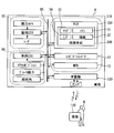
上記実施形態において、制御回路30の各プロセッサ31,32によって提供されていた機能は、上述のものとは異なるハードウェア及びソフトウェア、或いはこれらの組み合わせによって提供可能である。例えば、図16に示す変形例の表示システム310では、HCUが省略されている。HUD装置320によって投影される画像は、HUD装置320内に設けられた画像生成回路330によって生成される。同様に、コンビネーションメータ12及びマルチファンクションディスプレイ13それぞれに表示される画像は、これらの構成内に設けられた画像生成回路によって生成される。
画像生成回路330は、第一実施形態の制御回路30(図2参照)に相当し、メインプロセッサ31、描画プロセッサ32、メモリ33、入出力インターフェース34等を有している。画像生成回路330は、外界認識システム90及び車両制御システム80によって通信バス85上に出力された情報を取得し、波紋画像を生成することが可能である。以上の変形例では、画像生成回路330が、本開示の画像生成装置に相当する。
上記実施形態における報知対象Bの情報は、外界認識システム90の外界センサによって検出されていた。しかし、HCU100(図2参照)及び画像生成回路330に取得される報知対象Bの情報は、外界認識システム90によって検出された情報に限定されない。例えば、歩車間通信によって受信した報知対象Bの情報が、HCU100及び画像生成回路330によって取得されてもよい。
歩車間通信は、車両Aに搭載された車載器130と、歩行者等の所持する携帯端末110等との間にて実施される。携帯端末110と車載器130とは、例えば無線LAN又はBluetooth(登録商標)等による無線通信によって情報の送受信を行うことができる。車載器130は、携帯端末110から現在の位置情報を取得する。車載器130又は画像生成回路330は、車両Aの現在の位置情報と、携帯端末110の位置情報とを比較することにより、携帯端末110を所持する歩行者等の相対位置を算出可能である。以上の歩車間通信の採用によれば、外界センサの検出範囲外に歩行者等が存在している場合でも、HCU100(図2参照)及び画像生成回路330は、報知対象Bの情報を取得することができる。さらに、歩車間通信に限らず、路車間通信によって報知対象Bの情報が車両Aにもたらされてもよい。
上記実施形態における波紋画像61は、ウインドシールド18の前方約15mに位置する第一結像面21aに結像されていた(図3参照)。しかし、波紋画像の結像される位置は、第一結像面の位置に限定されない。例えば波紋画像は、アイコンと同様に、ウインドシールド18の前方約2mの位置に結像されてもよい。さらに、波紋画像の結像される位置は、例えば2~15mの範囲で変更可能であってもよい。
上記実施形態では、報知対象Bの移動速度Va及び車両Aの走行速度Vcに応じて、波紋画像の表示態様が変更されていた。しかし、波紋画像の表示態様は、移動速度Va及び走行速度Vcに係わらず一定であってもよい。また、回避操作が入力された場合でも、波紋画像の誘目性の高い表示態様が維持されてもよい。さらに、波紋画像の表示は、回避操作が入力された場合に中止されてもよい。
上記第一実施形態の弧状画像部は、楕円弧状に形成され、外縁への移動に伴って径方向に拡大されていた。しかし、弧状画像部は、一定の曲率で湾曲する円弧状であってもよい。また、弧状画像部は、形状を維持したまま移動方向MDへ移動する表示態様であってもよい。さらに、弧状画像部は、周方向において複数に分割された形態であってもよい。また、弧状画像部の線幅LWは、波紋画像の外縁に近づくほど太く又は細くされてもよい。さらに、移動速度Vaの増加に伴う波紋画像の幅方向LRへの縮小は、弧状画像部の中心角を小さくすることによって実現されてもよい。
上記第一実施形態では、報知対象Bの位置APから外縁へ移動する弧状画像部の動きによって、波紋画像は、移動方向MDへの広がりを表現していた。また、上記第二実施形態の波紋画像は、外縁へ向けて拡大される動きによって移動方向MDへの広がりを表現していた。しかし、こうしたアニメーションを伴わない静止画による波紋画像でも、移動方向MDへの広がりは表現可能である。具体的には、移動方向MDに沿った輝度又は色合いの濃淡の変化、即ちグラデーションが付けられることにより、波紋画像は、移動方向MDへの広がりを表現することができる。
上記実施形態の波紋画像は、路面上を移動するような態様で表示されていたが、例えば路面から所定高さを移動しているような態様で表示されてもよい。こうした表示形態であれば、報知対象B近傍の路面に段差や傾斜があった場合でも、波紋画像は、路面に違和感無く重畳表示され得る。
上記実施形態では、移動方向MDが進行方向CDと交差する検出部が、報知対象Bとして選別されていた。しかし、車両Aの進行方向CDにて検出された検出物が全て報知対象Bに設定されてもよい。また、所定距離内に複数の報知対象Bが存在している場合においては、車両Aに最も近い一つではなく、車両Aへ近づく移動速度Vaの最も速い一つが、報知対象Bとして選択されてよい。
上記実施形態の波紋画像は、走行速度Vcが閾値速度を超えると、表示を中止されていた。こうした上限の閾値速度は、適宜変更可能である。さらに、下限の閾値速度が設定されており、下限の閾値速度を下回る走行速度Vcでの走行中は、波紋画像の表示が中止されてもよい。尚、これらの閾値速度は、設定されていなくてもよい。
上記実施形態にて、波紋画像の表示が開始される閾値距離は、走行速度Vcに応じて調整されていた。しかし、閾値距離は、一定とすることが可能である。こうした設定であれば、走行速度Vcに係わらず、車両Aから交差位置CPまでの距離Dが所定の閾値距離を下回ることで、波紋画像の表示は開始される。
上記実施形態では、報知対象Bの位置検出の誤差等を顕在化させないために、波紋画像の報知対象近傍は、グラデーション表示されていた。しかし、グラデーションとは異なる波紋画像の形状や色合いの工夫によって、報知対象と波紋画像との位置ずれが曖昧にされていてもよい。また、報知対象Bの検出精度及び演算速度が十分に高ければ、波紋画像は、報知対象近傍でも鮮明に表示されてよい。
なお、本出願に記載されるフローチャート、あるいは、フローチャートの処理は、複数のステップ(あるいはセクションとも言及される)から構成され、各ステップは、たとえば、S101と表現される。さらに、各ステップは、複数のサブステップに分割されることができる、一方、複数のステップが合わさって一つのステップにすることも可能である。
以上、本開示に係る画像生成装置の実施形態および構成を例示したが、本開示に係る実施の形態および構成は、上述した各実施の形態および各構成に限定されるものではない。異なる実施の形態および構成にそれぞれ開示された技術的要素を適宜組み合わせて得られる実施の形態および構成についても本開示に係る実施の形態および構成の範囲に含まれる。
Claims (15)
- 車両(A)の進行方向(CD)に位置する報知対象(B)を当該車両の乗員に報知する画像を生成し、当該画像の虚像を前記車両の前景に重畳表示させるヘッドアップディスプレイ装置(20)へ出力する画像生成装置であって、
前記報知対象の位置情報及び移動方向(MD)を取得する対象情報取得部(42)と、
少なくとも一つの前記位置情報が前記対象情報取得部によって取得された場合に、前記報知対象が位置する路面に前記ヘッドアップディスプレイ装置によって重ねて表示され、当該報知対象の位置から前記路面に沿って前記移動方向に広がる波紋画像(61,261)、を生成する画像生成部(41)と、を備える画像生成装置。 - 前記対象情報取得部は、前記報知対象の移動速度を取得し、
前記画像生成部は、前記報知対象の前記移動速度が速いほど、前記波紋画像を大きくする請求項1に記載の画像生成装置。 - 前記波紋画像(61)は、前記報知対象を囲むよう弧状に湾曲し、当該報知対象の位置から前記移動方向へ向かって繰り返し射出されるよう表示される弧状画像部(62)、を含む請求項1又は2に記載の画像生成装置。
- 前記対象情報取得部は、前記報知対象の移動速度を取得し、
前記画像生成部は、前記報知対象の前記移動速度が速いほど、前記弧状画像部が射出される周期を短くする請求項3に記載の画像生成装置。 - 前記画像生成部は、前記報知対象の位置から前記移動方向に伸びる仮想線(VL)に近づくほど、曲率が大きくなる前記弧状画像部を描画する請求項3又は4に記載の画像生成装置。
- 前記対象情報取得部は、前記報知対象の移動速度を取得し、
前記画像生成部は、前記報知対象の前記移動速度が速いほど、前記移動方向と交差する幅方向(LR)において前記波紋画像を狭める請求項1~5のいずれか一項に記載の画像生成装置。 - 前記移動方向が前記進行方向と交差するか否かに基づいて、前記車両の前記進行方向に位置する物体の中から、前記報知対象を選択する交差判定部(44)、をさらに備え、
前記画像生成部は、前記交差判定部によって選択された前記報知対象を報知する前記波紋画像を生成する請求項1~6のいずれか一項に記載の画像生成装置。 - 前記乗員によって前記報知対象を回避する操作が入力されたか否かを判定する操作判定部(45)、をさらに備え、
前記画像生成部は、前記操作判定部によって回避操作が入力されたと判定されたことに基づいて、前記波紋画像を誘目性の低い態様に変更する請求項1~7のいずれか一項に記載の画像生成装置。 - 前記車両の走行速度を取得する自車情報取得部(43)、をさらに備える請求項1~8のいずれか一項に記載の画像生成装置。
- 前記画像生成部は、前記車両の走行速度が遅いほど、前記波紋画像を大きくする請求項9に記載の画像生成装置。
- 前記画像生成部は、前記車両の走行速度が速いほど、前記報知対象が前記車両から離れている状態で前記波紋画像の生成を開始する請求項9又は10に記載の画像生成装置。
- 前記画像生成部は、前記車両の走行速度が予め規定された閾値速度を超える場合に、前記波紋画像の生成を中止する請求項9~11のいずれか一項に記載の画像生成装置。
- 前記画像生成部は、所定距離よりも互いに近接した複数の前記報知対象の前記位置情報が前記対象情報取得部によって取得された場合に、複数の前記報知対象のうちで前記車両に最も近い一つを報知する前記波紋画像を生成する請求項1~12のいずれか一項に記載の画像生成装置。
- 前記画像生成部は、前記報知対象から離れるに従って鮮明となる前記波紋画像を生成する請求項1~13のいずれか一項に記載の画像生成装置。
- 前記画像生成部は、前記波紋画像の生成を開始した後に、前記報知対象の存在を報知するアイコン(69)の生成を開始する請求項1~14のいずれか一項に記載の画像生成装置。
Priority Applications (2)
| Application Number | Priority Date | Filing Date | Title |
|---|---|---|---|
| DE112016001259.4T DE112016001259B4 (de) | 2015-03-16 | 2016-02-12 | Bilderzeugungsvorrichtung |
| US15/558,407 US10748425B2 (en) | 2015-03-16 | 2016-02-12 | Image generation apparatus |
Applications Claiming Priority (2)
| Application Number | Priority Date | Filing Date | Title |
|---|---|---|---|
| JP2015-052356 | 2015-03-16 | ||
| JP2015052356A JP6372402B2 (ja) | 2015-03-16 | 2015-03-16 | 画像生成装置 |
Publications (1)
| Publication Number | Publication Date |
|---|---|
| WO2016147547A1 true WO2016147547A1 (ja) | 2016-09-22 |
Family
ID=56919932
Family Applications (1)
| Application Number | Title | Priority Date | Filing Date |
|---|---|---|---|
| PCT/JP2016/000720 WO2016147547A1 (ja) | 2015-03-16 | 2016-02-12 | 画像生成装置 |
Country Status (4)
| Country | Link |
|---|---|
| US (1) | US10748425B2 (ja) |
| JP (1) | JP6372402B2 (ja) |
| DE (1) | DE112016001259B4 (ja) |
| WO (1) | WO2016147547A1 (ja) |
Cited By (1)
| Publication number | Priority date | Publication date | Assignee | Title |
|---|---|---|---|---|
| CN111164652A (zh) * | 2017-10-02 | 2020-05-15 | 堪得拉日本株式会社 | 移动体图像生成记录显示装置和程序 |
Families Citing this family (36)
| Publication number | Priority date | Publication date | Assignee | Title |
|---|---|---|---|---|
| JP2016001464A (ja) * | 2014-05-19 | 2016-01-07 | 株式会社リコー | 処理装置、処理システム、処理プログラム、及び、処理方法 |
| JP6726674B2 (ja) * | 2015-10-15 | 2020-07-22 | マクセル株式会社 | 情報表示装置 |
| CN108349503B (zh) * | 2015-10-30 | 2022-08-02 | 三菱电机株式会社 | 驾驶辅助装置 |
| IL246386B (en) * | 2016-06-22 | 2018-03-29 | Tarantula Tech Ltd | A device for identifying dangerous objects located at a certain distance from a surface |
| JP7009057B2 (ja) | 2016-11-15 | 2022-01-25 | 株式会社リコー | 表示装置、表示システム、及びプログラム |
| JP6699528B2 (ja) * | 2016-12-05 | 2020-05-27 | 株式会社デンソー | 車両用表示制御装置及び車両用表示システム |
| JP6520905B2 (ja) * | 2016-12-19 | 2019-05-29 | トヨタ自動車株式会社 | 車両用運転支援装置 |
| WO2018147066A1 (ja) * | 2017-02-08 | 2018-08-16 | 株式会社デンソー | 車両用表示制御装置 |
| JP6699646B2 (ja) * | 2017-02-08 | 2020-05-27 | 株式会社デンソー | 車両用表示制御装置 |
| EP3413288A1 (en) * | 2017-06-09 | 2018-12-12 | Honda Research Institute Europe GmbH | Method for assisting a person in acting in a dynamic environment and corresponding system |
| JP6805974B2 (ja) * | 2017-06-29 | 2020-12-23 | アイシン・エィ・ダブリュ株式会社 | 走行支援装置及びコンピュータプログラム |
| JP7065383B2 (ja) * | 2017-06-30 | 2022-05-12 | パナソニックIpマネジメント株式会社 | 表示システム、情報提示システム、表示システムの制御方法、プログラム、及び移動体 |
| WO2019065045A1 (ja) | 2017-09-26 | 2019-04-04 | 株式会社日立国際電気 | 物体捜索システム、物体捜索装置、及び物体捜索方法 |
| JP6958630B2 (ja) * | 2017-11-17 | 2021-11-02 | 株式会社アイシン | 車両運転補助システム、車両運転補助方法、及び車両運転補助プログラム |
| JP7007055B2 (ja) * | 2017-11-20 | 2022-01-24 | アルパイン株式会社 | 自動運転システム |
| DE112018006514T5 (de) * | 2017-12-21 | 2020-09-24 | Nippon Seiki Co., Ltd. | Verfahren zum Steuern der Anzeige, Vorrichtung zum Steuern der Anzeige und Head-up-Display |
| JP7077616B2 (ja) * | 2017-12-28 | 2022-05-31 | トヨタ自動車株式会社 | 表示制御装置および表示制御方法 |
| US11127295B2 (en) * | 2018-01-23 | 2021-09-21 | Board Of Trustees Of Michigan State University | Visual sensor fusion and data sharing across connected vehicles for active safety |
| DE102018203121B4 (de) * | 2018-03-02 | 2023-06-22 | Volkswagen Aktiengesellschaft | Verfahren zur Berechnung einer AR-Einblendung von Zusatzinformationen für eine Anzeige auf einer Anzeigeeinheit, Vorrichtung zur Durchführung des Verfahrens sowie Kraftfahrzeug und Computerprogramm |
| JP6933189B2 (ja) * | 2018-05-29 | 2021-09-08 | 株式会社デンソー | 表示制御装置、及び表示制御プログラム |
| JP7279318B2 (ja) * | 2018-08-30 | 2023-05-23 | 株式会社リコー | 制御装置、投射制御システム、移動体制御システム、移動体、制御方法及び制御プログラム |
| CN111284325B (zh) * | 2018-12-10 | 2022-04-15 | 博泰车联网科技(上海)股份有限公司 | 车辆、车机设备及其车辆沿途对象详尽信息显示方法 |
| DE102019202586A1 (de) * | 2019-02-26 | 2020-08-27 | Volkswagen Aktiengesellschaft | Verfahren zum Betreiben eines Fahrerinformationssystems in einem Ego-Fahrzeug und Fahrerinformationssystem |
| DE102019202581B4 (de) | 2019-02-26 | 2021-09-02 | Volkswagen Aktiengesellschaft | Verfahren zum Betreiben eines Fahrerinformationssystems in einem Ego-Fahrzeug und Fahrerinformationssystem |
| DE102019202588A1 (de) | 2019-02-26 | 2020-08-27 | Volkswagen Aktiengesellschaft | Verfahren zum Betreiben eines Fahrerinformationssystems in einem Ego-Fahrzeug und Fahrerinformationssystem |
| JP2020144417A (ja) * | 2019-03-04 | 2020-09-10 | アイシン・エィ・ダブリュ株式会社 | リスク取得システム、リスク表示システムおよびリスク取得プログラム |
| JP7250571B2 (ja) * | 2019-03-11 | 2023-04-03 | 本田技研工業株式会社 | 倒立振子型ロボット |
| WO2020213105A1 (ja) * | 2019-04-17 | 2020-10-22 | 日本電気株式会社 | 画像提示装置、画像提示方法、及びプログラムが格納された非一時的なコンピュータ可読媒体 |
| JP6921156B2 (ja) * | 2019-10-15 | 2021-08-18 | ソフトバンク株式会社 | 情報処理装置、報知システム、プログラム及び報知方法 |
| DE102019218256A1 (de) * | 2019-11-26 | 2021-05-27 | Volkswagen Aktiengesellschaft | Sicherheitseinrichtung und Verfahren zur Warnung fahrzeugexterner Objekte |
| JP2021109824A (ja) * | 2020-01-14 | 2021-08-02 | Agc株式会社 | ディスプレイ用カバーガラス、車載表示装置、および、ディスプレイ用カバーガラスの製造方法 |
| US11351961B2 (en) * | 2020-01-29 | 2022-06-07 | Ford Global Technologies, Llc | Proximity-based vehicle security systems and methods |
| JPWO2022024962A1 (ja) * | 2020-07-27 | 2022-02-03 | ||
| US11836870B1 (en) * | 2021-01-19 | 2023-12-05 | United Services Automobile Association (Usaa) | Systems and methods for virtual physical distancing |
| DE102021202666A1 (de) * | 2021-03-18 | 2022-09-22 | Volkswagen Aktiengesellschaft | Dynamischer AR-Hinweis |
| US20230401873A1 (en) * | 2022-06-14 | 2023-12-14 | Snap Inc. | Ar assisted safe cycling |
Citations (3)
| Publication number | Priority date | Publication date | Assignee | Title |
|---|---|---|---|---|
| JP2007087337A (ja) * | 2005-09-26 | 2007-04-05 | Toyota Motor Corp | 車輌周囲情報表示装置 |
| JP2007133644A (ja) * | 2005-11-10 | 2007-05-31 | Hino Motors Ltd | 歩行者認識装置 |
| JP2013203103A (ja) * | 2012-03-27 | 2013-10-07 | Denso It Laboratory Inc | 車両用表示装置、その制御方法及びプログラム |
Family Cites Families (13)
| Publication number | Priority date | Publication date | Assignee | Title |
|---|---|---|---|---|
| JPH08233594A (ja) | 1995-02-27 | 1996-09-13 | Aqueous Res:Kk | 車載用ナビゲーションシステム |
| JP4389276B2 (ja) | 1997-10-21 | 2009-12-24 | マツダ株式会社 | 車両の障害物警報装置 |
| JP2003291688A (ja) | 2002-04-03 | 2003-10-15 | Denso Corp | 表示方法、運転支援装置、プログラム |
| JP4244684B2 (ja) * | 2003-04-10 | 2009-03-25 | 三菱自動車工業株式会社 | 車両用監視装置 |
| DE102008042539A1 (de) | 2008-10-01 | 2010-04-08 | Robert Bosch Gmbh | Verfahren zur Anzeige eines Warnhinweises in einem Fahrzeug |
| JP5392470B2 (ja) | 2009-01-30 | 2014-01-22 | マツダ株式会社 | 車両用表示装置 |
| DE102011117297A1 (de) * | 2011-11-01 | 2013-05-02 | Volkswagen Aktiengesellschaft | Verfahren zum Betreiben eines Fahrerassistenzsystems und dazugehöriges Fahrerassistenzsystem |
| DE102012210445A1 (de) | 2012-06-20 | 2013-12-24 | Continental Automotive Gmbh | Head-up-Display |
| JP5492962B2 (ja) | 2012-09-28 | 2014-05-14 | 富士重工業株式会社 | 視線誘導システム |
| JP6176478B2 (ja) | 2013-04-26 | 2017-08-09 | 日本精機株式会社 | 車両情報投影システム |
| JP2015052356A (ja) | 2013-09-06 | 2015-03-19 | パナソニック株式会社 | 断熱パネル及び断熱パネルの製造方法 |
| US9690104B2 (en) * | 2014-12-08 | 2017-06-27 | Hyundai Motor Company | Augmented reality HUD display method and device for vehicle |
| WO2016092591A1 (ja) | 2014-12-09 | 2016-06-16 | 三菱電機株式会社 | 衝突リスク算出装置、衝突リスク表示装置、車体制御装置 |
-
2015
- 2015-03-16 JP JP2015052356A patent/JP6372402B2/ja active Active
-
2016
- 2016-02-12 DE DE112016001259.4T patent/DE112016001259B4/de active Active
- 2016-02-12 US US15/558,407 patent/US10748425B2/en active Active
- 2016-02-12 WO PCT/JP2016/000720 patent/WO2016147547A1/ja active Application Filing
Patent Citations (3)
| Publication number | Priority date | Publication date | Assignee | Title |
|---|---|---|---|---|
| JP2007087337A (ja) * | 2005-09-26 | 2007-04-05 | Toyota Motor Corp | 車輌周囲情報表示装置 |
| JP2007133644A (ja) * | 2005-11-10 | 2007-05-31 | Hino Motors Ltd | 歩行者認識装置 |
| JP2013203103A (ja) * | 2012-03-27 | 2013-10-07 | Denso It Laboratory Inc | 車両用表示装置、その制御方法及びプログラム |
Cited By (3)
| Publication number | Priority date | Publication date | Assignee | Title |
|---|---|---|---|---|
| CN111164652A (zh) * | 2017-10-02 | 2020-05-15 | 堪得拉日本株式会社 | 移动体图像生成记录显示装置和程序 |
| EP3693930A4 (en) * | 2017-10-02 | 2021-06-30 | Candera Japan Inc. | MOBILE BODY IMAGE PRODUCTION / RECORDING / DISPLAY DEVICE, AND PROGRAM |
| CN111164652B (zh) * | 2017-10-02 | 2023-12-08 | 加贺富仪艾股份有限公司 | 移动体图像生成记录显示装置和程序产品 |
Also Published As
| Publication number | Publication date |
|---|---|
| JP6372402B2 (ja) | 2018-08-15 |
| JP2016172469A (ja) | 2016-09-29 |
| DE112016001259T5 (de) | 2017-11-30 |
| US10748425B2 (en) | 2020-08-18 |
| US20180090007A1 (en) | 2018-03-29 |
| DE112016001259B4 (de) | 2023-06-29 |
Similar Documents
| Publication | Publication Date | Title |
|---|---|---|
| JP6372402B2 (ja) | 画像生成装置 | |
| US10800258B2 (en) | Vehicular display control device | |
| JP7074432B2 (ja) | 車両制御システム、車両制御方法、および車両制御プログラム | |
| US11008016B2 (en) | Display system, display method, and storage medium | |
| JP4807263B2 (ja) | 車両用表示装置 | |
| JP6447468B2 (ja) | 運転支援装置 | |
| EP3106838B1 (en) | Display apparatus for vehicle | |
| CN108973682B (zh) | 车辆控制系统、车辆控制方法及存储介质 | |
| CN110709304B (zh) | 车辆控制系统、车辆控制方法及存储介质 | |
| US20180198955A1 (en) | Vehicle-use image display system and method | |
| US11016497B2 (en) | Vehicle control system, vehicle control method, and vehicle control program | |
| JP2016197407A (ja) | 情報提示装置 | |
| JP2006227811A (ja) | 運転支援装置 | |
| CN110603166A (zh) | 车辆控制系统、车辆控制方法及车辆控制程序 | |
| WO2022044768A1 (ja) | 車両用表示装置 | |
| CN113165513A (zh) | 平视显示器、车辆用显示系统以及车辆用显示方法 | |
| WO2019038914A1 (ja) | 表示制御装置、表示制御方法およびプログラム | |
| JP2017007481A (ja) | 車載ヘッドアップディスプレイ装置及び車載表示システム | |
| JP2017041126A (ja) | 車載表示制御装置、車載表示制御方法 | |
| WO2016157892A1 (ja) | 情報提示装置 | |
| JP2019011055A (ja) | 運転支援装置 | |
| JP2018167834A (ja) | 画像生成装置 | |
| JP7363833B2 (ja) | 提示制御装置、提示制御プログラム、自動走行制御システムおよび自動走行制御プログラム | |
| WO2017138343A1 (ja) | 運転教示装置 | |
| WO2021132259A1 (en) | Display apparatus, display method, and program |
Legal Events
| Date | Code | Title | Description |
|---|---|---|---|
| 121 | Ep: the epo has been informed by wipo that ep was designated in this application |
Ref document number: 16764381 Country of ref document: EP Kind code of ref document: A1 |
|
| WWE | Wipo information: entry into national phase |
Ref document number: 15558407 Country of ref document: US |
|
| WWE | Wipo information: entry into national phase |
Ref document number: 112016001259 Country of ref document: DE |
|
| 122 | Ep: pct application non-entry in european phase |
Ref document number: 16764381 Country of ref document: EP Kind code of ref document: A1 |