WO2016143481A1 - 電力変換器の同期制御装置 - Google Patents
電力変換器の同期制御装置 Download PDFInfo
- Publication number
- WO2016143481A1 WO2016143481A1 PCT/JP2016/054794 JP2016054794W WO2016143481A1 WO 2016143481 A1 WO2016143481 A1 WO 2016143481A1 JP 2016054794 W JP2016054794 W JP 2016054794W WO 2016143481 A1 WO2016143481 A1 WO 2016143481A1
- Authority
- WO
- WIPO (PCT)
- Prior art keywords
- command value
- axis
- phase
- axis current
- value
- Prior art date
- Legal status (The legal status is an assumption and is not a legal conclusion. Google has not performed a legal analysis and makes no representation as to the accuracy of the status listed.)
- Ceased
Links
Images










Classifications
-
- H—ELECTRICITY
- H02—GENERATION; CONVERSION OR DISTRIBUTION OF ELECTRIC POWER
- H02P—CONTROL OR REGULATION OF ELECTRIC MOTORS, ELECTRIC GENERATORS OR DYNAMO-ELECTRIC CONVERTERS; CONTROLLING TRANSFORMERS, REACTORS OR CHOKE COILS
- H02P1/00—Arrangements for starting electric motors or dynamo-electric converters
- H02P1/16—Arrangements for starting electric motors or dynamo-electric converters for starting dynamo-electric motors or dynamo-electric converters
- H02P1/46—Arrangements for starting electric motors or dynamo-electric converters for starting dynamo-electric motors or dynamo-electric converters for starting an individual synchronous motor
-
- H—ELECTRICITY
- H02—GENERATION; CONVERSION OR DISTRIBUTION OF ELECTRIC POWER
- H02M—APPARATUS FOR CONVERSION BETWEEN AC AND AC, BETWEEN AC AND DC, OR BETWEEN DC AND DC, AND FOR USE WITH MAINS OR SIMILAR POWER SUPPLY SYSTEMS; CONVERSION OF DC OR AC INPUT POWER INTO SURGE OUTPUT POWER; CONTROL OR REGULATION THEREOF
- H02M7/00—Conversion of AC power input into DC power output; Conversion of DC power input into AC power output
- H02M7/42—Conversion of DC power input into AC power output without possibility of reversal
- H02M7/44—Conversion of DC power input into AC power output without possibility of reversal by static converters
- H02M7/48—Conversion of DC power input into AC power output without possibility of reversal by static converters using discharge tubes with control electrode or semiconductor devices with control electrode
-
- H—ELECTRICITY
- H02—GENERATION; CONVERSION OR DISTRIBUTION OF ELECTRIC POWER
- H02P—CONTROL OR REGULATION OF ELECTRIC MOTORS, ELECTRIC GENERATORS OR DYNAMO-ELECTRIC CONVERTERS; CONTROLLING TRANSFORMERS, REACTORS OR CHOKE COILS
- H02P1/00—Arrangements for starting electric motors or dynamo-electric converters
- H02P1/16—Arrangements for starting electric motors or dynamo-electric converters for starting dynamo-electric motors or dynamo-electric converters
- H02P1/42—Arrangements for starting electric motors or dynamo-electric converters for starting dynamo-electric motors or dynamo-electric converters for starting an individual single-phase induction motor
-
- H—ELECTRICITY
- H02—GENERATION; CONVERSION OR DISTRIBUTION OF ELECTRIC POWER
- H02P—CONTROL OR REGULATION OF ELECTRIC MOTORS, ELECTRIC GENERATORS OR DYNAMO-ELECTRIC CONVERTERS; CONTROLLING TRANSFORMERS, REACTORS OR CHOKE COILS
- H02P21/00—Arrangements or methods for the control of electric machines by vector control, e.g. by control of field orientation
- H02P21/34—Arrangements for starting
-
- H—ELECTRICITY
- H02—GENERATION; CONVERSION OR DISTRIBUTION OF ELECTRIC POWER
- H02P—CONTROL OR REGULATION OF ELECTRIC MOTORS, ELECTRIC GENERATORS OR DYNAMO-ELECTRIC CONVERTERS; CONTROLLING TRANSFORMERS, REACTORS OR CHOKE COILS
- H02P27/00—Arrangements or methods for the control of AC motors characterised by the kind of supply voltage
- H02P27/04—Arrangements or methods for the control of AC motors characterised by the kind of supply voltage using variable-frequency supply voltage, e.g. inverter or converter supply voltage
- H02P27/06—Arrangements or methods for the control of AC motors characterised by the kind of supply voltage using variable-frequency supply voltage, e.g. inverter or converter supply voltage using DC to AC converters or inverters
Definitions
- the present invention starts a motor using a power converter to drive an electric motor (hereinafter referred to as a motor) with a commercial power source, synchronizes the power converter and the commercial power source, and drives the commercial power source from the power converter drive.
- the present invention relates to a control method for switching to driving.
- a motor is started by a power converter (hereinafter referred to as an inverter INV) including a forward conversion unit that converts alternating current into direct current and an inverse conversion unit that converts direct current into alternating current.
- INV power converter
- the inverter INV has a function of controlling the output voltage or output current. Therefore, in the method using the inverter INV, since the starting current can be suppressed to a lower current value than that at the time of the direct input starting, the capacity of the commercial power supply may be small.
- the output frequency and output voltage of the inverter INV are synchronized with the output frequency and output voltage of the commercial power source, and the inverter INV drive is switched to the commercial power source drive.
- the operation will be described based on the schematic diagram of the power converter synchronous control device shown in FIG.
- the open / close switch S1 for the commercial power source 1 is turned off, the open / close switch S2 for the inverter INV is turned on, the inverter INV is operated, and power is supplied from the inverter INV to the motor M.
- the rotation speed of the motor M increases due to the power supply from the inverter INV.
- the open / close switch S1 for the commercial power source 1 is switched ON and the open / close switch S2 for the inverter INV is switched OFF to supply power from the commercial power source 1 to the motor M.
- the inverter INV When switching from the inverter INV drive to the commercial power source 1 drive, if the commercial power source 1 and the inverter INV output are not synchronized, the inverter INV may be stopped due to an overcurrent or overvoltage and cannot be switched. There is. Therefore, it is necessary to synchronize the output voltage of the commercial power supply 1 and the output voltage of the inverter INV with high accuracy.
- Patent Document 1 The switching method between Patent Document 1 and Patent Document 2, which are related technologies, will be briefly described.
- phase adjustment is performed. If it is determined that the output voltage of the inverter INV is synchronized with the output voltage of the commercial power source 1 after the phase adjustment, the output voltage of the inverter INV and the output voltage of the commercial power source 1 are overlapped to switch to the commercial power source 1 drive.
- FIG. 16 shows a case where the output voltage vector (phase) of the inverter INV is advanced with respect to the output voltage vector of the commercial power supply 1 at the stage where the frequencies coincide with each other.
- Various frequency changing means for phase adjustment are conceivable, but a phase adjustment period is essential.
- Patent Document 1 is a prior art that solves this problem. However, since Patent Document 1 does not directly control the current of the inverter INV during the switching operation, there is a problem that the effect of suppressing the overcurrent is insufficient.
- the present invention has been devised in view of the conventional problems, and one aspect thereof is a first open / close switch connected between a commercial power source and a motor, and the first open / close switch.
- a series circuit having a power converter connected in parallel, an AC reactor, and a second opening / closing switch, and controlling the power converter from the start of the motor until the output voltage of the commercial power supply and the output voltage of the power converter are synchronized.
- a synchronization control unit that controls the power converter after the output voltage of the commercial power supply and the output voltage of the power converter are synchronized, and from the control of the power converter by the synchronization control unit
- a power converter synchronous control device for switching to control of a power converter by the commercial synchronous current control unit, wherein the synchronization control unit “opens” the first open / close switch and sets the second open / close switch to “ Closed "
- the force converter is operated by V / f control
- the commercial synchronous current control unit opens the first open / close switch immediately after switching from the control of the power converter by the synchronous control unit, and the second The open / close switch of the power converter is set to “closed”, and the power converter is operated with V / f control.
- the power converter is changed to current control based on the current detection value of the output of the power converter, and then the first The open / close switch is set to “closed” to supply power to the motor from both the power converter and the commercial power supply, and then the second open / close switch is set to “open” to supply power from the commercial power supply to the motor.
- the commercial synchronous current control unit converts the three-phase current detection value of the power converter output into a d-axis current detection value and a q-axis current detection value based on phase information of the commercial power source.
- Phase-to-phase converter outputs d-axis current detection value and q-axis current detection value as d-axis current command value and q-axis current command value during V / f control, and d-axis one sample before during current control
- a change-over switch that outputs the current command value and the q-axis current command value as the d-axis current command value and the q-axis current command value, the deviation between the d-axis current detection value and the d-axis current command value, the q-axis current detection value and the q-axis
- a current control unit that outputs a d-axis voltage command value and a q-axis voltage command value based on a deviation from the shaft current command value; and a d-axis
- the commercial synchronous current control unit converts the three-phase current detection value of the power converter output into a d-axis current detection value and a q-axis current detection value based on phase information of the commercial power source.
- Phase-to-phase converter outputs d-axis current detection value and q-axis current detection value as d-axis current command value and q-axis current command value during V / f control, and d-axis one sample before during current control
- the d-axis current command value and the q-axis current command value are divided into three values based on the changeover switch that outputs the current command value and the q-axis current command value as the d-axis current command value and the q-axis current command value.
- a two-phase / three-phase conversion unit for converting to a phase current command value, and a current control unit for outputting a three-phase voltage command value based on a deviation between the three-phase current detection value and the three-phase current command value. It is characterized by.
- the commercial synchronous current control unit converts the three-phase current detection value of the power converter output into a d-axis current detection value and a q-axis current detection value based on phase information of the commercial power source.
- Phase-to-phase converter outputs d-axis current detection value and q-axis current detection value as d-axis current command value and q-axis current command value during V / f control, and d-axis one sample before during current control
- a change-over switch that outputs the current command value and the q-axis current command value as the d-axis current command value and the q-axis current command value, the deviation between the d-axis current detection value and the d-axis current command value, the q-axis current detection value and the q-axis
- a current control unit that outputs a d-axis voltage command value and a q-axis voltage command value based on a deviation from the shaft current command value; an inductance value of an AC
- the commercial synchronous current control unit converts the three-phase current detection value of the power converter output into a d-axis current detection value and a q-axis current detection value based on phase information of the commercial power source.
- Phase-to-phase converter outputs d-axis current detection value and q-axis current detection value as d-axis current command value and q-axis current command value during V / f control, and d-axis one sample before during current control
- a change-over switch that outputs the current command value and the q-axis current command value as the d-axis current command value and the q-axis current command value, the deviation between the d-axis current detection value and the d-axis current command value, the q-axis current detection value and the q-axis
- a current control unit that outputs a d-axis voltage command value and a q-axis voltage command value based on a deviation from the shaft current command value; an inductance value of an AC
- the commercial synchronous current control unit converts the three-phase current detection value of the power converter output into a d-axis current detection value and a q-axis current detection value based on phase information of the commercial power source.
- Phase-to-phase converter outputs d-axis current detection value and q-axis current detection value as d-axis current command value and q-axis current command value during V / f control, and d-axis one sample before during current control
- a change-over switch that outputs the current command value and the q-axis current command value as the d-axis current command value and the q-axis current command value, the deviation between the d-axis current detection value and the d-axis current command value, the q-axis current detection value and the q-axis
- a current control unit that outputs a d-axis voltage command value and a q-axis voltage command value based on a deviation from the shaft current command value, an inductance value of the AC
- ⁇ comp tan -1 based on the value (d-axis current command value / q-axis current command value), and multiplying the voltage drop compensation value and sin ( ⁇ comp), calculates a d-axis voltage drop compensation component Then, the voltage drop compensation value is multiplied by cos ( ⁇ comp) to calculate the q-axis voltage drop compensation component, and the final q-axis voltage command value is subtracted from the d-axis voltage drop compensation component from the d-axis voltage command value.
- the output voltage error compensation unit adds the q-axis voltage command value and the q-axis voltage drop compensation component and outputs the final d-axis voltage command value, and the final d-axis voltage based on the phase information of the commercial power supply.
- a two-phase three-phase converter that converts the command value and the final q-axis voltage command value into a three-phase voltage command value, and at least one of the current value and the angular frequency component of the load operation status during commercial synchronization Is a fixed value.
- the output voltage error compensation unit is set to 0 when the q-axis current detection value or the q-axis current command value is a predetermined value or less.
- the d-axis voltage command value, the q-axis voltage command value, the final d-axis voltage command value, and the final q-axis voltage command value are input, and the final d-axis voltage command value and the final value during V / f control are input. It has a changeover switch that outputs the q-axis voltage command value to the two-phase three-phase converter, and outputs the d-axis voltage command value and the q-axis voltage command value to the two-phase three-phase converter during current control. To do.
- the commercial synchronous current control unit includes a low-pass filter that removes high-frequency components of the d-axis current detection value and the q-axis current detection value and outputs the high-frequency component to the changeover switch. To do.
- the commercial synchronous current control unit attenuates the d-axis current command value and the q-axis current command value after a predetermined time from switching to the current control.
- the commercial synchronous current control unit attenuates the q-axis current command value to 0 and then attenuates the d-axis current command value to 0.
- the two-phase three-phase conversion unit converts the d-axis voltage command value and the q-axis voltage command value into a three-phase voltage command value based on the output voltage phase of the power converter during V / f control.
- the d-axis voltage command value and the q-axis voltage command value are converted into a three-phase voltage command value based on the phase information of the commercial power supply.
- the three-phase current detection value is converted into the d-axis current detection value and the q-axis current detection value based on the output voltage phase of the power converter, and the three-phase current is detected based on the phase information of the commercial power source during current control.
- the detection value is converted into a d-axis current detection value and a q-axis current detection value.
- FIG. 3 is a time chart illustrating a synchronization control process in the first embodiment.
- FIG. 10 is a block diagram illustrating an attenuation processing unit according to the third embodiment. 10 is a time chart illustrating a synchronization control process in the third embodiment.
- FIG. 10 is a block diagram illustrating an attenuation processing unit according to the fourth embodiment.
- FIG. 10 is a block diagram illustrating a commercial synchronous current control unit according to a fifth embodiment.
- FIG. 10 is a block diagram illustrating a change rate restriction processing unit according to the fifth embodiment.
- FIG. FIG. 10 is a block diagram illustrating a coordinate axis selection unit according to a sixth embodiment. Schematic which shows the commercial synchronous current control part in Embodiment 7.
- FIG. The figure which shows an inverter output voltage vector at the time of taking a commercial power supply voltage vector on alpha axis. The vector diagram of an inverter output voltage.
- FIG. 10 is a block diagram illustrating a change rate restriction processing unit according to the fifth embodiment.
- FIG. 10 is a block diagram showing a commercial synchronous current control unit in an eighth embodiment.
- FIG. 10 is a block diagram showing a d-axis output voltage error compensation unit in an eighth embodiment.
- FIG. 10 is a block diagram illustrating a q-axis output voltage error compensation unit in an eighth embodiment.
- FIG. 10 is a block diagram showing a q-axis output voltage error compensation unit in the ninth embodiment.
- FIG. 11 is a block diagram showing a commercial synchronous current control unit in the tenth embodiment.
- FIG. 20 is a block diagram showing an output voltage error compensation unit in an eleventh embodiment.
- d, q axis current and the voltage drop of the AC reactor are vector diagrams.
- FIG. 19 is a block diagram showing a part of a commercial synchronous current control unit in Embodiment 12.
- FIG. 1 shows a schematic configuration of a power converter synchronous control device according to the first embodiment.
- the commercial power source 1 is a three-phase AC power source.
- An open / close switch S1 for driving the commercial power source 1 is connected between the commercial power source 1 and the motor M.
- a series circuit of an input transformer T2, an inverter INV, an AC reactor L, and an open / close switch S2 for the inverter INV is connected in parallel with the open / close switch S1 for the commercial power source 1.
- a current sensor 2 for detecting the three-phase current detection values I u , I v , I w of the inverter INV is provided on the output side of the inverter INV.
- the commercial power source 1 drive and the inverter INV drive are switched by turning on and off the open / close switches S1 and S2.
- the AC reactor L suppresses current generated due to the voltage difference and phase difference between the output voltage of the commercial power supply 1 and the output voltage of the inverter INV when switching between the inverter INV drive and the commercial power supply 1 drive.
- synchronization control is performed by the synchronization control unit 3 and the commercial synchronization current control unit 4 using information on the commercial power source 1 (amplitude, phase, frequency, etc. of the output voltage of the commercial power source 1) detected by the commercial synchronization transformer T1.
- the switch S3 has a function of switching based on the synchronization completion flag output from the synchronization control unit 3. Until the synchronization completion flag is set (from the start of the motor until the output voltage of the commercial power supply 1 and the output voltage of the power converter are synchronized), the switch S3 is in the OFF side, so the synchronization control unit 3 controls the inverter INV. To do. After the synchronization completion flag is set (after the output voltage of the commercial power supply 1 and the output voltage of the inverter INV are synchronized), since the switch S3 is on, the commercial synchronous current control unit 4 controls the inverter INV.
- FIG. 2 shows the flow of commercial synchronous current control.
- the synchronization completion flag is set at the timing of “synchronization completion” shown in FIG.
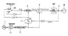
- FIG. 3 shows a block diagram of the commercial synchronous current control unit 4.
- the commercial synchronous current control unit 4 includes a buffer Z ⁇ 1 for outputting a value one sample before the detected three-phase current values I u , I v , and I w detected by the current sensor 2; Based on the phase information ⁇ s of the commercial power source 1 and the three-phase current detection values I u , I v , and I w of one sample before d based on the phase information ⁇ s of the commercial power source 1.
- the three-phase two-phase converter 7 for converting the shaft current detection value I d and the q axis current detection value I q , and the value one sample before the d axis current command value I d * and the q axis current command value I q * Based on the buffer Z- 1 to be output and the current control switching flag, the d-axis current detection value Id and the q-axis current detection value Iq are converted into the d-axis current command value Id * and the q-axis current during V / f control.
- a two-phase three-phase converter 8 for converting the d-axis voltage command value V d * and the q-axis voltage command value V q * into three-phase voltage command values V u * , V v * , V w * based on .
- the inverter INV is controlled based on the three-phase voltage command values V u * , V v * , V w * .
- the current control switching flag is turned on one cycle after the inverter output voltage from “synchronization completed”. The timing for turning on the current control switching flag is not limited to this.
- the command value of the current control unit 6 is a d-axis current detection value Id immediately before switching from V / f control (control to make the output voltage / output frequency ratio of the inverter INV constant) to current control (ACR control in FIG. 2). Since the q-axis current detection value Iq is used, the current control command value is continuously updated with the d-axis current detection value Id and the q-axis current detection value Iq until the current control switching flag is turned ON.
- V is an effective voltage value
- ⁇ is an output voltage phase of the inverter INV
- V is equal to an effective value of the output voltage of the commercial power source 1.
- I is the effective value of the current detection value.
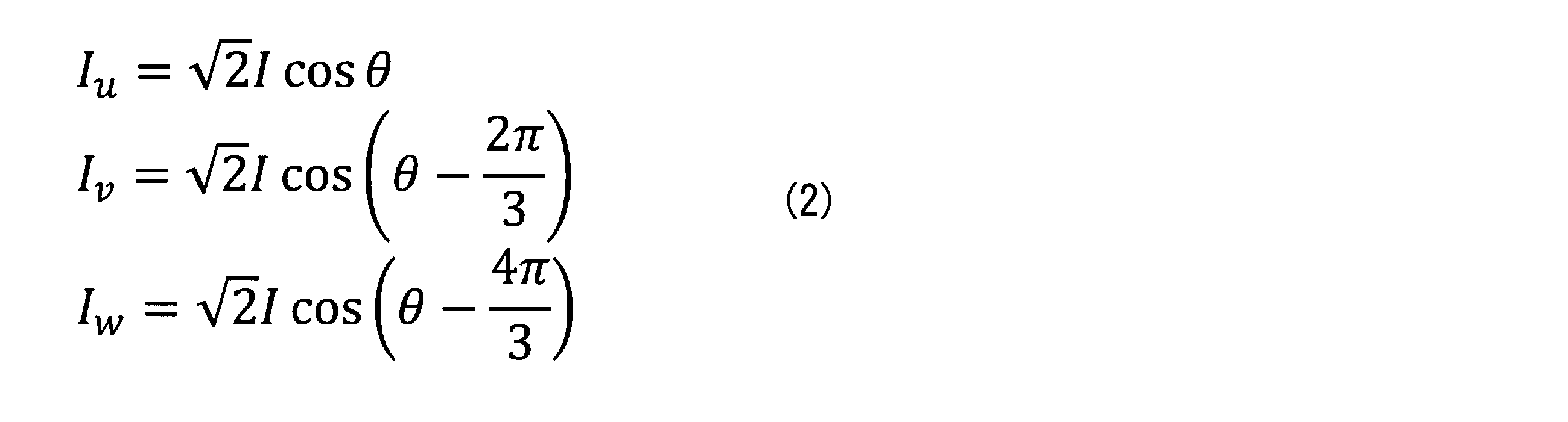
- the three-phase to two-phase conversion unit 7 uses the coordinate transformation formula of the following equation (3) to detect the d-axis current detection values I d and q from the three-phase current detection values I u , I v and I w. Coordinate conversion is performed on the shaft current detection value I q .
- the phase information used in the coordinate conversion uses the phase information ⁇ s of the commercial power source 1.
- ⁇ s is the phase information of the commercial power source 1.
- the d-axis current detection value I d and the q-axis current detection value I q are expressed by the following equation (4).
- the current control unit 6 performs proportional integral control (PI ) on the difference between the d-axis current command value I d * and the d-axis current detection value I d and the difference between the q-axis current command value I q * and the q-axis current detection value I q. Control), a d-axis voltage command value V d * and a q-axis voltage command value V q * are generated.
- the command value V q * is expressed by the following equation (6).
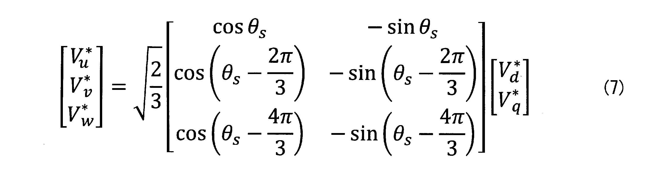
- the d-axis voltage command value V d * and the q-axis voltage command are calculated using the coordinate conversion formula of the following equation (7).
- the value V q * is converted into a three-phase voltage command value V u * , V v * , V w * .
- Control is performed so that the output voltage of the inverter INV becomes the three-phase voltage command values V u * , V v * , and V w * .
- the inverter INV in FIG. 3 performs ON / OFF control of the switching device inside the inverter using a comparison signal between the three-phase voltage command values V u * , V v * , V w * and a triangular wave signal, An output voltage of the inverter INV is generated.
- the synchronous control device for the power converter in the first embodiment it is possible to stably switch from the inverter INV drive to the commercial power source 1 drive. Further, compared with Patent Document 1, since current control is performed to detect the output current of the inverter INV and keep it at the current command value, the control accuracy is high, and the advantage of suppressing the cross current is high.
- the power converter when switching from the power converter drive to the commercial power source 1 drive, the power converter can make a stable transition without stopping a failure such as overcurrent or overvoltage. This improves the reliability of the motor drive system.
- a low-pass filter LPF is added to the commercial synchronous current control unit 4 of the first embodiment.
- FIG. 4 shows a block diagram of the commercial synchronous current control unit 4 in the second embodiment.
- a low-pass filter LPF is provided between the three-phase two-phase converter 7 and the changeover switch S4.
- the d-axis current detection value I d and the q-axis current detection value I q include the offset component due to the residual magnetic flux of the HCT that is the current sensor, the circuit error of the current sensor 2, and the primary component of the output frequency that is generated due to the detection gain deviation.
- a secondary component may be superimposed. Further, when noise is superimposed on the current sensor 2, it is also superimposed on the d-axis current detection value I d and the q-axis current detection value I q .
- the low-pass filter LPF has a function of suppressing and outputting high-frequency components of the input d-axis current detection value Id and q-axis current detection value Iq. Therefore, the above disturbance component that is a high frequency component is removed.
- the same effects as those of the first embodiment are obtained.
- the disturbance component is removed. It becomes possible to do.
- FIG. 5 shows a block diagram of the commercial synchronous current control unit 4 in the third embodiment.
- an attenuation processing unit 9 is provided between the changeover switch S ⁇ b> 4 and the current control unit 6. After the overlap between the output voltage of the inverter INV and the output voltage of the commercial power source 1, the on / off switch S2 for inverter operation shown in FIG. 1 is shut off.
- the on / off switch S2 is shut off, the current value on the commercial power source 1 side is temporarily Assuming that the current on the inverter INV side is almost the same as that of the motor when it is almost zero, the drive power supply is switched from the inverter INV side to the commercial power source 1 side, so the current on the commercial power source 1 side suddenly increases. The switching operation may become unstable. Therefore, when the on / off switch S2 is shut off, the current on the inverter INV side is gradually attenuated by the attenuation processing unit 9.
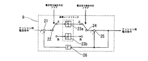
- FIG. 6 shows details of the attenuation processing unit 9.
- the subtracter 21 subtracts the output of one sample before the subtracter 25 described later from the output of the changeover switch S4.
- the switch 22 determines the polarities of the d-axis current command value I d * and the q-axis current command value I q * based on the current command polarity determination flag, and sets the switch 22 to the positive side or the negative side based on the determination result. Switch.
- the polarities of the d-axis current command value I d * and the q-axis current command value I q * are positive, the d-axis current command value I d * and the q-axis current are attenuated from positive to zero by the attenuation rate limiter 23a.
- the command value I q * is attenuated. Further, when the polarities of the d-axis current command value I d * and the q-axis current command value I q * are negative, the d-axis current command value I d * , at the rate of attenuation from negative to zero by the attenuation rate limiter 23b. The q-axis current command value I q * is attenuated.
- the switch 24 operates in the same manner as the switch 22.
- the subtracter 25 subtracts the output of the switch 24 from the output of the subtracter 25.
- the buffer 26 outputs the value one sample before the subtracter 25.
- the current command polarity determination flag is set according to the polarity of the current command before cushion in FIG. If the polarity of the pre-cushion current command is positive, the current command polarity determination flag is positive, and the switches 22 and 24 are on the positive side. If the polarity of the pre-cushion current command is negative, the current command polarity determination flag is negative, and the switches 22 and 24 are on the negative side.
- the attenuation processing unit 9 is configured as shown in FIG. 6 for each of the d-axis current command value I d * and the q-axis current command value I q * .
- FIG. 7 shows the flow of commercial synchronization control in the third embodiment. It should be noted that rate attenuation is not performed in a period before “INV current reduction start” in FIG. 7 which is a predetermined time after switching to current control. Further, the open / close switch S1 for the commercial power source 1 is turned on during the period from “control switching” to “INV current reduction start” in FIG.
- the same operational effects as those in the first and second embodiments are obtained.
- the current on the inverter INV side is almost zero when the opening / closing switch S2 for the inverter INV is cut off, it is possible to suppress an unstable phenomenon that occurs when switching from the inverter INV drive to the commercial power source 1 drive. .
- the d-axis current command value I d * and the q-axis current command value I q * are simultaneously attenuated.
- the d-axis current is reduced to 0 after the q-axis current is attenuated to 0. It attenuates.
- the d-axis current I d is a current that controls the magnetic flux. Since the motor M cannot generate torque and cannot rotate unless magnetic flux is generated, the switching operation is more stable when attenuated by the method of the fourth embodiment.
- FIG. 8 shows details of the attenuation processing unit 9 of the fourth embodiment.
- a current command 0 determination unit 41 for determining whether or not the q-axis current command value I q * becomes 0 is provided on the output side of the attenuation processing unit 9, and a q-axis current command 0 flag is output.
- the current command 0 determination unit 41 outputs the value input from the subtractor 25 as it is as a post-cushion q-axis current command.
- the current command polarity determination flag in FIG. 8 is set according to the polarity of the pre-cushion q-axis current command in FIG.
- switches 42 and 43 that are turned ON when the q-axis current command 0 flag is input from the current command 0 determination unit 41 are provided on the input side and output side of the attenuation processing unit 9.
- the q-axis current command value I q * 0
- the current command 0 determination unit 41 in the lower part of FIG. 8 sets the q-axis current command 0 flag, and switches 42 and 43 in the upper part of FIG. Processing unit 9 side).
- the attenuation process can be performed even in a configuration in which the d-axis current is attenuated to 0 and then the q-axis current is attenuated to 0.
- the same operational effects as those of the first to third embodiments are obtained. Further, the switching operation is more stable when switching from the inverter INV drive to the commercial power source 1 drive as compared with the third embodiment.
- FIG. 9 shows a block diagram of the commercial synchronous current control unit 4 in the fifth embodiment.
- the output voltage phase of the inverter INV is driven by the output voltage phase of the commercial power supply 1 after switching to the current control, but is driven by the phase ⁇ obtained from the output frequency calculation of the inverter INV during the V / f control.
- the output frequency calculation unit 10 that calculates the output frequency of the inverter INV
- the phase calculation processing unit 11 that calculates the output voltage phase ⁇ of the inverter INV, the output voltage phase ⁇ 1 of the commercial power supply 1, and the output voltage phase ⁇ of the inverter INV.
- a change rate limit processing unit 12 that holds the shift amount at the time of switching and sets a change rate limit to gradually set the shift amount to 0.
- the rate-of-change limiting processing unit 12 calculates a difference ( ⁇ 1) between the output voltage phase ⁇ 1 of the commercial power source 1 and the output voltage phase ⁇ of the inverter INV output by the phase calculation processing unit 11 of FIG.
- a switch that outputs the difference between the output voltage phase of the commercial power supply 1 and the output voltage phase ⁇ of the inverter INV during the period when the synchronization completion flag is OFF, and outputs the output one sample before of the switch 56 described later when the synchronization completion flag is ON.
- the difference between the phase ⁇ 1 of the immediately preceding commercial power supply 1 and the phase ⁇ of the phase calculation processing unit 11 is determined by the attenuation rate limiters 54a and 54b It will be attenuated by.
- the polarity of whether the phase difference ( ⁇ 1) is positive or negative is determined. If the phase difference is positive, the phase error polarity determination flag is set to positive, and the attenuation rate limiter 54a sets the phase difference from positive to zero. Attenuate.
- phase difference is negative, the phase error polarity determination flag is set to negative, the phase difference is attenuated by the attenuation rate limiter 54b so that the phase difference changes from negative to zero, and the absolute value calculation processing unit 55 performs absolute value calculation. . Either positive or negative is limited when it becomes 0, and the attenuation rate limiters 54a and 54b output 0. The value obtained by subtracting the output of this process (the output of the switch 56) from the phase ⁇ 1 of the commercial power source 1 is used as the phase information ⁇ s used in the three-phase two-phase converter 7 and the two-phase three-phase converter 8 in FIG.
- the same operational effects as those of the first to fourth embodiments are obtained.
- the change rate limiting processing unit 12 it is possible to suppress a failure stop without causing a sudden change in current when the overlap driving is performed between the inverter INV driving and the commercial power source 1 driving, and stable operation is performed. Is possible.
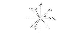
- FIG. 11 shows the relationship between the three-phase AC voltage vector, the ⁇ - ⁇ coordinate system, and the dq coordinate system.
- the ⁇ - ⁇ coordinate system is a coordinate system after three-phase to two-phase transformation, and is called a fixed coordinate system.
- the dq coordinate system is a coordinate system that rotates the ⁇ - ⁇ coordinate system at a certain phase.
- the coordinates that rotate in synchronization with the primary frequency of the motor M are referred to as a rotational coordinate system.
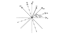
- a coordinate system that rotates in synchronization with the primary frequency of the motor M is defined as a dm-qm coordinate system
- a coordinate system that rotates in synchronization with the voltage phase of the commercial power source 1 is defined as a ds-qs coordinate system. The figure is shown.
- the phase of the primary frequency of the motor M is ⁇ m, and the phase information of the commercial power source 1 is ⁇ s.
- the voltage vector V1 is defined as shown in FIG.
- the voltage vector V1 is distributed to the dm-qm coordinate system and the ds-qs coordinate system.
- the d-axis voltage in the dm-qm coordinate system is Vdm
- the q-axis voltage is Vqm
- the d-axis voltage in the ds-qs coordinate system is Vds
- the q-axis voltage is Vqs.
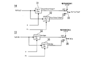
- FIG. 13 shows a block diagram of the commercial synchronous current control unit 4 of the sixth embodiment.
- coordinate axis selectors 13 and 14 are provided instead of the three-phase two-phase converter 7 and the two-phase three-phase converter 8 of the fifth embodiment.
- the above processing is performed by the coordinate axis selectors 13 and 14.
- FIG. 14 is a detailed block diagram of the coordinate axis selectors 13 and 14. As shown in FIG. 14, the coordinate axis selection unit 14 includes two-phase three-phase conversion units 31 and 32, and the coordinate axis selection unit 13 includes three-phase two-phase conversion units 34 and 35.
- the two-phase three-phase conversion unit 32 and the three-phase two-phase conversion unit 35 perform coordinate conversion using the phase information ⁇ s of the commercial power supply 1, and the two-phase three-phase conversion unit 31 and the three-phase two-phase conversion unit 34 output the inverter INV. Coordinate conversion is performed with the voltage phase ⁇ .
- the current control switching flag is set at the timing of “control switching” in FIG. 2 or FIG.
- the changeover switches 33 and 36 in FIG. 14 are in the OFF side, and the two-phase three-phase conversion unit 31 and the three-phase two-phase conversion unit 34 output the output frequency command in the inverter INV.
- the coordinate conversion is performed with the output voltage phase ⁇ from.
- the selector switches 33 and 36 in FIG. 14 are turned on, and the phase information ⁇ s of the commercial power source 1 is obtained in the two-phase three-phase converter 32 and the three-phase two-phase converter 35. The coordinates will be converted with.
- the same operational effects as those of the first to fifth embodiments are obtained. Further, it is possible to switch to the output voltage phase of the commercial power supply 1 while maintaining the magnitude of the vector of the motor M and the primary voltage.
- FIG. 15 shows the commercial synchronous current control unit 4 of the seventh embodiment.
- the current control may be performed with the three-phase current without converting the coordinates.
- the two-phase three-phase conversion unit 8 converts the d-axis current command value I d * and the q-axis current command value I q * into a three-phase current command value.
- I u * , I v * , and I w * are generated.
- the current control unit 6 determines the three-phase voltage command value V based on the deviation between the three-phase current command values I u * , I v * , I w * and the three-phase current detection values I u , I v , I w. u *, V v *, to calculate the V w *.
- the same operational effects as those of the first to sixth embodiments are obtained. Further, it is not necessary to perform coordinate conversion during current control, and the configuration of the current control system is simplified.
- Embodiment 8 A voltage drop occurs in the output voltage of the inverter INV due to the AC reactor L connected to the output side of the inverter INV.
- the voltage drop due to the AC reactor L becomes a potential difference and a phase difference between the output voltage of the inverter INV and the commercial power supply voltage, and a cross current is generated.
- the voltage drop by the AC reactor L is compensated.
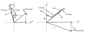
- FIG. 17 shows a vector diagram of the output voltage of the inverter INV.
- the left side of FIG. 17 shows the driving load, and the right side of FIG. 17 shows the state of the regenerative load.
- an induction motor (motor) is shown as an example.
- I1 primary current
- I d d-axis current detection value
- I q q-axis current detection value
- L1 inductance of AC reactor L
- Ls motor leakage reactance
- R1 primary resistance of motor
- V1 motor terminal output voltage
- E2 motor induced voltage
- Vac1 voltage drop due to AC reactor L.
- V1 + Vac1 is the output voltage of the inverter INV
- V1 is the motor terminal voltage.
- the output voltage V1 + Vac1 of the inverter INV is the motor terminal voltage V1.
- the commercial power source 1 is connected to the motor M via an electromagnetic contactor, a difference occurs and cross current is generated only by matching the voltage of the commercial power source 1 with the magnitude and phase of the output voltage V1 + Vac1 of the inverter INV. If the voltage drop Vac1 of the AC reactor L is compensated, the cross current can be suppressed.
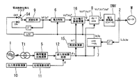
- FIG. 18 is a block diagram showing the commercial synchronous current control unit 4 in the eighth embodiment.
- the commercial synchronous current control unit 4 according to the eighth embodiment is obtained by adding a frequency calculation unit 15 and an output voltage error compensation unit 16 to the commercial synchronous current control unit 4 according to the seventh embodiment.
- the output voltage error compensation unit 16 compensates the voltage drop Vac1 of the AC reactor L.
- the frequency component used in the output voltage error compensation unit 16 is obtained by differentiating the phase information ⁇ s output from the change rate restriction processing unit 12. Further, the frequency calculation unit 15 multiplies the phase information ⁇ s by 2 ⁇ to obtain the angular frequency component ⁇ 1.
- the output voltage error compensation unit 16 is provided on each of the d axis and the q axis.
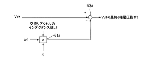
- FIG. 19 shows the output voltage error compensator 16 for the d axis
- FIG. 20 shows the details of the output voltage error compensator 16 for the q axis.
- the d-axis output voltage error compensation unit 16 multiplies the angular frequency component ⁇ 1, the inductance value L1 of the AC reactor L, and the q-axis current detection value Iq in a multiplier 61a.
- the subtractor 62a subtracts the output ⁇ 1 ⁇ L1 ⁇ I q of the multiplier 61b from the d-axis voltage command value Vd * to obtain the final d-axis voltage command value Vd1 * .
- the q-axis output voltage error compensation unit 16 multiplies the angular frequency component ⁇ 1, the inductance value L1 of the AC reactor L, and the d-axis current detection value Id in the multiplier 61b. It adds the output ⁇ 1 ⁇ L1 ⁇ I d of q-axis voltage command value Vq * and the multiplier 61b in an adder 62b, and a final q-axis voltage command value Vq1 *.
- the current control for detecting the output current of the inverter INV and maintaining the command value is performed, so that the control accuracy is high, and therefore the switching operation is performed.
- the effect of suppressing the cross current inside is high.
- the overcurrent suppressing effect is further improved, and the reliability of the motor drive system is further improved.
- the output voltage error compensator 16 is provided with a dead band.
- the q-axis current value is 0, so that the polarity may be reversed if noise is superimposed on the current detection value. If the polarity is reversed, there is a possibility that it is shifted from the component to be compensated originally. Therefore, a dead band is provided so that a component generated by the q-axis current is not compensated when there is no load or light load (that is, when the current detection values Iu, Iv, and Iw in FIG. 18 are equal to or less than a predetermined value). .
- FIG. 21 shows details of the output voltage error compensator 16 when the dead band 63 is provided.
- the dead band 63 receives the q-axis current command value I q and outputs the output to the multiplier 61a.
- the output of the dead band 63 outputs 0 when the absolute value of Iq is less than or equal to a predetermined value, and outputs Iq when the absolute value of Iq exceeds the predetermined value.
- Other configurations are the same as those of the eighth embodiment.
- the ninth embodiment has the same effects as the eighth embodiment. Further, in the case where the current detection values Iu, Iv, and Iw are equal to or less than a predetermined value, even if noise is superimposed on the current detection values Iu, Iv, and Iw, it is possible to suppress the polarity reversal and deviation from the originally compensated noise. .
- the voltage command values Vd * and Vq * , the angular frequency component ⁇ 1, and the current detection values Id and Iq are used, but the current command value Id is used instead of the current detection values Id and Iq.
- the voltage drop Vac1 of the AC reactor L may be compensated using the information of * and Iq * .
- FIG. 22 shows a block diagram of the commercial synchronous current control unit 4 in the tenth embodiment. Since current control is performed, the current detection values Id, Iq and the current command values Id * , Iq * may be regarded as matching. The current command values Id * and Iq * are regarded as equivalent to the current detection values because the current detection values Id and Iq immediately before switching from the V / f control to the current control in FIG. 2 are used.
- the tenth embodiment has the same effects as the eighth and ninth embodiments. Further, by using the current command values Id * and Iq * , it is possible to remove disturbance components such as noise that may be included in the current detection values Id and Iq.
- FIG. 23 shows a block diagram of the output voltage error compensator 16 in the eleventh embodiment.
- the voltage drop compensation of the AC reactor L is given as a fixed value.
- the output voltage error compensation unit 16 in the eleventh embodiment includes a multiplier 64, a ⁇ comp operation unit 65, multipliers 66a and 66b, a subtractor 67a, and an adder 67b. .
- the multiplier 64 calculates the voltage drop compensation value Vcomp by multiplying the inductance value L1 of the AC reactor L, the angular frequency component ⁇ 1, and the current value I of the load operation state during commercial synchronization.
- the ⁇ comp calculator 65 calculates ⁇ comp based on the d-axis current command value Id * and the q-axis current command value Iq * .
- the multiplier 66a multiplies the voltage drop compensation value Vcomp and sin ( ⁇ comp) to calculate the d-axis voltage drop compensation component Vd_comp.
- the multiplier 66b multiplies the voltage drop compensation value Vcomp and cos ( ⁇ comp) to calculate a q-axis voltage drop compensation component Vq_comp.
- the subtractor 67a subtracts the d-axis voltage drop compensation component Vd_comp from the d-axis voltage command value Vd * and outputs it as the final d-axis voltage command value Vd1 * .
- the adder 67b adds the q-axis voltage command value Vq * and the q-axis voltage drop compensation component Vq_comp and outputs the result as the final q-axis voltage command value Vq1 * .
- the voltage drop compensation value can be calculated by the following equation (9). If this method is used, the voltage drop Vac1 of the AC reactor L can be compensated without the current sensor 2 or the frequency calculation unit 15 of FIG. Let the voltage drop compensation value be Vcomp.
- FIG. 24 shows a vector diagram of only the dq-axis current command values I d * and I q * and the voltage drop Vac1 of the AC reactor L. Since there is no difference in the way of thinking between driving and regeneration, only the driving load is shown.
- the conversion to the dq axis voltage compensation component can be performed by calculating the following equations (11) and (12) using ⁇ comp obtained by the above equation (10).
- the d-axis voltage compensation component is Vd_comp
- the q-axis voltage compensation component is Vq_comp.
- the angular frequency component ⁇ 1, the d-axis current command value Id * , and the q-axis current command value Iq * are both fixed values, and the d-axis voltage drop compensation component Vd_comp and the q-axis voltage drop compensation component Vq_comp are obtained from the above equation. Asked.
- a method may be applied in which only one is a fixed value and the other is obtained from the detected value shown in FIG.
- the same operational effects as those of the eighth to tenth embodiments are obtained. Further, the voltage drop Vac1 of the AC reactor L can be compensated without the current sensor 2 and the frequency calculation unit 18.
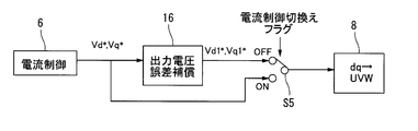
- the changeover switch S5 is provided between the output voltage error compensation unit 16 and the two-phase / three-phase conversion unit 8.
- the selector switch S5 inputs the dq axis voltage command values Vd * and Vq * and the final dq axis voltage command values Vd1 * and Vq1 * .
- it is connected to the ON side, and dq-axis voltage command values Vd * and Vq * are output to the two-phase / three-phase converter 8.
- the inverter INV outputs a voltage including the voltage drop Vac1 of the AC reactor L.
- the information on the current detection value includes the voltage drop Vac1 of the AC reactor L, there is no need for output voltage error compensation.
Landscapes
- Engineering & Computer Science (AREA)
- Power Engineering (AREA)
- Control Of Ac Motors In General (AREA)
- Inverter Devices (AREA)
- Motor And Converter Starters (AREA)
Abstract
Description
本実施形態1における電力変換器の同期制御装置の概略構成を図1に示す。商用電源1は三相交流電源である。商用電源1とモータMとの間には商用電源1駆動用の開閉スイッチS1が接続されている。また、商用電源1用の開閉スイッチS1と並列に、入力用トランスT2、インバータINV、交流リアクトルL、インバータINV用の開閉スイッチS2の直列回路が接続されている。また、インバータINVの出力側には、インバータINVの三相電流検出値Iu,Iv,Iwを検出する電流センサ2が設けられている。開閉スイッチS1,S2の入り切りを行うことにより商用電源1駆動とインバータINV駆動の切り換えを行う。




本実施形態2は、実施形態1の商用同期電流制御部4にローパスフィルタLPFを加えたものである。
図5に本実施形態3における商用同期電流制御部4のブロック図を示す。図5に示すように、本実施形態3では、切換スイッチS4と電流制御部6との間に減衰処理部9を設けている。インバータINVの出力電圧と商用電源1の出力電圧とのオーバーラップ後に、図1に示すインバータ運転用の開閉スイッチS2を遮断するが、仮にこの開閉スイッチS2の遮断時に商用電源1側の電流値がほぼ0でインバータINV側の電流がモータの電流とほぼ一致しているとすると、駆動電力の供給がインバータINV側→商用電源1側に切り換わるため瞬間的に商用電源1側の電流が急増し、切換動作が不安定になる可能性がある。そのため、開閉スイッチS2を遮断する際には、減衰処理部9により、インバータINV側の電流を徐々に減衰させる。
実施形態3ではd軸電流指令値Id *とq軸電流指令値Iq *を同時に減衰させたが、本実施形態4は、q軸電流を0に減衰してからd軸電流を0に減衰するものである。
また、d軸電流を0に減衰してからq軸電流を0に減衰するような構成にしても、減衰処理は行える。
図9に本実施形態5における商用同期電流制御部4のブロック図を示す。
実施形態1と実施形態5ではインバータINVの出力周波数位相の座標系から商用電源1の出力電圧位相の座標系に移行する際には位相のみに着目していたが、本実施形態6では、位相と電圧の大きさを考慮して座標系を移行する。図11に三相交流の電圧ベクトルとα-β座標系,d-q座標系の関係を示す。
本実施形態7の商用同期電流制御部4を図15に示す。電流制御を座標変換せずに三相電流のまま行ってもよい。この場合は、図15に示すように、d軸電流指令値Id *,q軸電流指令値Iq *を二相三相変換部8により二相三相変換して、三相電流指令値Iu *,Iv *,Iw *を生成する。そして、電流制御部6において、三相電流指令値Iu *,Iv *,Iw *と三相電流検出値Iu,Iv,Iwとの偏差に基づいて三相電圧指令値Vu *,Vv *,Vw *を算出する。
インバータINVの出力電圧は、インバータINVの出力側に接続されている交流リアクトルLにより電圧降下が発生する。この交流リアクトルLによる電圧降下がインバータINVの出力電圧と商用電源電圧の電位差と位相差になり横流が発生する。本実施形態8では、この横流を抑制するために交流リアクトルLによる電圧降下を補償する。
本実施形態9は、出力電圧誤差補償部16にデッドバンドを設けたものである。無負荷時にはq軸電流値が0となるので電流検出値にノイズが重畳されると極性が反転する可能性がある。極性が反転すると本来補償したい成分とずれる可能性がある。よって、デッドバンドを設け、無負荷時もしくは軽負荷時(すなわち、図18の電流検出値Iu,Iv,Iwが所定値以下の場合)にはq軸電流によって発生する成分は補償しないようにする。
実施形態8の出力電圧誤差補償部16では電圧指令値Vd*,Vq*,角周波数成分ω1,電流検出値Id,Iqを用いているが、電流検出値Id,Iqの代わりに電流指令値Id*,Iq*の情報を用いて交流リアクトルLの電圧降下分Vac1を補償してもよい。
図23に本実施形態11における出力電圧誤差補償部16のブロック図を示す。本実施形態11は、交流リアクトルLの電圧降下補償を固定値で与えるものである。




本実施形態12は、同期完了前のV/f制御中に出力電圧誤差補償を行うものである。本実施形態12を適用した場合、図18,図22の電流制御部6,出力電圧誤差補償部16,二相三相変換部8間の構成は図25となる。
Claims (13)
- 商用電源とモータとの間に接続された第1の開閉スイッチと、
前記第1の開閉スイッチに対して並列に接続された電力変換器と交流リアクトルと第2の開閉スイッチとを有する直列回路と、
モータの始動時から商用電源の出力電圧と電力変換器の出力電圧が同期するまで電力変換器を制御する同期制御部と、
商用電源の出力電圧と電力変換器の出力電圧が同期した後に、電力変換器を制御する商用同期電流制御部と、を備え、
前記同期制御部による電力変換器の制御から前記商用同期電流制御部による電力変換器の制御へ切り換える電力変換器の同期制御装置であって、
前記同期制御部は、前記第1の開閉スイッチを「開」、前記第2の開閉スイッチを「閉」として、電力変換器をV/f制御で運転し、
前記商用同期電流制御部は、
前記同期制御部による電力変換器の制御からの切り換え直後は、前記第1の開閉スイッチを「開」、前記第2の開閉スイッチを「閉」として、電力変換器をV/f制御で運転し、その後、電力変換器を電力変換器の出力の電流検出値に基づいた電流制御に変更し、
その後、第1の開閉スイッチを「閉」にして、電力変換器と商用電源の両方からモータに給電し、その後、第2の開閉スイッチを「開」として、商用電源からモータへ給電する電力変換器の同期制御装置。 - 前記商用同期電流制御部は、
商用電源の位相情報に基づいて、電力変換器出力の三相電流検出値をd軸電流検出値,q軸電流検出値に変換する三相二相変換部と、
V/f制御時はd軸電流検出値とq軸電流検出値をd軸電流指令値とq軸電流指令値として出力し、電流制御時は1サンプル前のd軸電流指令値とq軸電流指令値をd軸電流指令値とq軸電流指令値として出力する切換スイッチと、
d軸電流検出値とd軸電流指令値との偏差、q軸電流検出値とq軸電流指令値との偏差に基づいて、d軸電圧指令値とq軸電圧指令値とを出力する電流制御部と、
商用電源の位相情報に基づいて、d軸電圧指令値とq軸電圧指令値を三相電圧指令値に変換する二相三相変換部と、
を備えた請求項1記載の電力変換器の同期制御装置。 - 前記商用同期電流制御部は、
商用電源の位相情報に基づいて、電力変換器出力の三相電流検出値をd軸電流検出値とq軸電流検出値に変換する三相二相変換部と、
V/f制御時はd軸電流検出値とq軸電流検出値をd軸電流指令値とq軸電流指令値として出力し、電流制御時は1サンプル前のd軸電流指令値とq軸電流指令値をd軸電流指令値とq軸電流指令値として出力する切換スイッチと、
商用電源の位相情報に基づいて、d軸電流指令値とq軸電流指令値を三相電流指令値に変換する二相三相変換部と、
三相電流検出値と三相電流指令値との偏差に基づいて、三相電圧指令値を出力する電流制御部と、
を備えた請求項1記載の電力変換器の同期制御装置。 - 前記商用同期電流制御部は、
商用電源の位相情報に基づいて、電力変換器出力の三相電流検出値をd軸電流検出値,q軸電流検出値に変換する三相二相変換部と、
V/f制御時はd軸電流検出値とq軸電流検出値をd軸電流指令値とq軸電流指令値として出力し、電流制御時は1サンプル前のd軸電流指令値とq軸電流指令値をd軸電流指令値とq軸電流指令値として出力する切換スイッチと、
d軸電流検出値とd軸電流指令値との偏差、q軸電流検出値とq軸電流指令値との偏差に基づいて、d軸電圧指令値とq軸電圧指令値とを出力する電流制御部と、
前記d軸電圧指令値から、交流リアクトルのインダクタンス値と角周波数成分とq軸電流検出値とを乗算した値を減算して最終d軸電圧指令値として出力し、前記q軸電圧指令値に、交流リアクトルのインダクタンス値と角周波数成分とd軸電流検出値とを乗算した値を加算して最終q軸電圧指令値として出力する出力電圧誤差補償部と、
商用電源の位相情報に基づいて、最終d軸電圧指令値と最終q軸電圧指令値を三相電圧指令値に変換する二相三相変換部と、
を備えた請求項1記載の電力変換器の同期制御装置。 - 前記商用同期電流制御部は、
商用電源の位相情報に基づいて、電力変換器出力の三相電流検出値をd軸電流検出値,q軸電流検出値に変換する三相二相変換部と、
V/f制御時はd軸電流検出値とq軸電流検出値をd軸電流指令値とq軸電流指令値として出力し、電流制御時は1サンプル前のd軸電流指令値とq軸電流指令値をd軸電流指令値とq軸電流指令値として出力する切換スイッチと、
d軸電流検出値とd軸電流指令値との偏差、q軸電流検出値とq軸電流指令値との偏差に基づいて、d軸電圧指令値とq軸電圧指令値とを出力する電流制御部と、
前記d軸電圧指令値から、交流リアクトルのインダクタンス値と角周波数成分とq軸電流指令値とを乗算した値を減算して最終d軸電圧指令値として出力し、前記q軸電圧指令値に、交流リアクトルのインダクタンス値と角周波数成分とd軸電流指令値とを乗算した値を加算して最終q軸電圧指令値として出力する出力電圧誤差補償部と、
商用電源の位相情報に基づいて、最終d軸電圧指令値と最終q軸電圧指令値を三相電圧指令値に変換する二相三相変換部と、
を備えた請求項1記載の電力変換器の同期制御装置。 - 前記商用同期電流制御部は、
商用電源の位相情報に基づいて、電力変換器出力の三相電流検出値をd軸電流検出値,q軸電流検出値に変換する三相二相変換部と、
V/f制御時はd軸電流検出値とq軸電流検出値をd軸電流指令値とq軸電流指令値として出力し、電流制御時は1サンプル前のd軸電流指令値とq軸電流指令値をd軸電流指令値とq軸電流指令値として出力する切換スイッチと、
d軸電流検出値とd軸電流指令値との偏差、q軸電流検出値とq軸電流指令値との偏差に基づいて、d軸電圧指令値とq軸電圧指令値とを出力する電流制御部と、
交流リアクトルのインダクタンス値と角周波数成分と商用同期時の負荷運転状況の電流値とを乗算して電圧降下補償値を演算し、d軸電流指令値とq軸電流指令値に基づいてθcomp=tan-1(d軸電流指令値/q軸電流指令値)を演算し、前記電圧降下補償値とsin(θcomp)とを乗算して、d軸電圧降下補償成分を演算し、前記電圧降下補償値とcos(θcomp)とを乗算して、q軸電圧降下補償成分を演算し、d軸電圧指令値からd軸電圧降下補償成分を減算して最終q軸電圧指令値として出力し、q軸電圧指令値とq軸電圧降下補償成分とを加算し、最終d軸電圧指令値として出力する出力電圧誤差補償部と、
商用電源の位相情報に基づいて、最終d軸電圧指令値と最終q軸電圧指令値を三相電圧指令値に変換する二相三相変換部と、
を備え、前記商用同期時の負荷運転状況の電流値と角周波数成分のうち少なくとも何れか一方を固定値とする請求項1記載の電力変換器の同期制御装置。 - 前記出力電圧誤差補償部は、
前記q軸電流検出値の絶対値または前記q軸電流指令値の絶対値が所定値以下の場合0とする請求項4~6記載の電力変換器の同期制御装置。 - d軸電圧指令値とq軸電圧指令値と最終d軸電圧指令値と最終q軸電圧指令値とを入力し、V/f制御時最終d軸電圧指令値と最終q軸電圧指令値とを二相三相変換部に出力し、電流制御時d軸電圧指令値とq軸電圧指令値とを二相三相変換部に出力する切替スイッチを有する請求項4~7のうち何れか1項に記載の電力変換器の同期制御装置。
- 前記商用同期電流制御部は、
前記d軸電流検出値と前記q軸電流検出値の高周波成分を除去し、前記切換スイッチに出力するローパスフィルタを備えた請求項2~6のうち何れか1項に記載の電力変換器の同期制御装置。 - 前記商用同期電流制御部は、
電流制御に切り換わってから所定時間後、d軸電流指令値とq軸電流指令値を減衰する請求項2~7のうち何れかに記載の電力変換器の同期制御装置。 - 前記商用同期電流制御部は、
q軸電流指令値を0に減衰させてから、d軸電流指令値を0に減衰させる請求項10記載の電力変換器の同期制御装置。 - 前記商用同期電流制御部は、
電力変換器の出力電圧位相と商用電源の出力電圧位相との間に誤差がある場合、前記商用電源の位相情報を電力変換器の出力電圧位相から商用電源の出力電圧位相に徐々に変化させる請求項2~9のうち何れかに1項に記載の電力変換器の同期制御装置。 - 前記二相三相変換部は、
V/f制御時に、電力変換器の出力電圧位相に基づいてd軸電圧指令値とq軸電圧指令値を三相電圧指令値に変換し、
電流制御時に、商用電源の位相情報に基づいて、d軸電圧指令値とq軸電圧指令値を三相電圧指令値に変換し、
前記三相二相変換部は、
V/f制御時に、電力変換器の出力電圧位相に基づいて、三相電流検出値をd軸電流検出値とq軸電流検出値に変換し、
電流制御時に、商用電源の位相情報に基づいて、三相電流検出値をd軸電流検出値とq軸電流検出値に変換する請求項2~12のうち何れか1項に記載の電力変換器の同期制御装置。
Priority Applications (3)
| Application Number | Priority Date | Filing Date | Title |
|---|---|---|---|
| CN201680014462.6A CN107408901B (zh) | 2015-03-10 | 2016-02-19 | 用于电力转换器的同步控制设备 |
| JP2017504943A JP6288368B2 (ja) | 2015-03-10 | 2016-02-19 | 電力変換器の同期制御装置 |
| RU2017133495A RU2667477C1 (ru) | 2015-03-10 | 2016-02-19 | Устройство для управления синхронизацией преобразователя мощности |
Applications Claiming Priority (2)
| Application Number | Priority Date | Filing Date | Title |
|---|---|---|---|
| JP2015-046997 | 2015-03-10 | ||
| JP2015046997 | 2015-03-10 |
Publications (1)
| Publication Number | Publication Date |
|---|---|
| WO2016143481A1 true WO2016143481A1 (ja) | 2016-09-15 |
Family
ID=56880431
Family Applications (1)
| Application Number | Title | Priority Date | Filing Date |
|---|---|---|---|
| PCT/JP2016/054794 Ceased WO2016143481A1 (ja) | 2015-03-10 | 2016-02-19 | 電力変換器の同期制御装置 |
Country Status (4)
| Country | Link |
|---|---|
| JP (1) | JP6288368B2 (ja) |
| CN (1) | CN107408901B (ja) |
| RU (1) | RU2667477C1 (ja) |
| WO (1) | WO2016143481A1 (ja) |
Cited By (2)
| Publication number | Priority date | Publication date | Assignee | Title |
|---|---|---|---|---|
| WO2019187815A1 (ja) * | 2018-03-29 | 2019-10-03 | オムロン株式会社 | モータ制御装置 |
| WO2020170642A1 (ja) * | 2019-02-20 | 2020-08-27 | 日本電産株式会社 | 位置推定装置 |
Citations (3)
| Publication number | Priority date | Publication date | Assignee | Title |
|---|---|---|---|---|
| JPH089682A (ja) * | 1994-06-21 | 1996-01-12 | Toshiba Corp | 誘導機制御装置 |
| JP3678781B2 (ja) * | 1994-12-21 | 2005-08-03 | 東芝プラントシステム株式会社 | 交流電動機の制御装置 |
| JP2006149136A (ja) * | 2004-11-24 | 2006-06-08 | Fuji Electric Systems Co Ltd | 駆動電源切替えの同期制御装置 |
Family Cites Families (9)
| Publication number | Priority date | Publication date | Assignee | Title |
|---|---|---|---|---|
| DE3133311C2 (de) * | 1981-08-22 | 1985-03-07 | Licentia Patent-Verwaltungs-Gmbh, 6000 Frankfurt | Verfahren zur Synchronisation eines Stromrichter-Synchronmotors mit einem speisenden Netz |
| US5212438A (en) * | 1987-09-24 | 1993-05-18 | Kabushiki Kaisha Toshiba | Induction motor control system |
| RU2132110C1 (ru) * | 1998-03-25 | 1999-06-20 | Мищенко Владислав Алексеевич | Способ оптимального векторного управления асинхронным электродвигателем и электропривод для осуществления этого способа (варианты) |
| RU2141719C1 (ru) * | 1998-03-25 | 1999-11-20 | Мищенко Владислав Алексеевич | Способ векторного управления синхронным электродвигателем с постоянными магнитами на роторе и электропривод для осуществления этого способа |
| JP4702094B2 (ja) * | 2006-02-24 | 2011-06-15 | 株式会社明電舎 | インバータの同期制御装置 |
| CN201199677Y (zh) * | 2008-01-18 | 2009-02-25 | 郑欣棣 | 电机电源控制装置 |
| EP2214303B1 (en) * | 2009-01-28 | 2011-11-30 | ABB Oy | Synchronizing an inverter with an alternating voltage source |
| WO2012098875A1 (ja) * | 2011-01-18 | 2012-07-26 | ダイキン工業株式会社 | 電力変換装置 |
| CN102790562A (zh) * | 2012-08-10 | 2012-11-21 | 上海新时达电气股份有限公司 | 一种将电机在变频电源与工频电源间平滑切换的方法 |
-
2016
- 2016-02-19 WO PCT/JP2016/054794 patent/WO2016143481A1/ja not_active Ceased
- 2016-02-19 JP JP2017504943A patent/JP6288368B2/ja active Active
- 2016-02-19 CN CN201680014462.6A patent/CN107408901B/zh active Active
- 2016-02-19 RU RU2017133495A patent/RU2667477C1/ru active
Patent Citations (3)
| Publication number | Priority date | Publication date | Assignee | Title |
|---|---|---|---|---|
| JPH089682A (ja) * | 1994-06-21 | 1996-01-12 | Toshiba Corp | 誘導機制御装置 |
| JP3678781B2 (ja) * | 1994-12-21 | 2005-08-03 | 東芝プラントシステム株式会社 | 交流電動機の制御装置 |
| JP2006149136A (ja) * | 2004-11-24 | 2006-06-08 | Fuji Electric Systems Co Ltd | 駆動電源切替えの同期制御装置 |
Cited By (5)
| Publication number | Priority date | Publication date | Assignee | Title |
|---|---|---|---|---|
| WO2019187815A1 (ja) * | 2018-03-29 | 2019-10-03 | オムロン株式会社 | モータ制御装置 |
| JP2019176649A (ja) * | 2018-03-29 | 2019-10-10 | オムロン株式会社 | モータ制御装置 |
| US11133769B2 (en) | 2018-03-29 | 2021-09-28 | Omron Corporation | Motor control device |
| WO2020170642A1 (ja) * | 2019-02-20 | 2020-08-27 | 日本電産株式会社 | 位置推定装置 |
| CN113454425A (zh) * | 2019-02-20 | 2021-09-28 | 日本电产株式会社 | 位置推断装置 |
Also Published As
| Publication number | Publication date |
|---|---|
| CN107408901A (zh) | 2017-11-28 |
| RU2667477C1 (ru) | 2018-09-20 |
| JP6288368B2 (ja) | 2018-03-07 |
| CN107408901B (zh) | 2020-07-07 |
| JPWO2016143481A1 (ja) | 2017-08-31 |
Similar Documents
| Publication | Publication Date | Title |
|---|---|---|
| JP5644396B2 (ja) | 電力変換装置の高調波電流抑制装置および高調波電流抑制方法 | |
| JP5413400B2 (ja) | 交流電動機の制御装置 | |
| JP5633551B2 (ja) | 交流電動機の制御装置 | |
| KR101046042B1 (ko) | 유도 전동기의 벡터 제어 장치, 유도 전동기의 벡터 제어 방법 및 유도 전동기의 구동 제어 장치 | |
| JP5724903B2 (ja) | 電源回生装置および電力変換装置 | |
| JP2013225987A (ja) | 電源回生装置および電力変換装置 | |
| US11081999B2 (en) | Power conversion apparatus | |
| CN107248828A (zh) | 电动机控制装置及电动机控制方法 | |
| WO2008026249A1 (fr) | Appareil de commande de vecteur de moteur ca | |
| JP2013090396A (ja) | 電力変換装置 | |
| WO2009128312A1 (ja) | コンバータの制御方法 | |
| JP5025295B2 (ja) | 半導体電力変換装置 | |
| WO2016017304A1 (ja) | 電力変換装置 | |
| JP6226901B2 (ja) | 発電システム | |
| JP5589556B2 (ja) | 回転機の制御装置 | |
| JP6288368B2 (ja) | 電力変換器の同期制御装置 | |
| TWI427916B (zh) | Inverter control device and control method thereof | |
| KR20140041100A (ko) | Hvdc 시스템의 관측기 pll을 이용한 비특성 고조파 억제 방법 | |
| WO2022201471A1 (ja) | 電力変換装置及び制御装置 | |
| JP5078144B2 (ja) | 電力変換方法および電力変換装置 | |
| JP5703151B2 (ja) | 電力変換装置の制御装置 | |
| JP2013233005A (ja) | 電力変換装置の制御方法 | |
| JP5693337B2 (ja) | 発電機の制御装置 | |
| WO2015005016A1 (ja) | インバータの制御装置及びインバータの制御方法 | |
| JP5517983B2 (ja) | 交流回転機の制御装置 |
Legal Events
| Date | Code | Title | Description |
|---|---|---|---|
| 121 | Ep: the epo has been informed by wipo that ep was designated in this application |
Ref document number: 16761453 Country of ref document: EP Kind code of ref document: A1 |
|
| ENP | Entry into the national phase |
Ref document number: 2017504943 Country of ref document: JP Kind code of ref document: A |
|
| NENP | Non-entry into the national phase |
Ref country code: DE |
|
| WWE | Wipo information: entry into national phase |
Ref document number: 2017133495 Country of ref document: RU |
|
| 122 | Ep: pct application non-entry in european phase |
Ref document number: 16761453 Country of ref document: EP Kind code of ref document: A1 |