WO2022201471A1 - 電力変換装置及び制御装置 - Google Patents
電力変換装置及び制御装置 Download PDFInfo
- Publication number
- WO2022201471A1 WO2022201471A1 PCT/JP2021/012723 JP2021012723W WO2022201471A1 WO 2022201471 A1 WO2022201471 A1 WO 2022201471A1 JP 2021012723 W JP2021012723 W JP 2021012723W WO 2022201471 A1 WO2022201471 A1 WO 2022201471A1
- Authority
- WO
- WIPO (PCT)
- Prior art keywords
- phase
- power
- command value
- value
- voltage
- Prior art date
Links
- 238000006243 chemical reaction Methods 0.000 title claims abstract description 98
- 230000001629 suppression Effects 0.000 claims abstract description 38
- 238000012937 correction Methods 0.000 claims description 33
- 238000004364 calculation method Methods 0.000 claims description 13
- 230000009466 transformation Effects 0.000 claims 1
- 238000005259 measurement Methods 0.000 description 13
- 238000010586 diagram Methods 0.000 description 10
- 238000012986 modification Methods 0.000 description 8
- 230000004048 modification Effects 0.000 description 8
- 230000007274 generation of a signal involved in cell-cell signaling Effects 0.000 description 5
- 230000001131 transforming effect Effects 0.000 description 3
- 239000003990 capacitor Substances 0.000 description 2
- 230000007257 malfunction Effects 0.000 description 2
- 238000013459 approach Methods 0.000 description 1
- 230000007704 transition Effects 0.000 description 1
Images


Classifications
-
- H—ELECTRICITY
- H02—GENERATION; CONVERSION OR DISTRIBUTION OF ELECTRIC POWER
- H02M—APPARATUS FOR CONVERSION BETWEEN AC AND AC, BETWEEN AC AND DC, OR BETWEEN DC AND DC, AND FOR USE WITH MAINS OR SIMILAR POWER SUPPLY SYSTEMS; CONVERSION OF DC OR AC INPUT POWER INTO SURGE OUTPUT POWER; CONTROL OR REGULATION THEREOF
- H02M1/00—Details of apparatus for conversion
- H02M1/0003—Details of control, feedback or regulation circuits
- H02M1/0025—Arrangements for modifying reference values, feedback values or error values in the control loop of a converter
-
- H—ELECTRICITY
- H02—GENERATION; CONVERSION OR DISTRIBUTION OF ELECTRIC POWER
- H02M—APPARATUS FOR CONVERSION BETWEEN AC AND AC, BETWEEN AC AND DC, OR BETWEEN DC AND DC, AND FOR USE WITH MAINS OR SIMILAR POWER SUPPLY SYSTEMS; CONVERSION OF DC OR AC INPUT POWER INTO SURGE OUTPUT POWER; CONTROL OR REGULATION THEREOF
- H02M1/00—Details of apparatus for conversion
- H02M1/0003—Details of control, feedback or regulation circuits
- H02M1/0038—Circuits or arrangements for suppressing, e.g. by masking incorrect turn-on or turn-off signals, e.g. due to current spikes in current mode control
-
- H—ELECTRICITY
- H02—GENERATION; CONVERSION OR DISTRIBUTION OF ELECTRIC POWER
- H02M—APPARATUS FOR CONVERSION BETWEEN AC AND AC, BETWEEN AC AND DC, OR BETWEEN DC AND DC, AND FOR USE WITH MAINS OR SIMILAR POWER SUPPLY SYSTEMS; CONVERSION OF DC OR AC INPUT POWER INTO SURGE OUTPUT POWER; CONTROL OR REGULATION THEREOF
- H02M1/00—Details of apparatus for conversion
- H02M1/32—Means for protecting converters other than automatic disconnection
-
- H—ELECTRICITY
- H02—GENERATION; CONVERSION OR DISTRIBUTION OF ELECTRIC POWER
- H02M—APPARATUS FOR CONVERSION BETWEEN AC AND AC, BETWEEN AC AND DC, OR BETWEEN DC AND DC, AND FOR USE WITH MAINS OR SIMILAR POWER SUPPLY SYSTEMS; CONVERSION OF DC OR AC INPUT POWER INTO SURGE OUTPUT POWER; CONTROL OR REGULATION THEREOF
- H02M7/00—Conversion of ac power input into dc power output; Conversion of dc power input into ac power output
- H02M7/42—Conversion of dc power input into ac power output without possibility of reversal
- H02M7/44—Conversion of dc power input into ac power output without possibility of reversal by static converters
- H02M7/48—Conversion of dc power input into ac power output without possibility of reversal by static converters using discharge tubes with control electrode or semiconductor devices with control electrode
- H02M7/53—Conversion of dc power input into ac power output without possibility of reversal by static converters using discharge tubes with control electrode or semiconductor devices with control electrode using devices of a triode or transistor type requiring continuous application of a control signal
- H02M7/537—Conversion of dc power input into ac power output without possibility of reversal by static converters using discharge tubes with control electrode or semiconductor devices with control electrode using devices of a triode or transistor type requiring continuous application of a control signal using semiconductor devices only, e.g. single switched pulse inverters
- H02M7/5387—Conversion of dc power input into ac power output without possibility of reversal by static converters using discharge tubes with control electrode or semiconductor devices with control electrode using devices of a triode or transistor type requiring continuous application of a control signal using semiconductor devices only, e.g. single switched pulse inverters in a bridge configuration
- H02M7/53871—Conversion of dc power input into ac power output without possibility of reversal by static converters using discharge tubes with control electrode or semiconductor devices with control electrode using devices of a triode or transistor type requiring continuous application of a control signal using semiconductor devices only, e.g. single switched pulse inverters in a bridge configuration with automatic control of output voltage or current
-
- H—ELECTRICITY
- H02—GENERATION; CONVERSION OR DISTRIBUTION OF ELECTRIC POWER
- H02M—APPARATUS FOR CONVERSION BETWEEN AC AND AC, BETWEEN AC AND DC, OR BETWEEN DC AND DC, AND FOR USE WITH MAINS OR SIMILAR POWER SUPPLY SYSTEMS; CONVERSION OF DC OR AC INPUT POWER INTO SURGE OUTPUT POWER; CONTROL OR REGULATION THEREOF
- H02M7/00—Conversion of ac power input into dc power output; Conversion of dc power input into ac power output
- H02M7/42—Conversion of dc power input into ac power output without possibility of reversal
- H02M7/44—Conversion of dc power input into ac power output without possibility of reversal by static converters
- H02M7/48—Conversion of dc power input into ac power output without possibility of reversal by static converters using discharge tubes with control electrode or semiconductor devices with control electrode
- H02M7/53—Conversion of dc power input into ac power output without possibility of reversal by static converters using discharge tubes with control electrode or semiconductor devices with control electrode using devices of a triode or transistor type requiring continuous application of a control signal
- H02M7/537—Conversion of dc power input into ac power output without possibility of reversal by static converters using discharge tubes with control electrode or semiconductor devices with control electrode using devices of a triode or transistor type requiring continuous application of a control signal using semiconductor devices only, e.g. single switched pulse inverters
- H02M7/539—Conversion of dc power input into ac power output without possibility of reversal by static converters using discharge tubes with control electrode or semiconductor devices with control electrode using devices of a triode or transistor type requiring continuous application of a control signal using semiconductor devices only, e.g. single switched pulse inverters with automatic control of output wave form or frequency
- H02M7/5395—Conversion of dc power input into ac power output without possibility of reversal by static converters using discharge tubes with control electrode or semiconductor devices with control electrode using devices of a triode or transistor type requiring continuous application of a control signal using semiconductor devices only, e.g. single switched pulse inverters with automatic control of output wave form or frequency by pulse-width modulation
Abstract
Description
なお、図面は模式的または概念的なものであり、各部分の厚みと幅との関係、部分間の大きさの比率などは、必ずしも現実のものと同一とは限らない。また、同じ部分を表す場合であっても、図面により互いの寸法や比率が異なって表される場合もある。
なお、本願明細書と各図において、既出の図に関して前述したものと同様の要素には同一の符号を付して詳細な説明は適宜省略する。
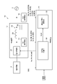
図1に表したように、電力変換装置10は、主回路部12と、制御装置14と、第1計測装置16と、第2計測装置18と、を備える。主回路部12は、電力の変換を行う。制御装置14は、主回路部12による電力の変換を制御する。
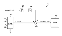
図2に表したように、過電流抑制制御部32は、dq逆変換部40と、過電流検出器42と、比例演算器44と、減算器46と、制御信号生成部48と、を有する。
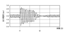
図4は、参考の電力変換装置の動作の一例を模式的に表すグラフである。
図4は、制御装置14が過電流抑制制御部32を有していない参考の電力変換装置の動作の一例を模式的に表す。
図3及び図4において、横軸は、時間(秒)であり、縦軸は、主回路部12の定格出力を基準とした出力電流(pu:per unit)である。
なお、上記実施形態と機能・構成上実質的に同じものについては、同符号を付し、詳細な説明は省略する。
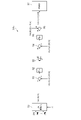
図5に表したように、過電流抑制制御部32aでは、過電流検出器42の入力が、第2計測装置18によって測定された主回路部12の交流電力の各相の線電流Ia(PCS)、Ib(PCS)、Ic(PCS)の測定値に置き換えられている。
図6に表したように、過電流抑制制御部32bは、dq逆変換部50と、第1減算器51と、第1比例演算器52と、リミッタ53と、第2減算器54と、第2比例演算器55と、加算器56と、制御信号生成部57と、を有する。
図7に表したように、過電流抑制制御部32cは、電圧推定部60と、dq逆変換部61と、第1減算器62と、第1比例演算器63と、第1加算器64と、リミッタ65と、第2減算器66と、第2比例演算器67と、第2加算器68と、制御信号生成部69と、を有する。
Claims (7)
- 入力された電力を交流電力に変換する電力変換部と、前記電力変換部から出力された前記交流電力を正弦波に近付けるフィルタ回路と、を有する主回路部と、
前記電力変換部の動作を制御することにより、前記主回路部による電力の変換を制御する制御装置と、
を備え、
前記制御装置は、
有効電力指令値及び無効電力指令値が入力されるとともに、前記主回路部の出力端の前記有効電力及び前記無効電力の各測定値が入力され、前記有効電力指令値と前記有効電力の測定値とを基に、前記主回路部から出力する前記交流電力の相電圧位相指令値を演算し、前記無効電力指令値と前記無効電力の測定値とを基に、前記主回路部から出力する前記交流電力の相電圧振幅指令値を演算する指令値演算部と、
前記相電圧位相指令値、前記相電圧振幅指令値、前記電力変換部の前記交流電力の相電圧及び線電流の各測定値、及び前記主回路部の前記交流電力の相電圧及び線電流の各測定値の各入力情報のいずれかを用いて、前記主回路部の出力端での過電流を抑制するように、前記電力変換部から出力する前記交流電力の各相の瞬時値電圧出力指令値を演算する過電流抑制制御部と、
を有し、演算した前記瞬時値電圧出力指令値に応じた電圧が前記電力変換部から出力されるように、前記電力変換部の動作を制御する電力変換装置。 - 前記過電流抑制制御部は、
前記相電圧位相指令値及び前記相電圧振幅指令値を基に、dq逆変換を行うことにより、前記主回路部から出力する前記交流電力の各相の瞬時値電圧の指令値を演算するdq逆変換部と、
前記電力変換部の前記交流電力の線電流の過電流の大きさを検出する過電流検出器と、
前記過電流検出器から入力された過電流の大きさに対して比例定数を乗算することにより、前記主回路部の前記交流電力の各相の瞬時値電圧の補正値を演算する比例演算器と、
前記比例演算器から入力された前記補正値を前記dq逆変換部から入力された前記主回路部の前記交流電力の各相の瞬時値電圧の指令値から減算することにより、減算結果を前記電力変換部の前記交流電力の前記各相の瞬時値電圧出力指令値として演算する減算器と、
を有する請求項1記載の電力変換装置。 - 前記過電流抑制制御部は、
前記相電圧位相指令値及び前記相電圧振幅指令値を基に、dq逆変換を行うことにより、前記主回路部から出力する前記交流電力の各相の瞬時値電圧の指令値を演算するdq逆変換部と、
前記主回路部の前記交流電力の線電流の過電流の大きさを検出する過電流検出器と、
前記過電流検出器から入力された過電流の大きさに対して比例定数を乗算することにより、前記主回路部の前記交流電力の各相の瞬時値電圧の補正値を演算する比例演算器と、
前記比例演算器から入力された前記補正値を前記dq逆変換部から入力された前記主回路部の前記交流電力の各相の瞬時値電圧の指令値から減算することにより、減算結果を前記電力変換部の前記交流電力の前記各相の瞬時値電圧出力指令値として演算する減算器と、
を有する請求項1記載の電力変換装置。 - 前記過電流抑制制御部は、
前記相電圧位相指令値及び前記相電圧振幅指令値を基に、dq逆変換を行うことにより、前記主回路部から出力する前記交流電力の各相の瞬時値電圧の指令値を演算するdq逆変換部と、
演算された前記各相の瞬時値電圧の指令値から前記主回路部の交流電力の各相の相電圧の測定値を差し引くことにより、前記各相の瞬時値電圧の指令値と前記各相の相電圧の測定値との差分を演算する第1減算器と、
前記第1減算器によって演算された前記差分に第1比例定数を乗算することにより、前記主回路部の交流電力の前記各相の相電圧を、演算された前記各相の瞬時値電圧の指令値に近付けるための、前記主回路部から出力される前記交流電力の各相の線電流の指令値を演算する第1比例演算器と、
前記各相の線電流の指令値が上限値以上である場合に、前記各相の線電流の指令値を前記上限値に制限するとともに、前記各相の線電流の指令値が下限値以下である場合に、前記各相の線電流の指令値を前記下限値に制限するリミッタと、
前記リミッタから入力された前記各相の線電流の指令値から前記主回路部の前記交流電力の各相の線電流Iaの測定値を差し引くことにより、前記各相の線電流の指令値と前記各相の線電流の測定値との差分を演算する第2減算器と、
前記第2減算器によって演算された前記差分に第2比例定数を乗算することにより、前記各相の線電流Iaの指令値に応じた電流を前記電力変換部から出力するための補正値を演算する第2比例演算器と、
前記主回路部の前記交流電力の前記各相の相電圧の測定値に前記補正値を加算することにより、前記電力変換部から出力する前記交流電力の前記各相の瞬時値電圧出力指令値を演算する加算器と、
を有する請求項1記載の電力変換装置。 - 前記過電流抑制制御部は、
前記電力変換部の前記交流電力の各相の線電流の測定値を基に、前記主回路部の前記交流電力の各相の相電圧の推定値を演算する電圧推定部と、
前記相電圧位相指令値及び前記相電圧振幅指令値を基に、dq逆変換を行うことにより、前記主回路部から出力する前記交流電力の各相の瞬時値電圧の指令値を演算するdq逆変換部と、
前記各相の瞬時値電圧の指令値から前記各相の相電圧の推定値を差し引くことにより、前記各相の瞬時値電圧の指令値と前記各相の相電圧の推定値との差分を演算する第1減算器と、
前記第1減算器によって演算された前記差分に第1比例定数を乗算することにより、前記主回路部の前記交流電力の各相の相電圧を前記各相の瞬時値電圧の指令値に近付けるための補正値を演算する第1比例演算器と、
前記電力変換部の前記交流電力の各相の線電流の測定値に前記第1比例演算器で演算された前記補正値を加算することにより、前記主回路部から出力される前記交流電力の各相の相電圧を前記各相の瞬時値電圧の指令値に近付けるために必要な前記電力変換部の前記交流電力の各相の線電流の指令値を演算する第1加算器と、
前記各相の線電流の指令値が上限値以上である場合に、前記各相の線電流の指令値を前記上限値に制限するとともに、前記各相の線電流の指令値が下限値以下である場合に、前記各相の線電流の指令値を前記下限値に制限するリミッタと、
前記リミッタから入力された前記各相の線電流の指令値から前記電力変換部の前記交流電力の各相の線電流の測定値を差し引くことにより、前記各相の線電流の指令値と前記各相の線電流の測定値との差分を演算する第2減算器と、
前記第2減算器によって演算された前記差分に第2比例定数を乗算することにより、前記各相の線電流の指令値に応じた電流を前記電力変換部から出力するための補正値を演算する第2比例演算器と、
前記各相の相電圧の推定値に前記第2比例演算器で演算された前記補正値を加算することにより、前記電力変換部から出力する前記交流電力の前記各相の瞬時値電圧出力指令値を演算する第2加算器と、
を有する請求項1記載の電力変換装置。 - 前記電圧推定部は、
前記相電圧位相指令値と、前記電力変換部の前記交流電力の各相の線電流の測定値と、に対してdq変換を行うことにより、前記相電圧位相指令値と、前記各相の線電流の測定値と、を基に、前記各相の線電流のd軸成分を表す電流信号と、前記各相の線電流のq軸成分を表す電流信号と、を演算する変換部と、
前記q軸成分を表す電流信号に-1を乗算する演算を行う係数演算器と、
前記相電圧位相指令値、前記d軸成分を表す電流信号、及び前記係数演算器で演算された後の前記q軸成分を表す電流信号に対してdq逆変換を行うことにより、前記d軸成分を表す電流信号及び前記q軸成分を表す電流信号を基に、三相の瞬時値電圧を演算する逆変換部と、
前記三相の瞬時値電圧に対して比例演算を行うことにより、前記三相の瞬時値電圧を基に、前記主回路部の前記交流電力の前記各相の相電圧の推定値を演算する比例制御演算器と、
を有する請求項5記載の電力変換装置。 - 入力された電力を交流電力に変換する電力変換部と、前記電力変換部から出力された前記交流電力を正弦波に近付けるフィルタ回路と、を有する主回路部を備えた電力変換装置に用いられ、前記電力変換部の動作を制御することにより、前記主回路部による電力の変換を制御する制御装置であって、
有効電力指令値及び無効電力指令値が入力されるとともに、前記主回路部の出力端の有効電力及び無効電力の各測定値が入力され、前記有効電力指令値と前記有効電力の測定値とを基に、前記主回路部から出力する前記交流電力の相電圧位相指令値を演算し、前記無効電力指令値と前記無効電力の測定値とを基に、前記主回路部から出力する前記交流電力の相電圧振幅指令値を演算する指令値演算部と、
前記相電圧位相指令値、前記相電圧振幅指令値、前記電力変換部の前記交流電力の相電圧及び線電流の各測定値、及び前記主回路部の前記交流電力の相電圧及び線電流の各測定値の各入力情報のいずれかを用いて、前記主回路部の出力端での過電流を抑制するように、前記電力変換部から出力する前記交流電力の各相の瞬時値電圧出力指令値を演算する過電流抑制制御部と、
を備え、
演算した前記瞬時値電圧出力指令値に応じた電圧が前記電力変換部から出力されるように、前記電力変換部の動作を制御する制御装置。
Priority Applications (5)
| Application Number | Priority Date | Filing Date | Title |
|---|---|---|---|
| EP21933076.8A EP4318918A1 (en) | 2021-03-25 | 2021-03-25 | Power conversion device and control device |
| AU2021436071A AU2021436071B2 (en) | 2021-03-25 | 2021-03-25 | Power conversion device and control device |
| PCT/JP2021/012723 WO2022201471A1 (ja) | 2021-03-25 | 2021-03-25 | 電力変換装置及び制御装置 |
| US17/922,601 US20230170782A1 (en) | 2021-03-25 | 2021-03-25 | Power conversion device and control device |
| JP2022564840A JP7289410B2 (ja) | 2021-03-25 | 2021-03-25 | 電力変換装置及び制御装置 |
Applications Claiming Priority (1)
| Application Number | Priority Date | Filing Date | Title |
|---|---|---|---|
| PCT/JP2021/012723 WO2022201471A1 (ja) | 2021-03-25 | 2021-03-25 | 電力変換装置及び制御装置 |
Publications (1)
| Publication Number | Publication Date |
|---|---|
| WO2022201471A1 true WO2022201471A1 (ja) | 2022-09-29 |
Family
ID=83396606
Family Applications (1)
| Application Number | Title | Priority Date | Filing Date |
|---|---|---|---|
| PCT/JP2021/012723 WO2022201471A1 (ja) | 2021-03-25 | 2021-03-25 | 電力変換装置及び制御装置 |
Country Status (5)
| Country | Link |
|---|---|
| US (1) | US20230170782A1 (ja) |
| EP (1) | EP4318918A1 (ja) |
| JP (1) | JP7289410B2 (ja) |
| AU (1) | AU2021436071B2 (ja) |
| WO (1) | WO2022201471A1 (ja) |
Citations (3)
| Publication number | Priority date | Publication date | Assignee | Title |
|---|---|---|---|---|
| JPH1111184A (ja) * | 1997-06-20 | 1999-01-19 | East Japan Railway Co | き電線補償用自励式インバータの制御方法 |
| JP2003009537A (ja) * | 2001-06-27 | 2003-01-10 | Hitachi Ltd | 電力変換装置 |
| WO2019130375A1 (ja) * | 2017-12-25 | 2019-07-04 | 三菱電機株式会社 | 電力変換装置 |
-
2021
- 2021-03-25 US US17/922,601 patent/US20230170782A1/en active Pending
- 2021-03-25 WO PCT/JP2021/012723 patent/WO2022201471A1/ja active Application Filing
- 2021-03-25 JP JP2022564840A patent/JP7289410B2/ja active Active
- 2021-03-25 EP EP21933076.8A patent/EP4318918A1/en active Pending
- 2021-03-25 AU AU2021436071A patent/AU2021436071B2/en active Active
Patent Citations (3)
| Publication number | Priority date | Publication date | Assignee | Title |
|---|---|---|---|---|
| JPH1111184A (ja) * | 1997-06-20 | 1999-01-19 | East Japan Railway Co | き電線補償用自励式インバータの制御方法 |
| JP2003009537A (ja) * | 2001-06-27 | 2003-01-10 | Hitachi Ltd | 電力変換装置 |
| WO2019130375A1 (ja) * | 2017-12-25 | 2019-07-04 | 三菱電機株式会社 | 電力変換装置 |
Also Published As
| Publication number | Publication date |
|---|---|
| JPWO2022201471A1 (ja) | 2022-09-29 |
| US20230170782A1 (en) | 2023-06-01 |
| AU2021436071A1 (en) | 2022-12-01 |
| EP4318918A1 (en) | 2024-02-07 |
| JP7289410B2 (ja) | 2023-06-09 |
| AU2021436071B2 (en) | 2023-08-31 |
Similar Documents
| Publication | Publication Date | Title |
|---|---|---|
| JP5259077B2 (ja) | 瞬時電圧低下補償回路、電力変換装置、瞬時電圧低下補償方法及び瞬時電圧低下補償プログラム | |
| KR101494453B1 (ko) | 전력변환장치의 고조파전류억제장치 및 고조파전류억제방법 | |
| AU2011202989B2 (en) | System and method for control of multiphase power converters | |
| WO2009123268A1 (ja) | 系統安定化装置 | |
| EP2763301B1 (en) | Power converter control method | |
| JP4935617B2 (ja) | アクティブフィルタ機能装置 | |
| KR20140031763A (ko) | 회생형 인버터 장치 및 단위 전력 셀을 이용한 인버터 장치 | |
| KR20170107277A (ko) | 3상 시스템의 전류 불평형 보상 기능을 갖는 에너지 저장장치 | |
| CN113497451A (zh) | 系统互连逆变器以及系统频率的变动抑制方法 | |
| US11063530B2 (en) | Method for removing direct current component at output terminal of MMC converter | |
| JP2014128178A (ja) | 電力変換制御装置 | |
| JP7289410B2 (ja) | 電力変換装置及び制御装置 | |
| JP7289409B2 (ja) | 電力変換装置及び制御装置 | |
| KR20130032429A (ko) | 위상 동기 루프 회로 | |
| US11942876B2 (en) | Power conversion device | |
| US20190214918A1 (en) | Power supply system | |
| JP3598871B2 (ja) | 単独運転検出機能を有する系統連系用電力変換システム | |
| JP6342354B2 (ja) | 単独運転検出装置、単独運転検出装置の制御方法および系統連系インバータ | |
| JP2019221040A (ja) | 系統連系インバータ装置及び安定化制御方法 | |
| JP2019140743A (ja) | 電力変換装置 | |
| JP4533674B2 (ja) | 電力変換装置 | |
| KR102586189B1 (ko) | 전기자동차용 영구자석 동기전동기의 고효율 운전 제어 장치 및 그 제어 방법 | |
| JP6018792B2 (ja) | 電力変換装置の制御方法 | |
| KR101852015B1 (ko) | 하이브리드 비례 적분 제어기 및 그 제어기를 갖는 인버터 시스템 | |
| KR20190029091A (ko) | 배터리 충전 장치 |
Legal Events
| Date | Code | Title | Description |
|---|---|---|---|
| ENP | Entry into the national phase |
Ref document number: 2022564840 Country of ref document: JP Kind code of ref document: A |
|
| 121 | Ep: the epo has been informed by wipo that ep was designated in this application |
Ref document number: 21933076 Country of ref document: EP Kind code of ref document: A1 |
|
| ENP | Entry into the national phase |
Ref document number: 2021436071 Country of ref document: AU Date of ref document: 20210325 Kind code of ref document: A |
|
| WWE | Wipo information: entry into national phase |
Ref document number: 2021933076 Country of ref document: EP |
|
| NENP | Non-entry into the national phase |
Ref country code: DE |
|
| ENP | Entry into the national phase |
Ref document number: 2021933076 Country of ref document: EP Effective date: 20231025 |