WO2016143342A1 - エンドキャップ及びそれを備えた直動案内装置 - Google Patents
エンドキャップ及びそれを備えた直動案内装置 Download PDFInfo
- Publication number
- WO2016143342A1 WO2016143342A1 PCT/JP2016/001304 JP2016001304W WO2016143342A1 WO 2016143342 A1 WO2016143342 A1 WO 2016143342A1 JP 2016001304 W JP2016001304 W JP 2016001304W WO 2016143342 A1 WO2016143342 A1 WO 2016143342A1
- Authority
- WO
- WIPO (PCT)
- Prior art keywords
- oil passage
- oil
- end cap
- path
- supply hole
- Prior art date
- Legal status (The legal status is an assumption and is not a legal conclusion. Google has not performed a legal analysis and makes no representation as to the accuracy of the status listed.)
- Ceased
Links
Images







Classifications
-
- F—MECHANICAL ENGINEERING; LIGHTING; HEATING; WEAPONS; BLASTING
- F16—ENGINEERING ELEMENTS AND UNITS; GENERAL MEASURES FOR PRODUCING AND MAINTAINING EFFECTIVE FUNCTIONING OF MACHINES OR INSTALLATIONS; THERMAL INSULATION IN GENERAL
- F16C—SHAFTS; FLEXIBLE SHAFTS; ELEMENTS OR CRANKSHAFT MECHANISMS; ROTARY BODIES OTHER THAN GEARING ELEMENTS; BEARINGS
- F16C29/00—Bearings for parts moving only linearly
- F16C29/04—Ball or roller bearings
- F16C29/06—Ball or roller bearings in which the rolling bodies circulate partly without carrying load
Definitions
- the present invention relates to an end cap and a linear motion guide device including the same, and particularly to an end cap formed with an oil passage and a linear motion guide device including the same.
- linear motion guide devices used in general-purpose, machine tools and the like ensure a running life by periodically supplying a lubricant.
- This linear motion guide device is often used in various lubrication positions (front, top, side) and postures (wall hanging, vertical), and is a stable lubricant regardless of the lubrication position and the posture of the linear motion guide device. Need to be replenished.
- lubrication may not be successful due to the influence of the vertical force, especially the oil lubrication position of the oil (oil) lubrication is on the side, or the linear motion guide device is in a wall-mounted position. In such a case, an imbalance in supply amount due to the rolling train tends to occur.
- Patent Literature 2 and Patent Literature 3 are related to a linear motion guide device that can supply a lubricant regardless of an oil supply position or an attitude of the linear motion guide device. Is disclosed. These technologies connect the oil passages connecting the supply ports provided in the end caps and the oil passages connecting the left and right rolling element circulation paths, and supply the lubricant supplied from the supply ports to the left and right rolling element circulations. This is a linear motion guide device supplied to the road.
- Patent Document 2 is provided with a tube for supplying a lubricant, and by securing an independent path from the oil supply position to the lubricant supply destination (each rolling element circulation path), The lubricant can be supplied regardless of the posture of the motion guide device. Further, the technique disclosed in Patent Document 3 also secures an independent path from an oil supply position to a lubricant supply destination (each rolling element circulation path) by providing a plug in the oil path. The lubricant can be supplied regardless of the position and the attitude of the linear motion guide device.
- the route of the lubricant is once formed upward from the side surface supply portion (nipple hole) (the direction in which the slider is installed with reference to the guide rail). .
- a lubricant path for example, in the case of oil lubrication, since it opposes gravity, it is disadvantageous for flow.
- an oil passage connecting each supply port provided on both side surfaces of the end cap, and each of the left and right sides It has become difficult to separate and form the oil passages that connect the rolling element circulation passages, and there is room for improvement in terms of reduction in productivity and product accuracy.
- an object of the present invention is to provide an end cap capable of efficiently supplying a lubricant to the rolling element circulation path and a linear motion guide device including the end cap.
- An aspect of the end cap for achieving the above object is formed between the guide rail and the slider body, and is joined to the end surface in the moving direction of the slider body that is movably supported on the guide rail.
- a direction changing path for communicating the load rolling path and the rolling element return path of the slider body An oil passage is formed that communicates the front oil supply hole and the side oil supply hole formed on the outer peripheral surface with the direction change path,
- the end cap includes an end cap body having a part of the direction change path and the oil path, and an oil path unit having a part of the oil path,
- the end cap body is formed on a joint surface with the slider body and can be fitted with the oil passage unit, and is formed on a joint surface with the slider body, and communicates the direction changing path and the recess.
- the oil passage unit has a third oil passage that communicates between the first oil passage and the second oil passage through the front oil supply hole in a state of being fitted in the recess,
- the second oil passage and the third oil passage are arranged so as to overlap along the moving direction of the slider body in the end cap body.
- the end cap is joined to the end surface in the moving direction of the slider main body, which is movably supported on the guide rail, and between the guide rail and the slider main body.
- a direction change path that communicates the formed load rolling path and the rolling element return path of the slider body;
- An oil passage is formed that communicates the front oil supply hole and the side oil supply hole formed on the outer peripheral surface with the direction change path,
- the end cap includes an end cap body having a part of the direction change path and the oil path, and an oil path unit having a part of the oil path,
- the end cap body is formed on a joint surface with the slider body and can be fitted with the oil passage unit, and is formed on a joint surface with the slider body, and communicates the direction changing path and the recess.
- a first oil passage to Have The oil passage unit includes a second oil passage communicating the first oil passage and the side surface oil supply hole; A first oil passage fitted in the recess, and a third oil passage communicating with the second oil passage through the front oil supply hole;
- the second oil passage and the third oil passage are arranged so as to overlap along the moving direction of the slider body in the end cap body.
- the second oil passage may be composed only of an inclined oil passage that is inclined downward.
- a mode of the linear motion guide device for achieving the above object includes a guide rail having a rail-side rolling surface extending in the longitudinal direction on the outer surface, and a slider body that is straddled to be relatively movable on the guide rail, And a slider having end caps provided on both end faces in the moving direction of the slider body, The end cap is joined to the moving direction end surface of the slider main body, which is movably straddled on the guide rail, and is formed between the guide rail and the slider main body and the slider main body.
- a direction change path that communicates with the rolling element return path of An oil passage is formed that communicates the front oil supply hole and the side oil supply hole formed on the outer peripheral surface with the direction change path
- the end cap includes an end cap body having a part of the direction change path and the oil path, and an oil path unit having a part of the oil path
- the end cap body is formed on a joint surface with the slider body and can be fitted with the oil passage unit, and is formed on a joint surface with the slider body, and communicates the direction changing path and the recess.
- the oil passage unit has a third oil passage that communicates between the first oil passage and the second oil passage through the front oil supply hole in a state of being fitted in the recess,
- the second oil passage and the third oil passage are arranged so as to overlap along the moving direction of the slider body in the end cap body.
- a guide rail having a rail-side rolling surface extending in the longitudinal direction on an outer surface, and a slider main body straddling the guide rail so as to be relatively movable.
- a slider having end caps provided on both end faces in the moving direction of the slider body, The end cap is joined to an end surface of the slider main body that is movably straddled over the guide rail, and a load rolling path formed between the guide rail and the slider main body and the slider main body are connected to each other.
- a direction change path that communicates with the rolling element return path having An oil passage is formed that communicates the front oil supply hole and the side oil supply hole formed on the outer peripheral surface with the direction change path
- the end cap includes an end cap body having a part of the direction change path and the oil path, and an oil path unit having a part of the oil path
- the end cap body is formed on a joint surface with the slider body and can be fitted with the oil passage unit, and is formed on a joint surface with the slider body, and communicates the direction changing path and the recess.
- a first oil passage to Have The oil passage unit includes a second oil passage communicating the first oil passage and the side surface oil supply hole; A first oil passage fitted in the recess, and a third oil passage communicating with the second oil passage through the front oil supply hole;
- the second oil passage and the third oil passage are arranged so as to overlap along the moving direction of the slider body in the end cap body.
- the second oil passage may be composed only of an inclined oil passage that is inclined downward.
- the end cap is joined to the end surface in the moving direction of the slider main body, which is movably supported on the guide rail, and between the guide rail and the slider main body.
- a direction change path that communicates the formed load rolling path and the rolling element return path of the slider body;
- An oil passage that connects the upper surface oil supply hole, the front oil supply hole and the side oil supply hole formed on the outer peripheral surface and the direction change path is formed,
- An end cap body having a part of the direction change path and the oil path, and a plurality of oil path units having a part of the oil path,
- the end cap body is formed on a joint surface between the slider body and a recess formed on a joint surface with the slider body and capable of fitting a plurality of the oil passage units in a thickness direction, and the direction change.
- the oil passage unit has a sixth oil passage that communicates the first oil passage, the fourth oil passage, and the fifth oil passage on the front surface, and the first oil passage and the first oil passage on the back surface.
- a seventh oil passage communicating with the two oil passages.
- the end cap is joined to the end surface in the moving direction of the slider main body, which is movably supported on the guide rail, and between the guide rail and the slider main body.
- a direction change path that communicates the formed load rolling path and the rolling element return path of the slider body;
- An oil passage that connects the upper surface oil supply hole, the front oil supply hole and the side oil supply hole formed on the outer peripheral surface and the direction change path is formed,
- An end cap body having a part of the direction change path and the oil path, and a plurality of oil path units having a part of the oil path,
- the end cap body is formed on a joint surface between the slider body and a recess formed on a joint surface with the slider body and capable of fitting a plurality of the oil passage units in a thickness direction, and the direction change.
- the oil passage unit has a sixth oil passage that communicates the first oil passage, the fourth oil passage, and the fifth oil passage on the front surface, and two first oil passages on the back surface. And a second oil passage communicating with each of the two second oil passages on one side surface.
- the two oil passage units may be overlapped with their surfaces facing each other and fitted into the recess.
- the end cap may be provided with an extension portion in which at least one of the sixth oil passage and the seventh oil passage projects into the first oil passage.
- a guide rail having a rail-side rolling surface extending in the longitudinal direction on an outer surface, and a slider main body straddling the guide rail so as to be relatively movable.
- a slider having end caps provided on both end faces in the moving direction of the slider body, The end cap is joined to the moving direction end surface of the slider main body, which is movably straddled on the guide rail, and is formed between the guide rail and the slider main body and the slider main body.
- a direction change path that communicates with the rolling element return path of An oil passage is formed that communicates the front oil supply hole and the side oil supply hole formed on the outer peripheral surface with the direction change path
- the end cap includes an end cap body having a part of the direction change path and the oil path, and a plurality of oil path units having a part of the oil path
- the end cap body is formed on a joint surface between the slider body and a recess formed on a joint surface with the slider body and capable of fitting a plurality of the oil passage units in a thickness direction, and the direction change.
- the oil passage unit has a sixth oil passage that communicates the first oil passage, the fourth oil passage, and the fifth oil passage on the front surface, and the first oil passage and the first oil passage on the back surface.
- a seventh oil passage communicating with the two oil passages.
- a guide rail having a rail-side rolling surface extending in the longitudinal direction on an outer surface, and a slider main body straddling the guide rail so as to be relatively movable.
- a slider having end caps provided on both end faces in the moving direction of the slider body, The end cap is joined to an end surface of the slider main body that is movably straddled over the guide rail, and a load rolling path formed between the guide rail and the slider main body and the slider main body are connected to each other.
- a direction change path that communicates with the rolling element return path having An oil passage that connects the upper surface oil supply hole, the front oil supply hole and the side oil supply hole formed on the outer peripheral surface and the direction change path is formed,
- the end cap includes an end cap body having a part of the direction change path and the oil path, and a plurality of oil path units having a part of the oil path,
- the end cap body is formed on a joint surface between the slider body and a recess formed on a joint surface with the slider body and capable of fitting a plurality of the oil passage units in a thickness direction, and the direction change.
- the oil passage unit has a sixth oil passage that communicates the first oil passage, the fourth oil passage, and the fifth oil passage on the front surface, and two first oil passages on the back surface. And a second oil passage communicating with each of the two second oil passages on one side surface.
- the two oil passage units of the end cap may be overlapped with the surfaces facing each other and fitted into the recess.
- an extension part in which at least one of the sixth oil passage and the seventh oil passage of the end cap protrudes into the first oil passage may be provided.
- an end cap capable of efficiently supplying a lubricant to the rolling element circulation path and a linear motion guide device including the end cap.
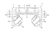
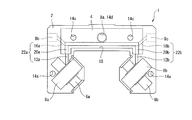
- FIG. 1 It is a perspective view which shows the structure in 1st Embodiment of a linear guide apparatus. It is a rear view which shows the structure in 1st Embodiment of an end cap. It is a figure which shows the structure in 1st Embodiment of an end cap, (a) is a rear view of an oil-path unit, (b) is a rear view of an end cap main body. It is a figure which shows the structure in 1st Embodiment of an end cap, (a) is a side view of an oil-path unit, (b) is a side view of an end cap main body.
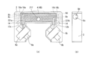
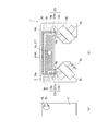
- FIG. 1 It is a figure which shows the structure in 3rd Embodiment of an end cap, (a) is a rear view of an oil path unit, (b) is a front view of an oil path unit, (c) is a rear view of an end cap main body. It is a figure which shows the structure in 3rd Embodiment of an end cap, (a) is a side view of an oil-path unit, (b) is a side view of an end cap main body. It is a rear view which shows the structure in the modification of 3rd Embodiment of an end cap. It is a perspective view which shows the structure in 4th Embodiment of a linear guideway. It is a rear view which shows the structure in 4th Embodiment of an end cap.
- the linear motion guide device 100 includes a guide rail 110 having a rail-side rolling surface 111 extending in the longitudinal direction on the outer surface, and a slider 120 straddling the guide rail 110 so as to be relatively movable.
- the slider 120 includes a slider main body 120A and end caps 1 that are joined to both end faces of the slider main body 120A in the moving direction by joint members 122, respectively.
- the slider main body 120A has a U-shaped cross section, and both sleeve portions have slider-side rolling surfaces (not shown) facing the rail-side rolling surfaces 111, respectively. It has a rolling element return path (not shown) that penetrates the thick portion in the moving direction of the slider body 120A.
- a load rolling path is formed between the rail-side rolling surface 111 and the slider-side rolling surface.
- the joining member 122 is formed by, for example, a screw, and is inserted into both sleeve portion side through holes and an oil passage unit mounting through hole, which will be described later, and detachably couples the end cap 1 to the slider body 120A. .
- an end cap provided in a linear motion guide device using cylindrical rollers as rolling elements will be described as an example.
- the steel ball may be used as the rolling element.
- an end cap provided in a linear motion guide device including two rows of rolling element circulation paths on the left and right sides will be described as an example.
- the configuration of the linear motion guide device is not limited to this. For example, it is good also as a structure provided with the rolling element circuit of 1 row of right and left, and good also as a structure provided with the rolling element circuit of 3 or more rows on the left and right.
- the end cap 1 of the present embodiment is an end cap provided in the linear motion guide device 100 described above, and the “back surface” of the end cap 1 shown in FIG. 2 indicates a joint surface with the slider main body 120A.
- a surface facing (joining) the slider main body 120A is referred to as a “rear surface” and the opposite surface is a front surface.
- the end cap 1 includes an end cap body 2 and an oil passage unit 4.
- the end cap body 2 is formed in a U-shaped cross section using, for example, a hard resin material, and the direction change path 6, an oil supply hole 8, a recess 10, a first oil passage 12, a through hole 14, and a second oil passage 16.
- the direction change path 6 is formed as direction change paths 6a and 6b on both sleeves, respectively, and communicates a load rolling path and a rolling element return path formed between the guide rail 110 and the slider body 120A. ing.
- the oil supply hole 8 is formed on the outer peripheral surface of the end cap body 2 other than the joint surface with the slider main body 120A.
- the three oil supply holes 8 include a front oil supply hole 8a formed on the surface of the end cap body 2 opposite to the joint surface with the slider body, and a left side surface of the end cap body 2 (on both side surfaces of the end cap body 2).
- the left side oil supply hole 8b formed in the left side surface in FIG. 2 and the right side surface of the end cap body 2 (the right side surface in FIG. 2 of both side surfaces of the end cap body 2) are formed.
- Right side oil supply hole 8c is formed on the outer peripheral surface of the end cap body 2 other than the joint surface with the slider main body 120A.
- the concave portion 10 is formed on the joint surface of the end cap body 2 with the slider body, and is formed in a shape into which the oil passage unit 4 can be fitted.
- the recess 10 is opposed to the oil supply holes 8a to 8c with the thin portion of the end cap body 2 formed between the recess 10 and each of the oil supply holes 8a to 8c being removed. In this state, the oil supply holes 8a to 8c communicate with each other.
- the oil supply holes 8a to 8c only the front oil supply hole 8a, that is, only the oil supply hole 8 arranged between both side surfaces of the end cap body 2 communicates with the recess 10. explain.
- the first oil passage 12 is, for example, a concave groove formed on the joint surface of the end cap body 2 with the slider body, and communicates the concave portion 10 with the direction change paths 6 formed on both sleeve portions, respectively. ing.
- the first oil passage 12 that communicates the recess 10 and the direction change path 6a is referred to as a first oil path 12a
- the first oil passage 12 communicates between the recess 10 and the direction change path 6b.
- the oil passage 12 is referred to as a first oil passage 12b.
- the through-hole 14 includes two sleeve-side through-holes 14a formed in the sleeve portions, and two recess-side through-holes (not shown).
- Each sleeve-side through hole 14a and each recess-side through hole both penetrate the end cap body 2 in the direction of movement of the slider body.
- a joining member (not shown) formed by a screw is inserted therethrough. It is formed in a possible shape.
- each sleeve side through hole 14a and each recess side through hole are formed on the end surface in the moving direction of the slider main body, and four slider side mounting holes (not shown) into which the front end side of the joining member fits. And corresponding positions. The configuration of the recess-side through hole will be described later.
- the second oil passage 16 is, for example, a concave groove formed on the joint surface of the end cap body 2 with the slider body, and includes a left side oil supply hole 8b and a front oil supply hole. 8a communicates with the right side oil supply hole 8c.
- the second oil passage 16 is, for example, an inclined oil passage 16A inclined downward from the left side oil supply hole 8b (side where the guide rail 110 is located), and downward from the right side oil supply hole 8c (the guide rail 110 is A connecting oil passage 16C that communicates with the inclined oil passage 16B that inclines toward the side) and the front oil supply hole 8a, is formed flat in the width direction of the end cap body 2, and connects the inclined oil passages 16A and 16B. Consists of
- the oil passage unit 4 is formed in a plate shape that fits into the recess 10 using, for example, a resin material such as a thermoplastic elastomer.
- the through hole 14d is a through hole that communicates with the front oil supply hole 8a.
- the third oil passage 20 is formed on the surface opposite to the surface facing the slider body 120A of the oil passage unit 4 in a state in which the oil passage unit 4 is fitted in the recess 10, for example, by a concave groove. Is formed. Further, the third oil passage 20 communicates the front oil supply hole 8a and the through hole 14d with the first oil passages 12a and 12b in a state where the oil passage unit 4 is fitted in the recess 10. Here, the third oil passage 20 is arranged in the oil passage unit 4 so as to overlap with the second oil passage 16 along the moving direction of the slider main body 120A in the end cap main body 2.
- the third oil passage 20 that connects the front oil supply hole 8a and the through hole 14d and the first oil passage 12a is referred to as a third oil passage 20a, and the front oil supply hole 8a and the through oil supply hole 8a.
- the third oil passage 20 that communicates the hole 14d with the first oil passage 12b is referred to as a third oil passage 20b.
- the oil passage unit 4 when the oil passage unit 4 is fitted into the recess 10, the first oil passage 12a, the third oil passage 20a, the second oil passage 16a, and the first oil passage 12b, the third oil passage 20b, The second oil passage 16a communicates to form an oil passage 22 that communicates the front oil supply hole 8a and the direction change passages 6a and 6b.
- the oil passage 22 that communicates the front oil supply hole 8a and the direction change path 6a is referred to as an oil path 22a
- the oil passage 22 that communicates the front oil supply hole 8a and the direction change path 6b It is described as an oil passage 22b.
- the oil passage unit side through hole 14c penetrates the oil passage unit 4 in the movement direction of the slider body, and the movement direction of the recess side through hole and the slider body in the state where the oil passage unit 4 is fitted into the recess 10. It is formed at a position overlapping when viewed from above.
- the oil passage unit side through hole 14c and the recess side through hole are communicated to form an oil passage unit mounting through hole.
- the second oil passage and the third oil passage are arranged so as to overlap along the moving direction of the slider body in the end cap body.
- the degree of freedom in designing the oil passage is high and the change is easy.
- the route from the side supply hole to the front supply hole to the direction change path on the oil passage unit can be arranged at the same height, and there is an advantage that it is not necessary to make a route upward from the side supply hole.
- the second oil passage 16 provided in the end cap body 2 is not provided with the connecting oil passage 16C as shown in FIG. It is good also as a structure which consists of the path
- Examples of the synthetic resin include plastics and thermoplastic elastomers.
- Examples of the plastic include POM, and examples of the thermoplastic elastomer include an oil-resistant polyamide-based elastomer or polystyrene-based elastomer.
- the end cap 1 of the present embodiment is similar to the first embodiment in that the first oil passage 12 communicates with the direction change passage 6 that is a member constituting a part of the rolling element circulation passage.
- the second oil passage 16 communicating with the side surface supply holes 8b and 8c is connected to the third oil passage 20 via the front oil supply hole 8a or the through hole 14d.
- a third oil passage 20 communicating with the first oil passage 12 is formed on the back surface of the oil passage unit 4.
- a second oil passage 16 communicating with the side surface supply holes 8 b and 8 c is formed in the front of the oil passage unit 4.
- no oil passage is formed in the recess 10 of the end cap body 2.
- the communication groove 17 that communicates with the side surface supply holes 8 b and 8 c is provided so as to open on the side surface of the recess 10.
- the second oil passage 16 provided in the oil passage unit 4 is not provided with the connecting oil passage 16C as shown in FIG. 8B, and the inclined oil passage 16A and the inclined oil passage 16B. It is good also as a structure which communicates with the through-hole 14d by these connection parts. With such a configuration, the lubricant can be smoothly provided to the rolling element circulation path.
- the end cap 1 of the present embodiment is similar to the first embodiment in that the first oil passage 12 communicates with the direction change passage 6 that is a member constituting a part of the rolling element circulation passage.
- the second oil passage 16 communicating with the side surface supply holes 8b and 8c is connected to the third oil passage 20 via the front oil supply hole 8a or the through hole 14d.
- a third oil passage 20 communicating with the first oil passage 12 is formed on the back surface of the oil passage unit 4.
- a second oil passage 16 communicating with the side surface supply holes 8b and 8c is formed in the front face of the oil passage unit 4.
- a fourth oil passage 18 is formed in the recess 10 of the end cap body 2. The fourth oil passage 18 is also provided in the same manner as the second oil passage 16 in the first embodiment. Further, when the oil passage unit 4 is fitted into the recess 10, the second oil passage 16 provided in the oil passage unit 4 and the fourth oil passage 18 provided in the recess 10 are moved by the slider 120.
- the inclined oil passages 16A and 18A, the inclined oil passages 16B and 18B, and the connecting oil passages 16C and 18C are in the same shape and communicated so as to expand in the slider moving direction (the thickness direction of the end cap body 2). Be placed.
- the oil passage that communicates the side surface supply holes 8b and 8c and the through hole 14d (front supply hole 8a) is constituted by the second oil passage 16 and the fourth oil passage 18. Therefore, the lubricant can be supplied more efficiently to the rolling element circulation path even if the size is reduced.
- the second oil passage 16 provided in the end cap body 2 includes the inclined oil passage 16 ⁇ / b> A and the inclined oil passage 16 ⁇ / b> B without providing the connecting oil passage 16 ⁇ / b> C as shown in FIG. It is good also as a structure connected to the front oil supply hole 8a by these connection parts.
- the third oil passage 20 communicating with the first oil passage 12 and the second oil passage 16 communicating with the left side oil supply hole 8b and the right side oil supply hole 8c are front-facing. It has the structure arrange
- the linear motion guide device of the present embodiment is suitable for a linear motion guide device used in general machine devices such as machine tools and conveyor devices.
- the linear motion guide device 100 includes a guide rail 110 having a rail-side rolling surface 111 extending in the longitudinal direction on the outer surface, and a slider 120 straddling the guide rail 110 so as to be relatively movable.
- the slider 120 includes a slider main body 120A and end caps 1 that are joined to both end faces of the slider main body 120A in the moving direction by joint members 122, respectively.
- the slider main body 120A has a U-shaped cross section, and both sleeve portions have slider-side rolling surfaces (not shown) facing the rail-side rolling surfaces 111, respectively. It has a rolling element return path (not shown) that penetrates the thick portion in the moving direction of the slider body 120A.
- a load rolling path is formed between the rail-side rolling surface 111 and the slider-side rolling surface.
- the joining member 122 is formed by, for example, a screw, and is inserted into both sleeve portion side through holes and an oil passage unit mounting through hole, which will be described later, and detachably couples the end cap 1 to the slider body 120A. .
- an end cap provided in a linear motion guide device using cylindrical rollers as rolling elements will be described as an example.
- the steel ball may be used as the rolling element.
- an end cap provided in a linear motion guide device including two rows of rolling element circulation paths on the left and right sides will be described as an example.
- the configuration of the linear motion guide device is not limited to this. For example, it is good also as a structure provided with the rolling element circuit of 1 row of right and left, and good also as a structure provided with the rolling element circuit of 3 or more rows on the left and right.
- the end cap 1 of the present embodiment is an end cap provided in the above-described linear motion guide device 100, and the “back surface” of the end cap 1 shown in FIG. 15 refers to a joint surface with the slider main body 120A.
- a surface facing (joining) the slider main body 120A is referred to as a “rear surface” and the opposite surface is a front surface.
- the end cap 1 includes an end cap body 2 and an oil passage unit 4.
- the end cap body 2 has a U-shaped cross section using, for example, a hard resin material.
- the end cap body 2 includes a direction change path 6, an oil supply hole 8, a recess 10, a first oil path 12, a through hole 14, a second oil path 16, a fourth oil path 217, And a fifth oil passage 218.
- the direction change path 6 is formed as direction change paths 6a and 6b on both sleeves, respectively, and communicates a load rolling path and a rolling element return path formed between the guide rail 110 and the slider body 120A. ing.
- the oil supply hole 8 is formed on the outer peripheral surface of the end cap body 2 other than the joint surface with the slider main body 120A.
- the four oil supply holes 8 are formed in the front oil supply hole 8a formed on the surface of the end cap body 2 opposite to the joint surface with the slider main body, side supply holes 8b to 8e, and the upper surface of the end cap main body 2.
- the upper surface supply hole 8f is formed on the left side surface of the end cap body 2 (the left side surface in FIG. 15 among the both side surfaces of the end cap body 2).
- two right side surface oil supply holes 8d and 8e formed on the right side surface of the end cap body 2 (the right side surface in FIG. 15 among both side surfaces of the end cap body 2).
- the recess 10 is formed on the joint surface of the end cap body 2 with the slider body, and is formed in a shape in which a plurality of oil passage units 4 stacked in the thickness direction can be fitted.
- the “thickness direction” of the oil passage unit 4 is an axial direction connecting a front surface and a back surface described later.
- the recess 10 is opposed to the oil supply holes 8a to 8f with the thin part of the end cap body 2 formed between the recess 10 and each of the oil supply holes 8a to 8f, and the thin part is removed. In this state, the oil supply holes 8a to 8f communicate with each other.
- the first oil passage 12 is, for example, a concave groove formed on the joint surface of the end cap body 2 with the slider body, and communicates the concave portion 10 with the direction change paths 6 formed on both sleeve portions, respectively. ing.
- the first oil passage 12 that communicates the recess 10 and the direction change path 6a is referred to as a first oil path 12a, and the first oil passage 12 communicates between the recess 10 and the direction change path 6b.
- the oil passage 12 may be described as the first oil passage 12b.
- the through-hole 14 includes two sleeve-side through-holes 14 formed in both sleeve portions, and two recess-side through-holes (not shown).
- Both the sleeve-side through holes 14 and the recess-side through holes both penetrate the end cap body 2 in the direction of movement of the slider body.
- a joining member (not shown) formed by a screw is inserted therethrough. It is formed in a possible shape.
- each sleeve-side through-hole 14 is formed at a position corresponding to four slider-side mounting holes (not shown) that are formed on the end surface of the slider body in the moving direction and to which the front end side of the joining member is fitted. Has been.
- the second oil passage 16 is, for example, a concave groove formed on the joint surface of the end cap body 2 with the slider body, and the left side oil supply holes 8b to 8e. And the recess 10 are communicated with each other. Specifically, the second oil passage 16 communicates the second oil passage 16a that communicates the left side oil supply holes 8b and 8c with the recess 10 and the right oil supply holes 8d and 8e and the recess 10 communicated with each other. 2 oil passages 16b. [Fourth oil passage] As shown in FIGS.
- the fourth oil passage 217 is, for example, a concave groove formed on the joint surface of the end cap body 2 with the slider body, and includes the front oil supply hole 8a and the recess 10. And communicate with.
- the fifth oil passage 218 is, for example, a concave groove formed on the joint surface of the end cap body 2 with the slider body, and the upper surface oil supply hole 8 f and the recess 10. And communicate with.
- the oil passage unit 4 is made of, for example, a resin material such as a thermoplastic elastomer, and is a plate that fits into the recess 10 in a plurality of layers in the thickness direction. It is formed into a shape.
- a sixth oil passage 220 is formed on the front surface 4 a of one oil passage unit 4, and the sixth oil passage 220 is formed on the back surface 4 b of one oil passage unit 4. Seven oil passages 221 are formed.
- the plurality of oil passage units 4 fitted (accommodated) in the recesses 10 are respectively provided with the same sixth oil passage 220 and seventh oil passage on the front surface 4a and the back surface 4b.
- the front surfaces 4a and 4A and the back surfaces 4b and 4B are disposed in the recess 10 so as to face each other.
- the sixth oil passage 220 is a state in which the oil passage unit 4 is fitted in the recess 10, and the first oil passage 12, the fourth oil passage 217, and the fifth oil passage as shown in FIG. It is formed on the front surface 4 a of the oil passage unit 4 as a concave groove communicating with the passage 218.
- the seventh oil passage 221 is a concave groove that communicates the two first oil passages 12 and 12 with the two second oil passages 16 and 16 on one side surface, respectively. Is formed on the back surface 4b of the oil passage unit 4.
- the sixth oil passage 220a formed on the front surface 4a of the one oil passage unit 4A includes the first oil passages 12a and 12b, the fourth oil passage 217, and the fifth oil passage 217. It communicates with the oil passage 218.
- the seventh oil passage 221a formed on the back surface 4b of the one oil passage unit 4A is connected to the first oil passage 12a and the side oil supply hole 8c that opens to one side surface.
- the second oil passage 16a communicates with the first oil passage 12b and the second oil passage 16a connected to the side surface oil supply hole 8b opened on one side surface.
- the seventh oil passage 221a formed on the back surface 4b of the other oil passage unit 4B is connected to the first oil passage 12b and the side oil supply hole 8e that opens to the other side surface. While communicating with the oil passage 16b, it communicates with the first oil passage 12a and the second oil passage 16b connected to the side surface oil supply hole 8d that opens to the other side surface.
- the sixth oil passage 220a formed on the front surface 4a includes the first oil passages 12a and 12b and the fourth oil passage 217. And a fifth oil passage 218.
- the oil passage unit 4 having the same specification (standard) in which the sixth oil passage 220 is formed on the front surface 4a and the seventh oil passage 221 is formed on the back surface 4b is thick. It is accommodated in the recess 10 of the end cap body 2 in the vertical direction. Therefore, since the communication mode of the oil passage 22 is functionally separated by the sixth oil passage 220 and the seventh oil passage 221, the lubricant can be supplied regardless of the oil supply position and the attitude of the linear motion guide device. Further, since the oil passage unit 4 having the same specification (standard) is used, the manufacturing cost can be reduced and assembly errors can be reduced. Furthermore, since a plurality of oil passage units 4 are used, the degree of freedom in designing the oil passage is high and the change is easy.
- the seventh oil passage 221 is formed as a concave groove that connects the two first oil passages 12 and 12 and the two second oil passages 16 and 16 on one side surface, respectively. It is an aspect formed on the back surface 4b of the above, and is a preferable configuration for achieving the purpose of supplying the lubricant regardless of the oil supply position and the attitude of the linear motion guide device.
- the seventh oil passage 221 as a modified example, the seventh oil formed on the back surface 4b of the oil passage unit 4 according to the installation manner of the end cap and the installation manner of the linear motion guide device.
- the path 221 only needs to communicate with the two first oil paths 12 and 12 and the two second oil paths 16 and 16 on the side surface regardless of one of the other.
- the front surfaces 4a and 4a and the back surfaces 4b and 4b of the oil passage units 4B and 4C are provided so as to face each other.
- the 1st oil path 12 is each 7th oil path 221b of oil path unit 4A, 4B, 4C.
- the diameter is designed to communicate everything.
- the oil passage unit 4 provided in the end cap of the present embodiment is not limited to the two described above, and three or more oil passage units 4 having the same specification (standard) are provided so as to overlap each other. The design is highly flexible and easy to change.
- the oil passage unit 4 provided in the end cap of the present embodiment has an extension portion 23 protruding outward in at least one of the sixth oil passage 220 and the seventh oil passage 221. Is provided.
- the extension 23 is accommodated in the first oil passage 12 when the oil passage unit 4 is installed in the recess 10 (see FIGS.
- the lubricant flowing through the first oil passage 12, the sixth oil passage 220, and the seventh oil passage 221 receives inertia, and the oil passage unit 4 and the end cap body 2 It is possible to prevent leakage from the gap.
- the oil passage unit provided in the recess of the end cap body is a plurality of oil passage units having the same specification (standard), and the sixth oil passage and By forming each of the seventh oil passages, the lubricant can be efficiently supplied regardless of the oil supply position and posture.
- the linear motion guide device of the present embodiment is suitable for a linear motion guide device used in general machine devices such as machine tools and conveyor devices.
Landscapes
- Engineering & Computer Science (AREA)
- General Engineering & Computer Science (AREA)
- Mechanical Engineering (AREA)
- Bearings For Parts Moving Linearly (AREA)
Abstract
転動体循環路へ潤滑剤を効率よく供給することができるエンドキャップ及びそれを備えた直動案内装置を提供する。そのために、直動案内装置のスライダに設けられるエンドキャップ(1)は、外周面に形成された正面給油孔(8a)及び側面給油孔(8b,8c)と方向転換路(6)とを連通する油路(22)が形成される。エンドキャップ(1)は、エンドキャップ本体(2)とその凹部(10)に嵌め込まれる油路ユニット(4)とを備える。油路(22)は、凹部(10)と、方向転換路とを連通する第1の油路(12)と、第1の油路(12)と側面給油孔(8b,8c)とを連通する第2の油路(16)と、第1の油路(12)と第2の油路(16)とを連通する第3の油路(20)とから構成される。第2の油路(16)と第3の油路(20)とは、エンドキャップ本体(2)におけるスライダ本体(120A)の移動方向に沿って重畳して配置される。
Description
本発明は、エンドキャップ及びそれを備えた直動案内装置に関し、特に、油路が形成されたエンドキャップ及びそれを備えた直動案内装置に関する。
従来より、スライダと、そのスライダの長手方向に転動体を介して移動可能とされたスライダとを有する直動案内装置において、スライダの移動方向両端に設けられたエンドキャップの両側面に給油口を設け、各給油口とエンドキャップの左右の各転動体循環路とを繋ぎ、左右の各転動体循環路に均等に潤滑剤を供給可能に構成された直動案内装置が提案されている。
そのような直動案内装置の例としては、特許文献1に開示された技術が挙げられる。すなわち、エンドキャップの両側面に設けた各供給口を繋ぐ油路と、左右の各転動体循環路を繋ぐ油路とを、エンドキャップの幅方向の中間位置で繋ぎ、各供給口から供給される潤滑剤を左右の各転動体循環路に供給する直動案内装置である。
そのような直動案内装置の例としては、特許文献1に開示された技術が挙げられる。すなわち、エンドキャップの両側面に設けた各供給口を繋ぐ油路と、左右の各転動体循環路を繋ぐ油路とを、エンドキャップの幅方向の中間位置で繋ぎ、各供給口から供給される潤滑剤を左右の各転動体循環路に供給する直動案内装置である。
また、一般汎用、工作機械などで使用される直動案内装置は、定期的な潤滑剤供給により走行寿命を確保している。この直動案内装置は、様々な給油位置(正面、上面、側面)や、姿勢(壁掛け、垂直)で使用されることが多く、給油位置や直動案内装置の姿勢によらず安定した潤滑剤の補給が求められている。
しかし、給油位置や直動案内装置の姿勢によっては、垂力の影響より潤滑が上手くいかず、特に油(オイル)潤滑の給油位置が側面であったり、直動案内装置が壁掛け姿勢であった場合には転動列による供給量のアンバランスが発生しやすい。
しかし、給油位置や直動案内装置の姿勢によっては、垂力の影響より潤滑が上手くいかず、特に油(オイル)潤滑の給油位置が側面であったり、直動案内装置が壁掛け姿勢であった場合には転動列による供給量のアンバランスが発生しやすい。
そこで、そのような問題を解決する直動案内装置の例として、給油位置や直動案内装置の姿勢に関わらず潤滑剤を供給可能な直動案内装置に関する技術が、特許文献2及び特許文献3に開示されている。これらの技術は、エンドキャップに設けた各供給口を繋ぐ油路と、左右の各転動体循環路を繋ぐ油路とを繋ぎ、各供給口から供給される潤滑剤を左右の各転動体循環路に供給する直動案内装置である。
そして、特許文献2に開示された技術は、潤滑剤供給用のチューブを設け、給油位置から潤滑剤の供給先(各転動体循環路)まで独立した経路を確保することにより、給油位置や直動案内装置の姿勢に関わらず潤滑剤を供給することができるとしている。また、特許文献3に開示された技術も、油路内に埋め栓を設けることで、給油位置から潤滑剤の供給先(各転動体循環路)まで独立した経路を確保しているため、給油位置や直動案内装置の姿勢に関わらず潤滑剤を供給することができるとしている。
そして、特許文献2に開示された技術は、潤滑剤供給用のチューブを設け、給油位置から潤滑剤の供給先(各転動体循環路)まで独立した経路を確保することにより、給油位置や直動案内装置の姿勢に関わらず潤滑剤を供給することができるとしている。また、特許文献3に開示された技術も、油路内に埋め栓を設けることで、給油位置から潤滑剤の供給先(各転動体循環路)まで独立した経路を確保しているため、給油位置や直動案内装置の姿勢に関わらず潤滑剤を供給することができるとしている。
しかしながら、特許文献1に開示された直動案内装置においては、潤滑剤の経路が、側面供給部(ニップル穴)から一旦上向き(案内レールを基準としてスライダが設置される向き)に形成されている。このような潤滑剤の経路では、例えば、オイル潤滑の場合は重力に逆らうため、流動には不利となる。
特に、直動案内装置の小型化などに伴い、サイズの小さい側板(エンドキャップ)を作製することになった場合、エンドキャップの両側面に設けた各供給口を繋ぐ油路と、左右の各転動体循環路を繋ぐ油路とを分離して形成することが困難になり、生産性や製品精度の低下について改善の余地があった。
特に、直動案内装置の小型化などに伴い、サイズの小さい側板(エンドキャップ)を作製することになった場合、エンドキャップの両側面に設けた各供給口を繋ぐ油路と、左右の各転動体循環路を繋ぐ油路とを分離して形成することが困難になり、生産性や製品精度の低下について改善の余地があった。
また、特許文献2及び特許文献3に開示された直動案内装置においては、それぞれの給油位置や直動案内装置の姿勢に合わせた仕様で用意する必要があり、そのための在庫管理費やスペースが生じる。また、異なる仕様のエンドキャップを誤って取り付けた場合の品質問題も懸念され、改善の余地があった。
そこで、本発明は上記課題に着目してなされたものであり、その目的は、転動体循環路へ潤滑剤を効率よく供給することができるエンドキャップ及びそれを備えた直動案内装置を提供することにある。
そこで、本発明は上記課題に着目してなされたものであり、その目的は、転動体循環路へ潤滑剤を効率よく供給することができるエンドキャップ及びそれを備えた直動案内装置を提供することにある。
上記目的を達成するためのエンドキャップのある態様は、案内レールに相対移動可能に跨架されるスライダ本体の移動方向端面に接合され、かつ上記案内レールと上記スライダ本体との間に形成される負荷転動路とスライダ本体が有する転動体戻り路とを連通させる方向転換路と、を有し、
外周面に形成された正面給油孔及び側面給油孔と上記方向転換路とを連通する油路が形成され、
上記エンドキャップは、上記方向転換路及び上記油路の一部を有するエンドキャップ本体と、上記油路の一部を有する油路ユニットと、を備え、
上記エンドキャップ本体は、上記スライダ本体との接合面に形成されかつ上記油路ユニットを嵌め込み可能な凹部と、上記スライダ本体との接合面に形成され、かつ上記方向転換路と上記凹部とを連通する第1の油路と、
第1の油路と上記側面給油孔とを連通する第2の油路とを有し、
上記油路ユニットは、上記凹部に嵌め込まれた状態で第1の油路と、上記正面給油孔を介して第2の油路とを連通する第3の油路を有し、
第2の油路と第3の油路とが、上記エンドキャップ本体における上記スライダ本体の移動方向に沿って重畳して配置される。
外周面に形成された正面給油孔及び側面給油孔と上記方向転換路とを連通する油路が形成され、
上記エンドキャップは、上記方向転換路及び上記油路の一部を有するエンドキャップ本体と、上記油路の一部を有する油路ユニットと、を備え、
上記エンドキャップ本体は、上記スライダ本体との接合面に形成されかつ上記油路ユニットを嵌め込み可能な凹部と、上記スライダ本体との接合面に形成され、かつ上記方向転換路と上記凹部とを連通する第1の油路と、
第1の油路と上記側面給油孔とを連通する第2の油路とを有し、
上記油路ユニットは、上記凹部に嵌め込まれた状態で第1の油路と、上記正面給油孔を介して第2の油路とを連通する第3の油路を有し、
第2の油路と第3の油路とが、上記エンドキャップ本体における上記スライダ本体の移動方向に沿って重畳して配置される。
また、上記目的を達成するためのエンドキャップの他の態様は、案内レールに相対移動可能に跨架されるスライダ本体の移動方向端面に接合され、かつ上記案内レールと上記スライダ本体との間に形成される負荷転動路とスライダ本体が有する転動体戻り路とを連通させる方向転換路と、を有し、
外周面に形成された正面給油孔及び側面給油孔と上記方向転換路とを連通する油路が形成され、
上記エンドキャップは、上記方向転換路及び上記油路の一部を有するエンドキャップ本体と、上記油路の一部を有する油路ユニットと、を備え、
上記エンドキャップ本体は、上記スライダ本体との接合面に形成されかつ上記油路ユニットを嵌め込み可能な凹部と、上記スライダ本体との接合面に形成され、かつ上記方向転換路と上記凹部とを連通する第1の油路と、
を有し、
上記油路ユニットは、第1の油路と上記側面給油孔とを連通する第2の油路と、
上記凹部に嵌め込まれた状態で第1の油路、及び上記正面給油孔を介して第2の油路を連通する第3の油路とを有し、
第2の油路と第3の油路とが、上記エンドキャップ本体における上記スライダ本体の移動方向に沿って重畳して配置される。
ここで、上記直動案内装置においては、第2油路が、下方に傾斜する傾斜油路のみからなるようにしてもよい。
外周面に形成された正面給油孔及び側面給油孔と上記方向転換路とを連通する油路が形成され、
上記エンドキャップは、上記方向転換路及び上記油路の一部を有するエンドキャップ本体と、上記油路の一部を有する油路ユニットと、を備え、
上記エンドキャップ本体は、上記スライダ本体との接合面に形成されかつ上記油路ユニットを嵌め込み可能な凹部と、上記スライダ本体との接合面に形成され、かつ上記方向転換路と上記凹部とを連通する第1の油路と、
を有し、
上記油路ユニットは、第1の油路と上記側面給油孔とを連通する第2の油路と、
上記凹部に嵌め込まれた状態で第1の油路、及び上記正面給油孔を介して第2の油路を連通する第3の油路とを有し、
第2の油路と第3の油路とが、上記エンドキャップ本体における上記スライダ本体の移動方向に沿って重畳して配置される。
ここで、上記直動案内装置においては、第2油路が、下方に傾斜する傾斜油路のみからなるようにしてもよい。
また、上記目的を達成するための直動案内装置のある態様は、長手方向に延びるレール側転動面を外面に有する案内レールと、その案内レールに相対移動可能に跨架され、スライダ本体、及びそのスライダ本体の移動方向の両端面にそれぞれ設けられたエンドキャップを備えたスライダとを有し、
上記エンドキャップは、上記案内レールに相対移動可能に跨架される上記スライダ本体の移動方向端面に接合され、かつ上記案内レールと上記スライダ本体との間に形成される負荷転動路とスライダ本体が有する転動体戻り路とを連通させる方向転換路と、を有し、
外周面に形成された正面給油孔及び側面給油孔と上記方向転換路とを連通する油路が形成され、
上記エンドキャップは、上記方向転換路及び上記油路の一部を有するエンドキャップ本体と、上記油路の一部を有する油路ユニットと、を備え、
上記エンドキャップ本体は、上記スライダ本体との接合面に形成されかつ上記油路ユニットを嵌め込み可能な凹部と、上記スライダ本体との接合面に形成され、かつ上記方向転換路と上記凹部とを連通する第1の油路と、
第1の油路と上記側面給油孔とを連通する第2の油路とを有し、
上記油路ユニットは、上記凹部に嵌め込まれた状態で第1の油路と、上記正面給油孔を介して第2の油路とを連通する第3の油路を有し、
第2の油路と第3の油路とが、上記エンドキャップ本体における上記スライダ本体の移動方向に沿って重畳して配置される。
上記エンドキャップは、上記案内レールに相対移動可能に跨架される上記スライダ本体の移動方向端面に接合され、かつ上記案内レールと上記スライダ本体との間に形成される負荷転動路とスライダ本体が有する転動体戻り路とを連通させる方向転換路と、を有し、
外周面に形成された正面給油孔及び側面給油孔と上記方向転換路とを連通する油路が形成され、
上記エンドキャップは、上記方向転換路及び上記油路の一部を有するエンドキャップ本体と、上記油路の一部を有する油路ユニットと、を備え、
上記エンドキャップ本体は、上記スライダ本体との接合面に形成されかつ上記油路ユニットを嵌め込み可能な凹部と、上記スライダ本体との接合面に形成され、かつ上記方向転換路と上記凹部とを連通する第1の油路と、
第1の油路と上記側面給油孔とを連通する第2の油路とを有し、
上記油路ユニットは、上記凹部に嵌め込まれた状態で第1の油路と、上記正面給油孔を介して第2の油路とを連通する第3の油路を有し、
第2の油路と第3の油路とが、上記エンドキャップ本体における上記スライダ本体の移動方向に沿って重畳して配置される。
また、上記目的を達成するための直動案内装置の他の態様は、長手方向に延びるレール側転動面を外面に有する案内レールと、その案内レールに相対移動可能に跨架され、スライダ本体、及びそのスライダ本体の移動方向の両端面にそれぞれ設けられたエンドキャップを備えたスライダとを有し、
上記エンドキャップは、上記案内レールに相対移動可能に跨架されるスライダ本体の移動方向端面に接合され、かつ上記案内レールと上記スライダ本体との間に形成される負荷転動路とスライダ本体が有する転動体戻り路とを連通させる方向転換路と、を有し、
外周面に形成された正面給油孔及び側面給油孔と上記方向転換路とを連通する油路が形成され、
上記エンドキャップは、上記方向転換路及び上記油路の一部を有するエンドキャップ本体と、上記油路の一部を有する油路ユニットと、を備え、
上記エンドキャップ本体は、上記スライダ本体との接合面に形成されかつ上記油路ユニットを嵌め込み可能な凹部と、上記スライダ本体との接合面に形成され、かつ上記方向転換路と上記凹部とを連通する第1の油路と、
を有し、
上記油路ユニットは、第1の油路と上記側面給油孔とを連通する第2の油路と、
上記凹部に嵌め込まれた状態で第1の油路、及び上記正面給油孔を介して第2の油路を連通する第3の油路とを有し、
第2の油路と第3の油路とが、上記エンドキャップ本体における上記スライダ本体の移動方向に沿って重畳して配置される。
ここで、上記直動案内装置においては、第2油路が、下方に傾斜する傾斜油路のみからなるようにしてもよい。
上記エンドキャップは、上記案内レールに相対移動可能に跨架されるスライダ本体の移動方向端面に接合され、かつ上記案内レールと上記スライダ本体との間に形成される負荷転動路とスライダ本体が有する転動体戻り路とを連通させる方向転換路と、を有し、
外周面に形成された正面給油孔及び側面給油孔と上記方向転換路とを連通する油路が形成され、
上記エンドキャップは、上記方向転換路及び上記油路の一部を有するエンドキャップ本体と、上記油路の一部を有する油路ユニットと、を備え、
上記エンドキャップ本体は、上記スライダ本体との接合面に形成されかつ上記油路ユニットを嵌め込み可能な凹部と、上記スライダ本体との接合面に形成され、かつ上記方向転換路と上記凹部とを連通する第1の油路と、
を有し、
上記油路ユニットは、第1の油路と上記側面給油孔とを連通する第2の油路と、
上記凹部に嵌め込まれた状態で第1の油路、及び上記正面給油孔を介して第2の油路を連通する第3の油路とを有し、
第2の油路と第3の油路とが、上記エンドキャップ本体における上記スライダ本体の移動方向に沿って重畳して配置される。
ここで、上記直動案内装置においては、第2油路が、下方に傾斜する傾斜油路のみからなるようにしてもよい。
また、上記目的を達成するためのエンドキャップの他の態様は、案内レールに相対移動可能に跨架されるスライダ本体の移動方向端面に接合され、かつ上記案内レールと上記スライダ本体との間に形成される負荷転動路とスライダ本体が有する転動体戻り路とを連通させる方向転換路と、を有し、
外周面に形成された上面給油孔、正面給油孔及び側面給油孔と上記方向転換路とを連通する油路が形成され、
上記方向転換路及び上記油路の一部を有するエンドキャップ本体と、上記油路の一部を有する複数の油路ユニットと、を備え、
上記エンドキャップ本体は、上記スライダ本体との接合面に形成されかつ上記油路ユニットを厚さ方向に複数重ねて嵌め込み可能な凹部と、上記スライダ本体との接合面に形成され、かつ上記方向転換路と上記凹部とを連通する第1の油路と、
上記凹部と上記側面給油孔とを連通する第2の油路と、
上記凹部と上記正面給油孔とを連通する第4の油路と、
上記凹部と上記上面給油孔とを連通する第5の油路と、を有し、
上記油路ユニットは、おもて面に第1の油路と第4の油路と第5の油路とを連通する第6の油路を有し、裏面に第1の油路と第2の油路とを連通する第7の油路を有する。
外周面に形成された上面給油孔、正面給油孔及び側面給油孔と上記方向転換路とを連通する油路が形成され、
上記方向転換路及び上記油路の一部を有するエンドキャップ本体と、上記油路の一部を有する複数の油路ユニットと、を備え、
上記エンドキャップ本体は、上記スライダ本体との接合面に形成されかつ上記油路ユニットを厚さ方向に複数重ねて嵌め込み可能な凹部と、上記スライダ本体との接合面に形成され、かつ上記方向転換路と上記凹部とを連通する第1の油路と、
上記凹部と上記側面給油孔とを連通する第2の油路と、
上記凹部と上記正面給油孔とを連通する第4の油路と、
上記凹部と上記上面給油孔とを連通する第5の油路と、を有し、
上記油路ユニットは、おもて面に第1の油路と第4の油路と第5の油路とを連通する第6の油路を有し、裏面に第1の油路と第2の油路とを連通する第7の油路を有する。
また、上記目的を達成するためのエンドキャップの他の態様は、案内レールに相対移動可能に跨架されるスライダ本体の移動方向端面に接合され、かつ上記案内レールと上記スライダ本体との間に形成される負荷転動路とスライダ本体が有する転動体戻り路とを連通させる方向転換路と、を有し、
外周面に形成された上面給油孔、正面給油孔及び側面給油孔と上記方向転換路とを連通する油路が形成され、
上記方向転換路及び上記油路の一部を有するエンドキャップ本体と、上記油路の一部を有する複数の油路ユニットと、を備え、
上記エンドキャップ本体は、上記スライダ本体との接合面に形成されかつ上記油路ユニットを厚さ方向に複数重ねて嵌め込み可能な凹部と、上記スライダ本体との接合面に形成され、かつ上記方向転換路と上記凹部とを連通する第1の油路と、
上記凹部と上記側面給油孔とを連通する2つの第2の油路と、
上記凹部と上記正面給油孔とを連通する第4の油路と、
上記凹部と上記上面給油孔とを連通する第5の油路と、を有し、
上記油路ユニットは、おもて面に第1の油路と第4の油路と第5の油路とを連通する第6の油路を有し、裏面に2つの第1の油路と一方の側面の2つの第2の油路とをそれぞれ連通する第7の油路を有する。
ここで、上記エンドキャップにおいては、2つの上記油路ユニットをおもて面同士を対向させて重ねて上記凹部に嵌め込んでもよい。
また、上記エンドキャップにおいては、第6の油路及び第7の油路の少なくとも何れか一方が第1の油路内に突出する延長部が設けられてもよい。
外周面に形成された上面給油孔、正面給油孔及び側面給油孔と上記方向転換路とを連通する油路が形成され、
上記方向転換路及び上記油路の一部を有するエンドキャップ本体と、上記油路の一部を有する複数の油路ユニットと、を備え、
上記エンドキャップ本体は、上記スライダ本体との接合面に形成されかつ上記油路ユニットを厚さ方向に複数重ねて嵌め込み可能な凹部と、上記スライダ本体との接合面に形成され、かつ上記方向転換路と上記凹部とを連通する第1の油路と、
上記凹部と上記側面給油孔とを連通する2つの第2の油路と、
上記凹部と上記正面給油孔とを連通する第4の油路と、
上記凹部と上記上面給油孔とを連通する第5の油路と、を有し、
上記油路ユニットは、おもて面に第1の油路と第4の油路と第5の油路とを連通する第6の油路を有し、裏面に2つの第1の油路と一方の側面の2つの第2の油路とをそれぞれ連通する第7の油路を有する。
ここで、上記エンドキャップにおいては、2つの上記油路ユニットをおもて面同士を対向させて重ねて上記凹部に嵌め込んでもよい。
また、上記エンドキャップにおいては、第6の油路及び第7の油路の少なくとも何れか一方が第1の油路内に突出する延長部が設けられてもよい。
また、上記目的を達成するための直動案内装置の他の態様は、長手方向に延びるレール側転動面を外面に有する案内レールと、その案内レールに相対移動可能に跨架され、スライダ本体、及びそのスライダ本体の移動方向の両端面にそれぞれ設けられたエンドキャップを備えたスライダとを有し、
上記エンドキャップは、上記案内レールに相対移動可能に跨架される上記スライダ本体の移動方向端面に接合され、かつ上記案内レールと上記スライダ本体との間に形成される負荷転動路とスライダ本体が有する転動体戻り路とを連通させる方向転換路と、を有し、
外周面に形成された正面給油孔及び側面給油孔と上記方向転換路とを連通する油路が形成され、
上記エンドキャップは、上記方向転換路及び上記油路の一部を有するエンドキャップ本体と、上記油路の一部を有する複数の油路ユニットと、を備え、
上記エンドキャップ本体は、上記スライダ本体との接合面に形成されかつ上記油路ユニットを厚さ方向に複数重ねて嵌め込み可能な凹部と、上記スライダ本体との接合面に形成され、かつ上記方向転換路と上記凹部とを連通する第1の油路と、
上記凹部と上記側面給油孔とを連通する第2の油路と、
上記凹部と上記正面給油孔とを連通する第4の油路と、
上記凹部と上記上面給油孔とを連通する第5の油路と、を有し、
上記油路ユニットは、おもて面に第1の油路と第4の油路と第5の油路とを連通する第6の油路を有し、裏面に第1の油路と第2の油路とを連通する第7の油路を有する。
上記エンドキャップは、上記案内レールに相対移動可能に跨架される上記スライダ本体の移動方向端面に接合され、かつ上記案内レールと上記スライダ本体との間に形成される負荷転動路とスライダ本体が有する転動体戻り路とを連通させる方向転換路と、を有し、
外周面に形成された正面給油孔及び側面給油孔と上記方向転換路とを連通する油路が形成され、
上記エンドキャップは、上記方向転換路及び上記油路の一部を有するエンドキャップ本体と、上記油路の一部を有する複数の油路ユニットと、を備え、
上記エンドキャップ本体は、上記スライダ本体との接合面に形成されかつ上記油路ユニットを厚さ方向に複数重ねて嵌め込み可能な凹部と、上記スライダ本体との接合面に形成され、かつ上記方向転換路と上記凹部とを連通する第1の油路と、
上記凹部と上記側面給油孔とを連通する第2の油路と、
上記凹部と上記正面給油孔とを連通する第4の油路と、
上記凹部と上記上面給油孔とを連通する第5の油路と、を有し、
上記油路ユニットは、おもて面に第1の油路と第4の油路と第5の油路とを連通する第6の油路を有し、裏面に第1の油路と第2の油路とを連通する第7の油路を有する。
また、上記目的を達成するための直動案内装置の他の態様は、長手方向に延びるレール側転動面を外面に有する案内レールと、その案内レールに相対移動可能に跨架され、スライダ本体、及びそのスライダ本体の移動方向の両端面にそれぞれ設けられたエンドキャップを備えたスライダとを有し、
上記エンドキャップは、上記案内レールに相対移動可能に跨架されるスライダ本体の移動方向端面に接合され、かつ上記案内レールと上記スライダ本体との間に形成される負荷転動路とスライダ本体が有する転動体戻り路とを連通させる方向転換路と、を有し、
外周面に形成された上面給油孔、正面給油孔及び側面給油孔と上記方向転換路とを連通する油路が形成され、
上記エンドキャップは、上記方向転換路及び上記油路の一部を有するエンドキャップ本体と、上記油路の一部を有する複数の油路ユニットと、を備え、
上記エンドキャップ本体は、上記スライダ本体との接合面に形成されかつ上記油路ユニットを厚さ方向に複数重ねて嵌め込み可能な凹部と、上記スライダ本体との接合面に形成され、かつ上記方向転換路と上記凹部とを連通する第1の油路と、
上記凹部と上記側面給油孔とを連通する2つの第2の油路と、
上記凹部と上記正面給油孔とを連通する第4の油路と、
上記凹部と上記上面給油孔とを連通する第5の油路と、を有し、
上記油路ユニットは、おもて面に第1の油路と第4の油路と第5の油路とを連通する第6の油路を有し、裏面に2つの第1の油路と一方の側面の2つの第2の油路とをそれぞれ連通する第7の油路を有する。
上記エンドキャップは、上記案内レールに相対移動可能に跨架されるスライダ本体の移動方向端面に接合され、かつ上記案内レールと上記スライダ本体との間に形成される負荷転動路とスライダ本体が有する転動体戻り路とを連通させる方向転換路と、を有し、
外周面に形成された上面給油孔、正面給油孔及び側面給油孔と上記方向転換路とを連通する油路が形成され、
上記エンドキャップは、上記方向転換路及び上記油路の一部を有するエンドキャップ本体と、上記油路の一部を有する複数の油路ユニットと、を備え、
上記エンドキャップ本体は、上記スライダ本体との接合面に形成されかつ上記油路ユニットを厚さ方向に複数重ねて嵌め込み可能な凹部と、上記スライダ本体との接合面に形成され、かつ上記方向転換路と上記凹部とを連通する第1の油路と、
上記凹部と上記側面給油孔とを連通する2つの第2の油路と、
上記凹部と上記正面給油孔とを連通する第4の油路と、
上記凹部と上記上面給油孔とを連通する第5の油路と、を有し、
上記油路ユニットは、おもて面に第1の油路と第4の油路と第5の油路とを連通する第6の油路を有し、裏面に2つの第1の油路と一方の側面の2つの第2の油路とをそれぞれ連通する第7の油路を有する。
ここで、上記直動案内装置においては、上記エンドキャップの2つの上記油路ユニットをおもて面同士を対向させて重ねて上記凹部に嵌め込んでもよい。
また、上記直動案内装置においては、上記エンドキャップの第6の油路及び第7の油路の少なくとも何れか一方が第1の油路内に突出する延長部が設けられてもよい。
また、上記直動案内装置においては、上記エンドキャップの第6の油路及び第7の油路の少なくとも何れか一方が第1の油路内に突出する延長部が設けられてもよい。
本発明の一態様によれば、転動体循環路へ潤滑剤を効率よく供給することができるエンドキャップ及びそれを備えた直動案内装置を提供することができる。
以下の詳細な説明では、本発明の実施形態の完全な理解を提供するように多くの特定の細部について記載される。しかしながら、かかる特定の細部がなくても1つ以上の実施態様が実施できることは明らかであろう。他にも、図面を簡潔にするために、周知の構造及び装置が略図で示されている。
以下、本発明に係るエンドキャップ及びそれを備えた直動案内装置の実施形態について図面を参照して説明する。
以下、本発明に係るエンドキャップ及びそれを備えた直動案内装置の実施形態について図面を参照して説明する。
<直動案内装置>
図1に示すように、直動案内装置100は、長手方向に延びるレール側転動面111を外面に有する案内レール110と、案内レール110に相対移動可能に跨架されるスライダ120とを備えている。
スライダ120は、スライダ本体120Aと、スライダ本体120Aの移動方向の両端面に、それぞれ、接合部材122によって接合されているエンドキャップ1とから構成されている。
図1に示すように、直動案内装置100は、長手方向に延びるレール側転動面111を外面に有する案内レール110と、案内レール110に相対移動可能に跨架されるスライダ120とを備えている。
スライダ120は、スライダ本体120Aと、スライダ本体120Aの移動方向の両端面に、それぞれ、接合部材122によって接合されているエンドキャップ1とから構成されている。
スライダ本体120Aは、断面形状がU字形に形成されており、両袖部に、それぞれ、レール側転動面111と対向するスライダ側転動面(図示せず)を有するとともに、両袖部の肉厚部分をスライダ本体120Aの移動方向に貫通する転動体戻り路(図示せず)を有している。レール側転動面111とスライダ側転動面との間には、負荷転動路が形成されている。
接合部材122は、例えば、ねじによって形成されており、後述する両袖部側貫通孔及び油路ユニット取り付け用貫通孔に挿通されて、エンドキャップ1をスライダ本体120Aに着脱自在に結合している。
接合部材122は、例えば、ねじによって形成されており、後述する両袖部側貫通孔及び油路ユニット取り付け用貫通孔に挿通されて、エンドキャップ1をスライダ本体120Aに着脱自在に結合している。
<エンドキャップ>
次に、本発明のエンドキャップの第1実施形態について、図面を参照して説明する。なお、本実施形態では、転動体として円筒ころを用いた直動案内装置に備えられるエンドキャップを例にして説明するが、直動案内装置の構成は、これに限定されるものではなく、例えば、転動体として鋼球を用いた構成としてもよい。また、本実施形態では、左右二列の転動体循環路を備えた直動案内装置に備えられるエンドキャップを例にして説明するが、直動案内装置の構成は、これに限定されるものではなく、例えば、左右一列の転動体循環路を備えた構成としてもよく、左右三列以上の転動体循環路を備えた構成としてもよい。
次に、本発明のエンドキャップの第1実施形態について、図面を参照して説明する。なお、本実施形態では、転動体として円筒ころを用いた直動案内装置に備えられるエンドキャップを例にして説明するが、直動案内装置の構成は、これに限定されるものではなく、例えば、転動体として鋼球を用いた構成としてもよい。また、本実施形態では、左右二列の転動体循環路を備えた直動案内装置に備えられるエンドキャップを例にして説明するが、直動案内装置の構成は、これに限定されるものではなく、例えば、左右一列の転動体循環路を備えた構成としてもよく、左右三列以上の転動体循環路を備えた構成としてもよい。
本実施形態のエンドキャップ1は、上述した直動案内装置100に備えられるエンドキャップであり、図2に示すエンドキャップ1の「背面」は、スライダ本体120Aとの接合面を指す。以下、案内レール110に対するスライダ120の移動方向におけるエンドキャップ1の両端面のうち、スライダ本体120Aに対向する(接合する)面を「背面」、その反対側の面を正面として説明する。
図2に示すように、エンドキャップ1は、エンドキャップ本体2と、油路ユニット4とを備えている。
図2に示すように、エンドキャップ1は、エンドキャップ本体2と、油路ユニット4とを備えている。
[エンドキャップ本体]
図2、図3(b)、及び図4(a)に示すように、エンドキャップ本体2は、例えば、硬質な樹脂材料を用いて、断面形状がU字形に形成されており、方向転換路6と、給油孔8と、凹部10と、第1の油路12と、貫通孔14と、第2の油路16とを有している。
[方向転換路]
方向転換路6は、両袖部にそれぞれ方向転換路6a,6bとして形成されており、案内レール110とスライダ本体120Aとの間に形成される負荷転動路と転動体戻り路とを連通させている。
図2、図3(b)、及び図4(a)に示すように、エンドキャップ本体2は、例えば、硬質な樹脂材料を用いて、断面形状がU字形に形成されており、方向転換路6と、給油孔8と、凹部10と、第1の油路12と、貫通孔14と、第2の油路16とを有している。
[方向転換路]
方向転換路6は、両袖部にそれぞれ方向転換路6a,6bとして形成されており、案内レール110とスライダ本体120Aとの間に形成される負荷転動路と転動体戻り路とを連通させている。
[給油孔]
給油孔8は、エンドキャップ本体2のスライダ本体120Aとの接合面以外の外周面に形成されている。本実施形態では、一つのエンドキャップ本体2に対し、3箇所の給油孔8が形成されている場合について説明する。
3箇所の給油孔8は、エンドキャップ本体2のスライダ本体との接合面と反対側の面に形成された正面給油孔8aと、エンドキャップ本体2の左側面(エンドキャップ本体2の両側面のうち、図2中における左側の面)に形成された左側面給油孔8bと、エンドキャップ本体2の右側面(エンドキャップ本体2の両側面のうち、図2中における右側の面)に形成された右側面給油孔8cとから構成されている。
給油孔8は、エンドキャップ本体2のスライダ本体120Aとの接合面以外の外周面に形成されている。本実施形態では、一つのエンドキャップ本体2に対し、3箇所の給油孔8が形成されている場合について説明する。
3箇所の給油孔8は、エンドキャップ本体2のスライダ本体との接合面と反対側の面に形成された正面給油孔8aと、エンドキャップ本体2の左側面(エンドキャップ本体2の両側面のうち、図2中における左側の面)に形成された左側面給油孔8bと、エンドキャップ本体2の右側面(エンドキャップ本体2の両側面のうち、図2中における右側の面)に形成された右側面給油孔8cとから構成されている。
[凹部]
凹部10は、エンドキャップ本体2のスライダ本体との接合面に形成されており、油路ユニット4が嵌め込み可能な形状に形成されている。また、凹部10は、各給油孔8a~8cと、凹部10と各給油孔8a~8cとの間に形成されるエンドキャップ本体2の薄肉部を挟んで対向しており、薄肉部が取り除かれた状態で、各給油孔8a~8cと連通する。本実施形態では、各給油孔8a~8cのうち、正面給油孔8aのみ、すなわち、エンドキャップ本体2の両側面間に配置されている給油孔8のみが、凹部10と連通している場合について説明する。
凹部10は、エンドキャップ本体2のスライダ本体との接合面に形成されており、油路ユニット4が嵌め込み可能な形状に形成されている。また、凹部10は、各給油孔8a~8cと、凹部10と各給油孔8a~8cとの間に形成されるエンドキャップ本体2の薄肉部を挟んで対向しており、薄肉部が取り除かれた状態で、各給油孔8a~8cと連通する。本実施形態では、各給油孔8a~8cのうち、正面給油孔8aのみ、すなわち、エンドキャップ本体2の両側面間に配置されている給油孔8のみが、凹部10と連通している場合について説明する。
[第1の油路]
第1の油路12は、例えば、エンドキャップ本体2のスライダ本体との接合面に形成された凹状溝であり、凹部10と、両袖部にそれぞれ形成された方向転換路6とを連通している。なお、以下の説明では、凹部10と方向転換路6aとを連通する第1の油路12を、第1の油路12aと記載し、凹部10と方向転換路6bとを連通する第1の油路12を、第1の油路12bと記載する。
貫通孔14は、両袖部にそれぞれ形成された二つの両袖部側貫通孔14aと、二つの凹部側貫通孔(図示せず)とから構成されている。各両袖部側貫通孔14a及び各凹部側貫通孔は、共に、エンドキャップ本体2をスライダ本体の移動方向に貫通しており、例えば、ねじによって形成された接合部材(図示せず)が挿通可能な形状に形成されている。また、各両袖部側貫通孔14a及び各凹部側貫通孔は、それぞれ、スライダ本体の移動方向端面に形成され、接合部材の先端側が嵌合する四箇所のスライダ側取付け孔(図示せず)と対応する位置に形成されている。なお、凹部側貫通孔の構成については、後述する。
第1の油路12は、例えば、エンドキャップ本体2のスライダ本体との接合面に形成された凹状溝であり、凹部10と、両袖部にそれぞれ形成された方向転換路6とを連通している。なお、以下の説明では、凹部10と方向転換路6aとを連通する第1の油路12を、第1の油路12aと記載し、凹部10と方向転換路6bとを連通する第1の油路12を、第1の油路12bと記載する。
貫通孔14は、両袖部にそれぞれ形成された二つの両袖部側貫通孔14aと、二つの凹部側貫通孔(図示せず)とから構成されている。各両袖部側貫通孔14a及び各凹部側貫通孔は、共に、エンドキャップ本体2をスライダ本体の移動方向に貫通しており、例えば、ねじによって形成された接合部材(図示せず)が挿通可能な形状に形成されている。また、各両袖部側貫通孔14a及び各凹部側貫通孔は、それぞれ、スライダ本体の移動方向端面に形成され、接合部材の先端側が嵌合する四箇所のスライダ側取付け孔(図示せず)と対応する位置に形成されている。なお、凹部側貫通孔の構成については、後述する。
[第2の油路]
第2の油路16は、図3(b)に示すように、例えば、エンドキャップ本体2のスライダ本体との接合面に形成された凹状溝であり、左側面給油孔8bと、正面給油孔8aと、右側面給油孔8cとを連通している。ここで、第2の油路16は、例えば、左側面給油孔8bから下方(案内レール110が位置する側)へと傾斜する傾斜油路16A、右側面給油孔8cから下方(案内レール110が位置する側)へと傾斜する傾斜油路16B、及び正面給油孔8aに連通し、エンドキャップ本体2の幅方向に平坦に形成されると共に傾斜油路16A,16Bを連結する連結油路16Cとから構成される。
第2の油路16は、図3(b)に示すように、例えば、エンドキャップ本体2のスライダ本体との接合面に形成された凹状溝であり、左側面給油孔8bと、正面給油孔8aと、右側面給油孔8cとを連通している。ここで、第2の油路16は、例えば、左側面給油孔8bから下方(案内レール110が位置する側)へと傾斜する傾斜油路16A、右側面給油孔8cから下方(案内レール110が位置する側)へと傾斜する傾斜油路16B、及び正面給油孔8aに連通し、エンドキャップ本体2の幅方向に平坦に形成されると共に傾斜油路16A,16Bを連結する連結油路16Cとから構成される。
[油路ユニット]
図3(a)及び図4(b)に示すように、油路ユニット4は、例えば、熱可塑性エラストマー等の樹脂材料を用いて、凹部10に嵌合する板形状に形成されており、第3の油路20と、油路ユニット側貫通孔(以下、貫通孔ということがある)14c,14dを有している。貫通孔14dは、正面給油孔8aに連通する貫通孔である。
図3(a)及び図4(b)に示すように、油路ユニット4は、例えば、熱可塑性エラストマー等の樹脂材料を用いて、凹部10に嵌合する板形状に形成されており、第3の油路20と、油路ユニット側貫通孔(以下、貫通孔ということがある)14c,14dを有している。貫通孔14dは、正面給油孔8aに連通する貫通孔である。
[第3の油路]
第3の油路20は、油路ユニット4が凹部10へ嵌め込まれた状態で、油路ユニット4のスライダ本体120Aと対向する面と反対側の面に形成されており、例えば、凹状溝によって形成されている。また、第3の油路20は、油路ユニット4が凹部10へ嵌め込まれた状態で、正面給油孔8a及び貫通孔14dと第1の油路12a,12bとを連通している。ここで、第3の油路20は、エンドキャップ本体2におけるスライダ本体120Aの移動方向に沿って第2の油路16と重畳するように油路ユニット4に配置される。
なお、以下の説明では、正面給油孔8a及び貫通孔14dと第1の油路12aとを連通する第3の油路20を、第3の油路20aと記載し、正面給油孔8a及び貫通孔14dと第1の油路12bとを連通する第3の油路20を、第3の油路20bと記載する。
第3の油路20は、油路ユニット4が凹部10へ嵌め込まれた状態で、油路ユニット4のスライダ本体120Aと対向する面と反対側の面に形成されており、例えば、凹状溝によって形成されている。また、第3の油路20は、油路ユニット4が凹部10へ嵌め込まれた状態で、正面給油孔8a及び貫通孔14dと第1の油路12a,12bとを連通している。ここで、第3の油路20は、エンドキャップ本体2におけるスライダ本体120Aの移動方向に沿って第2の油路16と重畳するように油路ユニット4に配置される。
なお、以下の説明では、正面給油孔8a及び貫通孔14dと第1の油路12aとを連通する第3の油路20を、第3の油路20aと記載し、正面給油孔8a及び貫通孔14dと第1の油路12bとを連通する第3の油路20を、第3の油路20bと記載する。
したがって、油路ユニット4が凹部10へ嵌め込まれると、第1の油路12aと第3の油路20aと第2の油路16a、及び第1の油路12bと第3の油路20bと第2の油路16aが連通して、正面給油孔8aと方向転換路6a,6bとを連通する油路22が形成される。なお、以下の説明では、正面給油孔8aと方向転換路6aとを連通する油路22を、油路22aと記載し、正面給油孔8aと方向転換路6bとを連通する油路22を、油路22bと記載する。
油路ユニット側貫通孔14cは、油路ユニット4を、スライダ本体の移動方向に貫通しており、油路ユニット4が凹部10へ嵌め込まれた状態で、凹部側貫通孔とスライダ本体の移動方向から見て重なる位置に形成されている。
油路ユニット側貫通孔14cは、油路ユニット4を、スライダ本体の移動方向に貫通しており、油路ユニット4が凹部10へ嵌め込まれた状態で、凹部側貫通孔とスライダ本体の移動方向から見て重なる位置に形成されている。
したがって、油路ユニット4が凹部10へ嵌め込まれると、油路ユニット側貫通孔14cと凹部側貫通孔が連通して、油路ユニット取り付け用貫通孔が形成される。
本実施形態は、第2の油路と第3の油路とが、エンドキャップ本体におけるスライダ本体の移動方向に沿って重畳するように配置される。また、油路の一部がユニット部品である油路ユニットに設けられるため、油路の設計の自由度が高く、変更が容易である。特に、側面供給孔から正面供給孔を通り、油路ユニット上の方向転換路までの経路を同一の高さで配置でき、側面供給孔から上方向に経路を作らなくてもよい利点がある。その結果、小型化しても、転動体循環路へ潤滑剤を効率よく供給することができるエンドキャップ及びそれを備えた直動案内装置を提供することができる。
本実施形態は、第2の油路と第3の油路とが、エンドキャップ本体におけるスライダ本体の移動方向に沿って重畳するように配置される。また、油路の一部がユニット部品である油路ユニットに設けられるため、油路の設計の自由度が高く、変更が容易である。特に、側面供給孔から正面供給孔を通り、油路ユニット上の方向転換路までの経路を同一の高さで配置でき、側面供給孔から上方向に経路を作らなくてもよい利点がある。その結果、小型化しても、転動体循環路へ潤滑剤を効率よく供給することができるエンドキャップ及びそれを備えた直動案内装置を提供することができる。
[変形例1]
図5(a)に示すように、エンドキャップ本体2に設けられる第2の油路16は、図3(b)に示すように連結油路16Cを設けることなく、傾斜油路16Aと傾斜油路16Bとによってなり、これらの連結部分で正面給油孔8aに連通する構成としてもよい。このような構成とすることによって、潤滑剤をスムーズに提供することができる。
図5(a)に示すように、エンドキャップ本体2に設けられる第2の油路16は、図3(b)に示すように連結油路16Cを設けることなく、傾斜油路16Aと傾斜油路16Bとによってなり、これらの連結部分で正面給油孔8aに連通する構成としてもよい。このような構成とすることによって、潤滑剤をスムーズに提供することができる。
[変形例2]
図5(b)に示すように、第3の油路20を経路径が異なる油路20Aと油路20Bとで構成してもよい。すなわち、図5(c)に示すように直動案内装置を壁面に取り付けて使用する場合に、油路20A及び油路20Bのうち、重力の向き(図5(c)中、矢印の向き)の上側に位置する油路(油路20B)の径を太くする。
このように構成することによって、オイル循環の場合でも重力に逆らって流動に不利にならない構成とする。また、エンドキャップ1の材質としては、POMが挙げられる。一方、油路ユニット4の材質としては、合成樹脂が挙げられる。上記合成樹脂としては、プラスティック及び熱可塑性エラストマーが挙げられる。上記プラスティックとしては、POMが挙げられ、上記熱可塑性エラストマーとしては、耐油性のあるポリアミド系エラストマー又はポリスチレン系エラストマーが挙げられる。
図5(b)に示すように、第3の油路20を経路径が異なる油路20Aと油路20Bとで構成してもよい。すなわち、図5(c)に示すように直動案内装置を壁面に取り付けて使用する場合に、油路20A及び油路20Bのうち、重力の向き(図5(c)中、矢印の向き)の上側に位置する油路(油路20B)の径を太くする。
このように構成することによって、オイル循環の場合でも重力に逆らって流動に不利にならない構成とする。また、エンドキャップ1の材質としては、POMが挙げられる。一方、油路ユニット4の材質としては、合成樹脂が挙げられる。上記合成樹脂としては、プラスティック及び熱可塑性エラストマーが挙げられる。上記プラスティックとしては、POMが挙げられ、上記熱可塑性エラストマーとしては、耐油性のあるポリアミド系エラストマー又はポリスチレン系エラストマーが挙げられる。
[変形例3]
図5(d)に示すように、第3の油路20aの出口20A(第1の油路12a側)、及び第3の油路20bの出口20B(第1の油路12b側)に絞りを設けてもよい。なお、出口20A,Bには、絞りの代わりに所定の圧力で開く弁等を設けてもよい。このように、第3の油路20内(20a,20b)を潤滑油で満たした状態からさらに圧力をかけることで、出口20A,20Bから第1の油路12a,12bに均一に潤滑油を給油することができる。
図5(d)に示すように、第3の油路20aの出口20A(第1の油路12a側)、及び第3の油路20bの出口20B(第1の油路12b側)に絞りを設けてもよい。なお、出口20A,Bには、絞りの代わりに所定の圧力で開く弁等を設けてもよい。このように、第3の油路20内(20a,20b)を潤滑油で満たした状態からさらに圧力をかけることで、出口20A,20Bから第1の油路12a,12bに均一に潤滑油を給油することができる。
(第2実施形態)
次に、本発明に係るエンドキャップ及びそれを用いた直動案内装置の第2実施形態について図面を参照して説明する。なお、本実施形態は、第2の油路が形成される箇所が前述の第1実施形態と異なるだけであるので、エンドキャップのみの説明とし、上述の第1実施形態と同じ符号を付した同様の構成については説明を省略する。
図6に示すように、本実施形態のエンドキャップ1は、第1実施形態と同様に、転動体循環路の一部を構成する部材である方向転換路6に連通する第1の油路12と、側面供給孔8b,8cに連通する第2の油路16とが、正面給油孔8a又は貫通孔14dを介して第3の油路20と連結されている。
次に、本発明に係るエンドキャップ及びそれを用いた直動案内装置の第2実施形態について図面を参照して説明する。なお、本実施形態は、第2の油路が形成される箇所が前述の第1実施形態と異なるだけであるので、エンドキャップのみの説明とし、上述の第1実施形態と同じ符号を付した同様の構成については説明を省略する。
図6に示すように、本実施形態のエンドキャップ1は、第1実施形態と同様に、転動体循環路の一部を構成する部材である方向転換路6に連通する第1の油路12と、側面供給孔8b,8cに連通する第2の油路16とが、正面給油孔8a又は貫通孔14dを介して第3の油路20と連結されている。
本実施形態では、図7(a),図8(b)に示すように、油路ユニット4の背面に、第1の油路12に連通する第3の油路20が形成されている。また、図7(b),図8(b)に示すように、油路ユニット4の正面に、側面供給孔8b,8cに連通する第2の油路16が形成されている。さらに、図7(c)に示すように、エンドキャップ本体2の凹部10には、油路が形成されていない。但し、凹部10に油路ユニット4を嵌め込んだ際に側面供給孔8b,8cに連通する連絡溝17が凹部10の側面に開口するように設けられる。
このような構成とすることによって、第1実施形態と同様、小型化しても、転動体循環路へ潤滑剤を効率よく供給することができるだけでなく、エンドキャップ本体2には、連結溝17以外の油路を形成する必要がないので、製造コストを低減させることができる。また、側面供給孔8b,8cに連通する連結溝17と方向転換路6との間の油路を油路ユニット4に集約しているので、油路形成の自由度が高くなる。
このような構成とすることによって、第1実施形態と同様、小型化しても、転動体循環路へ潤滑剤を効率よく供給することができるだけでなく、エンドキャップ本体2には、連結溝17以外の油路を形成する必要がないので、製造コストを低減させることができる。また、側面供給孔8b,8cに連通する連結溝17と方向転換路6との間の油路を油路ユニット4に集約しているので、油路形成の自由度が高くなる。
[変形例]
図9に示すように、油路ユニット4に設けられる第2の油路16は、図8(b)に示すように連結油路16Cを設けることなく、傾斜油路16Aと傾斜油路16Bとによってなり、これらの連結部分で貫通孔14dに連通する構成としてもよい。このような構成とすることによって、潤滑剤を転動体循環路へスムーズに提供することができる。
図9に示すように、油路ユニット4に設けられる第2の油路16は、図8(b)に示すように連結油路16Cを設けることなく、傾斜油路16Aと傾斜油路16Bとによってなり、これらの連結部分で貫通孔14dに連通する構成としてもよい。このような構成とすることによって、潤滑剤を転動体循環路へスムーズに提供することができる。
(第3実施形態)
次に、本発明に係るエンドキャップ及びそれを用いた直動案内装置の第3実施形態について図面を参照して説明する。なお、本実施形態は、第4の油路を油路ユニットに設けた点が前述の第1実施形態と異なるだけであるので、エンドキャップのみの説明とし、上述の第1実施形態と同じ符号を付した同様の構成については説明を省略する。
図10に示すように、本実施形態のエンドキャップ1は、第1実施形態と同様に、転動体循環路の一部を構成する部材である方向転換路6に連通する第1の油路12と、側面供給孔8b,8cに連通する第2の油路16とが、正面給油孔8a又は貫通孔14dを介して第3の油路20と連結されている。
次に、本発明に係るエンドキャップ及びそれを用いた直動案内装置の第3実施形態について図面を参照して説明する。なお、本実施形態は、第4の油路を油路ユニットに設けた点が前述の第1実施形態と異なるだけであるので、エンドキャップのみの説明とし、上述の第1実施形態と同じ符号を付した同様の構成については説明を省略する。
図10に示すように、本実施形態のエンドキャップ1は、第1実施形態と同様に、転動体循環路の一部を構成する部材である方向転換路6に連通する第1の油路12と、側面供給孔8b,8cに連通する第2の油路16とが、正面給油孔8a又は貫通孔14dを介して第3の油路20と連結されている。
本実施形態では、図11(a),図12(b)に示すように、油路ユニット4の背面に、第1の油路12に連通する第3の油路20が形成されている。また、図11(b),図12(b)に示すように、油路ユニット4の正面に、側面供給孔8b,8cに連通する第2の油路16が形成されている。さらに、図11(c)に示すように、エンドキャップ本体2の凹部10には、第4の油路18が形成されている。この第4の油路18は、第1実施形態における第2の油路16と同じ態様でも設けられる。また、凹部10に油路ユニット4を嵌め込んだ際に、油路ユニット4に設けられた第2の油路16と凹部10に設けられた第4の油路18とは、スライダ120の移動方向(エンドキャップ本体2の正面及び背面に直交する方向)に同じ形状となるように配置される。すなわち、傾斜油路16A,18A、傾斜油路16B,18B、連結油路16C,18Cのそれぞれが同型をなしてスライダの移動方向(エンドキャップ本体2の厚さ方向)に拡がるように連通して配置される。
このような構成とすることによって、側面供給孔8b,8cと貫通孔14d(正面供給孔8a)とを連通する油路が第2の油路16と第4の油路18とで構成されるため、小型化しても、転動体循環路へ潤滑剤をさらに効率よく供給することができる。
このような構成とすることによって、側面供給孔8b,8cと貫通孔14d(正面供給孔8a)とを連通する油路が第2の油路16と第4の油路18とで構成されるため、小型化しても、転動体循環路へ潤滑剤をさらに効率よく供給することができる。
[変形例]
図13に示すように、エンドキャップ本体2に設けられる第2の油路16は、図11(b)に示すように連結油路16Cを設けることなく、傾斜油路16Aと傾斜油路16Bとによってなり、これらの連結部分で正面給油孔8aに連通する構成としてもよい。これは、油路ユニット4に設けられる第4の油路18についても同様であり、第2の油路16と第4の油路18とは同じ形状とされる。このような構成とすることによって、潤滑剤を転動体循環路へスムーズに提供することができる。
図13に示すように、エンドキャップ本体2に設けられる第2の油路16は、図11(b)に示すように連結油路16Cを設けることなく、傾斜油路16Aと傾斜油路16Bとによってなり、これらの連結部分で正面給油孔8aに連通する構成としてもよい。これは、油路ユニット4に設けられる第4の油路18についても同様であり、第2の油路16と第4の油路18とは同じ形状とされる。このような構成とすることによって、潤滑剤を転動体循環路へスムーズに提供することができる。
以上説明したように、本発明は、第1の油路12に連通する第3の油路20と、左側面給油孔8b,右側面給油孔8cに連通する第2の油路16とを正面給油孔8aで連通させ、かつスライダ120の移動方向にこれらが重畳するように配置した構成を有する。そのため、小型化しても、転動体循環路へ潤滑剤を効率よく供給することができるエンドキャップ及びそれを備えた直動案内装置を提供することができる。
本実施形態の直動案内装置は、例えば、工作機械,搬送装置などの機械装置全般に用いられる直動案内装置に好適である。
本実施形態の直動案内装置は、例えば、工作機械,搬送装置などの機械装置全般に用いられる直動案内装置に好適である。
次に、エンドキャップ及びそれを備えた直動案内装置の他の実施形態について図面を参照して説明する。
(第4実施形態)
<直動案内装置>
図14に示すように、直動案内装置100は、長手方向に延びるレール側転動面111を外面に有する案内レール110と、案内レール110に相対移動可能に跨架されるスライダ120とを備えている。
スライダ120は、スライダ本体120Aと、スライダ本体120Aの移動方向の両端面に、それぞれ、接合部材122によって接合されているエンドキャップ1とから構成されている。
(第4実施形態)
<直動案内装置>
図14に示すように、直動案内装置100は、長手方向に延びるレール側転動面111を外面に有する案内レール110と、案内レール110に相対移動可能に跨架されるスライダ120とを備えている。
スライダ120は、スライダ本体120Aと、スライダ本体120Aの移動方向の両端面に、それぞれ、接合部材122によって接合されているエンドキャップ1とから構成されている。
スライダ本体120Aは、断面形状がU字形に形成されており、両袖部に、それぞれ、レール側転動面111と対向するスライダ側転動面(図示せず)を有するとともに、両袖部の肉厚部分をスライダ本体120Aの移動方向に貫通する転動体戻り路(図示せず)を有している。レール側転動面111とスライダ側転動面との間には、負荷転動路が形成されている。
接合部材122は、例えば、ねじによって形成されており、後述する両袖部側貫通孔及び油路ユニット取り付け用貫通孔に挿通されて、エンドキャップ1をスライダ本体120Aに着脱自在に結合している。
接合部材122は、例えば、ねじによって形成されており、後述する両袖部側貫通孔及び油路ユニット取り付け用貫通孔に挿通されて、エンドキャップ1をスライダ本体120Aに着脱自在に結合している。
<エンドキャップ>
次に、本発明のエンドキャップの第4実施形態について、図面を参照して説明する。なお、本実施形態では、転動体として円筒ころを用いた直動案内装置に備えられるエンドキャップを例にして説明するが、直動案内装置の構成は、これに限定されるものではなく、例えば、転動体として鋼球を用いた構成としてもよい。また、本実施形態では、左右二列の転動体循環路を備えた直動案内装置に備えられるエンドキャップを例にして説明するが、直動案内装置の構成は、これに限定されるものではなく、例えば、左右一列の転動体循環路を備えた構成としてもよく、左右三列以上の転動体循環路を備えた構成としてもよい。
次に、本発明のエンドキャップの第4実施形態について、図面を参照して説明する。なお、本実施形態では、転動体として円筒ころを用いた直動案内装置に備えられるエンドキャップを例にして説明するが、直動案内装置の構成は、これに限定されるものではなく、例えば、転動体として鋼球を用いた構成としてもよい。また、本実施形態では、左右二列の転動体循環路を備えた直動案内装置に備えられるエンドキャップを例にして説明するが、直動案内装置の構成は、これに限定されるものではなく、例えば、左右一列の転動体循環路を備えた構成としてもよく、左右三列以上の転動体循環路を備えた構成としてもよい。
本実施形態のエンドキャップ1は、上述した直動案内装置100に備えられるエンドキャップであり、図15に示すエンドキャップ1の「背面」は、スライダ本体120Aとの接合面を指す。以下、案内レール110に対するスライダ120の移動方向におけるエンドキャップ1の両端面のうち、スライダ本体120Aに対向する(接合する)面を「背面」、その反対側の面を正面として説明する。
図15に示すように、エンドキャップ1は、エンドキャップ本体2と、油路ユニット4とを備えている。
図15に示すように、エンドキャップ1は、エンドキャップ本体2と、油路ユニット4とを備えている。
[エンドキャップ本体]
図15、図16(c)に示すように、エンドキャップ本体2は、例えば、硬質な樹脂材料を用いて、断面形状がU字形に形成されている。エンドキャップ本体2は、方向転換路6と、給油孔8と、凹部10と、第1の油路12と、貫通孔14と、第2の油路16と、第4の油路217と、第5の油路218とを有している。
[方向転換路]
方向転換路6は、両袖部にそれぞれ方向転換路6a,6bとして形成されており、案内レール110とスライダ本体120Aとの間に形成される負荷転動路と転動体戻り路とを連通させている。
図15、図16(c)に示すように、エンドキャップ本体2は、例えば、硬質な樹脂材料を用いて、断面形状がU字形に形成されている。エンドキャップ本体2は、方向転換路6と、給油孔8と、凹部10と、第1の油路12と、貫通孔14と、第2の油路16と、第4の油路217と、第5の油路218とを有している。
[方向転換路]
方向転換路6は、両袖部にそれぞれ方向転換路6a,6bとして形成されており、案内レール110とスライダ本体120Aとの間に形成される負荷転動路と転動体戻り路とを連通させている。
[給油孔]
給油孔8は、エンドキャップ本体2のスライダ本体120Aとの接合面以外の外周面に形成されている。本実施形態では、一つのエンドキャップ本体2に対し、4箇所の給油孔8が形成されている場合について説明する。
4箇所の給油孔8は、エンドキャップ本体2のスライダ本体との接合面と反対側の面に形成された正面給油孔8aと、側面供給孔8b~8eと、エンドキャップ本体2の上面に形成された上面供給孔8fとを有する。ここで、側面供給孔8b~8eは、エンドキャップ本体2の左側面(エンドキャップ本体2の両側面のうち、図15中における左側の面)に形成された2つの左側面給油孔8b,8cと、エンドキャップ本体2の右側面(エンドキャップ本体2の両側面のうち、図15中における右側の面)に形成された2つの右側面給油孔8d,8eとを有する。
給油孔8は、エンドキャップ本体2のスライダ本体120Aとの接合面以外の外周面に形成されている。本実施形態では、一つのエンドキャップ本体2に対し、4箇所の給油孔8が形成されている場合について説明する。
4箇所の給油孔8は、エンドキャップ本体2のスライダ本体との接合面と反対側の面に形成された正面給油孔8aと、側面供給孔8b~8eと、エンドキャップ本体2の上面に形成された上面供給孔8fとを有する。ここで、側面供給孔8b~8eは、エンドキャップ本体2の左側面(エンドキャップ本体2の両側面のうち、図15中における左側の面)に形成された2つの左側面給油孔8b,8cと、エンドキャップ本体2の右側面(エンドキャップ本体2の両側面のうち、図15中における右側の面)に形成された2つの右側面給油孔8d,8eとを有する。
[凹部]
凹部10は、エンドキャップ本体2のスライダ本体との接合面に形成されており、厚さ方向に重ねられた複数の油路ユニット4が嵌め込み可能な形状に形成されている。ここで、油路ユニット4の「厚さ方向」とは、後述するおもて面と裏面とを結ぶ軸方向である。また、凹部10は、各給油孔8a~8fと、凹部10と各給油孔8a~8fとの間に形成されるエンドキャップ本体2の薄肉部を挟んで対向しており、薄肉部が取り除かれた状態で、各給油孔8a~8fと連通する。
凹部10は、エンドキャップ本体2のスライダ本体との接合面に形成されており、厚さ方向に重ねられた複数の油路ユニット4が嵌め込み可能な形状に形成されている。ここで、油路ユニット4の「厚さ方向」とは、後述するおもて面と裏面とを結ぶ軸方向である。また、凹部10は、各給油孔8a~8fと、凹部10と各給油孔8a~8fとの間に形成されるエンドキャップ本体2の薄肉部を挟んで対向しており、薄肉部が取り除かれた状態で、各給油孔8a~8fと連通する。
[第1の油路]
第1の油路12は、例えば、エンドキャップ本体2のスライダ本体との接合面に形成された凹状溝であり、凹部10と、両袖部にそれぞれ形成された方向転換路6とを連通している。なお、以下の説明では、凹部10と方向転換路6aとを連通する第1の油路12を、第1の油路12aと記載し、凹部10と方向転換路6bとを連通する第1の油路12を、第1の油路12bと記載することがある。
貫通孔14は、両袖部にそれぞれ形成された二つの両袖部側貫通孔14と、二つの凹部側貫通孔(図示せず)とから構成されている。各両袖部側貫通孔14及び各凹部側貫通孔は、共に、エンドキャップ本体2をスライダ本体の移動方向に貫通しており、例えば、ねじによって形成された接合部材(図示せず)が挿通可能な形状に形成されている。また、各両袖部側貫通孔14は、それぞれ、スライダ本体の移動方向端面に形成され、接合部材の先端側が嵌合する四箇所のスライダ側取付け孔(図示せず)と対応する位置に形成されている。
第1の油路12は、例えば、エンドキャップ本体2のスライダ本体との接合面に形成された凹状溝であり、凹部10と、両袖部にそれぞれ形成された方向転換路6とを連通している。なお、以下の説明では、凹部10と方向転換路6aとを連通する第1の油路12を、第1の油路12aと記載し、凹部10と方向転換路6bとを連通する第1の油路12を、第1の油路12bと記載することがある。
貫通孔14は、両袖部にそれぞれ形成された二つの両袖部側貫通孔14と、二つの凹部側貫通孔(図示せず)とから構成されている。各両袖部側貫通孔14及び各凹部側貫通孔は、共に、エンドキャップ本体2をスライダ本体の移動方向に貫通しており、例えば、ねじによって形成された接合部材(図示せず)が挿通可能な形状に形成されている。また、各両袖部側貫通孔14は、それぞれ、スライダ本体の移動方向端面に形成され、接合部材の先端側が嵌合する四箇所のスライダ側取付け孔(図示せず)と対応する位置に形成されている。
[第2の油路]
第2の油路16は、図15、図16(c)に示すように、例えば、エンドキャップ本体2のスライダ本体との接合面に形成された凹状溝であり、左側面給油孔8b~8eと凹部10とを連通する。具体的には、第2の油路16は、左側面給油孔8b,8cと凹部10とを連通する第2の油路16aと、右側面給油孔8d,8eと凹部10とを連通する第2の油路16bとを有する。
[第4の油路]
第4の油路217は、図15、図16(c)に示すように、例えば、エンドキャップ本体2のスライダ本体との接合面に形成された凹状溝であり、正面給油孔8aと凹部10とを連通している。
[第5の油路]
第5の油路218は、図15、図16(c)に示すように、例えば、エンドキャップ本体2のスライダ本体との接合面に形成された凹状溝であり、上面給油孔8fと凹部10とを連通している。
第2の油路16は、図15、図16(c)に示すように、例えば、エンドキャップ本体2のスライダ本体との接合面に形成された凹状溝であり、左側面給油孔8b~8eと凹部10とを連通する。具体的には、第2の油路16は、左側面給油孔8b,8cと凹部10とを連通する第2の油路16aと、右側面給油孔8d,8eと凹部10とを連通する第2の油路16bとを有する。
[第4の油路]
第4の油路217は、図15、図16(c)に示すように、例えば、エンドキャップ本体2のスライダ本体との接合面に形成された凹状溝であり、正面給油孔8aと凹部10とを連通している。
[第5の油路]
第5の油路218は、図15、図16(c)に示すように、例えば、エンドキャップ本体2のスライダ本体との接合面に形成された凹状溝であり、上面給油孔8fと凹部10とを連通している。
[油路ユニット]
図15,図16(a),(b)に示すように、油路ユニット4は、例えば、熱可塑性エラストマー等の樹脂材料が用いられ、厚さ方向に複数重ねて凹部10に嵌合する板形状に形成されている。図16(a),(b)に示すように、1つの油路ユニット4のおもて面4aには第6の油路220が形成され、1つの油路ユニット4の裏面4bには第7の油路221が形成されている。
凹部10に嵌合(収容)される複数の油路ユニット4は、それぞれがおもて面4a,裏面4bに同様の第6の油路220,第7の油路が形成された油路ユニットを用い、例えば、おもて面4a,4A同士、裏面4b,4B同士が対向するように凹部10内に設置される。
図15,図16(a),(b)に示すように、油路ユニット4は、例えば、熱可塑性エラストマー等の樹脂材料が用いられ、厚さ方向に複数重ねて凹部10に嵌合する板形状に形成されている。図16(a),(b)に示すように、1つの油路ユニット4のおもて面4aには第6の油路220が形成され、1つの油路ユニット4の裏面4bには第7の油路221が形成されている。
凹部10に嵌合(収容)される複数の油路ユニット4は、それぞれがおもて面4a,裏面4bに同様の第6の油路220,第7の油路が形成された油路ユニットを用い、例えば、おもて面4a,4A同士、裏面4b,4B同士が対向するように凹部10内に設置される。
[第6の油路]
第6の油路220は、油路ユニット4が凹部10へ嵌め込まれた状態で、図16(a)に示すように、第1の油路12と第4の油路217と第5の油路218とを連通する凹状溝として油路ユニット4のおもて面4aに形成される。
[第7の油路]
第7の油路221は、図16(b)に示すように、2つの第1の油路12,12と一方の側面の2つの第2の油路16,16とをそれぞれ連通する凹状溝として油路ユニット4の裏面4bに形成される。
第6の油路220は、油路ユニット4が凹部10へ嵌め込まれた状態で、図16(a)に示すように、第1の油路12と第4の油路217と第5の油路218とを連通する凹状溝として油路ユニット4のおもて面4aに形成される。
[第7の油路]
第7の油路221は、図16(b)に示すように、2つの第1の油路12,12と一方の側面の2つの第2の油路16,16とをそれぞれ連通する凹状溝として油路ユニット4の裏面4bに形成される。
ここで、図15~図17に示すように、2つの油路ユニット4A,4Bをそれぞれおもて面4a,4aを対向させて凹部10内に設けた態様において、2つの油路ユニット4A,4Bのそれぞれに形成された第6の油路220,第7の油路221の連通態様について説明する。
図18に示すように、一方の油路ユニット4Aのおもて面4aに形成された第6の油路220aは、第1の油路12a,12bと第4の油路217と第5の油路218とに連通している。
図18に示すように、一方の油路ユニット4Aのおもて面4aに形成された第6の油路220aは、第1の油路12a,12bと第4の油路217と第5の油路218とに連通している。
さらに、図19に示すように、一方の油路ユニット4Aの裏面4bに形成された第7の油路221aは、第1の油路12aと一方の側面に開口する側面給油孔8cにつながる第2の油路16aに連通すると共に、第1の油路12bと一方の側面に開口する側面給油孔8bにつながる第2の油路16aに連通している。
図20に示すように、他方の油路ユニット4Bの裏面4bに形成された第7の油路221aは、第1の油路12bと他方の側面に開口する側面給油孔8eにつながる第2の油路16bに連通すると共に、第1の油路12aと他方の側面に開口する側面給油孔8dにつながる第2の油路16bに連通している。
図20に示すように、他方の油路ユニット4Bの裏面4bに形成された第7の油路221aは、第1の油路12bと他方の側面に開口する側面給油孔8eにつながる第2の油路16bに連通すると共に、第1の油路12aと他方の側面に開口する側面給油孔8dにつながる第2の油路16bに連通している。
ここで、図示はしないが、他方の油路ユニット4Bにおいても、そのおもて面4aに形成された第6の油路220aは、第1の油路12a,12bと第4の油路217と第5の油路218とに連通している。
このように、本実施形態では、おもて面4aに第6の油路220が形成され、裏面4bに第7の油路221が形成された同じ仕様(規格)の油路ユニット4を厚さ方向に重ねてエンドキャップ本体2の凹部10に収容させている。したがって、油路22の連通態様を第6の油路220及び第7の油路221で機能分離させたので、給油位置や直動案内装置の姿勢に関わらず潤滑剤を供給することができる。また、同じ仕様(規格)の油路ユニット4を用いるため、製造コストを低減し、組立ミスも少なくすることができる。さらに、複数の油路ユニット4を用いるため、油路の設計の自由度が高く、変更が容易である。
このように、本実施形態では、おもて面4aに第6の油路220が形成され、裏面4bに第7の油路221が形成された同じ仕様(規格)の油路ユニット4を厚さ方向に重ねてエンドキャップ本体2の凹部10に収容させている。したがって、油路22の連通態様を第6の油路220及び第7の油路221で機能分離させたので、給油位置や直動案内装置の姿勢に関わらず潤滑剤を供給することができる。また、同じ仕様(規格)の油路ユニット4を用いるため、製造コストを低減し、組立ミスも少なくすることができる。さらに、複数の油路ユニット4を用いるため、油路の設計の自由度が高く、変更が容易である。
[変形例]
上述の構成は、第7の油路221を、2つの第1の油路12,12と一方の側面の2つの第2の油路16,16とをそれぞれ連通する凹状溝として油路ユニット4の裏面4bに形成した態様であり、給油位置や直動案内装置の姿勢に関わらず潤滑剤を供給する目的を達成するために好ましい構成である。
しかし、第7の油路221の態様としては、変形例として、エンドキャップの設置態様や、直動案内装置の設置態様に応じて、油路ユニット4の裏面4bに形成される第7の油路221は、2つの第1の油路12,12と、一方、他方のいずれを問わず側面の2つの第2の油路16,16とをそれぞれ連通するものであればよい。
上述の構成は、第7の油路221を、2つの第1の油路12,12と一方の側面の2つの第2の油路16,16とをそれぞれ連通する凹状溝として油路ユニット4の裏面4bに形成した態様であり、給油位置や直動案内装置の姿勢に関わらず潤滑剤を供給する目的を達成するために好ましい構成である。
しかし、第7の油路221の態様としては、変形例として、エンドキャップの設置態様や、直動案内装置の設置態様に応じて、油路ユニット4の裏面4bに形成される第7の油路221は、2つの第1の油路12,12と、一方、他方のいずれを問わず側面の2つの第2の油路16,16とをそれぞれ連通するものであればよい。
(第5実施形態)
次に、エンドキャップ及びそれを用いた直動案内装置の第5実施形態について図面を参照して説明する。なお、本実施形態は、油路ユニットの数が前述の第4実施形態と異なるだけであるので、上述の第4実施形態と同じ符号を付した同様の構成については説明を省略する。
図21(a),(b)に示すように、本実施形態のエンドキャップは、3つの油路ユニット4A,4B,4Cを、凹部10が開口する向きに向かって、油路ユニット4A,4Bのおもて面4a,4a同士、油路ユニット4B,4Cの裏面4b,4b同士が対向するように設けたものである。
そして、油路ユニット4を3つとした本実施形態においても、図21(b)に示すように、第1の油路12が油路ユニット4A,4B,4Cのそれぞれの第7の油路221b全てを連通する径に設計されている。
このように、本実施形態のエンドキャップに設けられる油路ユニット4は、上述した2つに限られず、3つ以上同じ仕様(規格)の油路ユニット4を重畳させて設けることで、油路の設計の自由度が高く、変更が容易である。
次に、エンドキャップ及びそれを用いた直動案内装置の第5実施形態について図面を参照して説明する。なお、本実施形態は、油路ユニットの数が前述の第4実施形態と異なるだけであるので、上述の第4実施形態と同じ符号を付した同様の構成については説明を省略する。
図21(a),(b)に示すように、本実施形態のエンドキャップは、3つの油路ユニット4A,4B,4Cを、凹部10が開口する向きに向かって、油路ユニット4A,4Bのおもて面4a,4a同士、油路ユニット4B,4Cの裏面4b,4b同士が対向するように設けたものである。
そして、油路ユニット4を3つとした本実施形態においても、図21(b)に示すように、第1の油路12が油路ユニット4A,4B,4Cのそれぞれの第7の油路221b全てを連通する径に設計されている。
このように、本実施形態のエンドキャップに設けられる油路ユニット4は、上述した2つに限られず、3つ以上同じ仕様(規格)の油路ユニット4を重畳させて設けることで、油路の設計の自由度が高く、変更が容易である。
(第6実施形態)
次に、エンドキャップの第6実施形態について図面を参照して説明する。なお、本実施形態は、第7の油路の形状が前述の第4実施形態と異なるだけであるので、油路ユニットのみの説明とし、上述の第4実施形態と同じ符号を付した同様の構成については説明を省略する。
図22に示すように、本実施形態のエンドキャップに設けられる油路ユニット4は、第6の油路220及び第7の油路221の少なくとも何れか一方に、外方に突出する延長部23が設けられている。この延長部23は、油路ユニット4を凹部10(図15,図16参照)に設置する際、第1の油路12内に収容される。
このような構成とすることによって、第1の油路12、第6の油路220、及び第7の油路221を流れる潤滑剤が慣性を受けて油路ユニット4とエンドキャップ本体2との隙間から漏れることを防ぐことができる。
次に、エンドキャップの第6実施形態について図面を参照して説明する。なお、本実施形態は、第7の油路の形状が前述の第4実施形態と異なるだけであるので、油路ユニットのみの説明とし、上述の第4実施形態と同じ符号を付した同様の構成については説明を省略する。
図22に示すように、本実施形態のエンドキャップに設けられる油路ユニット4は、第6の油路220及び第7の油路221の少なくとも何れか一方に、外方に突出する延長部23が設けられている。この延長部23は、油路ユニット4を凹部10(図15,図16参照)に設置する際、第1の油路12内に収容される。
このような構成とすることによって、第1の油路12、第6の油路220、及び第7の油路221を流れる潤滑剤が慣性を受けて油路ユニット4とエンドキャップ本体2との隙間から漏れることを防ぐことができる。
以上説明したように、本発明は、エンドキャップ本体の凹部に設ける油路ユニットを、同じ仕様(規格)の複数の油路ユニットとし、これらのおもて面及び裏面に第6の油路及び第7の油路をそれぞれ形成することによって給油位置や姿勢に関わらず潤滑剤を効率よく供給することができる。
本実施形態の直動案内装置は、例えば、工作機械,搬送装置などの機械装置全般に用いられる直動案内装置に好適である。
以上で、特定の実施形態を参照して本発明を説明したが、これら説明によって発明を限定することを意図するものではない。本発明の説明を参照することにより、当業者には、開示された実施形態の種々の変形例とともに本発明の別の実施形態も明らかである。従って、特許請求の範囲は、本発明の範囲及び要旨に含まれるこれらの変形例又は実施形態も網羅すると解すべきである。
本実施形態の直動案内装置は、例えば、工作機械,搬送装置などの機械装置全般に用いられる直動案内装置に好適である。
以上で、特定の実施形態を参照して本発明を説明したが、これら説明によって発明を限定することを意図するものではない。本発明の説明を参照することにより、当業者には、開示された実施形態の種々の変形例とともに本発明の別の実施形態も明らかである。従って、特許請求の範囲は、本発明の範囲及び要旨に含まれるこれらの変形例又は実施形態も網羅すると解すべきである。
1 エンドキャップ
2 エンドキャップ本体
4 油路ユニット
6 方向転換路
8 給油孔
8a 正面給油孔
8b 側面給油孔(側面給油孔)
8c 側面給油孔(側面給油孔)
10 凹部
12 第1の油路
14d 油路ユニット側貫通孔
16 第2の油路
20 第3の油路
217 第4の油路
218 第5の油路
220 第6の油路
221 第7の油路
22 油路
100 直動案内装置
111 レール側転動面
110 案内レール
120 スライダ
120A スライダ本体
2 エンドキャップ本体
4 油路ユニット
6 方向転換路
8 給油孔
8a 正面給油孔
8b 側面給油孔(側面給油孔)
8c 側面給油孔(側面給油孔)
10 凹部
12 第1の油路
14d 油路ユニット側貫通孔
16 第2の油路
20 第3の油路
217 第4の油路
218 第5の油路
220 第6の油路
221 第7の油路
22 油路
100 直動案内装置
111 レール側転動面
110 案内レール
120 スライダ
120A スライダ本体
Claims (9)
- 案内レールに相対移動可能に跨架されるスライダ本体の移動方向端面に接合され、かつ前記案内レールと前記スライダ本体との間に形成される負荷転動路とスライダ本体が有する転動体戻り路とを連通させる方向転換路と、を有し、
外周面に形成された正面給油孔及び側面給油孔と前記方向転換路とを連通する油路が形成され、
前記エンドキャップは、前記方向転換路及び前記油路の一部を有するエンドキャップ本体と、前記油路の一部を有する油路ユニットと、を備え、
前記エンドキャップ本体は、前記スライダ本体との接合面に形成されかつ前記油路ユニットを嵌め込み可能な凹部と、前記スライダ本体との接合面に形成され、かつ前記方向転換路と前記凹部とを連通する第1の油路と、
第1の油路と前記側面給油孔とを連通する第2の油路とを有し、
前記油路ユニットは、前記凹部に嵌め込まれた状態で第1の油路と、前記正面給油孔を介して第2の油路とを連通する第3の油路を有し、
第2の油路と第3の油路とが、前記エンドキャップ本体における前記スライダ本体の移動方向に沿って重畳して配置されることを特徴とするエンドキャップ。 - 第2油路が、下方に傾斜する傾斜油路のみからなる請求項1に記載のエンドキャップ。
- 案内レールに相対移動可能に跨架されるスライダ本体の移動方向端面に接合され、かつ前記案内レールと前記スライダ本体との間に形成される負荷転動路とスライダ本体が有する転動体戻り路とを連通させる方向転換路と、を有し、
外周面に形成された正面給油孔及び側面給油孔と前記方向転換路とを連通する油路が形成され、
前記エンドキャップは、前記方向転換路及び前記油路の一部を有するエンドキャップ本体と、前記油路の一部を有する油路ユニットと、を備え、
前記エンドキャップ本体は、前記スライダ本体との接合面に形成されかつ前記油路ユニットを嵌め込み可能な凹部と、前記スライダ本体との接合面に形成され、かつ前記方向転換路と前記凹部とを連通する第1の油路と、
を有し、
前記油路ユニットは、第1の油路と前記側面給油孔とを連通する第2の油路と、
前記凹部に嵌め込まれた状態で第1の油路、及び前記正面給油孔を介して第2の油路を連通する第3の油路とを有し、
第2の油路と第3の油路とが、前記エンドキャップ本体における前記スライダ本体の移動方向に沿って重畳して配置されることを特徴とするエンドキャップ。 - 第2油路が、下方に傾斜する傾斜油路のみからなる請求項3に記載のエンドキャップ。
- 案内レールに相対移動可能に跨架されるスライダ本体の移動方向端面に接合され、かつ前記案内レールと前記スライダ本体との間に形成される負荷転動路とスライダ本体が有する転動体戻り路とを連通させる方向転換路と、を有し、
外周面に形成された正面給油孔及び側面給油孔と前記方向転換路とを連通する油路が形成され、
前記方向転換路及び前記油路の一部を有するエンドキャップ本体と、前記油路の一部を有する油路ユニットと、を備え、
前記エンドキャップ本体は、前記スライダ本体との接合面に形成されかつ前記油路ユニットを厚さ方向に複数重ねて嵌め込み可能な凹部と、前記スライダ本体との接合面に形成され、かつ前記方向転換路と前記凹部とを連通する第1の油路と、
前記凹部と前記側面給油孔とを連通する第2の油路と、
前記凹部と前記正面給油孔とを連通する第4の油路と、
前記凹部と前記上面給油孔とを連通する第5の油路と、を有し、
前記油路ユニットは、おもて面に第1の油路と第4の油路と第5の油路とを連通する第6の油路を有し、裏面に第1の油路と第2の油路とを連通する第7の油路を有することを特徴とするエンドキャップ。 - 案内レールに相対移動可能に跨架されるスライダ本体の移動方向端面に接合され、かつ前記案内レールと前記スライダ本体との間に形成される負荷転動路とスライダ本体が有する転動体戻り路とを連通させる方向転換路と、を有し、
外周面に形成された上面給油孔、正面給油孔及び側面給油孔と前記方向転換路とを連通する油路が形成され、
前記方向転換路及び前記油路の一部を有するエンドキャップ本体と、前記油路の一部を有する複数の油路ユニットと、を備え、
前記エンドキャップ本体は、前記スライダ本体との接合面に形成されかつ前記油路ユニットを厚さ方向に複数重ねて嵌め込み可能な凹部と、前記スライダ本体との接合面に形成され、かつ前記方向転換路と前記凹部とを連通する第1の油路と、
前記凹部と前記側面給油孔とを連通する2つの第2の油路と、
前記凹部と前記正面給油孔とを連通する第4の油路と、
前記凹部と前記上面給油孔とを連通する第5の油路と、を有し、
前記油路ユニットは、おもて面に第1の油路と第4の油路と第5の油路とを連通する第6の油路を有し、裏面に2つの第1の油路と一方の側面の2つの第2の油路とをそれぞれ連通する第7の油路を有することを特徴とするエンドキャップ。 - 2つの前記油路ユニットがおもて面同士を対向させて重ねて前記凹部に嵌め込まれた請求項5又は6に記載のエンドキャップ。
- 第6の油路及び第7の油路の少なくとも何れか一方が第1の油路内に突出する延長部が設けられた請求項5~7の何れか一項に記載のエンドキャップ。
- 請求項1~8のいずれか1項に記載のエンドキャップを備えたことを特徴とする直動案内装置。
Priority Applications (2)
| Application Number | Priority Date | Filing Date | Title |
|---|---|---|---|
| JP2017504873A JP6443535B2 (ja) | 2015-03-09 | 2016-03-09 | エンドキャップ及びそれを備えた直動案内装置 |
| CN201680013795.7A CN107407327B (zh) | 2015-03-09 | 2016-03-09 | 端盖及具备该端盖的直动引导装置 |
Applications Claiming Priority (4)
| Application Number | Priority Date | Filing Date | Title |
|---|---|---|---|
| JP2015-045997 | 2015-03-09 | ||
| JP2015045997 | 2015-03-09 | ||
| JP2015-106597 | 2015-05-26 | ||
| JP2015106597 | 2015-05-26 |
Publications (1)
| Publication Number | Publication Date |
|---|---|
| WO2016143342A1 true WO2016143342A1 (ja) | 2016-09-15 |
Family
ID=56880482
Family Applications (1)
| Application Number | Title | Priority Date | Filing Date |
|---|---|---|---|
| PCT/JP2016/001304 Ceased WO2016143342A1 (ja) | 2015-03-09 | 2016-03-09 | エンドキャップ及びそれを備えた直動案内装置 |
Country Status (3)
| Country | Link |
|---|---|
| JP (1) | JP6443535B2 (ja) |
| CN (1) | CN107407327B (ja) |
| WO (1) | WO2016143342A1 (ja) |
Families Citing this family (1)
| Publication number | Priority date | Publication date | Assignee | Title |
|---|---|---|---|---|
| CN114704550B (zh) * | 2022-06-06 | 2022-08-12 | 河北维迪自动化技术有限公司 | 一种直线导轨滑块 |
Citations (4)
| Publication number | Priority date | Publication date | Assignee | Title |
|---|---|---|---|---|
| JP2006242256A (ja) * | 2005-03-02 | 2006-09-14 | Shangyin Sci & Technol Co Ltd | リニア・ガイド・ウェイ(linearGuideWay)の潤滑装置 |
| JP2008133836A (ja) * | 2006-11-27 | 2008-06-12 | Nsk Ltd | エンドキャップ及びそれを備えた直動案内装置 |
| JP2008164160A (ja) * | 2006-12-05 | 2008-07-17 | Nsk Ltd | リニアガイド装置のエンドキャップ |
| WO2014034083A1 (ja) * | 2012-08-27 | 2014-03-06 | 日本精工株式会社 | エンドキャップ、エンドキャップを備える直動案内装置 |
Family Cites Families (4)
| Publication number | Priority date | Publication date | Assignee | Title |
|---|---|---|---|---|
| JPH10141372A (ja) * | 1996-11-12 | 1998-05-26 | Toshiba Corp | リニアガイド装置 |
| JP2000170764A (ja) * | 1998-12-09 | 2000-06-20 | Koyo Seiko Co Ltd | 直動型ガイド装置 |
| CN203214612U (zh) * | 2013-03-22 | 2013-09-25 | 常州市中锐达精密机械有限公司 | 具有长效润滑效果的直线导轨 |
| CN203532543U (zh) * | 2013-10-15 | 2014-04-09 | 青岛祥银传动设备有限公司 | 直线导轨滑块用上防尘及直线导轨滑块 |
-
2016
- 2016-03-09 WO PCT/JP2016/001304 patent/WO2016143342A1/ja not_active Ceased
- 2016-03-09 CN CN201680013795.7A patent/CN107407327B/zh active Active
- 2016-03-09 JP JP2017504873A patent/JP6443535B2/ja active Active
Patent Citations (4)
| Publication number | Priority date | Publication date | Assignee | Title |
|---|---|---|---|---|
| JP2006242256A (ja) * | 2005-03-02 | 2006-09-14 | Shangyin Sci & Technol Co Ltd | リニア・ガイド・ウェイ(linearGuideWay)の潤滑装置 |
| JP2008133836A (ja) * | 2006-11-27 | 2008-06-12 | Nsk Ltd | エンドキャップ及びそれを備えた直動案内装置 |
| JP2008164160A (ja) * | 2006-12-05 | 2008-07-17 | Nsk Ltd | リニアガイド装置のエンドキャップ |
| WO2014034083A1 (ja) * | 2012-08-27 | 2014-03-06 | 日本精工株式会社 | エンドキャップ、エンドキャップを備える直動案内装置 |
Also Published As
| Publication number | Publication date |
|---|---|
| JPWO2016143342A1 (ja) | 2017-09-28 |
| CN107407327B (zh) | 2019-08-30 |
| CN107407327A (zh) | 2017-11-28 |
| JP6443535B2 (ja) | 2018-12-26 |
Similar Documents
| Publication | Publication Date | Title |
|---|---|---|
| JP6445788B2 (ja) | 直動転がり案内ユニット | |
| KR101412538B1 (ko) | 윤활 시스템을 갖는 리니어 가이드 | |
| JP2009014177A (ja) | ローラ形式の直動案内ユニット | |
| JP6443535B2 (ja) | エンドキャップ及びそれを備えた直動案内装置 | |
| KR20220031673A (ko) | 운동 안내 장치 및 운동 안내 장치에서 사용되는 윤활 경로 구성요소 | |
| JP2015224713A (ja) | 直動転がり案内ユニット | |
| CN103807589A (zh) | 渐进式模块化分配器 | |
| EP3508741B1 (en) | Linear motion device | |
| CN104169598B (zh) | 运动装置 | |
| JP5550918B2 (ja) | 直動案内ユニット | |
| JP5050843B2 (ja) | リニアガイド装置 | |
| JP6393496B2 (ja) | 潤滑部材を備えた直動案内ユニット | |
| JP2015110961A (ja) | 転動体間にセパレータを配設した直動案内ユニット | |
| KR20170049796A (ko) | 윤활 부재가 구비된 리니어 가이드 | |
| CN106164510B (zh) | 滚动装置 | |
| WO2014178316A1 (ja) | 転がり案内装置 | |
| JP2005121208A (ja) | 転がり素子案内モジュール | |
| JP5909869B2 (ja) | リニアガイド装置 | |
| JP2012140996A (ja) | エンドキャップ、油路ユニット、エンドキャップを備えた直動案内装置 | |
| JP4816570B2 (ja) | 直動案内装置用エンドキャップおよび直動案内装置 | |
| JP2013108608A (ja) | 直動転がり案内ユニット | |
| JP4661683B2 (ja) | 直動案内装置 | |
| JP2007032724A (ja) | 直動案内ユニット | |
| JP2010190363A (ja) | 直動案内装置 | |
| JP4894634B2 (ja) | リニアガイド装置の給油継手部品、リニアガイド装置 |
Legal Events
| Date | Code | Title | Description |
|---|---|---|---|
| 121 | Ep: the epo has been informed by wipo that ep was designated in this application |
Ref document number: 16761315 Country of ref document: EP Kind code of ref document: A1 |
|
| ENP | Entry into the national phase |
Ref document number: 2017504873 Country of ref document: JP Kind code of ref document: A |
|
| NENP | Non-entry into the national phase |
Ref country code: DE |
|
| 122 | Ep: pct application non-entry in european phase |
Ref document number: 16761315 Country of ref document: EP Kind code of ref document: A1 |