WO2016143294A1 - 電解液 - Google Patents
電解液 Download PDFInfo
- Publication number
- WO2016143294A1 WO2016143294A1 PCT/JP2016/001064 JP2016001064W WO2016143294A1 WO 2016143294 A1 WO2016143294 A1 WO 2016143294A1 JP 2016001064 W JP2016001064 W JP 2016001064W WO 2016143294 A1 WO2016143294 A1 WO 2016143294A1
- Authority
- WO
- WIPO (PCT)
- Prior art keywords
- electrolytic solution
- metal salt
- general formula
- organic solvent
- secondary battery
- Prior art date
- Legal status (The legal status is an assumption and is not a legal conclusion. Google has not performed a legal analysis and makes no representation as to the accuracy of the status listed.)
- Ceased
Links
- 0 *=C1*CC*1 Chemical compound *=C1*CC*1 0.000 description 1
- ZNEXNYCHWXZIEX-UHFFFAOYSA-N CCCC1C(CC2(CC)CCC2)CCCC1 Chemical compound CCCC1C(CC2(CC)CCC2)CCCC1 ZNEXNYCHWXZIEX-UHFFFAOYSA-N 0.000 description 1
Images




Classifications
-
- H—ELECTRICITY
- H01—ELECTRIC ELEMENTS
- H01M—PROCESSES OR MEANS, e.g. BATTERIES, FOR THE DIRECT CONVERSION OF CHEMICAL ENERGY INTO ELECTRICAL ENERGY
- H01M10/00—Secondary cells; Manufacture thereof
- H01M10/05—Accumulators with non-aqueous electrolyte
- H01M10/056—Accumulators with non-aqueous electrolyte characterised by the materials used as electrolytes, e.g. mixed inorganic/organic electrolytes
- H01M10/0564—Accumulators with non-aqueous electrolyte characterised by the materials used as electrolytes, e.g. mixed inorganic/organic electrolytes the electrolyte being constituted of organic materials only
- H01M10/0566—Liquid materials
- H01M10/0567—Liquid materials characterised by the additives
-
- C—CHEMISTRY; METALLURGY
- C07—ORGANIC CHEMISTRY
- C07C—ACYCLIC OR CARBOCYCLIC COMPOUNDS
- C07C69/00—Esters of carboxylic acids; Esters of carbonic or haloformic acids
- C07C69/96—Esters of carbonic or haloformic acids
-
- H—ELECTRICITY
- H01—ELECTRIC ELEMENTS
- H01G—CAPACITORS; CAPACITORS, RECTIFIERS, DETECTORS, SWITCHING DEVICES, LIGHT-SENSITIVE OR TEMPERATURE-SENSITIVE DEVICES OF THE ELECTROLYTIC TYPE
- H01G11/00—Hybrid capacitors, i.e. capacitors having different positive and negative electrodes; Electric double-layer [EDL] capacitors; Processes for the manufacture thereof or of parts thereof
- H01G11/04—Hybrid capacitors
- H01G11/06—Hybrid capacitors with one of the electrodes allowing ions to be reversibly doped thereinto, e.g. lithium ion capacitors [LIC]
-
- H—ELECTRICITY
- H01—ELECTRIC ELEMENTS
- H01G—CAPACITORS; CAPACITORS, RECTIFIERS, DETECTORS, SWITCHING DEVICES, LIGHT-SENSITIVE OR TEMPERATURE-SENSITIVE DEVICES OF THE ELECTROLYTIC TYPE
- H01G11/00—Hybrid capacitors, i.e. capacitors having different positive and negative electrodes; Electric double-layer [EDL] capacitors; Processes for the manufacture thereof or of parts thereof
- H01G11/22—Electrodes
- H01G11/30—Electrodes characterised by their material
- H01G11/32—Carbon-based
-
- H—ELECTRICITY
- H01—ELECTRIC ELEMENTS
- H01G—CAPACITORS; CAPACITORS, RECTIFIERS, DETECTORS, SWITCHING DEVICES, LIGHT-SENSITIVE OR TEMPERATURE-SENSITIVE DEVICES OF THE ELECTROLYTIC TYPE
- H01G11/00—Hybrid capacitors, i.e. capacitors having different positive and negative electrodes; Electric double-layer [EDL] capacitors; Processes for the manufacture thereof or of parts thereof
- H01G11/54—Electrolytes
- H01G11/58—Liquid electrolytes
- H01G11/60—Liquid electrolytes characterised by the solvent
-
- H—ELECTRICITY
- H01—ELECTRIC ELEMENTS
- H01G—CAPACITORS; CAPACITORS, RECTIFIERS, DETECTORS, SWITCHING DEVICES, LIGHT-SENSITIVE OR TEMPERATURE-SENSITIVE DEVICES OF THE ELECTROLYTIC TYPE
- H01G11/00—Hybrid capacitors, i.e. capacitors having different positive and negative electrodes; Electric double-layer [EDL] capacitors; Processes for the manufacture thereof or of parts thereof
- H01G11/54—Electrolytes
- H01G11/58—Liquid electrolytes
- H01G11/62—Liquid electrolytes characterised by the solute, e.g. salts, anions or cations therein
-
- H—ELECTRICITY
- H01—ELECTRIC ELEMENTS
- H01M—PROCESSES OR MEANS, e.g. BATTERIES, FOR THE DIRECT CONVERSION OF CHEMICAL ENERGY INTO ELECTRICAL ENERGY
- H01M10/00—Secondary cells; Manufacture thereof
- H01M10/05—Accumulators with non-aqueous electrolyte
- H01M10/052—Li-accumulators
- H01M10/0525—Rocking-chair batteries, i.e. batteries with lithium insertion or intercalation in both electrodes; Lithium-ion batteries
-
- H—ELECTRICITY
- H01—ELECTRIC ELEMENTS
- H01M—PROCESSES OR MEANS, e.g. BATTERIES, FOR THE DIRECT CONVERSION OF CHEMICAL ENERGY INTO ELECTRICAL ENERGY
- H01M10/00—Secondary cells; Manufacture thereof
- H01M10/05—Accumulators with non-aqueous electrolyte
- H01M10/056—Accumulators with non-aqueous electrolyte characterised by the materials used as electrolytes, e.g. mixed inorganic/organic electrolytes
- H01M10/0564—Accumulators with non-aqueous electrolyte characterised by the materials used as electrolytes, e.g. mixed inorganic/organic electrolytes the electrolyte being constituted of organic materials only
- H01M10/0566—Liquid materials
- H01M10/0568—Liquid materials characterised by the solutes
-
- H—ELECTRICITY
- H01—ELECTRIC ELEMENTS
- H01M—PROCESSES OR MEANS, e.g. BATTERIES, FOR THE DIRECT CONVERSION OF CHEMICAL ENERGY INTO ELECTRICAL ENERGY
- H01M10/00—Secondary cells; Manufacture thereof
- H01M10/05—Accumulators with non-aqueous electrolyte
- H01M10/056—Accumulators with non-aqueous electrolyte characterised by the materials used as electrolytes, e.g. mixed inorganic/organic electrolytes
- H01M10/0564—Accumulators with non-aqueous electrolyte characterised by the materials used as electrolytes, e.g. mixed inorganic/organic electrolytes the electrolyte being constituted of organic materials only
- H01M10/0566—Liquid materials
- H01M10/0569—Liquid materials characterised by the solvents
-
- H—ELECTRICITY
- H01—ELECTRIC ELEMENTS
- H01M—PROCESSES OR MEANS, e.g. BATTERIES, FOR THE DIRECT CONVERSION OF CHEMICAL ENERGY INTO ELECTRICAL ENERGY
- H01M4/00—Electrodes
- H01M4/02—Electrodes composed of, or comprising, active material
- H01M4/36—Selection of substances as active materials, active masses, active liquids
- H01M4/38—Selection of substances as active materials, active masses, active liquids of elements or alloys
- H01M4/386—Silicon or alloys based on silicon
-
- H—ELECTRICITY
- H01—ELECTRIC ELEMENTS
- H01M—PROCESSES OR MEANS, e.g. BATTERIES, FOR THE DIRECT CONVERSION OF CHEMICAL ENERGY INTO ELECTRICAL ENERGY
- H01M4/00—Electrodes
- H01M4/02—Electrodes composed of, or comprising, active material
- H01M4/36—Selection of substances as active materials, active masses, active liquids
- H01M4/48—Selection of substances as active materials, active masses, active liquids of inorganic oxides or hydroxides
- H01M4/50—Selection of substances as active materials, active masses, active liquids of inorganic oxides or hydroxides of manganese
- H01M4/505—Selection of substances as active materials, active masses, active liquids of inorganic oxides or hydroxides of manganese of mixed oxides or hydroxides containing manganese for inserting or intercalating light metals, e.g. LiMn2O4 or LiMn2OxFy
-
- H—ELECTRICITY
- H01—ELECTRIC ELEMENTS
- H01M—PROCESSES OR MEANS, e.g. BATTERIES, FOR THE DIRECT CONVERSION OF CHEMICAL ENERGY INTO ELECTRICAL ENERGY
- H01M4/00—Electrodes
- H01M4/02—Electrodes composed of, or comprising, active material
- H01M4/36—Selection of substances as active materials, active masses, active liquids
- H01M4/48—Selection of substances as active materials, active masses, active liquids of inorganic oxides or hydroxides
- H01M4/52—Selection of substances as active materials, active masses, active liquids of inorganic oxides or hydroxides of nickel, cobalt or iron
- H01M4/525—Selection of substances as active materials, active masses, active liquids of inorganic oxides or hydroxides of nickel, cobalt or iron of mixed oxides or hydroxides containing iron, cobalt or nickel for inserting or intercalating light metals, e.g. LiNiO2, LiCoO2 or LiCoOxFy
-
- H—ELECTRICITY
- H01—ELECTRIC ELEMENTS
- H01M—PROCESSES OR MEANS, e.g. BATTERIES, FOR THE DIRECT CONVERSION OF CHEMICAL ENERGY INTO ELECTRICAL ENERGY
- H01M4/00—Electrodes
- H01M4/02—Electrodes composed of, or comprising, active material
- H01M4/36—Selection of substances as active materials, active masses, active liquids
- H01M4/58—Selection of substances as active materials, active masses, active liquids of inorganic compounds other than oxides or hydroxides, e.g. sulfides, selenides, tellurides, halogenides or LiCoFy; of polyanionic structures, e.g. phosphates, silicates or borates
- H01M4/583—Carbonaceous material, e.g. graphite-intercalation compounds or CFx
- H01M4/587—Carbonaceous material, e.g. graphite-intercalation compounds or CFx for inserting or intercalating light metals
-
- H—ELECTRICITY
- H01—ELECTRIC ELEMENTS
- H01M—PROCESSES OR MEANS, e.g. BATTERIES, FOR THE DIRECT CONVERSION OF CHEMICAL ENERGY INTO ELECTRICAL ENERGY
- H01M4/00—Electrodes
- H01M4/02—Electrodes composed of, or comprising, active material
- H01M4/64—Carriers or collectors
- H01M4/66—Selection of materials
- H01M4/661—Metal or alloys, e.g. alloy coatings
-
- H—ELECTRICITY
- H01—ELECTRIC ELEMENTS
- H01M—PROCESSES OR MEANS, e.g. BATTERIES, FOR THE DIRECT CONVERSION OF CHEMICAL ENERGY INTO ELECTRICAL ENERGY
- H01M10/00—Secondary cells; Manufacture thereof
- H01M10/05—Accumulators with non-aqueous electrolyte
- H01M10/052—Li-accumulators
-
- H—ELECTRICITY
- H01—ELECTRIC ELEMENTS
- H01M—PROCESSES OR MEANS, e.g. BATTERIES, FOR THE DIRECT CONVERSION OF CHEMICAL ENERGY INTO ELECTRICAL ENERGY
- H01M2300/00—Electrolytes
- H01M2300/0017—Non-aqueous electrolytes
- H01M2300/0025—Organic electrolyte
-
- H—ELECTRICITY
- H01—ELECTRIC ELEMENTS
- H01M—PROCESSES OR MEANS, e.g. BATTERIES, FOR THE DIRECT CONVERSION OF CHEMICAL ENERGY INTO ELECTRICAL ENERGY
- H01M2300/00—Electrolytes
- H01M2300/0017—Non-aqueous electrolytes
- H01M2300/0025—Organic electrolyte
- H01M2300/0028—Organic electrolyte characterised by the solvent
-
- Y—GENERAL TAGGING OF NEW TECHNOLOGICAL DEVELOPMENTS; GENERAL TAGGING OF CROSS-SECTIONAL TECHNOLOGIES SPANNING OVER SEVERAL SECTIONS OF THE IPC; TECHNICAL SUBJECTS COVERED BY FORMER USPC CROSS-REFERENCE ART COLLECTIONS [XRACs] AND DIGESTS
- Y02—TECHNOLOGIES OR APPLICATIONS FOR MITIGATION OR ADAPTATION AGAINST CLIMATE CHANGE
- Y02E—REDUCTION OF GREENHOUSE GAS [GHG] EMISSIONS, RELATED TO ENERGY GENERATION, TRANSMISSION OR DISTRIBUTION
- Y02E60/00—Enabling technologies; Technologies with a potential or indirect contribution to GHG emissions mitigation
- Y02E60/10—Energy storage using batteries
-
- Y—GENERAL TAGGING OF NEW TECHNOLOGICAL DEVELOPMENTS; GENERAL TAGGING OF CROSS-SECTIONAL TECHNOLOGIES SPANNING OVER SEVERAL SECTIONS OF THE IPC; TECHNICAL SUBJECTS COVERED BY FORMER USPC CROSS-REFERENCE ART COLLECTIONS [XRACs] AND DIGESTS
- Y02—TECHNOLOGIES OR APPLICATIONS FOR MITIGATION OR ADAPTATION AGAINST CLIMATE CHANGE
- Y02E—REDUCTION OF GREENHOUSE GAS [GHG] EMISSIONS, RELATED TO ENERGY GENERATION, TRANSMISSION OR DISTRIBUTION
- Y02E60/00—Enabling technologies; Technologies with a potential or indirect contribution to GHG emissions mitigation
- Y02E60/13—Energy storage using capacitors
Definitions
- the present invention relates to an electrolytic solution used for a power storage device such as a secondary battery.
- a power storage device such as a secondary battery includes a positive electrode, a negative electrode, and an electrolytic solution as main components.
- An appropriate electrolyte is added to the electrolytic solution in an appropriate concentration range.
- a lithium salt such as LiClO 4 , LiAsF 6 , LiPF 6 , LiBF 4 , LiB (C 2 O 4 ) 2 is generally added as an electrolyte to the electrolyte of a lithium ion secondary battery,
- the concentration of the lithium salt in the electrolytic solution is generally about 1 mol / L.
- a cyclic carbonate such as ethylene carbonate or propylene carbonate in an amount of about 30% by volume or more in the organic solvent used in the electrolytic solution.
- Patent Document 1 discloses a lithium ion secondary battery using a mixed organic solvent containing 33% by volume of ethylene carbonate and using an electrolytic solution containing LiPF 6 at a concentration of 1 mol / L.
- Patent Document 2 discloses a lithium ion secondary battery using a mixed organic solvent containing 50% by weight of ethylene carbonate and propylene carbonate and using an electrolytic solution containing LiPF 6 at a concentration of 1.1 mol / L. Is disclosed.
- Patent Document 2 described above uses a mixed organic solvent containing 50% by weight of ethylene carbonate and propylene carbonate, and adds a specific additive to a mixed solution containing LiPF 6 at a concentration of 1.1 mol / L.
- An electrolyte solution added in a small amount is described, and a lithium ion secondary battery using this electrolyte solution is disclosed.
- Patent Document 3 describes an electrolytic solution in which a small amount of a specific additive is added to a mixed solution containing LiPF 6 at a concentration of 1 mol / L, and a lithium ion secondary battery using this electrolytic solution is disclosed. Has been.
- Patent Document 4 also describes an electrolytic solution in which a small amount of phenylglycidyl ether is added to a mixed solution containing LiPF 6 at a concentration of 1 mol / L. A lithium ion secondary battery using this electrolytic solution is disclosed. It is disclosed.
- Patent Documents 1 to 4 it has been common technical knowledge that an electrolyte used in a lithium ion secondary battery conventionally contains a lithium salt at a concentration of approximately 1 mol / L. As described in Patent Documents 2 to 4, the improvement of the electrolytic solution is generally performed by paying attention to an additive separate from the lithium salt.
- the present invention focuses on the relationship between a metal salt and a solvent in the electrolyte, and provides a new electrolyte containing a specific metal salt and a specific solvent in a specific ratio.
- the purpose is to do.
- the present inventor conducted intensive studies through many trials and errors without being bound by conventional common general knowledge. As a result, the present inventor has found that a metal salt can be dissolved at a higher concentration than usual in an organic solvent having a specific chemical structure. Based on this knowledge, the present inventor has completed the present invention.
- the electrolyte of the present invention is Specificity selected from a chain carbonate represented by the following general formula (1-1), an ester represented by the following general formula (1-2), and a phosphate ester represented by the following general formula (1-3)
- the organic solvent For a metal salt having an alkali metal, alkaline earth metal or aluminum as a cation and an anion having a chemical structure composed of two or three elements selected from boron, carbon, oxygen, halogen, phosphorus and arsenic, It is characterized by being contained in a molar ratio of 1-8.
- R 10 OCOOR 11 general formula (1-1) R 12 COOR 13 general formula (1-2) OP (OR 14 ) (OR 15 ) (OR 16 )
- General formula (1-3) R 10 , R 11 , R 12 , R 13 , R 14 , R 15 , R 16 are each independently C n H a F b Cl c Br d I e , or cyclic alkyl, or cyclic alkyl.
- novel electrolytic solution of the present invention is suitable as an electrolytic solution for a power storage device such as a secondary battery.
- the numerical range “a to b” described in this specification includes the lower limit “a” and the upper limit “b”.
- the numerical range can be configured by arbitrarily combining these upper limit value and lower limit value and the numerical values listed in the examples.
- numerical values arbitrarily selected from the numerical value range can be used as upper and lower numerical values.
- the electrolyte of the present invention is Specificity selected from a chain carbonate represented by the following general formula (1-1), an ester represented by the following general formula (1-2), and a phosphate ester represented by the following general formula (1-3)
- the organic solvent For a metal salt having an alkali metal, alkaline earth metal or aluminum as a cation and an anion having a chemical structure composed of two or three elements selected from boron, carbon, oxygen, halogen, phosphorus and arsenic, It is characterized by being contained in a molar ratio of 1-8.
- R 10 OCOOR 11 general formula (1-1) R 12 COOR 13 general formula (1-2) OP (OR 14 ) (OR 15 ) (OR 16 )
- General formula (1-3) R 10 , R 11 , R 12 , R 13 , R 14 , R 15 , R 16 are each independently C n H a F b Cl c Br d I e , or cyclic alkyl, or cyclic alkyl.
- the solvent is contained in a molar ratio of about 10 with respect to the metal salt.
- the specific organic solvent is contained in a molar ratio of 1 to 8 with respect to the metal salt.
- most of the specific organic solvent is coordinated with the metal salt (hereinafter, the state where the specific organic solvent and the metal salt are coordinated may be referred to as “cluster”). It is thought that there is.
- an unshared electron pair of O—C oxygen and an unshared electron of oxygen of C ⁇ O A pair may exist in the opposite direction as viewed from the molecular center of the chain carbonate.
- the chain carbonate represented by the general formula (1-1) may have a region with a high electron density in the opposite direction when viewed from the molecular center.
- the specific organic solvent having a chemical structure having such a characteristic electron density region realizes a suitable coordination state with the metal salt and dissolves the metal salt suitably.
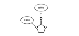
- FIG. 1 shows a model diagram showing the interaction between one molecule of dimethyl carbonate and two molecules of metal salt in the electrolytic solution.
- the unshared electron pair of C ⁇ O oxygen may be present above the molecular center, and the unshared electron pair of O—C oxygen may be present below the molecular center.
- Dimethyl carbonate can be coordinated with one molecule of the metal salt by the unshared electron pair of the upper oxygen, and can be coordinated with another molecule of the metal salt by the unshared electron pair of the lower oxygen.
- two metal salt molecules are separated from each other while maintaining a stable coordination state due to the chemical structure of dimethyl carbonate. It is a difficult state.
- FIG. 2 shows a model diagram showing the interaction between one molecule of ethylene carbonate and two molecules of metal salt in the electrolytic solution.
- a plurality of unshared electron pairs of ethylene carbonate exist in substantially the same direction as viewed from the molecular center of ethylene carbonate. Therefore, as shown in FIG. 2, the metal salts coordinated to ethylene carbonate exist in the vicinity of each other, so that the metal salts can be easily approached.
- a solid solute being dissolved in a solvent means that the intermolecular force between solute molecules is cut and the solute molecules are almost uniformly present in the solvent matrix. And the said state can be suitably maintained because a solvent solvates with a solute molecule.
- a solid that is an aggregate of the solute molecules is generated again, so that the dissolved state is released.
- the specific organic solvent can prevent the metal salt that is a solute from approaching due to the chemical structure of the specific organic solvent. Therefore, it is considered that the electrolytic solution of the present invention can maintain the dissolved state of the metal salt even when the metal salt concentration is higher than usual.
- R 10 , R 11 , R 12 , R 13 , R 14 , R 15 , R 16 are each independently It is preferably selected from C n H a F b which is a chain alkyl, or C m H f F g which contains a cyclic alkyl in the chemical structure.
- n is an integer of 1 or more
- m is an integer of 3 or more
- N in the general formula (1-1), the general formula (1-2), or the general formula (1-3) is preferably an integer of 1 to 6, more preferably an integer of 1 to 4.
- the integer of is particularly preferable.
- m is preferably an integer of 3 to 8, more preferably an integer of 4 to 7, and particularly preferably an integer of 5 to 6.
- a chain carbonate represented by the general formula (1-1) is preferable.
- Examples of the chain carbonate represented by the general formula (1-1) include dimethyl carbonate (hereinafter sometimes referred to as “DMC”), diethyl carbonate (hereinafter sometimes referred to as “DEC”), and ethyl methyl carbonate.
- DMC dimethyl carbonate
- DEC diethyl carbonate
- ethyl methyl carbonate examples include dimethyl carbonate (hereinafter sometimes referred to as “DMC”), diethyl carbonate (hereinafter sometimes referred to as “DEC”), and ethyl methyl carbonate.
- EMC fluoromethyl methyl carbonate, difluoromethyl methyl carbonate, trifluoromethyl methyl carbonate, bis (fluoromethyl) carbonate, bis (difluoro) methyl carbonate, bis (trifluoromethyl) carbonate , Fluoromethyl difluoromethyl carbonate, fluoromethyl trifluoromethyl carbonate, difluoromethyl trifluoromethyl carbonate, 2-fluoroethyl methyl carbonate, 2,2-difluoroethyl methyl -Bonate, 2,2,2-trifluoroethyl methyl carbonate, pentafluoroethyl methyl carbonate, ethyl trifluoromethyl carbonate, fluoroethyl ethyl carbonate, trifluoroethyl ethyl carbonate, bis (2,2,2-trifluoroethyl) carbonate Is particularly preferred.
- ester represented by the general formula (1-2) examples include methyl acetate, ethyl acetate, propyl acetate, butyl acetate, methyl propionate, ethyl propionate, methyl fluoroacetate, ethyl fluoroacetate, methyl difluoroacetate, ethyl difluoroacetate , Methyl trifluoroacetate, ethyl trifluoroacetate, 2-fluoroethyl acetate, 2,2-difluoroethyl acetate, 2,2,2-trifluoroethyl acetate, 2-fluoroethyl fluoroacetate, 2,2-difluorofluoroacetate Ethyl, 2,2,2-trifluoroethyl fluoroacetate, 2-fluoroethyl difluoroacetate, 2,2-difluoroethyl difluoroacetate, 2,2,2-trifluoroethyl
- Examples of the phosphoric acid ester represented by the general formula (1-3) include phosphoric acid trimethyl ester, phosphoric acid ethyl dimethyl ester, phosphoric acid diethyl methyl ester, phosphoric acid triethyl ester, phosphoric acid dimethyl 2-fluoroethyl ester, phosphoric acid Dimethyl 2,2-difluoroethyl ester, phosphoric acid dimethyl 2,2,2-trifluoroethyl ester, phosphoric acid diethyl 2-fluoroethyl ester, phosphoric acid diethyl 2,2-difluoroethyl ester, phosphoric acid diethyl 2,2, 2-trifluoroethyl ester, phosphoric acid methyl bis (2-fluoroethyl) ester, phosphoric acid methyl bis (2,2-difluoroethyl) ester, phosphoric acid methyl bis (2,2,2-trifluoroethyl) ester, phospho
- the chain carbonate represented by the general formula (1-1), the ester represented by the general formula (1-2), and the phosphate ester represented by the general formula (1-3) described above are each independently And may be used in the electrolyte solution, or a plurality of them may be used in combination.
- Examples of the cation of the metal salt in the electrolytic solution of the present invention include alkali metals such as lithium, sodium and potassium, alkaline earth metals such as beryllium, magnesium, calcium, strontium and barium, and aluminum.
- the cation of the metal salt is preferably the same metal ion as the charge carrier of the battery using the electrolytic solution.
- the metal salt cation is preferably lithium.
- the metal salt of the present invention may be a combination of an appropriate number of cations and anions described above.
- One kind of metal salt in the electrolytic solution of the present invention may be used, or a plurality of kinds may be used in combination.
- the electrolyte solution of the present invention may contain other electrolytes that can be used for the electrolyte solution of the power storage device in addition to the metal salt.
- the metal salt is preferably contained in an amount of 50% by mass or more, more preferably 70% by mass or more, based on the total electrolyte contained in the electrolytic solution of the present invention, and 90% by mass. More preferably, it is contained in% or more.
- the metal salt is preferably contained in an amount of 50 mol% or more, more preferably 70 mol% or more, based on the total electrolyte contained in the electrolytic solution of the present invention. More preferably, it is contained at 90 mol% or more.
- the specific organic solvent is contained in a molar ratio of 1 to 8 with respect to the metal salt. If the molar ratio is less than 1, the density and viscosity of the electrolytic solution become too high, and the ionic conductivity of the electrolytic solution may be significantly reduced. If the molar ratio exceeds 8, the number of ions that can participate in ionic conduction decreases, and the ionic conductivity of the electrolyte may decrease, or when charging / discharging with a large current, Li to the electrode through the electrolyte There is a risk that the amount of ion supply will be insufficient and resistance (diffusion resistance) will increase.
- the low temperature solidification property is deteriorated and the corrosivity of the aluminum current collector is deteriorated when the power storage device including the electrolytic solution is driven at a high potential.
- the range of the molar ratio in the electrolytic solution of the present invention 1 to 5, 1 to 4, 1 to 3, 1 to 6, 2 to 6, 2 to 5, 2 to 4, 2 to 3, 3 to 5, 3 ⁇ 4 can be exemplified.
- the conventional electrolytic solution has a molar ratio of the organic solvent to the metal salt of about 10.
- the molar ratio can vary within a suitable range depending on the type of metal salt.
- the molar ratio is preferably in the range of 4-8, more preferably in the range of 5-7, A range of 5 to 6 is more preferable.
- the chemical structure of the metal salt anion is BX 4
- the molar ratio is preferably in the range of 2-6, more preferably in the range of 3-5, and further in the range of 3-4. Is preferred.
- the electrolytic solution of the present invention has a peak obtained by shifting the peak of the specific organic solvent to Io with respect to the peak intensity derived from the specific organic solvent in the vibrational spectrum (hereinafter referred to as “shift peak”). In some cases, Is> 0.8 ⁇ Io is observed. A preferable electrolyte solution of the present invention satisfies Is> Io.
- original peak of a specific organic solvent means a peak observed at a peak position (wave number) when only a specific organic solvent is measured by vibrational spectroscopy.
- the value of the peak intensity Io inherent in the organic solvent and the value of the shift peak intensity Is are the height or area from the baseline of each peak in the vibrational spectrum.
- the peak derived from the specific organic solvent forming the cluster is based on the observed wave number of the peak derived from the specific organic solvent not participating in the cluster formation (that is, the original peak of the specific organic solvent). It is observed by shifting to the high wave number side or the low wave number side.
- the relationship when there are a plurality of shift peaks, the relationship may be determined based on the peak for which the relationship between Is and Io is most easily determined. Further, when a plurality of specific organic solvents are used in the electrolytic solution of the present invention, an organic solvent in which the relationship between Is and Io is most easily determined (the difference between Is and Io is most obvious) is selected, and its peak intensity Based on the above, the relationship between Is and Io may be determined. If the peak shift amount is small and the peaks before and after the shift appear to be a gentle mountain, peak separation may be performed using known means to determine the relationship between Is and Io.
- vibrational spectrum examples include an IR spectrum and a Raman spectrum.
- IR spectrum measurement methods include transmission measurement methods such as Nujol method and liquid film method, and reflection measurement methods such as ATR method.
- ATR method reflection measurement methods
- a spectrum in which the relationship between Is and Io can be easily determined in the vibrational spectrum of the electrolytic solution of the present invention may be selected.
- the vibrational spectroscopic measurement is preferably performed under conditions that can reduce or ignore the influence of moisture in the atmosphere. For example, IR measurement may be performed under low humidity or no humidity conditions such as a dry room or a glove box, or Raman measurement may be performed with the electrolyte solution in a sealed container.
- vibrational spectral spectrum chart obtained by subjecting the electrolytic solution of the present invention to vibrational spectroscopic measurement, it is sometimes observed that the peak derived from the chemical structure of the anion of the metal salt shifts to the low wavenumber side or the high wavenumber side. is there.
- vibrational spectrum include an IR spectrum and a Raman spectrum.
- the electrolytic solution of the present invention contains a metal salt at a high concentration, the cation and the anion constituting the metal salt interact strongly, and the metal salt mainly has a CIP (Contact ion pairs) state or an AGG (aggregate) state. It is inferred that it has formed. And the change of this state is observed as a peak shift derived from the chemical structure of the anion of the metal salt in the vibrational spectroscopic spectrum chart.
- the electrolytic solution of the present invention has a higher proportion of metal salt than the conventional electrolytic solution. If it does so, it can be said that the electrolyte solution of this invention differs in the presence environment of a metal salt and an organic solvent compared with the conventional electrolyte solution.
- an improvement in the transport rate of metal ions in the electrolytic solution an improvement in the reaction rate at the interface between the electrode and the electrolytic solution, a high rate charge / discharge of the secondary battery It can be expected to alleviate the uneven distribution of metal salt concentration in the electrolyte, improve the electrolyte retention at the electrode interface, suppress the so-called drainage state where the electrolyte is insufficient at the electrode interface, and increase the capacity of the electric double layer.
- the vapor pressure of the organic solvent contained in the electrolytic solution is lowered. As a result, volatilization of the organic solvent from the electrolytic solution of the present invention can be reduced.
- the electrolytic solution of the present invention contains a high concentration of metal salt cations. For this reason, in the electrolytic solution of the present invention, the distance between adjacent cations is extremely short. When a cation such as lithium ion moves between the positive electrode and the negative electrode during charge / discharge of the secondary battery, the cation closest to the destination electrode is first supplied to the electrode. And the other cation adjacent to the said cation moves to the place with the said supplied cation. In other words, in the electrolytic solution of the present invention, it is expected that a domino-like phenomenon occurs in which adjacent cations change one by one toward the electrode to be supplied one by one.
- the electrolytic solution of the present invention has ionic conductivity even if it has a high viscosity.
- nitriles such as acetonitrile (hereinafter sometimes referred to as “AN”), propionitrile, acrylonitrile, malononitrile, 1,2-dimethoxyethane (hereinafter referred to as “DME”).
- AN acetonitrile
- DME 1,2-dimethoxyethane
- the chain carbonate represented by the general formula (1-1), the ester represented by the general formula (1-2), or the total solvent contained in the electrolytic solution of the present invention is preferably contained in, for example, 70% by volume or more, 80% by volume or more, 90% by volume or more, or 95% by volume or more.
- the electrolytic solution of the present invention includes a chain carbonate represented by the general formula (1-1) and an ester represented by the general formula (1-2) with respect to all the solvents contained in the electrolytic solution of the present invention.
- the phosphate ester represented by the general formula (1-3) is contained, for example, in an amount of 70 mol% or more, 80 mol% or more, 90 mol% or more, or 95 mol% or more.
- organic solvent composed of the hydrocarbon examples include benzene, toluene, ethylbenzene, o-xylene, m-xylene, p-xylene, 1-methylnaphthalene, hexane, heptane, and cyclohexane.
- a flame retardant solvent can be added to the electrolytic solution of the present invention.
- a flame retardant solvent include halogen solvents such as carbon tetrachloride, tetrachloroethane, and hydrofluoroether.
- the mixture contains the electrolyte solution and becomes a pseudo solid electrolyte.
- the pseudo-solid electrolyte as the battery electrolyte, leakage of the electrolyte in the battery can be suppressed.
- a polymer used for a battery such as a lithium ion secondary battery or a general chemically crosslinked polymer can be employed.
- a polymer that can absorb an electrolyte such as polyvinylidene fluoride and polyhexafluoropropylene and gel can be used, and a polymer such as polyethylene oxide in which an ion conductive group is introduced.
- polymers include polymethyl acrylate, polymethyl methacrylate, polyethylene oxide, polypropylene oxide, polyacrylonitrile, polyvinylidene fluoride, polyethylene glycol dimethacrylate, polyethylene glycol acrylate, polyglycidol, polytetrafluoroethylene, polyhexafluoropropylene, Polycarboxylic acid such as polysiloxane, polyvinyl acetate, polyvinyl alcohol, polyacrylic acid, polymethacrylic acid, polyitaconic acid, polyfumaric acid, polycrotonic acid, polyangelic acid, carboxymethylcellulose, styrene-butadiene rubber, nitrile-butadiene rubber, polystyrene , Polycarbonate, unsaturated polyester copolymerized with maleic anhydride and glycols, Polyethylene oxide derivative having a group, a copolymer of vinylidene fluoride and hexafluoropropylene can be exempl
- Polysaccharides are also suitable as the polymer.
- Specific examples of the polysaccharide include glycogen, cellulose, chitin, agarose, carrageenan, heparin, hyaluronic acid, pectin, amylopectin, xyloglucan, and amylose.
- adopt the material containing these polysaccharides as said polymer The agar containing polysaccharides, such as agarose, can be illustrated as the said material.
- the inorganic filler is preferably an inorganic ceramic such as oxide or nitride.
- Inorganic ceramics have hydrophilic and hydrophobic functional groups on the surface. Therefore, when the functional group attracts the electrolytic solution, a conductive path can be formed in the inorganic ceramic. Furthermore, the inorganic ceramics dispersed in the electrolytic solution can form a network between the inorganic ceramics by the functional groups and serve to contain the electrolytic solution. With such a function of the inorganic ceramics, it is possible to more suitably suppress the leakage of the electrolytic solution in the battery. In order to suitably exhibit the above functions of the inorganic ceramics, the inorganic ceramics preferably have a particle shape, and particularly preferably have a particle size of nano level.
- the inorganic ceramics include general alumina, silica, titania, zirconia, and lithium phosphate. Further, the inorganic ceramic itself may be lithium conductive, and specifically, Li 3 N, LiI, LiI—Li 3 N—LiOH, LiI—Li 2 S—P 2 O 5 , LiI—Li 2 S —P 2 S 5 , LiI—Li 2 S—B 2 S 3 , Li 2 O—B 2 S 3 , Li 2 O—V 2 O 3 —SiO 2 , Li 2 O—B 2 O 3 —P 2 O 5 , Li 2 O—B 2 O 3 —ZnO, Li 2 O—Al 2 O 3 —TiO 2 —SiO 2 —P 2 O 5 , LiTi 2 (PO 4 ) 3 , Li— ⁇ Al 2 O 3 , LiTaO 3 Can be illustrated.
- Li 3 N LiI, LiI—Li 3 N—LiOH, LiI—Li 2 S—
- Glass ceramics may be employed as the inorganic filler. Since glass ceramics can contain an ionic liquid, the same effect can be expected for the electrolytic solution of the present invention. Glass ceramics include a compound represented by xLi 2 S- (1-x) P 2 S 5 , a compound obtained by substituting a part of S of the compound with another element, and a P of the compound. An example in which the part is replaced with germanium can be exemplified.
- a known additive may be added to the electrolytic solution of the present invention without departing from the spirit of the present invention.
- known additives include cyclic carbonates having unsaturated bonds typified by vinylene carbonate (VC), vinyl ethylene carbonate (VEC), methyl vinylene carbonate (MVC), and ethyl vinylene carbonate (EVC); fluoroethylene carbonate, Carbonate compounds represented by trifluoropropylene carbonate, phenylethylene carbonate and erythritan carbonate; succinic anhydride, glutaric anhydride, maleic anhydride, citraconic anhydride, glutaconic anhydride, itaconic anhydride, diglycolic anhydride, cyclohexanedicarboxylic acid Carboxylic anhydrides represented by acid anhydrides, cyclopentanetetracarboxylic dianhydrides, phenylsuccinic anhydrides; ⁇ -butyrolactone, ⁇ -valerolactone
- the method for producing the electrolytic solution of the present invention will be described. Since the electrolytic solution of the present invention has a higher metal salt content than the conventional electrolytic solution, the production method of adding a specific organic solvent to a solid (powder) metal salt results in the formation of an aggregate, resulting in a solution state It may be difficult to produce the electrolyte solution. Therefore, in the method for producing an electrolytic solution of the present invention, it is preferable to produce the electrolytic solution while gradually adding a metal salt to the specific organic solvent and maintaining the solution state of the electrolytic solution.
- a predetermined amount of a specific organic solvent and a metal salt are mixed in advance, under ultrasonic vibration, high-speed stirring, stirring with a strong shear force, and / or under heating such as reflux conditions of the specific organic solvent.
- the dissolution of the metal salt may be completed to produce the electrolytic solution of the present invention.
- the electrolytic solution of the present invention described above is preferably used as an electrolytic solution for a power storage device such as a battery.
- a power storage device such as a battery.
- it is preferably used as an electrolytic solution for a capacitor or a secondary battery, and particularly preferably used as an electrolytic solution for a lithium ion secondary battery, an electric double layer capacitor, or a lithium ion capacitor.
- the secondary battery including the electrolytic solution of the present invention is referred to as “secondary battery of the present invention”
- the lithium ion secondary battery including the electrolytic solution of the present invention is referred to as “lithium ion secondary battery of the present invention”.
- a capacitor including the electrolytic solution of the present invention is sometimes referred to as “capacitor of the present invention”.
- lithium ion secondary battery of the present invention comprising the above-described electrolytic solution of the present invention will be described.
- the lithium ion secondary battery of the present invention employs a negative electrode having a negative electrode active material capable of occluding and releasing lithium ions, a positive electrode having a positive electrode active material capable of occluding and releasing lithium ions, and a lithium salt as a metal salt.
- the electrolytic solution of the present invention is provided.
- the negative electrode active material a material capable of inserting and extracting lithium ions can be used. Accordingly, there is no particular limitation as long as it is a simple substance, alloy, or compound that can occlude and release lithium ions.
- a negative electrode active material Li, group 14 elements such as carbon, silicon, germanium and tin, group 13 elements such as aluminum and indium, group 12 elements such as zinc and cadmium, group 15 elements such as antimony and bismuth, magnesium , Alkaline earth metals such as calcium, and group 11 elements such as silver and gold may be employed alone.
- silicon or the like is used for the negative electrode active material, a silicon atom reacts with a plurality of lithiums, so that it becomes a high-capacity active material.
- the alloy or compound include tin-based materials such as Ag—Sn alloy, Cu—Sn alloy and Co—Sn alloy, carbon-based materials such as various graphites, SiO x (disproportionated into silicon simple substance and silicon dioxide). Examples thereof include silicon-based materials such as 0.3 ⁇ x ⁇ 1.6), silicon alone, or composites obtained by combining silicon-based materials and carbon-based materials.
- graphite having a G / D ratio of 3.5 or more can be exemplified.
- the G / D ratio is a ratio of G-band and D-band peaks in a Raman spectrum.
- G-band 'is in the vicinity of 1590cm -1 D-band is observed as each peak around 1350 cm -1.
- G-band is derived from a graphite structure, and D-band is derived from a defect. Therefore, the higher the G / D ratio, which is the ratio of G-band to D-band, means that the graphite has fewer defects and higher crystallinity.
- graphite having a G / D ratio of 3.5 or more may be referred to as high crystalline graphite
- graphite having a G / D ratio of less than 3.5 may be referred to as low crystalline graphite.
- the highly crystalline graphite either natural graphite or artificial graphite can be adopted.
- scaly graphite, spherical graphite, massive graphite, earthy graphite, etc. can be adopted.
- coated graphite whose surface is coated with a carbon material or the like can be employed.
- a carbon material having a crystallite size of 20 nm or less, preferably 5 nm or less can be exemplified.
- a larger crystallite size means a carbon material in which atoms are arranged periodically and accurately according to a certain rule.
- a carbon material having a crystallite size of 20 nm or less is in a state of poor atomic periodicity and alignment accuracy.
- the carbon material is graphite
- the size of the graphite crystal is 20 nm or less, or due to the influence of strain, defects, impurities, etc., the regularity of the arrangement of the atoms constituting the graphite becomes poor.
- the size is 20 nm or less.
- Typical carbon materials having a crystallite size of 20 nm or less are non-graphitizable carbon, so-called hard carbon, graphitizable carbon, so-called soft carbon.
- an X-ray diffraction method using CuK ⁇ rays as an X-ray source may be used.
- L 0.94 ⁇ / ( ⁇ cos ⁇ ) here, L: Crystallite size ⁇ : Incident X-ray wavelength (1.54 mm) ⁇ : half width of peak (radian) ⁇ : Diffraction angle
- a material containing silicon can be exemplified. More specifically, SiO x (0.3 ⁇ x ⁇ 1.6) disproportionated into two phases of Si phase and silicon oxide phase can be exemplified. The Si phase in SiO x can occlude and release lithium ions, and changes in volume as the secondary battery is charged and discharged. The silicon oxide phase has less volume change associated with charge / discharge than the Si phase. That is, SiO x as the negative electrode active material realizes a high capacity by the Si phase and suppresses the volume change of the entire negative electrode active material by having the silicon oxide phase.
- the range of x is more preferably 0.5 ⁇ x ⁇ 1.5, and further preferably 0.7 ⁇ x ⁇ 1.2.
- SiO x as described above, it is believed to alloying reaction with the silicon lithium and Si phase during charging and discharging of the lithium ion secondary battery may occur. And it is thought that this alloying reaction contributes to charging / discharging of a lithium ion secondary battery.
- a negative electrode active material containing tin described later can be charged and discharged by an alloying reaction between tin and lithium.
- a material containing tin can be exemplified. More specifically, examples include Sn alone, tin alloys such as Cu—Sn and Co—Sn, amorphous tin oxide, and tin silicon oxide. SnB 0.4 P 0.6 O 3.1 can be exemplified as the amorphous tin oxide, and SnSiO 3 can be exemplified as the tin silicon oxide.
- the material containing silicon and the material containing tin are combined with a carbon material to form a negative electrode active material. Due to the composite, the structure of silicon and / or tin is particularly stabilized, and the durability of the negative electrode is improved.
- the above compounding may be performed by a known method.
- the carbon material used for the composite graphite, hard carbon, soft carbon or the like may be employed.
- the graphite may be natural graphite or artificial graphite.
- lithium titanate having a spinel structure such as Li 4 + x Ti 5 + y O 12 (-1 ⁇ x ⁇ 4, ⁇ 1 ⁇ y ⁇ 1)), or a ramsdellite structure such as Li 2 Ti 3 O 7
- the lithium titanate can be illustrated.
- the negative electrode active material include graphite having a major axis / minor axis value of 1 to 5, preferably 1 to 3.
- the long axis means the length of the longest portion of the graphite particles.
- the short axis means the length of the longest portion in the direction orthogonal to the long axis.
- the graphite corresponds to spherical graphite or mesocarbon microbeads.
- Spherical graphite is a carbon material such as artificial graphite, natural graphite, graphitizable carbon, and non-graphitizable carbon, and has a spherical shape or a substantially spherical shape.
- Spherical graphite is obtained by pulverizing graphite with an impact pulverizer having a relatively small crushing force to obtain flakes, and then compressing the flakes into a compression spheroid.
- the impact pulverizer include a hammer mill and a pin mill. It is preferable to carry out the above operation by setting the peripheral linear velocity of the hammer or pin of the mill to about 50 to 200 m / second. It is preferable that graphite is supplied to and discharged from the mill while being accompanied by an air current such as air.
- the graphite preferably has a BET specific surface area in the range of 0.5 to 15 m 2 / g. If the BET specific surface area is too large, the side reaction between the graphite and the electrolyte solution may be accelerated, and if the BET specific surface area is too small, the reaction resistance of the graphite may be increased.
- the negative electrode has a current collector and a negative electrode active material layer bound to the surface of the current collector.
- a current collector refers to a chemically inert electronic high conductor that keeps a current flowing through an electrode during discharge or charging of a lithium ion secondary battery.
- the current collector at least one selected from silver, copper, gold, aluminum, tungsten, cobalt, zinc, nickel, iron, platinum, tin, indium, titanium, ruthenium, tantalum, chromium, molybdenum, and stainless steel, etc. Metal materials can be exemplified.
- the current collector may be covered with a known protective layer. What collected the surface of the electrical power collector by the well-known method may be used as an electrical power collector.
- the current collector can take the form of a foil, a sheet, a film, a linear shape, a rod shape, a mesh, or the like. Therefore, for example, a metal foil such as a copper foil, a nickel foil, an aluminum foil, and a stainless steel foil can be suitably used as the current collector.
- a metal foil such as a copper foil, a nickel foil, an aluminum foil, and a stainless steel foil can be suitably used as the current collector.
- the thickness is preferably in the range of 1 ⁇ m to 100 ⁇ m.
- the negative electrode active material layer contains a negative electrode active material and, if necessary, a binder and / or a conductive aid.
- the binder plays a role of connecting the active material and the conductive auxiliary agent to the surface of the current collector.
- Binders include fluorine-containing resins such as polyvinylidene fluoride, polytetrafluoroethylene, and fluororubber, thermoplastic resins such as polypropylene and polyethylene, imide resins such as polyimide and polyamideimide, alkoxysilyl group-containing resins, and styrene butadiene. What is necessary is just to employ
- a polymer having a hydrophilic group may be employed as the binder.
- the hydrophilic group of the polymer having a hydrophilic group include a phosphate group such as a carboxyl group, a sulfo group, a silanol group, an amino group, a hydroxyl group, and a phosphate group.
- a polymer containing a carboxyl group in a molecule such as polyacrylic acid, carboxymethylcellulose, or polymethacrylic acid, or a polymer containing a sulfo group such as poly (p-styrenesulfonic acid) is preferable.
- Polymers containing a large amount of carboxyl groups and / or sulfo groups such as polyacrylic acid or a copolymer of acrylic acid and vinyl sulfonic acid, are water-soluble.
- the polymer having a hydrophilic group is preferably a water-soluble polymer, and in terms of chemical structure, a polymer containing a plurality of carboxyl groups and / or sulfo groups in one molecule is preferable.
- the polymer containing a carboxyl group in the molecule can be produced by, for example, a method of polymerizing an acid monomer or a method of imparting a carboxyl group to the polymer.
- Acid monomers include acrylic acid, methacrylic acid, vinyl benzoic acid, crotonic acid, pentenoic acid, angelic acid, tiglic acid, etc., acid monomers having one carboxyl group in the molecule, itaconic acid, mesaconic acid, citraconic acid, fumaric acid
- Examples include maleic acid, 2-pentenedioic acid, methylene succinic acid, allyl malonic acid, isopropylidene succinic acid, 2,4-hexadiene diacid, acetylenedicarboxylic acid, and other acid monomers having two or more carboxyl groups in the molecule. Is done.
- a copolymer obtained by polymerizing two or more acid monomers selected from the above acid monomers may be used as a binder.
- a polymer containing in its molecule an acid anhydride group formed by condensation of carboxyl groups of a copolymer of acrylic acid and itaconic acid as described in JP2013-065493A It is also preferable to use as a binder.
- the binder has a structure derived from a highly acidic monomer having two or more carboxyl groups in one molecule, it becomes easier for the binder to trap lithium ions etc. before the electrolyte decomposition reaction occurs during charging. It is considered.
- the polymer has more carboxyl groups per monomer than polyacrylic acid or polymethacrylic acid, the acidity is increased, but since the predetermined amount of carboxyl groups is changed to acid anhydride groups, the acidity is increased. Is not too high. Therefore, a secondary battery having a negative electrode using the polymer as a binder has improved initial efficiency and improved input / output characteristics.
- Conductive aid is added to increase the conductivity of the electrode. Therefore, the conductive auxiliary agent may be added arbitrarily when the electrode conductivity is insufficient, and may not be added when the electrode conductivity is sufficiently excellent.
- the conductive auxiliary agent may be any chemically inert electronic high conductor, such as carbon black, graphite, acetylene black, ketjen black (registered trademark), or vapor grown carbon fiber (Vapor Grown Carbon). Fiber: VGCF) and various metal particles are exemplified. These conductive assistants can be added to the active material layer alone or in combination of two or more.
- the positive electrode used for the lithium ion secondary battery has a positive electrode active material capable of inserting and extracting lithium ions.
- the positive electrode has a current collector and a positive electrode active material layer bound to the surface of the current collector.
- the positive electrode active material layer includes a positive electrode active material and, if necessary, a binder and / or a conductive aid.
- the positive electrode current collector is not particularly limited as long as it is a metal that can withstand a voltage suitable for the active material to be used. For example, silver, copper, gold, aluminum, tungsten, cobalt, zinc, nickel, iron, platinum, tin , Indium, titanium, ruthenium, tantalum, chromium, molybdenum, and metal materials such as stainless steel.
- the potential of the positive electrode is 4 V or higher with respect to lithium, it is preferable to employ aluminum as the current collector.
- aluminum refers to pure aluminum, and aluminum having a purity of 99.0% or more is referred to as pure aluminum.
- An alloy obtained by adding various elements to pure aluminum is referred to as an aluminum alloy. Examples of the aluminum alloy include Al—Cu, Al—Mn, Al—Fe, Al—Si, Al—Mg, AL—Mg—Si, and Al—Zn—Mg.
- aluminum or aluminum alloy examples include, for example, A1000 series alloys (pure aluminum series) such as JIS A1085 and A1N30, A3000 series alloys (Al-Mn series) such as JIS A3003 and A3004, JIS A8079, A8021, etc. A8000-based alloy (Al-Fe-based).
- the current collector may be covered with a known protective layer. What collected the surface of the electrical power collector by the well-known method may be used as an electrical power collector.
- the current collector can take the form of a foil, a sheet, a film, a linear shape, a rod shape, a mesh, or the like. Therefore, for example, a metal foil such as a copper foil, a nickel foil, an aluminum foil, and a stainless steel foil can be suitably used as the current collector.
- a metal foil such as a copper foil, a nickel foil, an aluminum foil, and a stainless steel foil can be suitably used as the current collector.
- the thickness is preferably in the range of 1 ⁇ m to 100 ⁇ m.
- a metal oxide having a spinel structure such as LiMn 2 O 4 and a solid solution composed of a mixture of a metal oxide having a spinel structure and a layered compound, LiMPO 4 , LiMVO 4, or Li 2 MSiO 4 (formula M in the middle is selected from at least one of Co, Ni, Mn, and Fe).
- tavorite compound (the M a transition metal) LiMPO 4 F such as LiFePO 4 F represented by, Limbo 3 such LiFeBO 3 (M is a transition metal
- LiMPO 4 F such as LiFePO 4 F represented by, Limbo 3 such LiFeBO 3 (M is a transition metal
- any metal oxide used as the positive electrode active material may have the above composition formula as a basic composition, and a metal element contained in the basic composition may be substituted with another metal element.
- a charge carrier for example, lithium ion which contributes to charging / discharging.
- sulfur alone, compounds in which sulfur and carbon are compounded, metal sulfides such as TiS 2 , oxides such as V 2 O 5 and MnO 2 , compounds containing polyaniline and anthraquinone, and aromatics in their chemical structures, conjugated two Conjugated materials such as acetic acid organic materials and other known materials can also be used.
- a compound having a stable radical such as nitroxide, nitronyl nitroxide, galvinoxyl, phenoxyl, etc. may be adopted as the positive electrode active material.
- a positive electrode active material that does not contain a charge carrier such as lithium it is necessary to add a charge carrier to the positive electrode and / or the negative electrode in advance by a known method.
- the charge carrier may be added in an ionic state or in a non-ionic state such as a metal.
- the charge carrier when the charge carrier is lithium, it may be integrated by attaching a lithium foil to the positive electrode and / or the negative electrode.
- Li x A y Mn 2- y O 4 (A spinel structure, Ca, Mg, S, Si , Na, K, Al, P, Ga, at least one selected from Ge And at least one metal element selected from an element and / or a transition metal element, for example, 0 ⁇ x ⁇ 2.2, 0 ⁇ y ⁇ 1). More specifically, LiMn 2 O 4 and LiNi 0.5 Mn 1.5 O 4 can be exemplified.
- 0.7 ⁇ a ⁇ 1.2 and 0.9 ⁇ a ⁇ 1.1 can be exemplified as a suitable range of a, and 0.1 ⁇ b ⁇ 0.6, 0,.
- 2 ⁇ b ⁇ 0.55 can be exemplified, and 0.1 ⁇ c ⁇ 0.8 and 0.2 ⁇ c ⁇ 0.55 can be exemplified as preferable ranges of c, and 0.01 ⁇ d ⁇ 0.5, 0.1 ⁇ d ⁇ 0.4 can be exemplified, and the preferred range of e can be exemplified by 0 ⁇ e ⁇ 0.3, 0 ⁇ e ⁇ 0.1, and the preferred range of f For example, 1.8 ⁇ c ⁇ 2.05.
- More specific layered rock salt structure compounds include LiNi 0.5 Co 0.3 Mn 0.2 O 2 , LiNi 0.5 Co 0.2 Mn 0.3 O 2 , LiNi 1/3 Co 1/3 Mn Examples thereof include 1/3 O 2 , LiNi 0.5 Mn 0.5 O 2 , LiNi 0.75 Co 0.1 Mn 0.15 O 2 , LiMnO 2 , LiNiO 2 , and LiCoO 2 .
- Li 2 MnO 3 —LiCoO 2 can be exemplified.
- the positive electrode active material include LiFePO 4 , Li 2 FeSiO 4 , LiCoPO 4 , Li 2 CoPO 4 , Li 2 MnPO 4 , Li 2 MnSiO 4 , and Li 2 CoPO 4 F.
- reaction potential refers to a potential at which the positive electrode active material undergoes an oxidation-reduction reaction by charging and discharging. This reaction potential is based on the Li + / Li electrode. Although the reaction potential may vary somewhat, in this specification, “reaction potential” refers to an average value of reaction potentials having a width. When there are a plurality of reaction potentials, it means an average value among the reaction potentials of the plurality of stages.
- Examples of the positive electrode active material having a reaction potential of 4.5 V or more on the basis of the Li + / Li electrode include Li x A y Mn 2 which is a metal oxide having a spinel structure such as LiNi 0.5 Mn 1.5 O 4.
- -y O 4 (A is at least one metal element selected from Ca, Mg, S, Si, Na, K, Al, P, Ga, Ge and / or transition metal elements. 0 ⁇ x ⁇ 2.2, 0 ⁇ y ⁇ 1), LiCoPO 4 , Li 2 CoPO 4 F, Li 2 MnO 3 —LiMO 2 (wherein M is at least one of Co, Ni, Mn, and Fe) Li 2 MnSiO 4 or the like.
- a current collecting method such as a roll coating method, a die coating method, a dip coating method, a doctor blade method, a spray coating method, or a curtain coating method can be used.
- An active material may be applied to the surface of the body.
- an active material layer-forming composition containing an active material and, if necessary, a binder and a conductive aid is prepared, and an appropriate solvent is added to the composition to make a paste, and then the collection is performed. After applying to the surface of the electric body, it is dried.
- the solvent include N-methyl-2-pyrrolidone, methanol, methyl isobutyl ketone, and water.
- the dried product may be compressed.
- a separator is used for a lithium ion secondary battery as required.
- the separator separates the positive electrode and the negative electrode and allows lithium ions to pass while preventing a short circuit due to contact between the two electrodes.
- a known separator may be employed, such as polytetrafluoroethylene, polypropylene, polyethylene, polyimide, polyamide, polyaramid (Aromatic polyamide), polyester, polyacrylonitrile, or other synthetic resin, cellulose, amylose, or other polysaccharides, fibroin. And porous materials, nonwoven fabrics, woven fabrics, and the like using one or more electrical insulating materials such as natural polymers such as keratin, lignin, and suberin, and ceramics.
- the separator may have a multilayer structure.
- a specific method for producing the lithium ion secondary battery of the present invention will be described. If necessary, a separator is sandwiched between the positive electrode and the negative electrode to form an electrode body.
- the electrode body may be either a stacked type in which the positive electrode, the separator and the negative electrode are stacked, or a wound type in which the positive electrode, the separator and the negative electrode are sandwiched.
- the electrolyte solution of the present invention is added to the electrode body and lithium ions are added.
- a secondary battery may be used.
- the lithium ion secondary battery of this invention should just be charged / discharged in the voltage range suitable for the kind of active material contained in an electrode.
- the shape of the lithium ion secondary battery of the present invention is not particularly limited, and various shapes such as a cylindrical shape, a square shape, a coin shape, and a laminate shape can be adopted.
- the lithium ion secondary battery of the present invention may be mounted on a vehicle.
- the vehicle may be a vehicle that uses electric energy generated by a lithium ion secondary battery for all or a part of its power source.
- the vehicle may be an electric vehicle or a hybrid vehicle.
- a lithium ion secondary battery is mounted on a vehicle, a plurality of lithium ion secondary batteries may be connected in series to form an assembled battery.
- devices equipped with lithium ion secondary batteries include various home appliances driven by batteries such as personal computers and portable communication devices, office devices, and industrial devices in addition to vehicles.
- the lithium ion secondary battery of the present invention includes wind power generation, solar power generation, hydroelectric power generation and other power system power storage devices and power smoothing devices, power supplies for ships and / or auxiliary power supply sources, aircraft, Power supply for spacecraft and / or auxiliary equipment, auxiliary power supply for vehicles that do not use electricity as a power source, power supply for mobile home robots, power supply for system backup, power supply for uninterruptible power supply, You may use for the electrical storage apparatus which stores temporarily the electric power required for charge in the charging station for electric vehicles.
- the lithium ion secondary battery of the present invention part or all of the negative electrode active material or the positive electrode active material, or part or all of the negative electrode active material and the positive electrode active material is used as the polarizable electrode material.
- the capacitor of the present invention may be replaced with activated carbon or the like.
- Examples of the capacitor of the present invention include an electric double layer capacitor and a hybrid capacitor such as a lithium ion capacitor.
- “lithium ion secondary battery” in the description of the lithium ion secondary battery of the present invention described above may be appropriately read as “capacitor”.
- Example 1-1 About 5 mL of DMC, which is a chain carbonate represented by the general formula (1-1), was placed in a flask equipped with a stir bar. Under stirring conditions, LiPF 6 which is a metal salt was gradually added and dissolved in DMC in the flask. LiPF 6 was added in a total amount of 10.01 g, and DMC was further added and stirred so that the total amount of DMC was 11.50 g. Since a little undissolved LiPF 6 was visually recognized, DPF was added to dissolve LiPF 6 so that the total amount of DMC was 11.87 g. This solution was used as the electrolytic solution of Example 1-1. The production was performed in a glove box under an inert gas atmosphere. The concentration of LiPF 6 in the electrolyte solution of Example 1-1 was 4.4 mol / L. In the electrolyte solution of Example 1-1, 2 mol of DMC is contained with respect to 1 mol of LiPF 6 .
- Example 1-2 About 5 mL of DMC, which is a chain carbonate represented by the general formula (1-1), was placed in a flask equipped with a stir bar. Under stirring conditions, LiPF 6 which is a metal salt was gradually added and dissolved in DMC in the flask. It was added 8.02g of LiPF 6 in a total volume, yet the total amount of DMC was dissolved LiPF 6 by adding DMC so that 11.89 g. This solution was used as the electrolytic solution of Example 1-2. The production was performed in a glove box under an inert gas atmosphere. The concentration of LiPF 6 in the electrolytic solution of Example 1-2 was 3.75 mol / L. In the electrolytic solution of Example 1-2, 2.5 mol of DMC is contained with respect to 1 mol of LiPF 6 .
- DMC which is a chain carbonate represented by the general formula (1-1
- Example 1-3 An electrolytic solution of Example 1-3 was produced in the same manner as in Example 1-2, except that 6.99 g of LiPF 6 was used in total and 12.43 g of DMC was used in total.
- the concentration of LiPF 6 in the electrolytic solution of Example 1-3 was 3.19 mol / L.
- 3 mol of DMC is contained per 1 mol of LiPF 6 .
- Example 1-4 8.02 mL of the electrolyte solution of Example 1-2 was transferred to a 10 mL volumetric flask, and DMC was added to make the volume of the solution 10 mL. This was used as the electrolytic solution of Example 1-4. The production was performed in a glove box under an inert gas atmosphere. The concentration of LiPF 6 in the electrolyte solution of Example 1-4 was 3 mol / L. In the electrolyte solution of Example 1-4, 3.31 mol of DMC is contained with respect to 1 mol of LiPF 6 .
- Example 1-5 The electrolytic solution of Example 1-5 was produced in the same manner as in Example 1-4, except that 6.67 mL of the electrolytic solution of Example 1-4 was used.
- the concentration of LiPF 6 in the electrolyte solution of Example 1-5 was 2 mol / L.
- 5.31 mol of DMC was contained with respect to 1 mol of LiPF 6 .
- Example 1-6 The electrolytic solution of Example 1-6 was produced in the same manner as in Example 1-5, except that vinylene carbonate was added so as to be 0.2% by mass with respect to the entire electrolytic solution.
- the concentration of LiPF 6 in the electrolyte solution of Example 1-6 was 2 mol / L.
- Example 2-1 About 5 mL of EMC, which is a chain carbonate represented by the general formula (1-1), was put in a flask equipped with a stirring bar. Under stirring conditions, LiPF 6 which is a metal salt was gradually added to EMC in the flask and dissolved. 8.01 g of LiPF 6 was added in total, and EMC was further added so that the total amount of EMC was 10.98 g, followed by stirring. Since a little undissolved LiPF 6 was visually recognized, EMC was added to dissolve LiPF 6 so that the total amount of EMC was 11.78 g. This solution was used as the electrolyte of Example 2-1. The production was performed in a glove box under an inert gas atmosphere. The concentration of LiPF 6 in the electrolytic solution of Example 2-1 was 3.58 mol / L. In the electrolyte solution of Example 2-1, 2.15 mol of EMC was contained with respect to 1 mol of LiPF 6 .
- Example 3-1 About 5 mL of DEC, which is a chain carbonate represented by the general formula (1-1), was placed in a flask equipped with a stir bar. Under stirring conditions, LiPF 6 which is a metal salt was gradually added to DEC in the flask and dissolved. 8.01 g of LiPF 6 was added in total, and DEC was added so that the total amount of EMC was 12.46 g, followed by stirring. Since a little undissolved LiPF 6 was visually recognized, DEC was added to dissolve LiPF 6 so that the total amount of DEC was 16.72 g. This solution was used as the electrolyte of Example 3-1. The production was performed in a glove box under an inert gas atmosphere. The concentration of LiPF 6 in the electrolyte solution of Example 3-1 was 2.62 mol / L. In the electrolyte solution of Example 3-1, 2.69 mol of DEC is contained with respect to 1 mol of LiPF 6 .
- Example 4-1 About 5 mL of DMC, which is a chain carbonate represented by the general formula (1-1), was placed in a flask equipped with a stir bar. Under stirring conditions, LiBF 4 as a metal salt was gradually added to DMC in the flask and dissolved. 10 g of LiBF 4 was added in total, and DMC was further added so that the total amount of DMC was 9.61 g, followed by stirring. Since a little undissolved LiBF 4 was visually recognized, DBF was added to dissolve LiBF 4 so that the total amount of DMC was 12.74 g. This solution was used as the electrolyte of Example 4-1. The production was performed in a glove box under an inert gas atmosphere. The concentration of LiBF 4 in the electrolyte solution of Example 4-1 was 6.46 mol / L. In the electrolyte solution of Example 4-1, 1.33 mol of DMC is contained with respect to 1 mol of LiBF 4 .
- Example 4-2 About 5 mL of DMC, which is a chain carbonate represented by the general formula (1-1), was placed in a flask equipped with a stir bar. Under stirring conditions, LiBF 4 as a metal salt was gradually added to DMC in the flask and dissolved. LiBF 4 was added in a total amount of 10 g, and DMC was further added to dissolve LiBF 4 so that the total amount of DMC was 19.22 g. This solution was used as the electrolyte of Example 4-2. The production was performed in a glove box under an inert gas atmosphere. The concentration of LiBF 4 in the electrolyte solution of Example 4-2 was 4.92 mol / L. In the electrolyte solution of Example 4-2, 2 mol of DMC is contained with respect to 1 mol of LiBF 4 .
- Example 4-3 The electrolytic solution of Example 4-3 was produced in the same manner as in Example 4-2, except that 5.01 g of LiBF 4 and 12.03 g of DMC were used in total.
- the concentration of LiBF 4 in the electrolyte solution of Example 4-3 was 3.99 mol / L.
- 2.5 mol of DMC is contained with respect to 1 mol of LiBF 4 .
- Example 4-4 An electrolyte solution of Example 4-4 was produced in the same manner as in Example 4-2, except that 5 g of LiBF 4 was used in total and 14.41 g of DMC was used in total. The concentration of LiBF 4 in the electrolyte solution of Example 4-4 was 3.42 mol / L. In the electrolyte solution of Example 4-4, 3 mol of DMC was contained per 1 mol of LiBF 4 .
- Example 4-5 6.10 mL of the electrolyte solution of Example 4-2 was transferred to a 10 mL volumetric flask, and DMC was added to make the volume of the solution 10 mL. This was made into the electrolyte solution of Example 4-5. The production was performed in a glove box under an inert gas atmosphere. The concentration of LiBF 4 in the electrolyte solution of Example 4-5 was 3 mol / L. In the electrolyte solution of Example 4-5, 3.48 mol of DMC was contained with respect to 1 mol of LiBF 4 .
- Example 4-6 The electrolytic solution of Example 4-6 was produced in the same manner as in Example 4-5, except that 4.07 mL of the electrolytic solution of Example 4-2 was used.
- the concentration of LiBF 4 in the electrolyte solution of Example 4-6 was 2 mol / L.
- Example 5-1 About 5 mL of EMC, which is a chain carbonate represented by the general formula (1-1), was put in a flask equipped with a stirring bar. Under stirring conditions, LiBF 4 that is a metal salt was gradually added to and dissolved in the EMC in the flask. LiBF 4 was added in a total amount of 6.01 g, and EMC was further added to dissolve LiBF 4 so that the total amount of EMC was 13.35 g. This solution was used as the electrolytic solution of Example 5-1. The production was performed in a glove box under an inert gas atmosphere. The concentration of LiBF 4 in the electrolytic solution of Example 5-1 was 4.04 mol / L. In the electrolytic solution of Example 5-1, 2 mol of EMC is contained with respect to 1 mol of LiBF 4 .
- Example 6-1 About 5 mL of DEC, which is a chain carbonate represented by the general formula (1-1), was placed in a flask equipped with a stir bar. Under stirring conditions, LiBF 4 as a metal salt was gradually added to DEC in the flask and dissolved. 6 g of LiBF 4 was added in total, and DEC was added so that the total amount of DEC was 15.12 g, followed by stirring. Since a little undissolved LiBF 4 was visually recognized, DEC was added to dissolve LiBF 4 so that the total amount of DEC was 16.84 g. This solution was used as the electrolytic solution of Example 6-1. The production was performed in a glove box under an inert gas atmosphere. The concentration of LiBF 4 in the electrolyte solution of Example 6-1 was 3.19 mol / L. In the electrolyte solution of Example 6-1, 2.23 mol of DEC is contained with respect to 1 mol of LiBF 4 .
- Comparative Example 2-1 An electrolytic solution of Comparative Example 2-1 was produced in the same manner as in Example 1-4, except that 3.13 mL of the electrolytic solution of Example 1-3 was used.
- the concentration of LiPF 6 in the electrolytic solution of Comparative Example 2-1 was 1 mol / L.
- 11.24 mol of DMC is contained with respect to 1 mol of LiPF 6 .
- Comparative Example 3-1 The electrolytic solution of Comparative Example 3-1 was produced in the same manner as in Example 4-5, except that 2.92 mL of the electrolytic solution of Example 4-4 was used.
- the concentration of LiBF 4 in the electrolytic solution of Comparative Example 3-1 was 1 mol / L.
- the electrolytic solution of Comparative Example 3-1 contains 11.37 mol of DMC with respect to 1 mol of LiBF 4 .
- LiPF is mixed with a mixed solvent of ethylene carbonate (hereinafter sometimes abbreviated as EC), ethyl methyl carbonate and dimethyl carbonate (volume ratio 3: 3: 4, hereinafter sometimes referred to as “EC / EMC / DMC”). 6 was dissolved to prepare an electrolyte solution of Comparative Example 4-1, in which the concentration of LiPF 6 was 1.0 mol / L. The production was performed in a glove box under an inert gas atmosphere. In the electrolytic solution of Comparative Example 4-1, approximately 10 mol of EC / EMC / DMC is contained with respect to 1 mol of LiPF 6 .
- EC ethylene carbonate
- EMC ethyl methyl carbonate
- DMC dimethyl carbonate
- Table 1-1 shows a list of the electrolyte solutions of the examples
- Table 1-2 shows a list of the electrolyte solutions of the comparative examples.
- Example 1-1 and Comparative Examples 1-1 to 1-3 suggest a specific metal salt solubility in a specific organic solvent.
- Ionic conductivity measurement conditions In an Ar atmosphere, an electrolytic solution was sealed in a glass cell having a known cell constant equipped with a platinum electrode, and impedance at 25 ° C. and 10 kHz was measured. The ion conductivity was calculated from the impedance measurement result.
- Solartron 147055BEC Solartron
- electrolytes of the examples all exhibited ionic conductivity. Therefore, it can be understood that any of the electrolytic solutions of the present invention can function as an electrolytic solution for various power storage devices.
- the electrolytic solution of Example 1-5 uses only DMC having a relatively low dielectric constant as an organic solvent, but is a comparative example that is a representative example of a conventional electrolytic solution using EC having a high dielectric constant. It is worthy of special mention that the ionic conductivity was comparable to that of the 4-1 electrolyte.
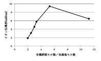
- FIG. 3 suggests that the maximum value of ionic conductivity is in the vicinity of a molar ratio of 6 in the electrolytic solution in which the metal salt is LiPF 6 and the organic solvent is DMC. Therefore, from the viewpoint of ionic conductivity, the electrolyte solution in which the metal salt is LiPF 6 and the organic solvent is DMC is preferably in the molar ratio range of 4 to 8, more preferably in the molar ratio range of 5 to 7. It can be said that the molar ratio in the range of 5 to 6 is more preferable.
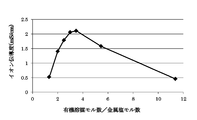
- FIG. 4 suggests that the maximum value of ionic conductivity is in the range of 3 to 4 in the electrolyte solution in which the metal salt is LiBF 4 and the organic solvent is DMC. Therefore, from the viewpoint of ionic conductivity, the electrolytic solution in which the metal salt is LiBF 4 and the organic solvent is DMC is preferably in the molar ratio range of 2 to 6, more preferably in the molar ratio range of 3 to 5. It can be said that the range of 4 is more preferable.
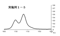
- FIGS. 5 and 6 show IR spectra in the range of 1600 to 1800 cm ⁇ 1 for the electrolytic solution of Example 1-5 and the electrolytic solution of Comparative Example 2-1, respectively.
- the horizontal axis represents the wave number (cm ⁇ 1 )
- the vertical axis represents the absorbance (reflection absorbance).
- IR measurement conditions Device FT-IR (Bruker Optics) Measurement conditions: ATR method (using diamond) Measurement atmosphere: Inert gas atmosphere
- Tables 4-1 and 4-2 show Io and Is observed in the IR spectrum of each electrolyte and their relationship.
- Example 1-1 The results of Example 1-1, Examples 1-3 to 1-5 and Comparative Example 2-1, and Examples 4-1, 4-2, 4-4 and 4- From the results of 5 and Comparative Example 3-1, it can be said that as the value of the number of moles of organic solvent / number of moles of metal salt increases, the value of Io tends to increase and the value of Is tends to decrease. This phenomenon means that as the value of the number of moles of organic solvent / number of moles of metal salt increases, the number of organic solvents not coordinated with the metal salt increases.
- Example 1-5 From the results of Examples 1-1 to 1-5, it can be seen that the larger the molar ratio between the organic solvent and the metal salt, that is, the closer to the conventional value, the easier the solidification at a low temperature. Further, from the results of Example 1-3 and Example 4-4, it can be said that the electrolyte solution having a metal salt of LiPF 6 is superior in low-temperature fluidity as compared with the electrolyte solution having a metal salt of LiBF 4. . Furthermore, when comparing the results of electrolyte solutions having similar molar ratios such as Examples 1-1 to 1-3, 2-1, and 3-1, the low-temperature fluidity of electrolyte solutions using DMC or EMC as a solvent is as follows. It can be said that it is superior to the electrolytic solution using DEC as a solvent.
- Example A-1-1 A half cell using the electrolyte solution of Example 1-1 was produced as follows.
- As the separator glass fiber filter paper (GE Healthcare Japan, Model No. 1825-055, Whatman glass fiber filter paper thickness 400 ⁇ m) was used.
- a working cell, a counter electrode, a separator, and the electrolyte solution of Example 1-1 were accommodated in a battery case (CR2032 type coin cell case manufactured by Hosen Co., Ltd.) to form a half cell. This was designated as the half cell of Example A-1-1.
- Example A-1-2 A half cell of Example A-1-2 was produced in the same manner as in Example A-1-1 except that the electrolyte solution of Example 1-2 was used.
- Example A-1-3 A half cell of Example A-1-3 was produced in the same manner as in Example A-1-1 except that the electrolyte solution of Example 1-3 was used.
- Example A-1-5 A half cell of Example A-1-5 was produced in the same manner as in Example A-1-1 except that the electrolyte solution of Example 1-5 was used.
- Example A-2-1 A half cell of Example A-2-1 was produced in the same manner as in Example A-1-1 except that the electrolyte solution of Example 2-1 was used.
- Example A-3-1 A half cell of Example A-3-1 was produced in the same manner as in Example A-1-1 except that the electrolyte solution of Example 3-1 was used.
- Example A-4-1 A half cell of Example A-4-1 was produced in the same manner as in Example A-1-1 except that the electrolyte solution of Example 4-1 was used.
- Example A-4-3 A half cell of Example A-4-3 was produced in the same manner as in Example A-1-1 except that the electrolyte solution of Example 4-3 was used.
- Example A-4-4-4 A half cell of Example A-4-4 was produced in the same manner as in Example A-1-1 except that the electrolyte solution of Example 4-4 was used.
- Example A-4-6 A half cell of Example A-4-6 was produced in the same manner as in Example A-1-1 except that the electrolyte solution of Example 4-6 was used.
- Example A-5-1 A half cell of Example A-5-1 was produced in the same manner as in Example A-1-1 except that the electrolyte solution of Example 5-1 was used.
- Example A-6-1 A half cell of Example A-6-1 was produced in the same manner as in Example A-1-1 except that the electrolyte solution of Example 6-1 was used.
- Comparative Example A-2-1 A half cell of Comparative Example A-2-1 was produced in the same manner as in Example A-1-1 except that the electrolytic solution of Comparative Example 2-1 was used.
- Comparative Example A-4-1 A half cell of Comparative Example A-4-1 was produced in the same manner as in Example A-1-1 except that the electrolytic solution of Comparative Example 4-1 was used.
- the half cell of Example A-6-1 exhibited a significantly lower current value than the half cell of the comparative example under any voltage. Further, it can be said that the half cell using the electrolytic solution of the present invention showed a small current value as compared with the half cell using the electrolytic solution of Comparative Example 2-1 having a large value of the number of moles of organic solvent / number of moles of metal salt. . It is suggested that the electrolytic solution of the present invention has no significant oxidative decomposition of the electrolytic solution even at a high potential of 4.6 V, and is low corrosive to aluminum, thereby suppressing the oxidation of aluminum. It is also suggested that a stable film is formed on the aluminum foil by the electrolytic solution of the present invention.
- the electrolytic solution of the present invention can be said to be a suitable electrolytic solution for a power storage device using aluminum as a current collector.
- Example B-1-1 A lithium ion secondary battery of Example B-1-1 using the electrolyte solution of Example 1-1 was produced as follows.
- the counter electrode was metal Li.
- glass fiber filter paper GE Healthcare Japan Co., Ltd., model number 1825-055, Whatman glass fiber filter paper thickness 400 ⁇ m was used.
- Example 1-1 The separator sandwiched between the working electrode, the counter electrode, and both electrodes and the electrolyte solution of Example 1-1 were accommodated in a battery case (CR2032 type coin cell case manufactured by Hosen Co., Ltd.) to form a half cell. This was designated as the lithium ion secondary battery of Example B-1-1.
- Example B-1-3 A lithium ion secondary battery of Example B-1-3 was produced in the same manner as in Example B-1-1 except that the electrolytic solution of Example 1-3 was used.
- Example B-1-5 A lithium ion secondary battery of Example B-1-5 was produced in the same manner as in Example B-1-1 except that the electrolyte solution of Example 1-5 was used.
- Example B-2-1 A lithium ion secondary battery of Example B-2-1 was produced in the same manner as in Example B-1-1 except that the electrolyte solution of Example 2-1 was used.
- Example B-3-1 A lithium ion secondary battery of Example B-3-1 was produced in the same manner as in Example B-1-1 except that the electrolyte solution of Example 3-1 was used.
- Example B-4-1 A lithium ion secondary battery of Example B-4-1 was produced in the same manner as in Example B-1-1 except that the electrolytic solution of Example 4-1 was used.
- Example B-4-2 A lithium ion secondary battery of Example B-4-2 was produced in the same manner as in Example B-1-1 except that the electrolyte solution of Example 4-2 was used.
- Example B-4-4-4 A lithium ion secondary battery of Example B-4-4 was produced in the same manner as in Example B-1-1 except that the electrolyte solution of Example 4-4 was used.
- Example B-4-6 A lithium ion secondary battery of Example B-4-6 was produced in the same manner as in Example B-1-1 except that the electrolyte solution of Example 4-6 was used.
- Comparative Example B-2-1 A lithium ion secondary battery of Comparative Example B-2-1 was produced in the same manner as in Example B-1-1 except that the electrolytic solution of Comparative Example 2-1 was used.
- Comparative Example B-3-1 A lithium ion secondary battery of Comparative Example B-3-1 was produced in the same manner as in Example B-1-1 except that the electrolytic solution of Comparative Example 3-1 was used.
- Comparative Example B-4-1 A lithium ion secondary battery of Comparative Example B-4-1 was produced in the same manner as in Example B-1-1 except that the electrolytic solution of Comparative Example 4-1 was used.
- the secondary battery comprising the electrolyte solution of the present invention and the positive electrode active material having a layered rock salt structure is reversibly charged and discharged.
- the secondary battery comprising the electrolytic solution of the present invention having DMC has all of the initial discharge capacity, the initial efficiency, and the capacity maintenance ratio equal to or greater than those of the secondary battery comprising the conventional electrolytic solution. Met.
- the electrolyte solution of the present invention is capable of inserting / extracting lithium to / from the lithium site. It can be said that a reversible reaction can be performed with respect to the positive electrode active material and the polarizable electrode material that act in the desorption reaction. It is estimated that most of the specific positive electrode active materials and polarizable materials described above correspond to such active materials.
- Example B-2 The lithium ion secondary batteries of Example B-1-5, Comparative Example B-2-1, and Comparative Example B-4-1 were charged from 3.1 V to 4.2 V and from 4.2 V at room temperature.
- a charge / discharge cycle test was performed in which discharge to 3.1 V was performed three times for each rate in the order of 0.1 C, 0.2 C, 0.5 C, 1 C, 2 C, 5 C, and 10 C rates.
- Table 8 shows the result of calculating the ratio of the discharge capacity at each rate to the discharge capacity at the 0.1 C rate.
- the counter electrode is regarded as a negative electrode and the working electrode is regarded as a positive electrode.
- 1C means a current value required to fully charge or discharge a battery in one hour at a constant current.
- the lithium ion secondary battery of Example B-1-5 is excellent in that the capacity decrease at each rate is suppressed as compared with the lithium ion secondary battery of each comparative example.
- the rate characteristics are shown. It was confirmed that the secondary battery comprising the electrolytic solution of the present invention and the positive electrode active material having a layered rock salt structure exhibits excellent rate characteristics.
- Example C-1-1 A lithium ion secondary battery of Example C-1-1 using the electrolyte solution of Example 1-1 was produced as follows.
- the counter electrode was metal Li.
- glass fiber filter paper GE Healthcare Japan Co., Ltd., model number 1825-055, Whatman glass fiber filter paper thickness 400 ⁇ m was used.
- Example C-1-1 The separator sandwiched between the working electrode, the counter electrode, and both electrodes and the electrolyte solution of Example 1-1 were accommodated in a battery case (CR2032 type coin cell case manufactured by Hosen Co., Ltd.) to form a half cell. This was designated as the lithium ion secondary battery of Example C-1-1.
- Example C-1-3 A lithium ion secondary battery of Example C-1-3 was produced in the same manner as in Example C-1-1 except that the electrolytic solution of Example 1-3 was used.
- Example C-1-5 A lithium ion secondary battery of Example C-1-5 was produced in the same manner as in Example C-1-1 except that the electrolyte solution of Example 1-5 was used.
- Example C-2-1 A lithium ion secondary battery of Example C-2-1 was produced in the same manner as in Example C-1-1 except that the electrolytic solution of Example 2-1 was used.
- Example C-3-1 A lithium ion secondary battery of Example C-3-1 was produced in the same manner as in Example C-1-1 except that the electrolyte solution of Example 3-1 was used.
- Example C-4-4-4 A lithium ion secondary battery of Example C-4-4 was produced in the same manner as in Example C-1-1 except that the electrolytic solution of Example 4-4 was used.
- Comparative Example C-2-1 A lithium ion secondary battery of Comparative Example C-2-1 was produced in the same manner as in Example C-1-1 except that the electrolytic solution of Comparative Example 2-1 was used.
- Comparative Example C-4-1 A lithium ion secondary battery of Comparative Example C-4-1 was produced in the same manner as in Example C-1-1 except that the electrolytic solution of Comparative Example 4-1 was used.
- the secondary battery comprising the electrolytic solution of the present invention and graphite is reversibly charged and discharged.
- the lithium ion secondary batteries of Example C-1-3 and Example C-1-5 were in good balance between initial discharge capacity, initial efficiency, and capacity retention rate.
- the metal salt is LiPF 6
- the organic solvent is DMC
- the organic solvent mole number / metal salt mole number is about 2.5 to 8, more preferably 4 to 8 It can be said that this electrolyte solution can react reversibly suitably with respect to the negative electrode which comprises graphite.
- an electrolytic solution having a cyclic carbonate such as EC was considered to be essential.
- the electrolytic solution of the present invention shows that reversible charging / discharging is possible with respect to the negative electrode including graphite, and among the electrolytic solution of the present invention, An electrolyte solution having a metal salt of LiPF 6 , an organic solvent of DMC, and an organic solvent mole number / metal salt mole number of about 2.5 to 8 should exhibit the same charge / discharge characteristics as a conventional EC-containing electrolyte solution. Has been demonstrated.
- the electrolytic solution of the present invention has a reversible lithium adsorption / desorption reaction with graphite, which is easy to reduce and decompose the electrolytic solution, because the ultimate potential when Li is occluded is as low as 0 V (vs Li / Li +). Met. Therefore, it can be said that the electrolytic solution of the present invention can react reversibly also with a negative electrode active material or activated carbon or other polarizable material, which has a higher lithium adsorption / desorption reaction potential than graphite and is less susceptible to reductive decomposition.
- FIG. 11 shows an overwriting with the enlarged charge / discharge curve of the battery.
- the lithium ion secondary battery of Example C-1-5 is superior in capacity reduction at each rate as compared with the lithium ion secondary battery of each comparative example.
- the rate characteristics are shown.
- the metal salt is LiPF 6
- the organic solvent is DMC
- Example D-1-5 A lithium ion secondary battery of Example D-1-5 using the electrolytic solution of Example 1-5 was produced as follows.
- This aluminum foil was pressed to obtain a bonded product.
- the obtained joined product was heat-dried at 120 ° C. for 6 hours with a vacuum dryer to obtain an aluminum foil on which a positive electrode active material layer was formed. This was used as a positive electrode.
- the positive electrode active material layer was formed on the positive electrode current collector at 6 mg / cm 2 per unit area of the coated surface, and the density of the positive electrode active material layer was 2.5 g / cm 3 .
- a negative electrode active material As a negative electrode active material, 98 parts by mass of spherical graphite, 1 part by mass of styrene butadiene rubber as a binder and 1 part by mass of carboxymethyl cellulose were mixed. This mixture was dispersed in an appropriate amount of ion-exchanged water to prepare a slurry. A copper foil having a thickness of 10 ⁇ m was prepared as a negative electrode current collector. The slurry was applied in a film form on the surface of the copper foil using a doctor blade. The copper foil coated with the slurry was dried to remove water, and then the copper foil was pressed to obtain a bonded product. The obtained joined product was dried by heating at 100 ° C.
- the negative electrode active material layer was formed on the negative electrode current collector at 4 mg / cm 2 per unit area of the coated surface, and the density of the negative electrode active material layer was 1.1 g / cm 3 .
- a separator As a separator, a polypropylene porous membrane having a thickness of 20 ⁇ m was prepared. A separator was sandwiched between the positive electrode and the negative electrode to form an electrode plate group. The electrode plate group was covered with a set of two laminated films, the three sides were sealed, and then the electrolyte solution of Example 1-5 was injected into the bag-like laminated film. Thereafter, the remaining one side was sealed to obtain a lithium ion secondary battery in which the four sides were hermetically sealed and the electrode plate group and the electrolyte were sealed. This was designated as the lithium ion secondary battery of Example D-1-5.
- Example D-1-6 A lithium ion secondary battery of Example D-1-6 was produced in the same manner as in Example D-1-5, except that the electrolyte solution of Example 1-6 was used.
- the lithium ion secondary battery of the present invention comprising a layered rock salt structure compound as the positive electrode active material and graphite as the negative electrode active material operates suitably. From the results of both lithium ion secondary batteries, it can be said that the addition of vinylene carbonate to the electrolytic solution of the present invention contributes to the reduction of DC resistance and the improvement of the capacity retention rate.
Landscapes
- Chemical & Material Sciences (AREA)
- Engineering & Computer Science (AREA)
- Chemical Kinetics & Catalysis (AREA)
- Electrochemistry (AREA)
- Power Engineering (AREA)
- General Chemical & Material Sciences (AREA)
- Microelectronics & Electronic Packaging (AREA)
- Inorganic Chemistry (AREA)
- Manufacturing & Machinery (AREA)
- Materials Engineering (AREA)
- Physics & Mathematics (AREA)
- General Physics & Mathematics (AREA)
- Condensed Matter Physics & Semiconductors (AREA)
- Organic Chemistry (AREA)
- Secondary Cells (AREA)
- Electric Double-Layer Capacitors Or The Like (AREA)
- Cell Electrode Carriers And Collectors (AREA)
- Battery Electrode And Active Subsutance (AREA)
- Primary Cells (AREA)
Abstract
Description
下記一般式(1-1)で表される鎖状カーボネート、下記一般式(1-2)で表されるエステル及び下記一般式(1-3)で表されるリン酸エステルから選択される特定有機溶媒が、
アルカリ金属、アルカリ土類金属又はアルミニウムをカチオンとし、ホウ素、炭素、酸素、ハロゲン、リン及びヒ素から選択される2又は3種類の元素で構成される化学構造をアニオンとする金属塩に対し、
モル比1~8で含まれること特徴とする。
R12COOR13 一般式(1-2)
OP(OR14)(OR15)(OR16) 一般式(1-3)
(R10、R11、R12、R13、R14、R15、R16は、それぞれ独立に、鎖状アルキルであるCnHaFbClcBrdIe、又は、環状アルキルを化学構造に含むCmHfFgClhBriIjのいずれかから選択される。nは1以上の整数、mは3以上の整数、a、b、c、d、e、f、g、h、i、jはそれぞれ独立に0以上の整数であり、2n+1=a+b+c+d+e、2m=f+g+h+i+jを満たす。)
下記一般式(1-1)で表される鎖状カーボネート、下記一般式(1-2)で表されるエステル及び下記一般式(1-3)で表されるリン酸エステルから選択される特定有機溶媒が、
アルカリ金属、アルカリ土類金属又はアルミニウムをカチオンとし、ホウ素、炭素、酸素、ハロゲン、リン及びヒ素から選択される2又は3種類の元素で構成される化学構造をアニオンとする金属塩に対し、
モル比1~8で含まれること特徴とする。
R12COOR13 一般式(1-2)
OP(OR14)(OR15)(OR16) 一般式(1-3)
(R10、R11、R12、R13、R14、R15、R16は、それぞれ独立に、鎖状アルキルであるCnHaFbClcBrdIe、又は、環状アルキルを化学構造に含むCmHfFgClhBriIjのいずれかから選択される。nは1以上の整数、mは3以上の整数、a、b、c、d、e、f、g、h、i、jはそれぞれ独立に0以上の整数であり、2n+1=a+b+c+d+e、2m=f+g+h+i+jを満たす。)
ここで、
L:結晶子の大きさ
λ:入射X線波長(1.54Å)
β:ピークの半値幅(ラジアン)
θ:回折角
なお、上記したSiOxにおいては、リチウムイオン二次電池の充放電時にリチウムとSi相のケイ素とによる合金化反応が生じると考えられている。そして、この合金化反応がリチウムイオン二次電池の充放電に寄与すると考えられている。後述するスズを含む負極活物質についても、同様に、スズとリチウムとの合金化反応によって充放電できると考えられている。
より具体的な層状岩塩構造の化合物として、LiNi0.5Co0.3Mn0.2O2、LiNi0.5Co0.2Mn0.3O2、LiNi1/3Co1/3Mn1/3O2、LiNi0.5Mn0.5O2、LiNi0.75Co0.1Mn0.15O2、LiMnO2、LiNiO2、及びLiCoO2を例示できる。他の具体的な正極活物質として、Li2MnO3-LiCoO2を例示できる。
正極及び負極に必要に応じてセパレータを挟装させ電極体とする。電極体は、正極、セパレータ及び負極を重ねた積層型、又は、正極、セパレータ及び負極を捲いた捲回型のいずれの型にしても良い。正極の集電体及び負極の集電体から外部に通ずる正極端子及び負極端子までの間を、集電用リード等を用いて接続した後に、電極体に本発明の電解液を加えてリチウムイオン二次電池とするとよい。また、本発明のリチウムイオン二次電池は、電極に含まれる活物質の種類に適した電圧範囲で充放電を実行されればよい。
一般式(1-1)で表される鎖状カーボネートであるDMC約5mLを、撹拌子を備えたフラスコに入れた。撹拌条件下にて、上記フラスコ中のDMCに対し、金属塩であるLiPF6を徐々に加え、溶解させた。LiPF6を全量で10.01g加え、さらにDMCの全量が11.50gとなるようにDMCを追加して、撹拌した。若干のLiPF6の溶け残りを視認したため、DMCの全量が11.87gとなるようにDMCを追加してLiPF6を溶解した。この溶液を実施例1-1の電解液とした。なお、上記製造は不活性ガス雰囲気下のグローブボックス内で行った。
実施例1-1の電解液におけるLiPF6の濃度は4.4mol/Lであった。実施例1-1の電解液においては、LiPF61モルに対しDMC2モルが含まれている。
一般式(1-1)で表される鎖状カーボネートであるDMC約5mLを、撹拌子を備えたフラスコに入れた。撹拌条件下にて、上記フラスコ中のDMCに対し、金属塩であるLiPF6を徐々に加え、溶解させた。LiPF6を全量で8.02g加え、さらにDMCの全量が11.89gとなるようにDMCを追加してLiPF6を溶解させた。この溶液を実施例1-2の電解液とした。なお、上記製造は不活性ガス雰囲気下のグローブボックス内で行った。
実施例1-2の電解液におけるLiPF6の濃度は3.75mol/Lであった。実施例1-2の電解液においては、LiPF61モルに対しDMC2.5モルが含まれている。
LiPF6を全量で6.99g、DMCを全量で12.43g用いた以外は、実施例1-2と同様の方法で、実施例1-3の電解液を製造した。実施例1-3の電解液におけるLiPF6の濃度は3.19mol/Lであった。実施例1-3の電解液においては、LiPF61モルに対しDMC3モルが含まれている。
実施例1-2の電解液8.02mLを10mLのメスフラスコに移し、DMCを加えて溶液の容積を10mLとした。これを実施例1-4の電解液とした。なお、上記製造は不活性ガス雰囲気下のグローブボックス内で行った。実施例1-4の電解液におけるLiPF6の濃度は3mol/Lであった。実施例1-4の電解液においては、LiPF61モルに対しDMC3.31モルが含まれている。
実施例1-4の電解液6.67mLを用いた以外は、実施例1-4と同様の方法で、実施例1-5の電解液を製造した。実施例1-5の電解液におけるLiPF6の濃度は2mol/Lであった。実施例1-5の電解液においては、LiPF61モルに対しDMC5.31モルが含まれている。
ビニレンカーボネートを電解液全体に対して0.2質量%となるように添加した以外は、実施例1-5と同様の方法で、実施例1-6の電解液を製造した。実施例1-6の電解液におけるLiPF6の濃度は2mol/Lであった。実施例1-6の電解液においては、LiPF61モルに対しDMC5.31モルが含まれている。
一般式(1-1)で表される鎖状カーボネートであるEMC約5mLを、撹拌子を備えたフラスコに入れた。撹拌条件下にて、上記フラスコ中のEMCに対し、金属塩であるLiPF6を徐々に加え、溶解させた。LiPF6を全量で8.01g加え、さらにEMCの全量が10.98gとなるようにEMCを追加して、撹拌した。若干のLiPF6の溶け残りを視認したため、EMCの全量が11.78gとなるようにEMCを追加してLiPF6を溶解した。この溶液を実施例2-1の電解液とした。なお、上記製造は不活性ガス雰囲気下のグローブボックス内で行った。
実施例2-1の電解液におけるLiPF6の濃度は3.58mol/Lであった。実施例2-1の電解液においては、LiPF61モルに対しEMC2.15モルが含まれている。
一般式(1-1)で表される鎖状カーボネートであるDEC約5mLを、撹拌子を備えたフラスコに入れた。撹拌条件下にて、上記フラスコ中のDECに対し、金属塩であるLiPF6を徐々に加え、溶解させた。LiPF6を全量で8.01g加え、さらにEMCの全量が12.46gとなるようにDECを追加して、撹拌した。若干のLiPF6の溶け残りを視認したため、DECの全量が16.72gとなるようにDECを追加してLiPF6を溶解した。この溶液を実施例3-1の電解液とした。なお、上記製造は不活性ガス雰囲気下のグローブボックス内で行った。
実施例3-1の電解液におけるLiPF6の濃度は2.62mol/Lであった。実施例3-1の電解液においては、LiPF61モルに対しDEC2.69モルが含まれている。
一般式(1-1)で表される鎖状カーボネートであるDMC約5mLを、撹拌子を備えたフラスコに入れた。撹拌条件下にて、上記フラスコ中のDMCに対し、金属塩であるLiBF4を徐々に加え、溶解させた。LiBF4を全量で10g加え、さらにDMCの全量が9.61gとなるようにDMCを追加して、撹拌した。若干のLiBF4の溶け残りを視認したため、DMCの全量が12.74gとなるようにDMCを追加してLiBF4を溶解した。この溶液を実施例4-1の電解液とした。なお、上記製造は不活性ガス雰囲気下のグローブボックス内で行った。
実施例4-1の電解液におけるLiBF4の濃度は6.46mol/Lであった。実施例4-1の電解液においては、LiBF41モルに対しDMC1.33モルが含まれている。
一般式(1-1)で表される鎖状カーボネートであるDMC約5mLを、撹拌子を備えたフラスコに入れた。撹拌条件下にて、上記フラスコ中のDMCに対し、金属塩であるLiBF4を徐々に加え、溶解させた。LiBF4を全量で10g加え、さらにDMCの全量が19.22gとなるようにDMCを追加してLiBF4を溶解させた。この溶液を実施例4-2の電解液とした。なお、上記製造は不活性ガス雰囲気下のグローブボックス内で行った。
実施例4-2の電解液におけるLiBF4の濃度は4.92mol/Lであった。実施例4-2の電解液においては、LiBF41モルに対しDMC2モルが含まれている。
LiBF4を全量で5.01g、DMCを全量で12.03g用いた以外は、実施例4-2と同様の方法で、実施例4-3の電解液を製造した。実施例4-3の電解液におけるLiBF4の濃度は3.99mol/Lであった。実施例4-3の電解液においては、LiBF41モルに対しDMC2.5モルが含まれている。
LiBF4を全量で5g、DMCを全量で14.41g用いた以外は、実施例4-2と同様の方法で、実施例4-4の電解液を製造した。実施例4-4の電解液におけるLiBF4の濃度は3.42mol/Lであった。実施例4-4の電解液においては、LiBF41モルに対しDMC3モルが含まれている。
実施例4-2の電解液6.10mLを10mLのメスフラスコに移し、DMCを加えて溶液の容積を10mLとした。これを実施例4-5の電解液とした。なお、上記製造は不活性ガス雰囲気下のグローブボックス内で行った。実施例4-5の電解液におけるLiBF4の濃度は3mol/Lであった。実施例4-5の電解液においては、LiBF41モルに対しDMC3.48モルが含まれている。
実施例4-2の電解液4.07mLを用いた以外は、実施例4-5と同様の方法で、実施例4-6の電解液を製造した。実施例4-6の電解液におけるLiBF4の濃度は2mol/Lであった。実施例4-6の電解液においては、LiBF41モルに対しDMC5.46モルが含まれている。
一般式(1-1)で表される鎖状カーボネートであるEMC約5mLを、撹拌子を備えたフラスコに入れた。撹拌条件下にて、上記フラスコ中のEMCに対し、金属塩であるLiBF4を徐々に加え、溶解させた。LiBF4を全量で6.01g加え、さらにEMCの全量が13.35gとなるようにEMCを追加してLiBF4を溶解させた。この溶液を実施例5-1の電解液とした。なお、上記製造は不活性ガス雰囲気下のグローブボックス内で行った。
実施例5-1の電解液におけるLiBF4の濃度は4.04mol/Lであった。実施例5-1の電解液においては、LiBF41モルに対しEMC2モルが含まれている。
一般式(1-1)で表される鎖状カーボネートであるDEC約5mLを、撹拌子を備えたフラスコに入れた。撹拌条件下にて、上記フラスコ中のDECに対し、金属塩であるLiBF4を徐々に加え、溶解させた。LiBF4を全量で6g加え、さらにDECの全量が15.12gとなるようにDECを追加して、撹拌した。若干のLiBF4の溶け残りを視認したため、DECの全量が16.84gとなるようにDECを追加してLiBF4を溶解した。この溶液を実施例6-1の電解液とした。なお、上記製造は不活性ガス雰囲気下のグローブボックス内で行った。
実施例6-1の電解液におけるLiBF4の濃度は3.19mol/Lであった。実施例6-1の電解液においては、LiBF41モルに対しDEC2.23モルが含まれている。
アセトニトリル約5mLを、撹拌子を備えたフラスコに入れた。撹拌条件下にて、上記フラスコ中のアセトニトリルに対し、金属塩であるLiPF6を徐々に加えた。LiPF6を全量で10.01g加え、さらにアセトニトリルの全量が5.41gとなるようにアセトニトリルを追加して、撹拌した。LiPF6の溶け残りを視認したため、溶液を80℃まで加熱し、撹拌したものの、依然としてLiPF6の溶け残りを視認した。アセトニトリル5.41gにLiPF610.01gを溶解させることはできなかった。なお、アセトニトリル5.41gにLiPF610.01gが溶解した場合の溶液には、LiPF61モルに対しアセトニトリル2モルが含まれる予定であった。
1,2-ジメトキシエタン約5mLを、撹拌子を備えたフラスコに入れた。撹拌条件下にて、上記フラスコ中の1,2-ジメトキシエタンに対し、金属塩であるLiPF6を徐々に加えた。LiPF6を全量で5g加え、さらに1,2-ジメトキシエタンの全量が5.93gとなるように1,2-ジメトキシエタンを追加して、撹拌した。LiPF6の溶け残りを視認したため、溶液を80℃まで加熱し、撹拌したものの、依然としてLiPF6の溶け残りを視認した。1,2-ジメトキシエタン5.93gにLiPF65gを溶解させることはできなかった。なお、1,2-ジメトキシエタン5.93gにLiPF65gが溶解した場合の溶液には、LiPF61モルに対し1,2-ジメトキシエタン2モルが含まれる予定であった。
N,N-ジメチルホルムアミド約5mLを、撹拌子を備えたフラスコに入れた。撹拌条件下にて、上記フラスコ中のN,N-ジメチルホルムアミドに対し、金属塩であるLiPF6を徐々に加えた。LiPF6を全量で7g加え、さらにN,N-ジメチルホルムアミドの全量が6.74gとなるようにN,N-ジメチルホルムアミドを追加して、撹拌した。LiPF6の溶け残りを視認したため、溶液を80℃まで加熱し、撹拌したものの、依然としてLiPF6の溶け残りを視認した。N,N-ジメチルホルムアミド6.74gにLiPF67gを溶解させることはできなかった。なお、N,N-ジメチルホルムアミド6.74gにLiPF67gが溶解した場合の溶液には、LiPF61モルに対しN,N-ジメチルホルムアミド2モルが含まれる予定であった。
実施例1-3の電解液3.13mLを用いた以外は、実施例1-4と同様の方法で、比較例2-1の電解液を製造した。比較例2-1の電解液におけるLiPF6の濃度は1mol/Lであった。比較例2-1の電解液においては、LiPF61モルに対しDMC11.24モルが含まれている。
実施例4-4の電解液2.92mLを用いた以外は、実施例4-5と同様の方法で、比較例3-1の電解液を製造した。比較例3-1の電解液におけるLiBF4の濃度は1mol/Lであった。比較例3-1の電解液においては、LiBF41モルに対しDMC11.37モルが含まれている。
エチレンカーボネート(以下、ECと略す場合がある。)、エチルメチルカーボネート及びジメチルカーボネートの混合溶媒(体積比3:3:4、以下、「EC/EMC/DMC」ということがある。)に、LiPF6を溶解させ、LiPF6の濃度が1.0mol/Lである比較例4-1の電解液を製造した。なお、上記製造は不活性ガス雰囲気下のグローブボックス内で行った。比較例4-1の電解液においては、LiPF61モルに対し概ねEC/EMC/DMC10モルが含まれている。

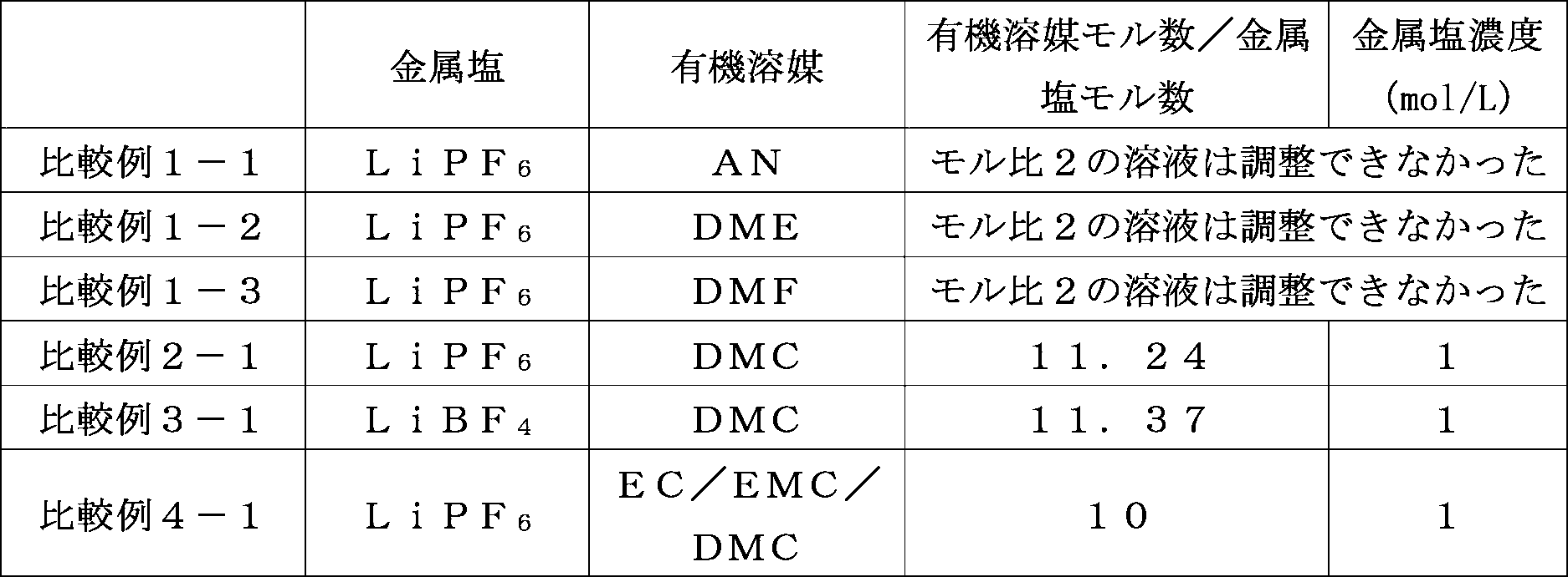
実施例及び比較例の電解液のイオン伝導度を以下の条件で測定した。結果を表2-1及び表2-2に示す。
Ar雰囲気下、白金極を備えたセル定数既知のガラス製セルに、電解液を封入し、25℃、10kHzでのインピーダンスを測定した。インピーダンスの測定結果から、イオン伝導度を算出した。測定機器はSolartron 147055BEC(ソーラトロン社)を使用した。
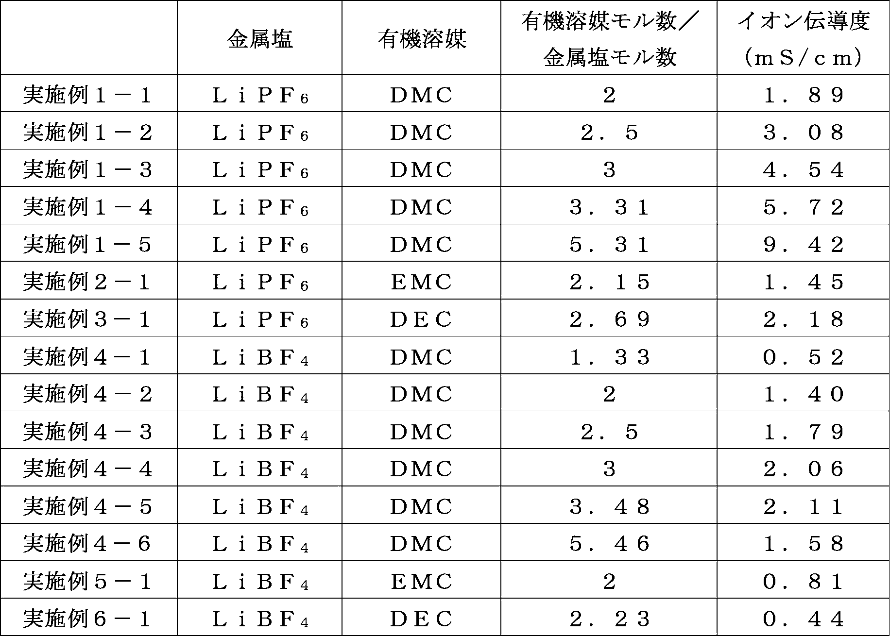

また、金属塩がLiBF4であり、有機溶媒がDMCである、実施例4-1~4-6、比較例3-1の電解液につき、金属塩に対する有機溶媒のモル比とイオン伝導度との関係をグラフにした。当該グラフを図4に示す。
実施例及び比較例の電解液の20℃における密度を測定した。結果を表3-1及び表3-2に示す。
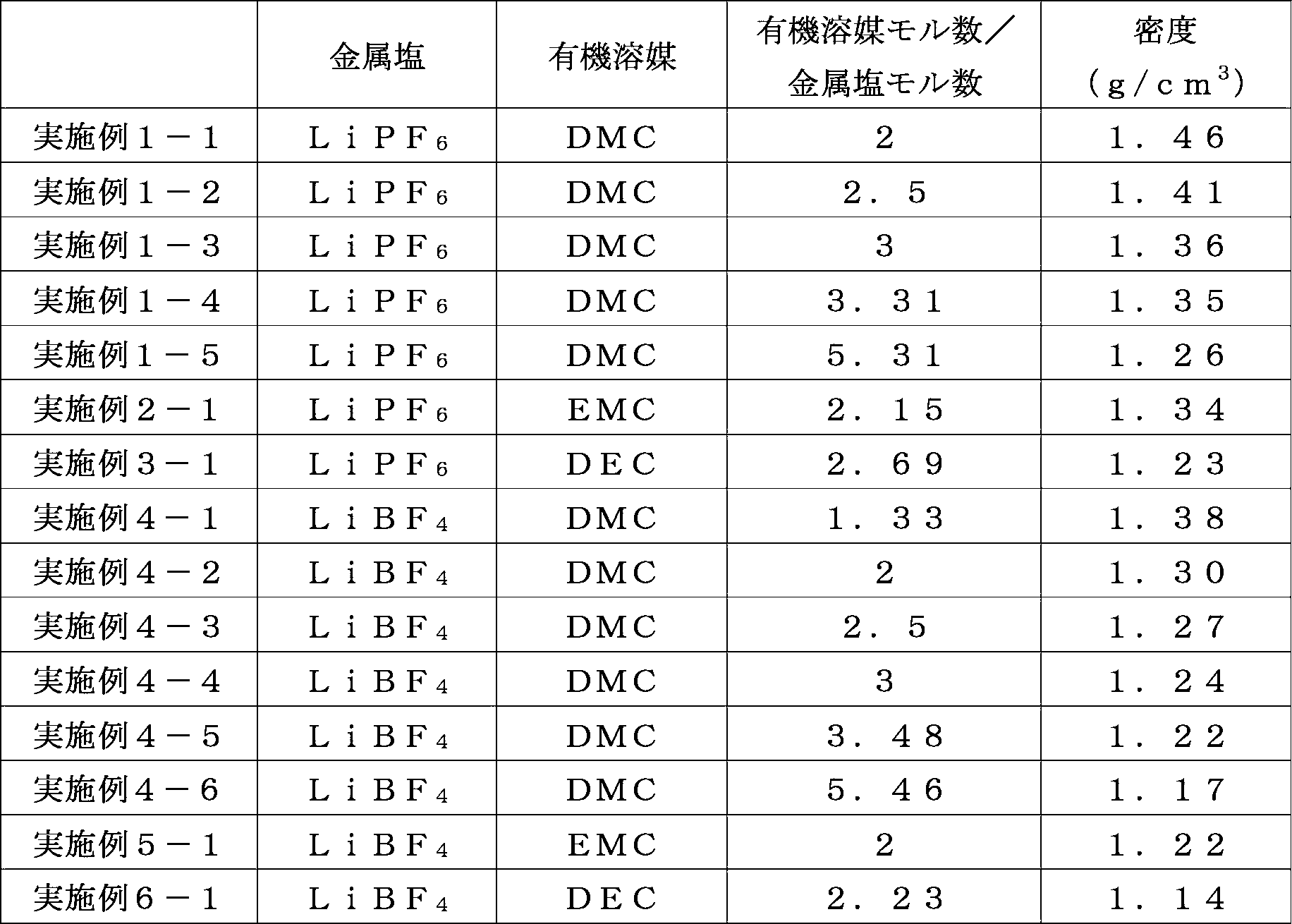
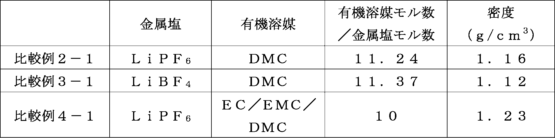
代表的な実施例及び比較例の電解液につき、以下の条件でIR測定を行った。実施例1-5の電解液及び比較例2-1の電解液について、1600~1800cm-1の範囲のIRスペクトルをそれぞれ図5、図6に示す。各図の横軸は波数(cm-1)であり、縦軸は吸光度(反射吸光度)である。
装置:FT-IR(ブルカーオプティクス社製)
測定条件:ATR法(ダイヤモンド使用)
測定雰囲気:不活性ガス雰囲気下
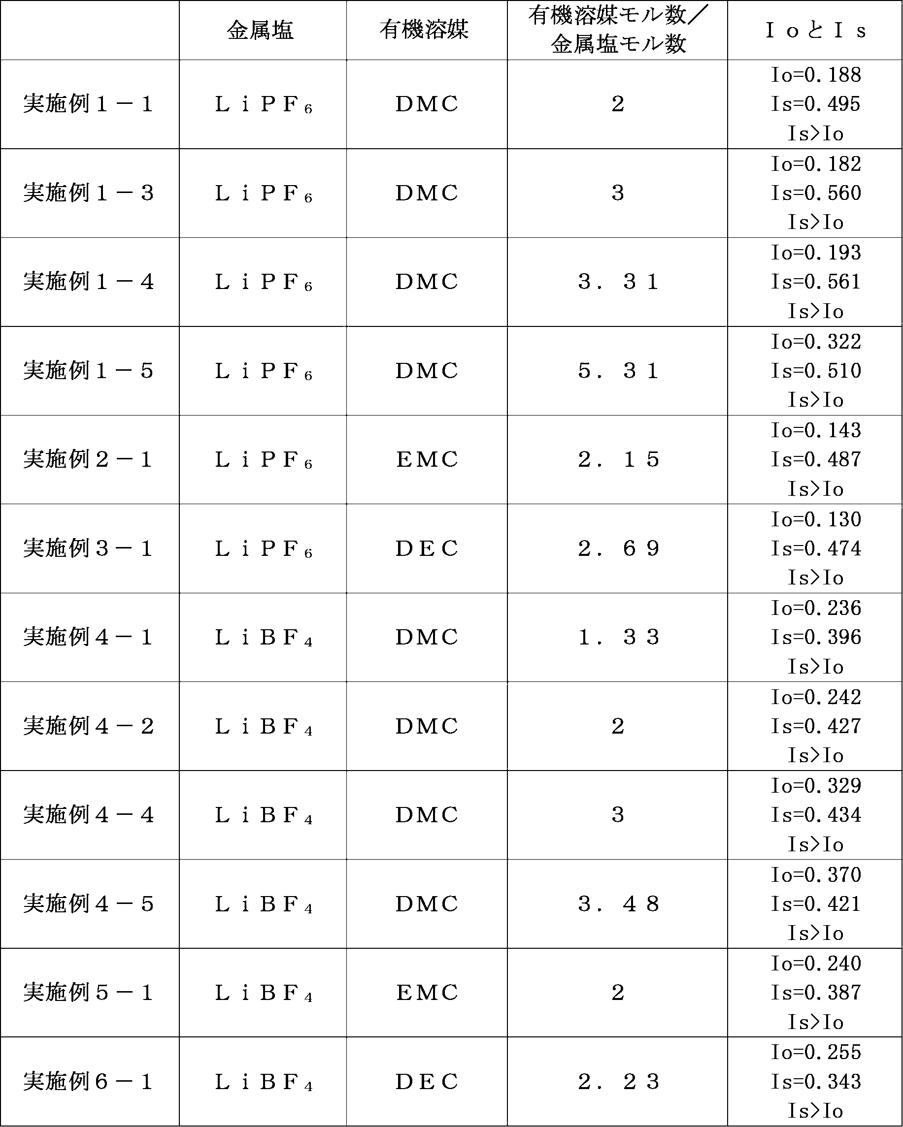
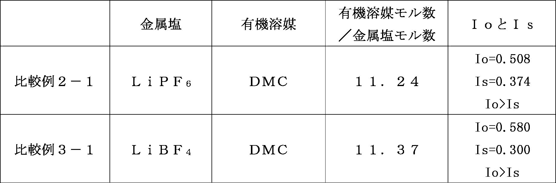
実施例の電解液をそれぞれ容器に入れ、不活性ガスを充填して密閉した。これらを-20℃の冷凍庫に2日間保管した。保管後に各容器を傾けて、電解液の流動性を観察した。結果を表5-1に示す。なお、表中の空欄は未測定を意味する。
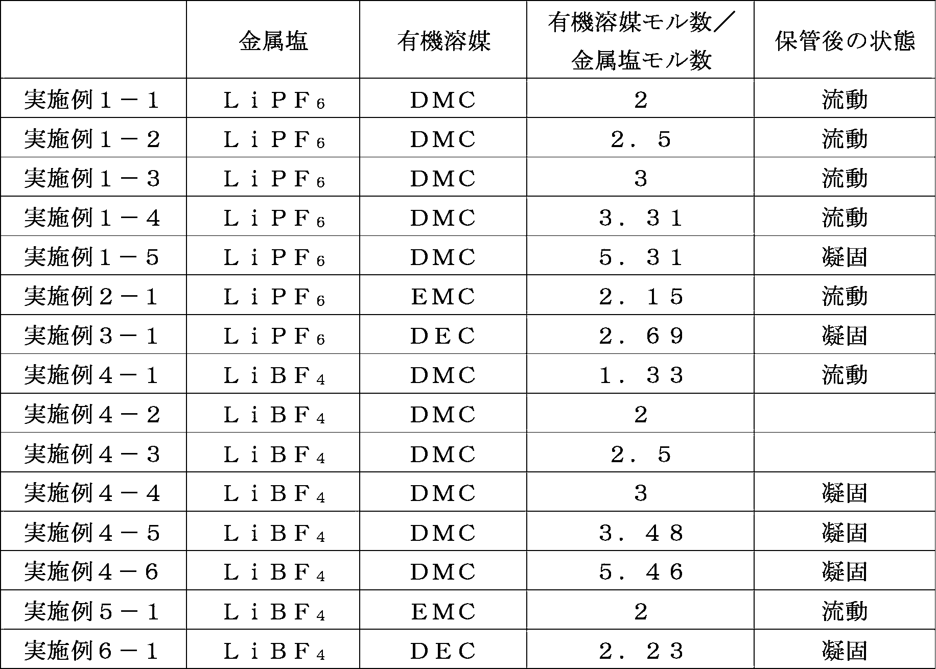
実施例1-1の電解液を用いたハーフセルを以下のとおり製造した。
径13.82mm、面積1.5cm2、厚み15μmのアルミニウム箔(JIS A1000番系)を作用極とし、対極は金属Liとした。セパレータは、ガラス繊維ろ紙(GEヘルスケア・ジャパン株式会社、型番1825-055、 Whatmanガラス繊維ろ紙 厚み400μm)を用いた。
作用極、対極、セパレータ及び実施例1-1の電解液を電池ケース(宝泉株式会社製 CR2032型コインセルケース)に収容しハーフセルを構成した。これを実施例A-1-1のハーフセルとした。
実施例1-2の電解液を用いた以外は、実施例A-1-1と同様の方法で、実施例A-1-2のハーフセルを作製した。
実施例1-3の電解液を用いた以外は、実施例A-1-1と同様の方法で、実施例A-1-3のハーフセルを作製した。
実施例1-5の電解液を用いた以外は、実施例A-1-1と同様の方法で、実施例A-1-5のハーフセルを作製した。
実施例2-1の電解液を用いた以外は、実施例A-1-1と同様の方法で、実施例A-2-1のハーフセルを作製した。
実施例3-1の電解液を用いた以外は、実施例A-1-1と同様の方法で、実施例A-3-1のハーフセルを作製した。
実施例4-1の電解液を用いた以外は、実施例A-1-1と同様の方法で、実施例A-4-1のハーフセルを作製した。
実施例4-3の電解液を用いた以外は、実施例A-1-1と同様の方法で、実施例A-4-3のハーフセルを作製した。
実施例4-4の電解液を用いた以外は、実施例A-1-1と同様の方法で、実施例A-4-4のハーフセルを作製した。
実施例4-6の電解液を用いた以外は、実施例A-1-1と同様の方法で、実施例A-4-6のハーフセルを作製した。
実施例5-1の電解液を用いた以外は、実施例A-1-1と同様の方法で、実施例A-5-1のハーフセルを作製した。
実施例6-1の電解液を用いた以外は、実施例A-1-1と同様の方法で、実施例A-6-1のハーフセルを作製した。
比較例2-1の電解液を用いた以外は、実施例A-1-1と同様の方法で、比較例A-2-1のハーフセルを作製した。
比較例4-1の電解液を用いた以外は、実施例A-1-1と同様の方法で、比較例A-4-1のハーフセルを作製した。
上記実施例及び比較例のハーフセルに対して、3.1V~4.6V、1mV/sの条件で6サイクルのサイクリックボルタンメトリー評価を行い、その後、連続して3.1V~5.1V、1mV/sの条件で6サイクルのサイクリックボルタンメトリー評価を行った。実施例A-1-5及び比較例A-4-1のハーフセルに対する電位と応答電流との関係を示すグラフを図7~図10に示す。各図の横軸は電位(V)であり、縦軸は応答電流(mA)である。また、それぞれの条件での6サイクル目における電圧増加時に観測された最大電流値を表6に示す。

実施例1-1の電解液を用いた実施例B-1-1のリチウムイオン二次電池を以下のとおり製造した。
実施例1-3の電解液を用いた以外は、実施例B-1-1と同様の方法で、実施例B-1-3のリチウムイオン二次電池を作製した。
実施例1-5の電解液を用いた以外は、実施例B-1-1と同様の方法で、実施例B-1-5のリチウムイオン二次電池を作製した。
実施例2-1の電解液を用いた以外は、実施例B-1-1と同様の方法で、実施例B-2-1のリチウムイオン二次電池を作製した。
実施例3-1の電解液を用いた以外は、実施例B-1-1と同様の方法で、実施例B-3-1のリチウムイオン二次電池を作製した。
実施例4-1の電解液を用いた以外は、実施例B-1-1と同様の方法で、実施例B-4-1のリチウムイオン二次電池を作製した。
実施例4-2の電解液を用いた以外は、実施例B-1-1と同様の方法で、実施例B-4-2のリチウムイオン二次電池を作製した。
実施例4-4の電解液を用いた以外は、実施例B-1-1と同様の方法で、実施例B-4-4のリチウムイオン二次電池を作製した。
実施例4-6の電解液を用いた以外は、実施例B-1-1と同様の方法で、実施例B-4-6のリチウムイオン二次電池を作製した。
比較例2-1の電解液を用いた以外は、実施例B-1-1と同様の方法で、比較例B-2-1のリチウムイオン二次電池を作製した。
比較例3-1の電解液を用いた以外は、実施例B-1-1と同様の方法で、比較例B-3-1のリチウムイオン二次電池を作製した。
比較例4-1の電解液を用いた以外は、実施例B-1-1と同様の方法で、比較例B-4-1のリチウムイオン二次電池を作製した。
各リチウムイオン二次電池に対し、電圧4.2Vまで定電流充電し、電圧3.1Vまで定電流放電を行うとの3.1V-4.2Vの充放電サイクルを、25℃、0.5Cレートの条件で、10サイクル行った。初期放電容量、(初期放電容量)/(初期充電容量)で算出される初期効率、及び、(10サイクル後の放電容量)/(初期放電容量)で算出される容量維持率の結果を表7に示す。なお、ここでの記述は、対極を負極、作用極を正極とみなしている。

実施例B-1-5、比較例B-2-1、比較例B-4-1のリチウムイオン二次電池に対し、室温で、3.1Vから4.2Vまでの充電及び4.2Vから3.1Vまでの放電を、0.1C、0.2C、0.5C、1C、2C、5C、10Cレートの順序で、各レートにつき3回ずつ行う充放電サイクル試験を行った。0.1Cレートでの放電容量に対する、各レートでの放電容量の比率を算出した結果を表8に示す。なお、ここでの記述は、対極を負極、作用極を正極とみなしている。1Cとは一定電流において1時間で電池を完全充電又は放電させるために要する電流値を意味する。

実施例1-1の電解液を用いた実施例C-1-1のリチウムイオン二次電池を以下のとおり製造した。
実施例1-3の電解液を用いた以外は、実施例C-1-1と同様の方法で、実施例C-1-3のリチウムイオン二次電池を作製した。
実施例1-5の電解液を用いた以外は、実施例C-1-1と同様の方法で、実施例C-1-5のリチウムイオン二次電池を作製した。
実施例2-1の電解液を用いた以外は、実施例C-1-1と同様の方法で、実施例C-2-1のリチウムイオン二次電池を作製した。
実施例3-1の電解液を用いた以外は、実施例C-1-1と同様の方法で、実施例C-3-1のリチウムイオン二次電池を作製した。
実施例4-4の電解液を用いた以外は、実施例C-1-1と同様の方法で、実施例C-4-4のリチウムイオン二次電池を作製した。
比較例2-1の電解液を用いた以外は、実施例C-1-1と同様の方法で、比較例C-2-1のリチウムイオン二次電池を作製した。
比較例4-1の電解液を用いた以外は、実施例C-1-1と同様の方法で、比較例C-4-1のリチウムイオン二次電池を作製した。
各リチウムイオン二次電池に対し、電圧2.0Vまで定電流放電し、電圧0.01Vまで定電流充電を行うとの2.0V-0.01Vの充放電サイクルを、25℃、0.5Cレートの条件で、10サイクル行った。初期放電容量、(初期充電容量)/(初期放電容量)で算出される初期効率、及び、(10サイクル後の放電容量)/(初期放電容量)で算出される容量維持率の結果を表9に示す。なお、ここでの記述は、対極を正極、作用極を負極とみなしている。
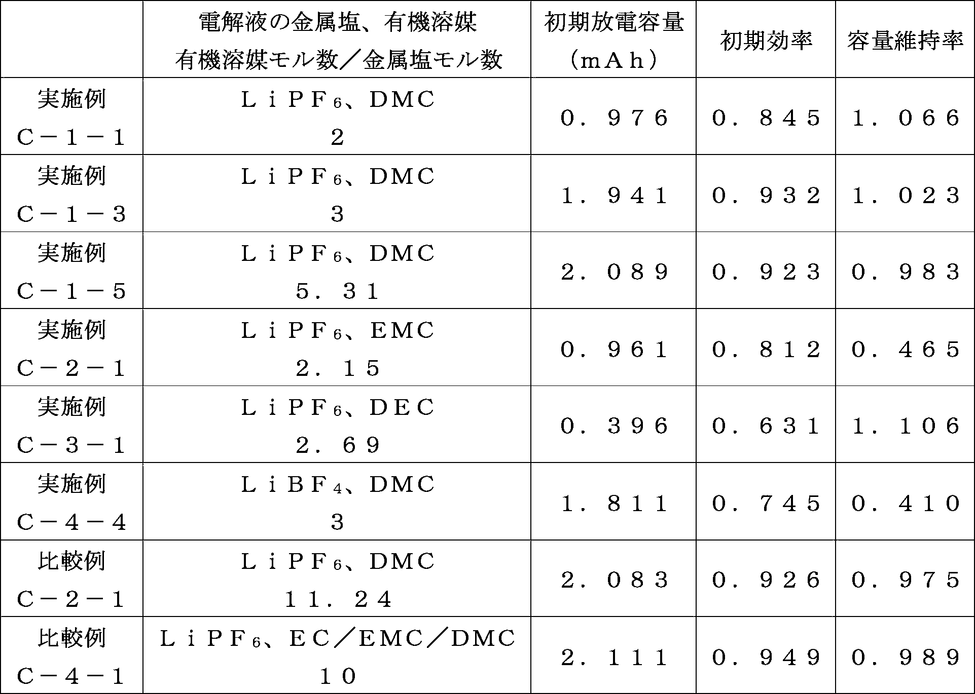
実施例C-1-5、比較例C-2-1、比較例C-4-1のリチウムイオン二次電池に対し、室温で、0.01Vから2Vまでの放電及び2Vから0.01Vまでの充電を、0.1C、0.2C、0.5C、1C、2C、5C、10Cレートの順序で、各レートにつき3回ずつ行う充放電サイクル試験を行った。0.1Cレートでの放電容量に対する、各レートでの放電容量の比率を算出した結果を表10に示す。なお、ここでの記述は、対極を正極、作用極を負極とみなしている。

実施例1-5の電解液を用いた実施例D-1-5のリチウムイオン二次電池を以下のとおり製造した。
実施例1-6の電解液を用いた以外は、実施例D-1-5と同様の方法で、実施例D-1-6のリチウムイオン二次電池を作製した。
実施例D-1-5及びD-1-6のリチウムイオン二次電池につき、温度-10℃、0.5Cレートの定電流にて3.65Vに調整した後、3Cレートで10秒の定電流充電をした。充電前後の電圧変化量及び電流値から、オームの法則により、充電時の直流抵抗を算出した。同様に、各リチウムイオン二次電池につき、温度-10℃、0.5Cレートの定電流にて3.65Vに調整した後、3Cレートで2秒の定電流放電をした。放電前後の電圧変化量及び電流値から、オームの法則により、放電時の直流抵抗を算出した。
実施例D-1-5及びD-1-6のリチウムイオン二次電池につき、温度25℃、1Cレートでの定電流で4.1Vまで充電し、1分間休止した後、1Cレートでの定電流で3.0Vまで放電し、1分間休止するとの充放電サイクルを100サイクル繰り返した。容量維持率を以下の式で算出した。
容量維持率(%)=100×(100サイクルでの放電容量)/(初回の放電容量)
評価例D-1及び評価例D-2の結果を表11に示す。

Claims (13)
- 下記一般式(1-1)で表される鎖状カーボネート、下記一般式(1-2)で表されるエステル及び下記一般式(1-3)で表されるリン酸エステルから選択される特定有機溶媒が、
アルカリ金属、アルカリ土類金属又はアルミニウムをカチオンとし、ホウ素、炭素、酸素、ハロゲン、リン及びヒ素から選択される2又は3種類の元素で構成される化学構造をアニオンとする金属塩に対し、
モル比1~8で含まれること特徴とする電解液。
R10OCOOR11 一般式(1-1)
R12COOR13 一般式(1-2)
OP(OR14)(OR15)(OR16) 一般式(1-3)
(R10、R11、R12、R13、R14、R15、R16は、それぞれ独立に、鎖状アルキルであるCnHaFbClcBrdIe、又は、環状アルキルを化学構造に含むCmHfFgClhBriIjのいずれかから選択される。nは1以上の整数、mは3以上の整数、a、b、c、d、e、f、g、h、i、jはそれぞれ独立に0以上の整数であり、2n+1=a+b+c+d+e、2m=f+g+h+i+jを満たす。) - 前記特定有機溶媒が、電解液に含まれる全溶媒に対して、70体積%以上で含まれる請求項1に記載の電解液。
- 前記特定有機溶媒が、電解液に含まれる全溶媒に対して、90体積%以上で含まれる請求項1又は2に記載の電解液。
- 前記R10、R11、R12、R13、R14、R15、R16が以下のとおりである請求項1~3のいずれかに記載の電解液。
(R10、R11、R12、R13、R14、R15、R16は、それぞれ独立に、鎖状アルキルであるCnHaFb、又は、環状アルキルを化学構造に含むCmHfFgのいずれかから選択される。nは1以上の整数、mは3以上の整数、a、b、f、gはそれぞれ独立に0以上の整数であり、2n+1=a+b、2m=f+gを満たす。) - 前記特定有機溶媒に関するnが1以上6以下の整数であり、mが3以上8以下の整数である請求項1~4のいずれかに記載の電解液。
- 前記特定有機溶媒が前記一般式(1-1)で表される鎖状カーボネートである請求項1~5のいずれかに記載の電解液。
- 前記金属塩のアニオンの化学構造がXO4、AsX6、PX6、BX4、B(C2O4)2のいずれか(Xはハロゲンを意味する。)である請求項1~6のいずれかに記載の電解液。
- 前記金属塩のアニオンの化学構造がPF6又はBF4である請求項1~7のいずれかに記載の電解液。
- 前記金属塩のアニオンの化学構造がPF6であり、前記モル比が4~8である請求項1~8のいずれかに記載の電解液。
- 前記金属塩のアニオンの化学構造がBF4であり、前記モル比が2~6である請求項1~8のいずれかに記載の電解液。
- 請求項1~10のいずれかに記載の電解液を具備する蓄電装置。
- 前記蓄電装置が二次電池又はキャパシタである請求項11に記載の蓄電装置。
- 前記特定有機溶媒がジメチルカーボネートであり、前記金属塩がLiPF6であり、前記モル比が4~8である請求項1~9のいずれかに記載の電解液、及び、負極活物質として黒鉛を具備するリチウムイオン二次電池又はリチウムイオンキャパシタ。
Priority Applications (5)
| Application Number | Priority Date | Filing Date | Title |
|---|---|---|---|
| DE112016001116.4T DE112016001116T5 (de) | 2015-03-10 | 2016-02-26 | Elektrolytlösung |
| JP2017504850A JP6441453B2 (ja) | 2015-03-10 | 2016-02-26 | 電解液 |
| KR1020177024597A KR102013129B1 (ko) | 2015-03-10 | 2016-02-26 | 전해액 |
| CN201680014737.6A CN107408736B8 (zh) | 2015-03-10 | 2016-02-26 | 电解液 |
| US15/555,617 US10734682B2 (en) | 2015-03-10 | 2016-02-26 | Electrolytic solution |
Applications Claiming Priority (2)
| Application Number | Priority Date | Filing Date | Title |
|---|---|---|---|
| JP2015047043 | 2015-03-10 | ||
| JP2015-047043 | 2015-03-10 |
Publications (1)
| Publication Number | Publication Date |
|---|---|
| WO2016143294A1 true WO2016143294A1 (ja) | 2016-09-15 |
Family
ID=56879365
Family Applications (1)
| Application Number | Title | Priority Date | Filing Date |
|---|---|---|---|
| PCT/JP2016/001064 Ceased WO2016143294A1 (ja) | 2015-03-10 | 2016-02-26 | 電解液 |
Country Status (6)
| Country | Link |
|---|---|
| US (1) | US10734682B2 (ja) |
| JP (1) | JP6441453B2 (ja) |
| KR (1) | KR102013129B1 (ja) |
| CN (1) | CN107408736B8 (ja) |
| DE (1) | DE112016001116T5 (ja) |
| WO (1) | WO2016143294A1 (ja) |
Cited By (4)
| Publication number | Priority date | Publication date | Assignee | Title |
|---|---|---|---|---|
| CN107293793A (zh) * | 2017-07-06 | 2017-10-24 | 清华大学 | 电解液及电化学电池 |
| JP2018045794A (ja) * | 2016-09-12 | 2018-03-22 | 株式会社豊田自動織機 | 電解液 |
| JP2018088362A (ja) * | 2016-11-29 | 2018-06-07 | 株式会社豊田自動織機 | 電解液 |
| JP2024137649A (ja) * | 2023-03-23 | 2024-10-07 | 三星エスディアイ株式会社 | リチウム二次電池 |
Families Citing this family (5)
| Publication number | Priority date | Publication date | Assignee | Title |
|---|---|---|---|---|
| JP7120773B2 (ja) * | 2018-02-20 | 2022-08-17 | 三星エスディアイ株式会社 | 非水電解質二次電池用電解液及び非水電解質二次電池 |
| JP6939636B2 (ja) * | 2018-02-22 | 2021-09-22 | トヨタ自動車株式会社 | 電解液およびリチウムイオン電池 |
| WO2022216081A1 (ko) * | 2021-04-08 | 2022-10-13 | 충남대학교산학협력단 | 흑연 활물질, 이의 제조 방법 및 이를 포함하는 고속 충방전용 고용량 이차전지 |
| EP4404287A4 (en) * | 2021-09-15 | 2025-10-29 | Ningde Amperex Technology Ltd | ELECTROCHEMICAL DEVICE AND ELECTRONIC DEVICE |
| CN121416622A (zh) * | 2024-07-26 | 2026-01-27 | 通用汽车环球科技运作有限责任公司 | 用于循环锂离子的电池组的包含链烷酸烷基酯、酮类和/或腈类作为主要有机溶剂的电解质 |
Citations (9)
| Publication number | Priority date | Publication date | Assignee | Title |
|---|---|---|---|---|
| JPH09306538A (ja) * | 1996-05-16 | 1997-11-28 | Nippon Telegr & Teleph Corp <Ntt> | 非水溶媒電解液を有する二次電池 |
| JPH11233140A (ja) * | 1998-02-13 | 1999-08-27 | Sony Corp | 非水電解液二次電池 |
| WO2002093666A1 (en) * | 2001-05-15 | 2002-11-21 | Fdk Corporation | Nonaqueous electrolytic secondary battery and method of producing anode material thereof |
| JP2005203120A (ja) * | 2004-01-13 | 2005-07-28 | Toyota Motor Corp | 電池の製造方法および電解液の注入方法 |
| WO2012063832A1 (ja) * | 2010-11-11 | 2012-05-18 | 宇部興産株式会社 | 非水電解液用容器、容器入り非水電解液、及び非水電解液の保存方法 |
| JP2013222574A (ja) * | 2012-04-16 | 2013-10-28 | Panasonic Corp | 非水電解液ならびにそれを利用した電気二重層キャパシタおよび非水電解液電池およびハイブリッドキャパシタ |
| JP2014112524A (ja) * | 2012-11-12 | 2014-06-19 | Ricoh Co Ltd | 非水電解液蓄電素子 |
| JP2015088741A (ja) * | 2013-09-25 | 2015-05-07 | 国立大学法人 東京大学 | アルカリ金属、アルカリ土類金属又はアルミニウムをカチオンとする塩と、ヘテロ元素を有する有機溶媒とを含む電解液を具備するキャパシタ |
| JP2015133312A (ja) * | 2013-09-25 | 2015-07-23 | 国立大学法人 東京大学 | アルカリ金属、アルカリ土類金属又はアルミニウムをカチオンとする塩と、ヘテロ元素を有する有機溶媒とを含む高粘度電解液 |
Family Cites Families (16)
| Publication number | Priority date | Publication date | Assignee | Title |
|---|---|---|---|---|
| US5192629A (en) * | 1992-04-21 | 1993-03-09 | Bell Communications Research, Inc. | High-voltage-stable electrolytes for Li1+x Mn2 O4 /carbon secondary batteries |
| JP4670305B2 (ja) * | 2004-10-15 | 2011-04-13 | 三菱化学株式会社 | 非水系電解液及びリチウム二次電池 |
| CN102498606A (zh) | 2009-09-11 | 2012-06-13 | 旭硝子株式会社 | 蓄电器件用非水电解液及蓄电器件 |
| ES2687704T3 (es) | 2010-06-09 | 2018-10-26 | Kuraray Co., Ltd. | Polímero de alcohol vinílico modificado con alquilo, y composición, espesante, material de revestimiento para papel, papel revestido, adhesivo y película que lo contienen |
| JP2012033279A (ja) * | 2010-07-28 | 2012-02-16 | Nec Energy Devices Ltd | リチウムイオン二次電池 |
| JP5682172B2 (ja) | 2010-08-06 | 2015-03-11 | Tdk株式会社 | 活物質、活物質の製造方法及びリチウムイオン二次電池 |
| JP6138490B2 (ja) * | 2010-12-07 | 2017-05-31 | 日本電気株式会社 | リチウム二次電池 |
| US20120171576A1 (en) | 2010-12-29 | 2012-07-05 | Industrial Technology Research Institute | Non-aqueous electrolyte and lithium secondary battery including the same |
| JP5712808B2 (ja) * | 2011-06-16 | 2015-05-07 | 新神戸電機株式会社 | リチウムイオン電池及びそれを利用した電池システム |
| JP5999090B2 (ja) * | 2011-07-13 | 2016-09-28 | 日本電気株式会社 | 二次電池用活物質 |
| JP2013137873A (ja) | 2011-12-28 | 2013-07-11 | Toyota Industries Corp | リチウムイオン二次電池 |
| JP6047881B2 (ja) | 2012-01-16 | 2016-12-21 | 株式会社Gsユアサ | 非水電解質二次電池及び非水電解質二次電池の製造方法 |
| JP2013149477A (ja) | 2012-01-19 | 2013-08-01 | Hitachi Maxell Ltd | 非水二次電池の製造方法 |
| JP6155638B2 (ja) * | 2012-12-28 | 2017-07-05 | 株式会社リコー | 非水電解液蓄電素子 |
| KR101623720B1 (ko) * | 2013-03-15 | 2016-05-26 | 주식회사 엘지화학 | 고용량 음극 활물질 및 이를 포함하는 리튬 이차전지 |
| JP6238582B2 (ja) | 2013-06-11 | 2017-11-29 | 国立大学法人 東京大学 | 高濃度金属塩を含むアセトニトリル電解液、及び当該電解液を含む二次電池 |
-
2016
- 2016-02-26 WO PCT/JP2016/001064 patent/WO2016143294A1/ja not_active Ceased
- 2016-02-26 KR KR1020177024597A patent/KR102013129B1/ko not_active Expired - Fee Related
- 2016-02-26 DE DE112016001116.4T patent/DE112016001116T5/de not_active Ceased
- 2016-02-26 US US15/555,617 patent/US10734682B2/en active Active
- 2016-02-26 JP JP2017504850A patent/JP6441453B2/ja active Active
- 2016-02-26 CN CN201680014737.6A patent/CN107408736B8/zh active Active
Patent Citations (9)
| Publication number | Priority date | Publication date | Assignee | Title |
|---|---|---|---|---|
| JPH09306538A (ja) * | 1996-05-16 | 1997-11-28 | Nippon Telegr & Teleph Corp <Ntt> | 非水溶媒電解液を有する二次電池 |
| JPH11233140A (ja) * | 1998-02-13 | 1999-08-27 | Sony Corp | 非水電解液二次電池 |
| WO2002093666A1 (en) * | 2001-05-15 | 2002-11-21 | Fdk Corporation | Nonaqueous electrolytic secondary battery and method of producing anode material thereof |
| JP2005203120A (ja) * | 2004-01-13 | 2005-07-28 | Toyota Motor Corp | 電池の製造方法および電解液の注入方法 |
| WO2012063832A1 (ja) * | 2010-11-11 | 2012-05-18 | 宇部興産株式会社 | 非水電解液用容器、容器入り非水電解液、及び非水電解液の保存方法 |
| JP2013222574A (ja) * | 2012-04-16 | 2013-10-28 | Panasonic Corp | 非水電解液ならびにそれを利用した電気二重層キャパシタおよび非水電解液電池およびハイブリッドキャパシタ |
| JP2014112524A (ja) * | 2012-11-12 | 2014-06-19 | Ricoh Co Ltd | 非水電解液蓄電素子 |
| JP2015088741A (ja) * | 2013-09-25 | 2015-05-07 | 国立大学法人 東京大学 | アルカリ金属、アルカリ土類金属又はアルミニウムをカチオンとする塩と、ヘテロ元素を有する有機溶媒とを含む電解液を具備するキャパシタ |
| JP2015133312A (ja) * | 2013-09-25 | 2015-07-23 | 国立大学法人 東京大学 | アルカリ金属、アルカリ土類金属又はアルミニウムをカチオンとする塩と、ヘテロ元素を有する有機溶媒とを含む高粘度電解液 |
Non-Patent Citations (1)
| Title |
|---|
| YUKI NAGANO ET AL.: "Ko Energy Mitsudo Dual Tanso Denchi no Tameno Ko Nodo Denkaieki (4) Ko Nodo-ka deno PF6- no Sonyu Kyodo no Kento", DAI 53 KAI ABSTRACTS, BATTERY SYMPOSIUM IN JAPAN, 13 November 2012 (2012-11-13), pages 504 * |
Cited By (5)
| Publication number | Priority date | Publication date | Assignee | Title |
|---|---|---|---|---|
| JP2018045794A (ja) * | 2016-09-12 | 2018-03-22 | 株式会社豊田自動織機 | 電解液 |
| JP2018088362A (ja) * | 2016-11-29 | 2018-06-07 | 株式会社豊田自動織機 | 電解液 |
| CN107293793A (zh) * | 2017-07-06 | 2017-10-24 | 清华大学 | 电解液及电化学电池 |
| JP2024137649A (ja) * | 2023-03-23 | 2024-10-07 | 三星エスディアイ株式会社 | リチウム二次電池 |
| JP7737438B2 (ja) | 2023-03-23 | 2025-09-10 | 三星エスディアイ株式会社 | リチウム二次電池 |
Also Published As
| Publication number | Publication date |
|---|---|
| US20180048024A1 (en) | 2018-02-15 |
| KR20170107574A (ko) | 2017-09-25 |
| CN107408736B8 (zh) | 2020-12-11 |
| DE112016001116T5 (de) | 2017-11-30 |
| JP6441453B2 (ja) | 2018-12-19 |
| CN107408736A (zh) | 2017-11-28 |
| CN107408736B (zh) | 2020-11-06 |
| US10734682B2 (en) | 2020-08-04 |
| JPWO2016143294A1 (ja) | 2017-11-30 |
| KR102013129B1 (ko) | 2019-08-22 |
Similar Documents
| Publication | Publication Date | Title |
|---|---|---|
| JP6450395B2 (ja) | 電解液 | |
| JP6441453B2 (ja) | 電解液 | |
| JP6575027B2 (ja) | リチウムイオン二次電池 | |
| JP5965445B2 (ja) | 非水電解質二次電池 | |
| CN105580184A (zh) | 非水电解质二次电池 | |
| WO2017179411A1 (ja) | リチウムイオン二次電池 | |
| CN105580190A (zh) | 含有以碱金属、碱土金属或铝为阳离子的盐和具有杂元素的有机溶剂的电池、电容器等蓄电装置用电解液及其制造方法以及具备该电解液的电容器 | |
| JP6555467B2 (ja) | 電解液 | |
| JP6402957B2 (ja) | 電極表面に被膜を具備する二次電池の製造方法 | |
| WO2016079919A1 (ja) | 電解液 | |
| JP5816997B2 (ja) | アルカリ金属、アルカリ土類金属又はアルミニウムをカチオンとする塩と、ヘテロ元素を有する有機溶媒とを含む高粘度電解液 | |
| WO2015045389A1 (ja) | アルカリ金属、アルカリ土類金属又はアルミニウムをカチオンとする塩と、ヘテロ元素を有する有機溶媒とを含む、電池、キャパシタ等の蓄電装置用電解液、及びその製造方法、並びに当該電解液を具備するキャパシタ | |
| JP2018045794A (ja) | 電解液 | |
| JP6575022B2 (ja) | アルカリ金属、アルカリ土類金属又はアルミニウムをカチオンとする塩と、ヘテロ元素を有する有機溶媒とを含む電解液 | |
| WO2015045387A1 (ja) | 非水電解質二次電池 | |
| JP5965444B2 (ja) | 非水系二次電池 | |
| JP5816999B2 (ja) | アルカリ金属、アルカリ土類金属又はアルミニウムをカチオンとする塩と、ヘテロ元素を有する有機溶媒とを含む電解液の製造方法 | |
| JP5817001B2 (ja) | 非水系二次電池 | |
| JP5817002B2 (ja) | 非水系二次電池 | |
| JP5817004B2 (ja) | リチウムイオン二次電池 | |
| WO2017145677A1 (ja) | 電解液 | |
| JP5817007B1 (ja) | 非水系二次電池 | |
| WO2015045390A1 (ja) | 蓄電装置 |
Legal Events
| Date | Code | Title | Description |
|---|---|---|---|
| 121 | Ep: the epo has been informed by wipo that ep was designated in this application |
Ref document number: 16761271 Country of ref document: EP Kind code of ref document: A1 |
|
| ENP | Entry into the national phase |
Ref document number: 2017504850 Country of ref document: JP Kind code of ref document: A |
|
| ENP | Entry into the national phase |
Ref document number: 20177024597 Country of ref document: KR Kind code of ref document: A |
|
| WWE | Wipo information: entry into national phase |
Ref document number: 15555617 Country of ref document: US |
|
| WWE | Wipo information: entry into national phase |
Ref document number: 112016001116 Country of ref document: DE |
|
| 122 | Ep: pct application non-entry in european phase |
Ref document number: 16761271 Country of ref document: EP Kind code of ref document: A1 |