WO2016143293A1 - 電解液 - Google Patents
電解液 Download PDFInfo
- Publication number
- WO2016143293A1 WO2016143293A1 PCT/JP2016/001063 JP2016001063W WO2016143293A1 WO 2016143293 A1 WO2016143293 A1 WO 2016143293A1 JP 2016001063 W JP2016001063 W JP 2016001063W WO 2016143293 A1 WO2016143293 A1 WO 2016143293A1
- Authority
- WO
- WIPO (PCT)
- Prior art keywords
- substituted
- substituent
- group
- general formula
- electrolytic solution
- Prior art date
Links
Images

Classifications
-
- H—ELECTRICITY
- H01—ELECTRIC ELEMENTS
- H01G—CAPACITORS; CAPACITORS, RECTIFIERS, DETECTORS, SWITCHING DEVICES OR LIGHT-SENSITIVE DEVICES, OF THE ELECTROLYTIC TYPE
- H01G11/00—Hybrid capacitors, i.e. capacitors having different positive and negative electrodes; Electric double-layer [EDL] capacitors; Processes for the manufacture thereof or of parts thereof
- H01G11/54—Electrolytes
- H01G11/58—Liquid electrolytes
- H01G11/60—Liquid electrolytes characterised by the solvent
-
- H—ELECTRICITY
- H01—ELECTRIC ELEMENTS
- H01G—CAPACITORS; CAPACITORS, RECTIFIERS, DETECTORS, SWITCHING DEVICES OR LIGHT-SENSITIVE DEVICES, OF THE ELECTROLYTIC TYPE
- H01G11/00—Hybrid capacitors, i.e. capacitors having different positive and negative electrodes; Electric double-layer [EDL] capacitors; Processes for the manufacture thereof or of parts thereof
- H01G11/54—Electrolytes
- H01G11/58—Liquid electrolytes
- H01G11/62—Liquid electrolytes characterised by the solute, e.g. salts, anions or cations therein
-
- H—ELECTRICITY
- H01—ELECTRIC ELEMENTS
- H01M—PROCESSES OR MEANS, e.g. BATTERIES, FOR THE DIRECT CONVERSION OF CHEMICAL ENERGY INTO ELECTRICAL ENERGY
- H01M10/00—Secondary cells; Manufacture thereof
- H01M10/05—Accumulators with non-aqueous electrolyte
- H01M10/052—Li-accumulators
-
- H—ELECTRICITY
- H01—ELECTRIC ELEMENTS
- H01M—PROCESSES OR MEANS, e.g. BATTERIES, FOR THE DIRECT CONVERSION OF CHEMICAL ENERGY INTO ELECTRICAL ENERGY
- H01M10/00—Secondary cells; Manufacture thereof
- H01M10/05—Accumulators with non-aqueous electrolyte
- H01M10/056—Accumulators with non-aqueous electrolyte characterised by the materials used as electrolytes, e.g. mixed inorganic/organic electrolytes
- H01M10/0564—Accumulators with non-aqueous electrolyte characterised by the materials used as electrolytes, e.g. mixed inorganic/organic electrolytes the electrolyte being constituted of organic materials only
- H01M10/0566—Liquid materials
- H01M10/0568—Liquid materials characterised by the solutes
-
- H—ELECTRICITY
- H01—ELECTRIC ELEMENTS
- H01M—PROCESSES OR MEANS, e.g. BATTERIES, FOR THE DIRECT CONVERSION OF CHEMICAL ENERGY INTO ELECTRICAL ENERGY
- H01M10/00—Secondary cells; Manufacture thereof
- H01M10/05—Accumulators with non-aqueous electrolyte
- H01M10/056—Accumulators with non-aqueous electrolyte characterised by the materials used as electrolytes, e.g. mixed inorganic/organic electrolytes
- H01M10/0564—Accumulators with non-aqueous electrolyte characterised by the materials used as electrolytes, e.g. mixed inorganic/organic electrolytes the electrolyte being constituted of organic materials only
- H01M10/0566—Liquid materials
- H01M10/0569—Liquid materials characterised by the solvents
-
- H—ELECTRICITY
- H01—ELECTRIC ELEMENTS
- H01M—PROCESSES OR MEANS, e.g. BATTERIES, FOR THE DIRECT CONVERSION OF CHEMICAL ENERGY INTO ELECTRICAL ENERGY
- H01M4/00—Electrodes
- H01M4/02—Electrodes composed of, or comprising, active material
- H01M4/64—Carriers or collectors
- H01M4/66—Selection of materials
-
- H—ELECTRICITY
- H01—ELECTRIC ELEMENTS
- H01M—PROCESSES OR MEANS, e.g. BATTERIES, FOR THE DIRECT CONVERSION OF CHEMICAL ENERGY INTO ELECTRICAL ENERGY
- H01M4/00—Electrodes
- H01M4/02—Electrodes composed of, or comprising, active material
- H01M4/36—Selection of substances as active materials, active masses, active liquids
- H01M4/48—Selection of substances as active materials, active masses, active liquids of inorganic oxides or hydroxides
- H01M4/50—Selection of substances as active materials, active masses, active liquids of inorganic oxides or hydroxides of manganese
- H01M4/505—Selection of substances as active materials, active masses, active liquids of inorganic oxides or hydroxides of manganese of mixed oxides or hydroxides containing manganese for inserting or intercalating light metals, e.g. LiMn2O4 or LiMn2OxFy
-
- Y—GENERAL TAGGING OF NEW TECHNOLOGICAL DEVELOPMENTS; GENERAL TAGGING OF CROSS-SECTIONAL TECHNOLOGIES SPANNING OVER SEVERAL SECTIONS OF THE IPC; TECHNICAL SUBJECTS COVERED BY FORMER USPC CROSS-REFERENCE ART COLLECTIONS [XRACs] AND DIGESTS
- Y02—TECHNOLOGIES OR APPLICATIONS FOR MITIGATION OR ADAPTATION AGAINST CLIMATE CHANGE
- Y02E—REDUCTION OF GREENHOUSE GAS [GHG] EMISSIONS, RELATED TO ENERGY GENERATION, TRANSMISSION OR DISTRIBUTION
- Y02E60/00—Enabling technologies; Technologies with a potential or indirect contribution to GHG emissions mitigation
- Y02E60/10—Energy storage using batteries
Definitions
- the present invention relates to an electrolytic solution used in a storage device such as a secondary battery.
- a power storage device such as a secondary battery includes a positive electrode, a negative electrode, and an electrolyte as main components. Then, an appropriate electrolyte is added to the electrolytic solution in an appropriate concentration range.
- an appropriate electrolyte is added to the electrolytic solution in an appropriate concentration range.
- lithium salts such as LiClO 4 , LiAsF 6 , LiPF 6 , LiBF 4 , CF 3 SO 3 Li, (CF 3 SO 2 ) 2 NLi, etc. are added as electrolytes to the electrolyte of lithium ion secondary batteries.
- the concentration of the lithium salt in the electrolyte is generally about 1 mol / L.
- cyclic carbonates such as ethylene carbonate and a propylene carbonate
- organic solvent used for electrolyte solution it is common to mix and use cyclic carbonates, such as ethylene carbonate and a propylene carbonate, by about 30 volume% or more in the organic solvent used for electrolyte solution.
- Patent Document 1 discloses a lithium ion secondary battery using a mixed organic solvent containing 33% by volume of ethylene carbonate and using an electrolytic solution containing LiPF 6 at a concentration of 1 mol / L.
- Patent Document 2 uses a mixed organic solvent containing 66% by volume of ethylene carbonate and propylene carbonate, and a lithium ion catalyst using an electrolytic solution containing (CF 3 SO 2 ) 2 NLi at a concentration of 1 mol / L.
- a secondary battery is disclosed.
- a lithium salt is used by using a mixed organic solvent containing ethylene carbonate and propylene carbonate in an amount of about 30% by volume or more. It has become technical common sense that the concentration is approximately 1 mol / L.
- Patent Document 3 describes an electrolyte having a specific concentration using LiPF 6 as an electrolyte, fluoroether and ethylene carbonate or propylene carbonate as an organic solvent, and a secondary battery having the electrolyte has 4 It is described that it showed an excellent capacity retention rate when operated at a high potential condition of 5 V.
- the present invention has been made in view of such circumstances, and an object thereof is to provide a new electrolytic solution that can be used at high potential.
- the present inventor has conducted intensive studies while repeating numerous trials and errors without being bound by conventional technical common sense. As a result, the inventor has found that metal salts of a specific chemical structure can be dissolved at an extremely high concentration in an organic solvent of a specific chemical structure. Furthermore, the present inventors have found that, in a storage battery such as a secondary battery, an electrolyte containing an organic solvent of a specific chemical structure at a specific molar ratio with respect to a metal salt of a specific chemical structure operates at high potential. It has been found that it can be suitably used. Based on these findings, the inventor has completed the present invention.
- the electrolytic solution of the present invention is A linear carbonate represented by the following general formula (1-1), an ester represented by the following general formula (1-2), or a phosphate ester represented by the following general formula (1-3) is With respect to a metal salt having an alkali metal, an alkaline earth metal or aluminum as a cation, and a chemical structure represented by the following general formula (2) as an anion, It is characterized in that it is included at a molar ratio of 1 to 3.
- R 10 OCOOR 11 General Formula (1-1)
- R 12 COOR 13 General Formula (1-2)
- R 10 or R 11 satisfies b 1 1 or g 1 1
- R 12 or R 13 satisfies b 1 1 or g 1
- R 14 , R 15 or R 16 satisfies b 1 1 or g 1 1.
- R 21 is hydrogen, halogen, an alkyl group which may be substituted by a substituent, a cycloalkyl group which may be substituted by a substituent, an unsaturated alkyl group which may be substituted by a substituent, a substituent Or unsaturated cycloalkyl group which may be substituted, aromatic group which may be substituted by a substituent, heterocyclic group which may be substituted by a substituent, alkoxy group which may be substituted by a substituent An unsaturated alkoxy group which may be substituted by a substituent, a thioalkoxy group which may be substituted by a substituent, an unsaturated thioalkoxy group which may be substituted by a substituent, CN, SCN or OCN Be done.
- R 22 represents a hydrogen, a halogen, an alkyl group which may be substituted by a substituent, a cycloalkyl group which may be substituted by a substituent, an unsaturated alkyl group which may be substituted by a substituent, a substituent An unsaturated cycloalkyl group which may be substituted, an aromatic group which may be substituted by a substituent, a heterocyclic group which may be substituted by a substituent, an alkoxy group which may be substituted by a substituent, An unsaturated alkoxy group which may be substituted, a thioalkoxy group which may be substituted, an unsaturated thioalkoxy group which may be substituted, and a substituent selected from CN, SCN and OCN Ru.
- R 21 and R 22 may be bonded to each other to form a ring.
- R a and R b each independently represent hydrogen, a halogen, an alkyl group which may be substituted by a substituent, a cycloalkyl group which may be substituted by a substituent, or a substituent which may be substituted by a substituent A saturated alkyl group, an unsaturated cycloalkyl group which may be substituted by a substituent, an aromatic group which may be substituted by a substituent, a heterocyclic group which may be substituted by a substituent, a substituent Alkoxy group which may be substituted, unsaturated alkoxy group which may be substituted by a substituent, thioalkoxy group which may be substituted by a substituent, unsaturated thioalkoxy group which
- the novel electrolytic solution of the present invention is suitable as an electrolytic solution of a storage device such as a secondary battery.
- the numerical range “ab” described in the present specification includes the lower limit a and the upper limit b in that range. And a numerical range can be constituted by combining these arbitrarily including the upper limit and lower limit, and the numerical value listed in the example. Further, numerical values arbitrarily selected from within the numerical value range can be used as upper limit and lower limit numerical values.
- the electrolytic solution of the present invention is A linear carbonate represented by the following general formula (1-1), an ester represented by the following general formula (1-2), or a phosphate ester represented by the following general formula (1-3) is With respect to a metal salt having an alkali metal, an alkaline earth metal or aluminum as a cation, and a chemical structure represented by the following general formula (2) as an anion, It is characterized in that it is included at a molar ratio of 1 to 3.
- R 10 OCOOR 11 General Formula (1-1)
- R 12 COOR 13 General Formula (1-2)
- R 10 or R 11 satisfies b 1 1 or g 1 1
- R 12 or R 13 satisfies b 1 1 or g 1
- R 14 , R 15 or R 16 satisfies b 1 1 or g 1 1.
- R 21 is hydrogen, halogen, an alkyl group which may be substituted by a substituent, a cycloalkyl group which may be substituted by a substituent, an unsaturated alkyl group which may be substituted by a substituent, a substituent Or unsaturated cycloalkyl group which may be substituted, aromatic group which may be substituted by a substituent, heterocyclic group which may be substituted by a substituent, alkoxy group which may be substituted by a substituent An unsaturated alkoxy group which may be substituted by a substituent, a thioalkoxy group which may be substituted by a substituent, an unsaturated thioalkoxy group which may be substituted by a substituent, CN, SCN or OCN Be done.
- R 22 represents a hydrogen, a halogen, an alkyl group which may be substituted by a substituent, a cycloalkyl group which may be substituted by a substituent, an unsaturated alkyl group which may be substituted by a substituent, a substituent An unsaturated cycloalkyl group which may be substituted, an aromatic group which may be substituted by a substituent, a heterocyclic group which may be substituted by a substituent, an alkoxy group which may be substituted by a substituent, An unsaturated alkoxy group which may be substituted, a thioalkoxy group which may be substituted, an unsaturated thioalkoxy group which may be substituted, and a substituent selected from CN, SCN and OCN Ru.
- R 21 and R 22 may be bonded to each other to form a ring.
- R a and R b each independently represent hydrogen, a halogen, an alkyl group which may be substituted by a substituent, a cycloalkyl group which may be substituted by a substituent, or a substituent which may be substituted by a substituent A saturated alkyl group, an unsaturated cycloalkyl group which may be substituted by a substituent, an aromatic group which may be substituted by a substituent, a heterocyclic group which may be substituted by a substituent, a substituent Alkoxy group which may be substituted, unsaturated alkoxy group which may be substituted by a substituent, thioalkoxy group which may be substituted by a substituent, unsaturated thioalkoxy group which
- An ester (hereinafter, these solvents may be collectively referred to as “the organic solvent of the present invention”) is contained at a molar ratio of 1 to 3 with respect to the metal salt.
- a linear carbonate represented by General Formula (1-1), an ester represented by General Formula (1-2), or a phosphorus represented by General Formula (1-3) It is considered that almost all of the acid ester is in a state of being coordinated with the metal salt (hereinafter, this state may be referred to as "cluster").
- the organic solvents of the present invention all have fluorine in the chemical structure. It is considered that the resistance to the high potential of the electrolytic solution is improved by having fluorine. In addition, the electrolyte is considered to be more flame retardant.
- SO 2 is contained in the chemical structure of the above-mentioned metal salt of the above-mentioned general formula (2). As will be described in detail later, this chemical structure is considered to contribute to the prevention of deterioration of the electrolytic solution to a high potential.
- R 10 , R 11 , R 12 , R 13 , R 14 , R 15 and R 16 are each independently It is preferable to select from any of linear alkyl C n H a F b or C m H f F g containing cyclic alkyl in the chemical structure.
- n is an integer of 1 or more
- m is an integer of 3 or more
- R 10 or R 11 is bb2 or gg2
- R 12 or R 13 is bb2 or g It is preferred that ⁇ 2, R 14 , R 15 or R 16 satisfy b ⁇ 2 or g ⁇ 2.
- N in the general formula (1-1), the general formula (1-2) or the general formula (1-3) is preferably an integer of 1 to 6, more preferably an integer of 1 to 4, and 1 to 2 The integer of is particularly preferred.
- m is preferably an integer of 3 to 8, more preferably 4 to 7, and particularly preferably 5 to 6.
- linear carbonates represented by the general formula (1-1) are preferred.
- ester represented by the general formula (1-2) methyl fluoroacetate, ethyl fluoroacetate, methyl difluoroacetate, ethyl difluoroacetate, methyl trifluoroacetate, ethyl trifluoroacetate, 2-fluoroethyl acetate, acetic acid 2, 2-Difluoroethyl, 2,2,2-trifluoroethyl acetate, 2-fluoroethyl fluoroacetate, 2,2-difluoroethyl fluoroacetate, 2,2,2-trifluoroethyl fluoroacetate, 2-fluoroethyl difluoroacetate , Difluoroacetic acid 2,2-difluoroethyl, difluoroacetic acid 2,2,2-trifluoroethyl, trifluoroacetic acid 2-fluoroethyl, trifluoroacetic acid 2,2-difluoroethyl, trifluor
- phosphoric acid ester represented by the general formula (1-3), phosphoric acid dimethyl 2-fluoroethyl ester, phosphoric acid dimethyl 2,2-difluoroethyl ester, phosphoric acid dimethyl 2,2,2-trifluoroethyl ester Phosphoric acid diethyl 2-fluoroethyl ester, phosphoric acid diethyl 2,2-difluoroethyl ester, phosphoric acid diethyl 2,2,2-trifluoroethyl ester, phosphoric acid methyl bis (2-fluoroethyl) ester, phosphoric acid methyl bis ( 2,2-Difluoroethyl) ester, methylbis (2,2,2-trifluoroethyl) phosphate, ethylbis (2-fluoroethyl) phosphate, ethylbis (2,2-difluoroethyl) phosphate, phosphorus Acid ethyl bis (2,2,2,
- the chain carbonate represented by the general formula (1-1) described above, the ester represented by the general formula (1-2), and the phosphate ester represented by the general formula (1-3) are each independent. May be used as the electrolyte solution, or two or more may be used in combination.
- Examples of the cation of the metal salt in the electrolytic solution of the present invention include alkali metals such as lithium, sodium and potassium, beryllium, alkaline earth metals such as magnesium, calcium, strontium and barium, and aluminum.
- the cation of the metal salt is preferably the same metal ion as the charge carrier of the battery using the electrolyte.
- the cation of the metal salt is preferably lithium.
- substituents in the phrase "may be substituted with a substituent" include alkyl group, alkenyl group, alkynyl group, cycloalkyl group, unsaturated cycloalkyl group, aromatic group, heterocyclic group, halogen, OH , SH, CN, SCN, OCN, nitro group, alkoxy group, unsaturated alkoxy group, amino group, alkylamino group, dialkylamino group, dialkylamino group, aryloxy group, acyl group, alkoxycarbonyl group, acyloxy group, aryloxycarbonyl group, Acylamino group, alkoxycarbonylamino group, aryloxycarbonylamino group, sulfonylamino group, sulfamoyl group, carbamoyl group, alkylthio group, arylthio group, sulfonyl group, sulfinyl group, ureido group, hal
- the chemical structure of the anion of the metal salt is preferably a chemical structure represented by the following general formula (2-1).
- R 23 and R 24 are each independently C n H a F b Cl c B r d I e (CN) f (SCN) g (OCN) h .
- R c and R d each independently represent hydrogen, a halogen, an alkyl group which may be substituted by a substituent, a cycloalkyl group which may be substituted by a substituent, or a group which may be substituted by a substituent A saturated alkyl group, an unsaturated cycloalkyl group which may be substituted by a substituent, an aromatic group which may be substituted by a substituent, a heterocyclic group which may be substituted by a substituent, a substituent Alkoxy group which may be substituted, unsaturated alkoxy group which may be substituted by a substituent, thioalkoxy group which may be substituted by a substituent, unsaturated thioalkoxy group which may be substituted by a substituent, OH , SH, CN, SCN, O
- n is preferably an integer of 0 to 6, more preferably an integer of 0 to 4, and particularly preferably an integer of 0 to 2.
- n is preferably an integer of 1 to 8, 1 to 7
- the integer of is more preferable, and the integer of 1 to 3 is particularly preferable.
- the chemical structure of the anion of the metal salt is more preferably one represented by the following general formula (2-2).
- R 25 and R 26 are each independently C n H a F b Cl c Br d I e .
- n is preferably an integer of 0 to 6, more preferably an integer of 0 to 4, and particularly preferably an integer of 0 to 2.
- n is preferably an integer of 1 to 8, 1 to 7
- the integer of is more preferable, and the integer of 1 to 3 is particularly preferable.
- the metal salt is (CF 3 SO 2 ) 2 NLi (hereinafter sometimes referred to as “LiTFSA”), (FSO 2 ) 2 NLi (hereinafter sometimes referred to as “LiFSA”), (C 2 F 5 SO 2 ) 2 ) 2 N Li, FSO 2 (CF 3 SO 2 ) N Li, (SO 2 CF 2 CF 2 SO 2 ) N Li, (SO 2 CF 2 CF 2 SO 2 ) N Li, FSO 2 (CH 3 SO 2 ) N Li , FSO 2 (C 2 F 5 SO 2 ) NLi or FSO 2 (C 2 H 5 SO 2 ) NLi is particularly preferred.
- metal salt of the present invention a combination of the cation and the anion described above in an appropriate number may be employed.
- the metal salt in the electrolyte solution of this invention may employ
- the electrolyte solution of the present invention may contain, in addition to the metal salt, another electrolyte that can be used for the electrolyte solution of the power storage device.
- the above-mentioned metal salt is preferably contained in an amount of 50% by mass or more, more preferably 70% by mass or more, with respect to the total electrolyte contained in the electrolytic solution of the present invention. More preferably, it is contained in% or more.
- the electrolytic solution of the present invention is a linear carbonate represented by the general formula (1-1), an ester represented by the general formula (1-2), or a phosphoric acid represented by the general formula (1-3)
- the ester is contained in a molar ratio of 1 to 3 with respect to the metal salt.
- the molar ratio is more preferably in the range of 1.2 to 2.5.
- the molar ratio of the organic solvent to the electrolyte is approximately 10 or so.
- the peak inherent to the organic solvent of the present invention is Io, and the peak inherent to the organic solvent of the present invention is shifted
- the intensity of a peak hereinafter sometimes referred to as “shift peak”
- Is the intensity of a peak
- the peak inherent to the organic solvent means a peak observed at a peak position (wave number) when only the organic solvent is subjected to vibrational spectroscopic measurement.
- the value of the intensity Io of the peak inherent to the organic solvent and the value of the intensity Is of the shift peak are the height or area from the baseline of each peak in the vibration spectrum.
- the peak derived from the organic solvent forming the cluster is a high wave number from the observed wave number of the peak derived from the organic solvent not involved in the formation of the cluster (ie the peak inherent to the organic solvent) It is observed shifting to the side or low wave number side. That is, the shift peak corresponds to the peak of the organic solvent forming a cluster.
- the vibration spectrum can include an IR spectrum or a Raman spectrum.
- the measurement method of the IR spectrum include transmission measurement methods such as Nujol method and liquid film method, and reflection measurement methods such as ATR method.
- transmission measurement methods such as Nujol method and liquid film method
- reflection measurement methods such as ATR method.
- Vibrational spectroscopy measurement should be performed under conditions that can reduce or ignore the influence of moisture in the atmosphere. For example, IR measurement may be performed under low humidity or non-humidity conditions such as in a dry room or a glove box, or Raman measurement may be performed with the electrolytic solution in a sealed container.
- Known data may be referred to for the wave number of the organic solvent and the attribution thereof.
- the Japan Spectrometer Society measurement method series 17 Raman spectroscopy, Hiroo Higuchi, Ayako Hirakawa, Academic Press Center, pp. 231-249 will be mentioned.
- the density functional may be calculated as B3LYP, and the basis function may be calculated as 6-311G ++ (d, p), using Gaussian 09 (registered trademark, Gaussian Co.).
- Gaussian 09 registered trademark, Gaussian Co.
- the vibrational spectroscopy spectrum chart obtained by subjecting the electrolytic solution of the present invention to vibrational spectroscopy measurement the peak derived from the chemical structure represented by the general formula (2) is shifted to the low wave number side or the high wave number side It may be observed.
- the vibration spectrum can include an IR spectrum or a Raman spectrum.
- the electrolytic solution of the present invention contains a metal salt at a high concentration, the cation constituting the metal salt interacts strongly with the anion, and the metal salt is mainly in the CIP (Contact ion pairs) state or AGG (aggregate) state. It is guessed that it forms. Then, such a change in state is observed as a shift of a peak derived from the chemical structure represented by the above general formula (2) in the vibrational spectroscopy spectrum chart.
- the electrolytic solution of the present invention has a higher proportion of metal salt as compared to the conventional electrolytic solution. Then, it can be said that the electrolytic solution of the present invention is different in the existing environment of the metal salt and the organic solvent, as compared with the conventional electrolytic solution.
- the electrolytic solution of the present invention contains a cation of a metal salt at a high concentration. For this reason, in the electrolytic solution of the present invention, the distance between adjacent cations is extremely short. And when cations, such as lithium ion, move between a positive electrode and a negative electrode at the time of charge and discharge of a secondary battery, a cation nearest to an electrode of a move destination is first supplied to the electrode concerned. Then, another cation adjacent to the cation moves to a place where the cation supplied is present. That is, in the electrolytic solution of the present invention, it is expected that a domino overturn phenomenon occurs in which adjacent cations change their positions one by one toward the electrode to be supplied one by one.
- the electrolyte of the present invention is considered to have ion conductivity even with high viscosity.
- the secondary battery having the electrolytic solution of the present invention is characterized in that the SEI film having a low resistance and a high cation content is formed on the electrode / electrolyte interface with a metal salt derived material. It is believed to enable reversible and fast reactions at the interface.
- solvents include nitriles such as acetonitrile, propionitrile, acrylonitrile and malononitrile, 1,2-dimethoxyethane, 1,2-diethoxyethane, tetrahydrofuran, 1,2-dioxane, 1,3 -Ethers such as -dioxane, 1,4-dioxane, 2,2-dimethyl-1,3-dioxolane, 2-methyltetrahydropyran, 2-methyltetrahydrofuran, crown ether etc., ethylene carbonate, propylene carbonate, dimethyl carbonate, diethyl carbonate Carbonates such as ethyl methyl carbonate, formamide, N, N-dimethylformamide, amides such as N, N-dimethylacetamide, N-methylpyrrolidone, isopropyl isocyanate, n-propyl isocyanate Isocyanates such as chloromethyl isocyanate,
- the phosphate represented by the general formula (1-3) is contained, for example, at 50% by volume or more, 60% by volume or more, 70% by volume or more, 80% by volume or more, 90% by volume or more, or 95% by volume or more Is preferred.
- a linear carbonate represented by the general formula (1-1) and an ester represented by the general formula (1-2) with respect to all solvents contained in the electrolytic solution of the present invention Alternatively, for example, 50 mol% or more, 60 mol% or more, 70 mol% or more, 80 mol% or more, 90 mol% or more, or 95 mol% or more of the phosphoric acid ester represented by the general formula (1-3) are preferably included.
- organic solvent consisting of hydrocarbons
- organic solvent consisting of hydrocarbons
- examples of the organic solvent consisting of hydrocarbons include benzene, toluene, ethylbenzene, o-xylene, m-xylene, p-xylene, 1-methylnaphthalene, hexane, heptane and cyclohexane.
- a flame retardant solvent can be added to the electrolytic solution of the present invention.
- a flame retardant solvent By adding a flame retardant solvent to the electrolyte of the present invention, the degree of safety of the electrolyte of the present invention can be further enhanced.
- the flame-retardant solvent include halogen-based solvents such as carbon tetrachloride, tetrachloroethane and hydrofluoroether, and phosphoric acid derivatives such as trimethyl phosphate and triethyl phosphate.
- the electrolytic solution of the present invention When the electrolytic solution of the present invention is mixed with a polymer or an inorganic filler to form a mixture, the mixture confines the electrolytic solution and becomes a pseudo solid electrolyte. Leakage of the electrolytic solution in the battery can be suppressed by using the pseudo solid electrolyte as the electrolytic solution of the battery.
- the polymer used for batteries such as a lithium ion secondary battery
- the general chemically crosslinked polymer are employable.
- a polymer capable of absorbing and gelling an electrolytic solution such as polyvinylidene fluoride or polyhexafluoropropylene, or one obtained by introducing an ion conductive group into a polymer such as polyethylene oxide is preferable.
- polymers include polymethyl acrylate, polymethyl methacrylate, polyethylene oxide, polypropylene oxide, polyacrylonitrile, polyvinylidene fluoride, polyethylene glycol dimethacrylate, polyethylene glycol acrylate, polyglycidol, polytetrafluoroethylene, polyhexafluoropropylene, Polysiloxane, polyvinyl acetate, polyvinyl alcohol, polyacrylic acid, polymethacrylic acid, polyitaconic acid, polyfumaric acid, polycrotonic acid, polyangelic acid, polycarboxylic acid such as carboxymethyl cellulose, styrene-butadiene rubber, nitrile-butadiene rubber, polystyrene , Polycarbonate, unsaturated polyester copolymerized with maleic anhydride and glycols, Polyethylene oxide derivative having a group, a copolymer of vinylidene fluoride and hexafluoropropylene can be exemp
- Polysaccharides are also suitable as the polymer.
- Specific examples of polysaccharides include glycogen, cellulose, chitin, agarose, carrageenan, heparin, hyaluronic acid, pectin, amylopectin, xyloglucan and amylose.
- adopt the material containing these polysaccharides as said polymer The agar containing polysaccharides, such as agarose, can be illustrated as the said material.
- inorganic ceramics such as an oxide and a nitride, are preferable.
- Inorganic ceramics have hydrophilic and hydrophobic functional groups on the surface. Therefore, when the functional group attracts the electrolytic solution, a conductive passage can be formed in the inorganic ceramic. Furthermore, the inorganic ceramic dispersed in the electrolyte can form a network of inorganic ceramics with the functional group and play a role of containing the electrolyte. Such a function of the inorganic ceramic can more preferably suppress the leakage of the electrolytic solution in the battery. In order to suitably exhibit the above-mentioned function of the inorganic ceramic, the inorganic ceramic is preferably in the form of particles, and in particular, those in which the particle size is nano level are preferable.
- inorganic ceramics As a kind of inorganic ceramics, a general alumina, a silica, a titania, a zirconia, lithium phosphate etc. can be mentioned.
- the inorganic ceramic itself may have lithium conductivity.
- Glass ceramics may be adopted as the inorganic filler. Glass ceramics can confine ionic liquids, so the same effect can be expected for the electrolyte solution of the present invention.
- a compound represented by xLi 2 S- (1-x) P 2 S 5 a compound in which a part of S of the compound is substituted with another element, and one of P of the compound It can be exemplified by replacing part by germanium.
- the manufacturing method of the electrolyte solution of this invention is demonstrated. Since the electrolytic solution of the present invention has a metal salt content greater than that of the conventional electrolytic solution, aggregates are obtained in the production method in which an organic solvent is added to a solid (powder) metal salt, and the solution is It is difficult to produce an electrolyte. Therefore, in the method for producing an electrolytic solution according to the present invention, it is preferable to gradually add a metal salt to an organic solvent and to produce it while maintaining the solution state of the electrolytic solution.
- the electrolyte of the present invention includes a liquid in which the metal salt is dissolved in the organic solvent beyond the saturation solubility previously considered.
- a method for producing an electrolytic solution of the present invention comprises mixing the organic solvent of the present invention and a metal salt, and dissolving a metal salt to prepare a first electrolytic solution, stirring, and / or stirring.
- the method includes a third dissolving step of adding the metal salt to the second electrolytic solution, dissolving the metal salt, and preparing a third electrolytic solution.
- the "supersaturated state” refers to a state in which metal salt crystals are precipitated from the electrolytic solution when the stirring and / or heating conditions are released or when the crystal nucleation energy such as vibration is given. Means The second electrolyte is in the “supersaturated state", and the first and third electrolytes are not in the "supersaturated state”.
- the above-mentioned method for producing an electrolytic solution of the present invention is a thermodynamically stable liquid state, and the first electrolytic solution containing a conventional metal salt concentration passes through the first electrolytic solution to form a thermodynamically unstable liquid state first state. Through the two electrolytes, it becomes a thermodynamically stable new liquid third electrolyte, ie, the electrolyte of the present invention.
- the third liquid electrolyte in a stable liquid state maintains the liquid state under ordinary conditions
- one lithium salt molecule is composed of two molecules of the organic solvent of the present invention, and these intermolecular It is presumed that the cluster stabilized by strong coordination bond of is inhibiting the crystallization of lithium salt.
- the first dissolving step is a step of mixing the organic solvent of the present invention and a metal salt and dissolving the metal salt to prepare a first electrolytic solution.
- the first dissolution step is preferably performed under stirring and / or heating conditions.
- the first dissolution step may be performed by performing the first dissolution step with a stirring apparatus such as a mixer, or the first dissolution step may be performed using a stirrer and a device (a stirrer) for operating the stirrer. It may be under stirring condition.
- the stirring speed may be set appropriately.
- About heating conditions it is preferable to control suitably with thermostats, such as a water bath or an oil bath. Since the heat of solution is generated when the metal salt is dissolved, it is preferable to strictly control the temperature conditions so that the solution temperature does not reach the decomposition temperature of the metal salt when using a metal salt which is unstable to heat.
- an organic solvent previously cooled may be used, or the first dissolution step may be performed under cooling conditions.
- a metal salt may be added to the organic solvent of the present invention, or the organic solvent of the present invention may be added to the metal salt.
- a method of gradually adding the metal salt to the organic solvent of the present invention is preferable.
- the first dissolution step and the second dissolution step may be carried out continuously, or the first electrolytic solution obtained in the first dissolution step is temporarily stored (stationary), and after a predetermined time has elapsed, the second dissolution step is carried out.
- a dissolution step may be performed.
- the second dissolving step is a step of adding a metal salt to the first electrolytic solution under stirring and / or heating conditions, dissolving the metal salt, and preparing a supersaturated second electrolytic solution.
- the second dissolution step may be performed by performing the second dissolution step with a stirring device with a stirrer such as a mixer, or the second dissolution step may be performed using a stirrer and a device (a stirrer) for operating the stirrer. It may be under stirring condition.
- a stirring device with a stirrer such as a mixer
- a device for operating the stirrer. It may be under stirring condition.
- Heating conditions it is preferable to control suitably with thermostats, such as a water bath or an oil bath.
- thermostats such as a water bath or an oil bath.
- the heating as used in the manufacturing method of the electrolyte solution of this invention points out warming a target object to the temperature more than normal temperature (25 degreeC).
- the heating temperature is more preferably 30 ° C. or more, further preferably 35 ° C. or more.
- the second dissolution step if the added metal salt does not dissolve sufficiently, an increase in stirring speed and / or further warming is performed.
- a small amount of the organic solvent of the present invention may be added to the electrolytic solution in the second dissolution step to accelerate the dissolution of the metal salt.
- the second dissolution step may be performed under pressure.
- the third dissolving step is a step of adding a metal salt to the second electrolytic solution under stirring and / or heating conditions to dissolve the metal salt to prepare a third electrolytic solution.
- the third dissolution step it is necessary to add and dissolve the metal salt in the second electrolyte in the supersaturated state, so it is essential to carry out under stirring and / or heating conditions as in the second dissolution step.
- Specific stirring and / or heating conditions are the same as the conditions of the second dissolution step.
- the added metal salt does not dissolve sufficiently, an increase in stirring speed and / or further warming is performed.
- a small amount of the organic solvent of the present invention may be added to the electrolytic solution to promote dissolution of the metal salt.
- the third dissolution step may be performed under pressure.
- the electrolytic solution of the present invention is, for example, composed of 1 to 3 molecules of the organic solvent of the present invention per one lithium salt molecule, and forms a stabilized cluster by strong coordination bond between these molecules. It is estimated that
- the first to third dissolution steps may be carried out even if the above-mentioned supersaturation is not performed at the treatment temperature in each dissolution step.
- the electrolytic solution of the present invention can be appropriately produced using the specific dissolution method described in 1. above.
- predetermined amounts of the organic solvent and metal salt of the present invention are mixed beforehand, under ultrasonic vibration, under high speed stirring, under stirring with strong shear force, and / or under reflux conditions of the organic solvent of the present invention, etc. Dissolution of the metal salt may be completed under heating to produce the electrolyte of the present invention.
- the electrolytic solution of the present invention described above is suitably used as an electrolytic solution of a storage device such as a battery.
- a storage device such as a battery.
- it is preferably used as an electrolyte of a capacitor or a secondary battery, and in particular, it is preferably used as an electrolyte of a lithium ion secondary battery, an electric double layer capacitor, or a lithium ion capacitor.
- a secondary battery having the electrolytic solution of the present invention is referred to as "the secondary battery of the present invention”
- a lithium ion secondary battery having the electrolytic solution of the present invention is referred to as the "lithium ion secondary battery of the present invention”.
- a film is formed on the surface of the negative electrode and the positive electrode in a secondary battery.
- the film is also called SEI (Solid Electrolyte Interphase), and is composed of a reduced / oxidized decomposition product of the electrolytic solution.
- SEI Solid Electrolyte Interphase
- the SEI coatings on the negative and positive electrode surfaces allow the passage of charge carriers such as lithium ions.
- the SEI film on the surface of the negative electrode / positive electrode exists between the surface of the negative electrode / positive electrode and the electrolytic solution, and is considered to suppress further reduction and oxidative decomposition of the electrolytic solution.
- the presence of an SEI film is considered to be essential to a low potential negative electrode using a negative electrode active material of graphite or Si and a high potential positive electrode operating at 4.5 V or more.
- the charge / discharge characteristics of the secondary battery after the progress of the charge / discharge cycle can be improved.
- the SEI films on the negative electrode surface and the positive electrode surface did not necessarily contribute to the improvement of the battery characteristics.
- SO 2 is contained in the chemical structure of the above-mentioned metal salt of the above general formula (2).
- part of the metal salt is decomposed by charge and discharge of the secondary battery, and the positive electrode and / or the negative electrode of the secondary battery is It is presumed that an S- and O-containing film is formed on the surface.
- the cation and the anion are present closer to each other, and the anion is strongly affected by the cation, so that the negative electrode is more negative than the conventional electrolytic solution. It is thought that it becomes easy to be reductively decomposed. In addition, it is considered that the solvent is less likely to be oxidatively decomposed when most of the solvent is coordinated with the metal salt as compared with the prior art, and the anion is relatively easily oxidatively decomposed on the positive electrode.
- an SEI film is constituted by a decomposition product generated by reduction decomposition of a cyclic carbonate such as ethylene carbonate contained in the electrolytic solution.
- a cyclic carbonate such as ethylene carbonate contained in the electrolytic solution.
- the anion is easily reductively decomposed on the negative electrode and the positive electrode, respectively, and metal salts in high concentration compared to the conventional electrolytic solution.
- the concentration of anions in the electrolyte is high because Therefore, if the SEI film in the secondary battery of the present invention, that is, the S and O-containing film, contains more anion-derived material than the SEI film of the conventional secondary battery using the conventional electrolytic solution. Conceivable.
- the SEI film can be formed without using a cyclic carbonate such as ethylene carbonate.
- the S- and O-containing coating in the secondary battery of the present invention may change in state with charge and discharge.
- the thickness of the S- and O-containing coating and the ratio of elements in the coating may change reversibly.
- the secondary battery of the present invention has an S- and O-containing coating on the surface of the negative electrode and / or the surface of the positive electrode during use.
- the components of the S- and O-containing film may differ depending on the components contained in the electrolytic solution, the composition of the electrode, and the like.
- the content rate of S and O is not specifically limited.
- the components and amounts other than S and O contained in the S and O containing film are not particularly limited.
- the S- and O-containing coating is considered to be mainly derived from the anion of the metal salt contained in the electrolytic solution of the present invention, and therefore, it is preferable that the component derived from the anion of the metal salt is contained more than the other components.
- the S- and O-containing coating may be formed only on the negative electrode surface, or may be formed only on the positive electrode surface.
- the S- and O-containing coatings are preferably formed on both the negative electrode surface and the positive electrode surface.
- the lithium ion secondary battery of the present invention adopts a negative electrode having a negative electrode active material capable of absorbing and desorbing lithium ions, a positive electrode having a positive electrode active material capable of absorbing and desorbing lithium ions, and a lithium salt as a metal salt.
- the electrolytic solution of the present invention is provided.
- the negative electrode active material materials capable of inserting and extracting lithium ions can be used. Therefore, there is no particular limitation as long as it is a single body, an alloy or a compound capable of storing and releasing lithium ions.
- a Group 14 element such as carbon, silicon, germanium, tin, a Group 13 element such as aluminum or indium, a Group 12 element such as zinc or cadmium, a Group 15 element such as antimony or bismuth, magnesium And alkaline earth metals such as calcium, and Group 11 elements such as silver and gold may be used alone.
- the negative electrode active material When silicon or the like is used as the negative electrode active material, one silicon atom reacts with a plurality of lithium, and thus a high-capacity active material is obtained. However, there is a problem that the volume expansion and contraction accompanying the lithium absorption and release become remarkable In order to reduce the risk, it is also preferable to use, as a negative electrode active material, a combination of a single element such as silicon with another element such as a transition metal.
- the alloy or compound include tin-based materials such as Ag-Sn alloy, Cu-Sn alloy, Co-Sn alloy, carbon-based materials such as various types of graphite, and SiO x (disproportionate into silicon alone and silicon dioxide) Examples thereof include silicon-based materials such as 0.3 ⁇ x ⁇ 1.6), a simple substance of silicon or a composite obtained by combining a silicon-based material and a carbon-based material.
- graphite having a G / D ratio of 3.5 or more can be exemplified.
- the G / D ratio is the ratio of G-band and D-band peaks in the Raman spectrum.
- G-band ' is in the vicinity of 1590cm -1, D-band is observed as each peak around 1350 cm -1.
- G-band is derived from a graphite structure, and D-band is derived from a defect. Therefore, as the G / D ratio, which is the ratio of G-band to D-band, is higher, it means that the graphite is less crystalline and has high crystallinity.
- a graphite having a G / D ratio of 3.5 or more may be referred to as a highly crystalline graphite, and a graphite having a G / D ratio of less than 3.5 may be referred to as a low crystalline graphite.
- graphite either natural graphite or artificial graphite can be adopted.
- flake graphite, spherical graphite, massive graphite, earthy graphite and the like can be adopted.
- coated graphite in which the surface of graphite is coated with a carbon material or the like can also be adopted.
- a carbon material having a crystallite size of 20 nm or less, preferably 5 nm or less can be exemplified.
- the crystallite size is larger, it means that the carbon material is a carbon material in which atoms are periodically and correctly arranged according to a certain rule.
- carbon materials having a crystallite size of 20 nm or less have poor atomic periodicity and alignment accuracy.
- the carbon material is graphite
- the size of the graphite crystal is 20 nm or less, or the effect of distortion, defects, impurities, etc. causes the arrangement of atoms constituting the graphite to be in a less ordered state.
- the size is less than 20 nm.
- non-graphitizable carbon so-called hard carbon
- graphitizable carbon so-called soft carbon
- an X-ray diffraction method using a CuK ⁇ ray as an X-ray source may be used.
- the crystallite size can be calculated using the following Scherrer's equation based on the half width of the diffraction peak detected at the diffraction angle 2 ⁇ of 20 ° to 30 ° and the diffraction angle.
- L 0.94 ⁇ / ( ⁇ cos ⁇ ) here, L: size of crystallite ⁇ : incident X-ray wavelength (1.54 ⁇ ) ⁇ : Half width of peak (radian) ⁇ : Diffraction angle
- a material containing silicon can be exemplified. More specifically, SiO x (0.3 ⁇ x ⁇ 1.6) disproportionated into two phases of a Si phase and a silicon oxide phase can be exemplified.
- the Si phase in SiO x can occlude and release lithium ions, and changes in volume as the secondary battery charges and discharges.
- the silicon oxide phase has less change in volume due to charge and discharge as compared to the Si phase. That is, SiO x as the negative electrode active material realizes a high capacity by the Si phase, and suppresses the volume change of the whole negative electrode active material by having the silicon oxide phase.
- the range of x is more preferably 0.5 ⁇ x ⁇ 1.5, and still more preferably 0.7 ⁇ x ⁇ 1.2.
- SiO x it is thought that the alloying reaction by lithium of silicon and silicon of Si phase arises at the time of charge and discharge of a lithium ion secondary battery. And it is thought that this alloying reaction contributes to charge and discharge of a lithium ion secondary battery. Similarly, it is considered that charge and discharge can be performed by an alloying reaction of tin and lithium with respect to a negative electrode active material containing tin described later.
- a material containing tin can be exemplified. More specifically, a simple substance of Sn, a tin alloy such as Cu-Sn or Co-Sn, an amorphous tin oxide, or a tin silicon oxide can be exemplified.
- the amorphous tin oxide can be exemplified by SnB 0.4 P 0.6 O 3.1
- the tin silicon oxide can be exemplified by SnSiO 3 .
- the above-described material containing silicon and the material containing tin be combined with a carbon material to form a negative electrode active material.
- the complexing stabilizes the structure of silicon and / or tin, and improves the durability of the negative electrode.
- the compounding may be performed by a known method.
- Graphite, hard carbon, soft carbon or the like may be employed as the carbon material used for the complexation.
- the graphite may be natural graphite or artificial graphite.
- lithium titanate having a spinel structure such as Li 4 + x Ti 5 + y O 12 (-1 ⁇ x ⁇ 4, ⁇ 1 ⁇ y ⁇ 1), a ramsdellite structure such as Li 2 Ti 3 O 7 Lithium titanate can be exemplified.
- graphite having a long axis / short axis value of 1 to 5, preferably 1 to 3 can be exemplified.
- the major axis means the length of the longest portion of the graphite particles.
- the minor axis means the length of the longest point in the direction orthogonal to the major axis.
- Spherical graphite and mesocarbon microbeads correspond to the said graphite.
- Spherical graphite is a carbon material such as artificial graphite, natural graphite, graphitizable carbon, non-graphitizable carbon and the like, and is spherical or substantially spherical in shape.
- Spherical graphite is obtained by crushing graphite into flakes with an impact crusher with a relatively small crushing power, and compressing and spheroidizing the flakes.
- an impact-type grinder a hammer mill and a pin mill can be illustrated, for example. It is preferable to carry out the above-mentioned work by setting the peripheral linear velocity of the hammer or pin of the above-mentioned mill to about 50 to 200 m / sec. It is preferable to carry out supply and discharge of the graphite with respect to the said mill by making it accompany in airflow, such as air.
- the graphite preferably has a BET specific surface area of 0.5 to 15 m 2 / g.
- the BET specific surface area is too large, the side reaction between the graphite and the electrolyte may be accelerated, and when the BET specific surface area is too small, the reaction resistance of the graphite may be increased.
- the negative electrode includes a current collector and a negative electrode active material layer bonded to the surface of the current collector.
- the current collector refers to a chemically inactive electron conductor for keeping current flowing to the electrode during discharge or charge of the lithium ion secondary battery.
- As the current collector at least one selected from silver, copper, gold, aluminum, tungsten, cobalt, zinc, nickel, iron, platinum, tin, indium, titanium, ruthenium, tantalum, chromium, molybdenum, stainless steel, etc. A metal material can be illustrated.
- the current collector may be coated with a known protective layer. What processed the surface of a collector by a well-known method may be used as a collector.
- the current collector can take the form of a foil, a sheet, a film, a line, a rod, a mesh or the like. Therefore, as the current collector, for example, metal foils such as copper foil, nickel foil, aluminum foil, and stainless steel foil can be suitably used.
- the thickness is preferably in the range of 1 ⁇ m to 100 ⁇ m.
- the negative electrode active material layer contains a negative electrode active material, and, if necessary, a binder and / or a conductive auxiliary.
- the binder plays a role in fixing the active material and the conductive aid to the surface of the current collector.
- fluorine-containing resins such as polyvinylidene fluoride, polytetrafluoroethylene and fluororubber, thermoplastic resins such as polypropylene and polyethylene, imide resins such as polyimide and polyamideimide, alkoxysilyl group-containing resin, styrene butadiene
- resins such as polyvinylidene fluoride, polytetrafluoroethylene and fluororubber
- thermoplastic resins such as polypropylene and polyethylene
- imide resins such as polyimide and polyamideimide
- alkoxysilyl group-containing resin such as styrene butadiene
- a hydrophilic group of the polymer which has a hydrophilic group As a hydrophilic group of the polymer which has a hydrophilic group, carboxyl group, a sulfo group, a silanol group, amino group, a hydroxyl group, phosphate group, such as a phosphate group, etc. are illustrated. Among them, polymers containing a carboxyl group in the molecule such as polyacrylic acid, carboxymethylcellulose and polymethacrylic acid, and polymers containing a sulfo group such as poly (p-styrenesulfonic acid) are preferable.
- a polymer containing a large amount of carboxyl groups and / or sulfo groups such as polyacrylic acid or a copolymer of acrylic acid and vinyl sulfonic acid, becomes water soluble.
- the polymer having a hydrophilic group is preferably a water-soluble polymer, and in the chemical structure, a polymer containing a plurality of carboxyl groups and / or sulfo groups in one molecule is preferable.
- the polymer containing a carboxyl group in the molecule can be produced, for example, by a method of polymerizing an acid monomer, a method of giving a carboxyl group to a polymer, or the like.
- acid monomers include acrylic acid, methacrylic acid, vinylbenzoic acid, crotonic acid, pentenoic acid, angelic acid, tiglic acid, etc.
- Acid monomers having one carboxyl group in the molecule itaconic acid, mesaconic acid, citraconic acid, fumaric acid
- maleic acid 2-pentenedioic acid
- methylene succinic acid allyl malonic acid
- isopropylidene succinic acid 2,4-hexadiene diacid
- acetylene dicarboxylic acid and other acid monomers having two or more carboxyl groups in the molecule.
- a copolymer formed by polymerizing two or more kinds of acid monomers selected from the above-mentioned acid monomers may be used as a binder.
- a polymer containing an acid anhydride group formed by condensation of carboxyl groups of a copolymer of acrylic acid and itaconic acid as described in, for example, JP-A-2013-065493 in the molecule It is also preferable to use a binder as a binder. If the binder has a structure derived from a highly acidic monomer having two or more carboxyl groups in one molecule in the binder, it is easy for the binder to trap lithium ions etc. before the electrolytic decomposition reaction occurs during charging. It is considered.
- the polymer has more carboxyl groups per monomer than polyacrylic acid and polymethacrylic acid, the acidity is increased, but the acidity is increased because a predetermined amount of carboxyl groups is changed to an acid anhydride group. Is not too high. Therefore, in the secondary battery having the negative electrode using the polymer as a binder, the initial efficiency is improved, and the input / output characteristics are improved.
- the compounding ratio of the binder in the negative electrode active material layer is preferably, in mass ratio, negative electrode active material: binder 1: 0.005 to 1: 0.3.
- binder 1 0.005 to 1: 0.3.
- a conductive aid is added to enhance the conductivity of the electrode. Therefore, the conductive additive may be optionally added when the conductivity of the electrode is insufficient, and may not be added when the conductivity of the electrode is sufficiently excellent.
- the conductive auxiliary agent may be any chemically active high electron conductor, and carbon black particles such as carbon black, graphite, acetylene black, ketjen black (registered trademark), vapor grown carbon fiber (vapor grown carbon) Fiber: VGCF) and various metal particles are exemplified. These conductive assistants can be added to the active material layer singly or in combination of two or more.
- the positive electrode used for a lithium ion secondary battery has a positive electrode active material capable of inserting and extracting lithium ions.
- the positive electrode has a current collector and a positive electrode active material layer bonded to the surface of the current collector.
- the positive electrode active material layer contains a positive electrode active material, and, if necessary, a binder and / or a conductive aid.
- the current collector of the positive electrode is not particularly limited as long as it is a metal that can withstand a voltage suitable for the active material to be used, and for example, silver, copper, gold, aluminum, tungsten, cobalt, zinc, nickel, iron, platinum, tin Examples thereof include at least one selected from indium, titanium, ruthenium, tantalum, chromium, molybdenum, and metal materials such as stainless steel.
- the potential of the positive electrode is 4 V or more based on lithium, it is preferable to use aluminum as a current collector.
- an aluminum or an aluminum alloy as the positive electrode current collector.
- aluminum refers to pure aluminum, and aluminum having a purity of 99.0% or more is referred to as pure aluminum.
- An alloy obtained by adding various elements to pure aluminum is called an aluminum alloy.
- the aluminum alloy include Al-Cu-based, Al-Mn-based, Al-Fe-based, Al-Si-based, Al-Mg-based, AL-Mg-Si-based, and Al-Zn-Mg-based.
- Al or aluminum alloy specifically, for example, A1000 series alloys (pure aluminum series) such as JIS A1085 and A1N30, A3000 series alloys such as JIS A3003 and A3004 (Al-Mn series), JIS A8079, A8021 etc. A 8000 series alloys (Al-Fe series).
- the current collector may be coated with a known protective layer. What processed the surface of a collector by a well-known method may be used as a collector.
- the current collector can take the form of a foil, a sheet, a film, a line, a rod, a mesh or the like. Therefore, as the current collector, for example, metal foils such as copper foil, nickel foil, aluminum foil, and stainless steel foil can be suitably used.
- the thickness is preferably in the range of 1 ⁇ m to 100 ⁇ m.
- binder for the positive electrode and the conductive aid those described for the negative electrode may be adopted at the same mixing ratio.
- a layered compound Li a Ni b Co c Mn d D e O f (0.2 ⁇ a ⁇ 1.2, b + c + d + e 1,0 ⁇ e ⁇ 1, D is Li, Fe, Cr, At least one element selected from Cu, Zn, Ca, Mg, S, Si, Na, K, Al, Zr, Ti, P, Ga, Ge, V, Mo, Nb, W, La, 1.7 ⁇ f ⁇ 2.1), Li 2 MnO 3 can be mentioned.
- a metal oxide of spinel structure such as LiMn 2 O 4
- a solid solution composed of a mixture of a metal oxide of spinel structure and a layered compound, LiMPO 4 , LiMVO 4 or Li 2 MSiO 4 M in the group is selected from at least one of Co, Ni, Mn, and Fe) and the like.
- tavorite compound (the M a transition metal) LiMPO 4 F such as LiFePO 4 F represented by, Limbo 3 such LiFeBO 3 (M is a transition metal
- Any metal oxide used as a positive electrode active material may have the above composition formula as a basic composition, and one obtained by replacing the metal element contained in the basic composition with another metal element can also be used.
- the positive electrode active material one not containing charge carriers (for example, lithium ions contributing to charge and discharge) may be used.
- charge carriers for example, lithium ions contributing to charge and discharge
- a compound having a stable radical such as nitroxide, nitronyl nitroxide, galvinoxyl, phenoxyl or the like may be adopted as the positive electrode active material.
- the charge carrier needs to be previously added to the positive electrode and / or the negative electrode by a known method.
- the charge carrier may be added in the form of ions or may be added in the form of non ions such as metals.
- the charge carrier is lithium, a lithium foil may be attached to the positive electrode and / or the negative electrode to be integrated.
- Li x A y Mn 2- y O 4 (A spinel structure, Ca, Mg, S, Si , Na, K, Al, P, Ga, at least one selected from Ge It is at least one metal element selected from the elements and / or transition metal elements, and 0 ⁇ x ⁇ 2.2, 0 ⁇ y ⁇ 1) can be exemplified. More specifically, LiMn 2 O 4 and LiNi 0.5 Mn 1.5 O 4 can be exemplified.
- LiNi 0.5 Co 0.2 Mn 0.3 O 2 , LiNi 1/3 Co 1/3 Mn 1/3 O 2 , LiNi 0.5 Mn 0 having a layered rock salt structure . 5 O 2 , LiNi 0.75 Co 0.1 Mn 0.15 O 2 , LiMnO 2 , LiNiO 2 , and LiCoO 2 can be exemplified.
- Li 2 MnO 3 -LiCoO 2 can be exemplified.
- the positive electrode active material include LiFePO 4 , Li 2 FeSiO 4 , LiCoPO 4 , Li 2 CoPO 4 , Li 2 MnPO 4 , Li 2 MnSiO 4 , and Li 2 CoPO 4 F.
- reaction potential refers to a potential at which the positive electrode active material causes an oxidation-reduction reaction due to charge and discharge. This reaction potential is based on the Li + / Li electrode.
- the reaction potential may have some variation, but in the present specification, “reaction potential” refers to an average value among the wide range of reaction potentials. When there are multiple stages of reaction potentials, it means the average value among the reaction potentials of multiple stages.
- Li x A y Mn 2 which is a metal oxide of spinel structure such as LiNi 0.5 Mn 1.5 O 4 -y O 4 (A is at least one metal element selected from at least one element selected from Ca, Mg, S, Si, Na, K, Al, P, Ga, Ge and / or a transition metal element 0 ⁇ x ⁇ 2.2, 0 ⁇ y ⁇ 1), LiCoPO 4 , Li 2 CoPO 4 F, Li 2 MnO 3 -LiMO 2 (wherein M is at least one of Co, Ni, Mn, and Fe) And Li 2 MnSiO 4 and the like.
- A is at least one metal element selected from at least one element selected from Ca, Mg, S, Si, Na, K, Al, P, Ga, Ge and / or a transition metal element 0 ⁇ x ⁇ 2.2, 0 ⁇ y ⁇ 1
- LiCoPO 4 , Li 2 CoPO 4 F, Li 2 MnO 3 -LiMO 2 wherein M is
- an active material layer on the surface of a current collector current collection can be performed using conventionally known methods such as roll coating, die coating, dip coating, doctor blade method, spray coating, and curtain coating.
- the active material may be applied to the surface of the body.
- a composition for forming an active material layer containing an active material and, if necessary, a binder and a conductive auxiliary agent is prepared, and a suitable solvent is added to the composition to make it into a paste, and then collected. After being applied to the surface of the current collector, it is dried.
- the solvent include N-methyl-2-pyrrolidone, methanol, methyl isobutyl ketone and water. The dried one may be compressed to increase the electrode density.
- a separator is used for a lithium ion secondary battery as needed.
- the separator separates the positive electrode and the negative electrode, and allows lithium ions to pass while preventing a short circuit of the current due to the contact of the both electrodes.
- a known one may be employed, and polytetrafluoroethylene, polypropylene, polyethylene, polyimide, polyamide, polyaramid (Aromatic polyamide), polyester, synthetic resin such as polyacrylonitrile, polysaccharide such as cellulose, amylose, fibroin Examples thereof include porous materials, non-woven fabrics, and woven fabrics using one or more kinds of natural polymers such as keratin, lignin and suberin, and electrically insulating materials such as ceramics.
- the separator may have a multilayer structure.
- a separator is sandwiched between the positive electrode and the negative electrode as necessary to form an electrode body.
- the electrode body may be any of a laminated type in which the positive electrode, the separator and the negative electrode are stacked, or a wound type in which the positive electrode, the separator and the negative electrode are wound.
- the shape of the lithium ion secondary battery of the present invention is not particularly limited, and various shapes such as cylindrical, square, coin, and laminate types can be adopted.
- the lithium ion secondary battery of the present invention may be mounted on a vehicle.
- the vehicle may be a vehicle using electric energy from a lithium ion secondary battery for all or part of its power source, and may be, for example, an electric vehicle or a hybrid vehicle.
- a lithium ion secondary battery is mounted on a vehicle, a plurality of lithium ion secondary batteries may be connected in series to form a battery pack.
- various household appliances driven by a battery such as a personal computer and a mobile communication apparatus, as well as a vehicle, an office apparatus, an industrial apparatus and the like can be mentioned.
- the lithium ion secondary battery of the present invention can be used in wind power generation, solar power generation, hydroelectric power generation, storage devices and power smoothing devices for electric power systems, power sources for power and / or accessories of ships, etc., aircraft, Power supply source for power of spacecraft and / or accessories, auxiliary power supply for vehicles not using electricity as power source, power supply for mobile home robots, power supply for system backup, power supply for uninterruptible power supply, You may use for the electrical storage apparatus which stores temporarily the electric power required for charge in the charge station etc. for electric vehicles.
- a part or all of the negative electrode active material or the positive electrode active material, or a part or all of the negative electrode active material and the positive electrode active material in the above description of the lithium ion secondary battery of the present invention is used as a polarizable electrode material It is good also as a capacitor of the present invention which comprises an electrolytic solution of the present invention instead of activated carbon etc.
- a capacitor of the present invention an electric double layer capacitor and a hybrid capacitor such as a lithium ion capacitor can be exemplified.
- the “lithium ion secondary battery” in the description of the lithium ion secondary battery of the present invention above may be appropriately read as “capacitor”.
- Example 1-1 A metal salt (FSO 2 ) 2 NLi is dissolved in 2,2,2-trifluoroethyl methyl carbonate, which is a linear carbonate represented by the general formula (1-1), under reflux conditions. An electrolyte of -1 was produced. In the electrolytic solution of Example 1-1, 2,2,2-trifluoroethyl methyl carbonate is contained at a molar ratio of 1.5 with respect to (FSO 2 ) 2 NLi.
- Example 1-2 It is a metal salt in a mixed solvent of 2,2,2-trifluoroethyl methyl carbonate which is a chain carbonate represented by the general formula (1-1) and dimethyl carbonate which is a non-fluorinated chain carbonate (FSO 2 ) 2 N Li was dissolved under reflux conditions to prepare an electrolyte of Example 1-2.
- a combination of 2,2,2-trifluoroethyl methyl carbonate and dimethyl carbonate is contained at a molar ratio of 1.6 with respect to (FSO 2 ) 2 NLi.
- 2,2,2-trifluoroethyl methyl carbonate is included at a molar ratio of 1.3 to (FSO 2 ) 2 NLi.
- Example 1-3 A metal salt in a mixed solvent of 2,2,2-trifluoroethyl methyl carbonate which is a chain carbonate represented by the general formula (1-1) and ethyl methyl carbonate which is a chain carbonate which is not fluorinated
- An electrolyte of Example 1-3 was prepared by dissolving FSO 2 ) 2 NLi under reflux conditions.
- a combination of 2,2,2-trifluoroethyl methyl carbonate and ethyl methyl carbonate is contained at a molar ratio of 1.6 with respect to (FSO 2 ) 2 NLi.
- 2,2,2-trifluoroethyl methyl carbonate is contained at a molar ratio of 1.3 to (FSO 2 ) 2 NLi.
- the fluorinated chain compound is a chain carbonate represented by the general formula (1-1), an ester represented by the general formula (1-2), or the general formula (1-3) It is a compound which is liquid at ordinary temperature and which does not correspond to any of phosphoric acid esters.
- Example I The lithium ion secondary battery of Example I using the electrolytic solution of Example 1-1 was manufactured as follows.
- this aluminum foil was pressed to obtain a bonded product.
- the obtained bonded product was dried by heating at 120 ° C. for 6 hours in a vacuum dryer to obtain an aluminum foil on which a positive electrode active material layer was formed. This was used as the positive electrode.
- a cellulose non-woven fabric with a thickness of 20 ⁇ m was prepared as a separator.
- a separator was sandwiched between the positive electrode and the negative electrode to form an electrode plate group.
- the electrode plate group was covered with a pair of laminate films, and the three sides were sealed, and then the electrolytic solution of Example 1-1 was injected into the bag-like laminate film. Thereafter, by sealing the other side, the four sides were airtightly sealed to obtain a lithium ion secondary battery in which the electrode plate group and the electrolytic solution were sealed.
- This battery was used as a lithium ion secondary battery of Example I.
- Example II A lithium ion secondary battery of Example II was obtained in the same manner as in Example I except that the electrolytic solution of Example 1-2 was used as the electrolytic solution.
- Example III A lithium ion secondary battery of Example III was obtained in the same manner as in Example I, except that the electrolytic solution of Example 1-3 was used as the electrolytic solution.
- Comparative Example I A lithium ion secondary battery of Comparative Example I was obtained in the same manner as in Example I except that the electrolytic solution of Comparative Example 1-1 was used as the electrolytic solution.
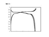
- FIG. 1 shows charge and discharge curves at the time of initial charge and discharge, at 50 cycles, and at 100 cycles in the lithium ion secondary battery of Example I in an overlapping manner.
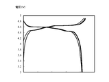
- FIG. 2 shows charge and discharge curves of the lithium ion secondary battery of Example II in an initial charge and discharge cycle, at 10 cycles, at 20 cycles, and at 50 cycles.
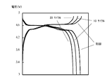
- FIG. 3 shows the charge-discharge curves of the lithium ion secondary battery of Example III in an initial charge / discharge cycle, 10 cycles, 20 cycles, and 50 cycles in an overlapping manner.
- FIG. 4 shows the charge-discharge curves of the lithium ion secondary battery of Comparative Example I at initial charge / discharge, at 10 cycles, and at 20 cycles in an overlapping manner.
- the lithium ion secondary batteries of Examples I to III exhibited remarkably excellent capacity retention as compared with the lithium ion secondary battery of Comparative Example I. Further, as shown in FIGS. 1 to 3, in the lithium ion secondary batteries of Examples I to III, almost no fluctuation of the charge / discharge curve was observed even after repeated cycles. It was supported that the lithium ion secondary battery equipped with the electrolytic solution of the present invention exhibits extremely excellent durability against charge and discharge cycles at a voltage of 4.5 V or more.
Landscapes
- Chemical & Material Sciences (AREA)
- Chemical Kinetics & Catalysis (AREA)
- Electrochemistry (AREA)
- Engineering & Computer Science (AREA)
- Power Engineering (AREA)
- General Chemical & Material Sciences (AREA)
- Manufacturing & Machinery (AREA)
- General Physics & Mathematics (AREA)
- Condensed Matter Physics & Semiconductors (AREA)
- Inorganic Chemistry (AREA)
- Physics & Mathematics (AREA)
- Microelectronics & Electronic Packaging (AREA)
- Materials Engineering (AREA)
- Secondary Cells (AREA)
- Electric Double-Layer Capacitors Or The Like (AREA)
- Cell Electrode Carriers And Collectors (AREA)
- Battery Electrode And Active Subsutance (AREA)
Abstract
下記一般式(1-1)で表される鎖状カーボネート、下記一般式(1-2)で表されるエステル、又は、下記一般式(1-3)で表されるリン酸エステルが、 アルカリ金属、アルカリ土類金属又はアルミニウムをカチオンとし、下記一般式(2)で表される化学構造をアニオンとする金属塩に対し、 モル比1~3で含まれること特徴とする電解液。 R10OCOOR11 一般式(1-1) R12COOR13 一般式(1-2) OP(OR14)(OR15)(OR16) 一般式(1-3) (R21X21)(R22SO2)N 一般式(2)
Description
本発明は、二次電池等の蓄電装置に用いられる電解液に関する。
一般に、二次電池等の蓄電装置は、主な構成要素として、正極、負極及び電解液を備える。そして、電解液には、適切な電解質が適切な濃度範囲で添加されている。例えば、リチウムイオン二次電池の電解液には、LiClO4、LiAsF6、LiPF6、LiBF4、CF3SO3Li、(CF3SO2)2NLi等のリチウム塩が電解質として添加されるのが一般的であり、ここで、電解液におけるリチウム塩の濃度は、概ね1mol/Lとされるのが一般的である。
また、電解液に用いられる有機溶媒には、電解質を好適に溶解させるために、エチレンカーボネートやプロピレンカーボネート等の環状カーボネートを約30体積%以上で混合して用いるのが一般的である。
実際に、特許文献1には、エチレンカーボネートを33体積%含む混合有機溶媒を用い、かつ、LiPF6を1mol/Lの濃度で含む電解液を用いたリチウムイオン二次電池が開示されている。また、特許文献2には、エチレンカーボネート及びプロピレンカーボネートを66体積%含む混合有機溶媒を用い、かつ、(CF3SO2)2NLiを1mol/Lの濃度で含む電解液を用いたリチウムイオン二次電池が開示されている。
特許文献1~2に記載のとおり、従来、リチウムイオン二次電池に用いられる電解液においては、エチレンカーボネートやプロピレンカーボネートを約30体積%以上で含有する混合有機溶媒を用い、かつ、リチウム塩を概ね1mol/Lの濃度で含むことが技術常識となっていた。
さて、産業界からは、蓄電装置の高出力化が求められている。蓄電装置の高出力化方法としては、例えば、正極活物質及び負極活物質を高容量なものに変更すること、電極を高密度とすること、デバイスの省容量化などが挙げられる。これらの方法については、多くの研究者により、改良が重ねられてきた。
また、蓄電装置の高出力化方法として、高電位で蓄電装置を作動させることが挙げられる。しかしながら、現状の蓄電装置の作動電位は、蓄電装置の構成材料が耐え得る限界付近である。したがって、より高電位で蓄電装置を作動させるためには、構成材料の抜本的な改良が必要である。
例えば、特許文献3には、電解質としてLiPF6、有機溶媒としてフルオロエーテル及びエチレンカーボネート若しくはプロピレンカーボネートを用いた特定の濃度の電解液が記載されており、当該電解液を具備する二次電池が4.5Vとの高電位条件で作動させた場合に優れた容量維持率を示したことが記載されている。
本発明は、かかる事情に鑑みて為されたものであり、高電位で使用可能な、新たな電解液を提供することを目的とする。
本発明者は、従来の技術常識にとらわれることなく、数多くの試行錯誤を重ねながら鋭意検討を行った。その結果、本発明者は、特定の化学構造の有機溶媒に、特定の化学構造の金属塩が、著しく高い濃度で溶解し得ることを知見した。さらに、本発明者は、特定の化学構造の有機溶媒が、特定の化学構造の金属塩に対し、特定のモル比で存在する電解液が、高電位で作動する二次電池等の蓄電装置に好適に使用できることを知見した。これらの知見に基づき、本発明者は、本発明を完成するに至った。
本発明の電解液は、
下記一般式(1-1)で表される鎖状カーボネート、下記一般式(1-2)で表されるエステル、又は、下記一般式(1-3)で表されるリン酸エステルが、
アルカリ金属、アルカリ土類金属又はアルミニウムをカチオンとし、下記一般式(2)で表される化学構造をアニオンとする金属塩に対し、
モル比1~3で含まれること特徴とする。
下記一般式(1-1)で表される鎖状カーボネート、下記一般式(1-2)で表されるエステル、又は、下記一般式(1-3)で表されるリン酸エステルが、
アルカリ金属、アルカリ土類金属又はアルミニウムをカチオンとし、下記一般式(2)で表される化学構造をアニオンとする金属塩に対し、
モル比1~3で含まれること特徴とする。
R10OCOOR11 一般式(1-1)
R12COOR13 一般式(1-2)
OP(OR14)(OR15)(OR16) 一般式(1-3)
(R10、R11、R12、R13、R14、R15、R16は、それぞれ独立に、鎖状アルキルであるCnHaFbClcBrdIe、又は、環状アルキルを化学構造に含むCmHfFgClhBriIjのいずれかから選択される。nは1以上の整数、mは3以上の整数、a、b、c、d、e、f、g、h、i、jはそれぞれ独立に0以上の整数であり、2n+1=a+b+c+d+e、2m=f+g+h+i+jを満たす。
ただし、R10若しくはR11はb≧1若しくはg≧1、R12若しくはR13はb≧1若しくはg≧1、R14、R15若しくはR16はb≧1若しくはg≧1を満たす。)
(R21X21)(R22SO2)N 一般式(2)
(R21は、水素、ハロゲン、置換基で置換されていても良いアルキル基、置換基で置換されていても良いシクロアルキル基、置換基で置換されていても良い不飽和アルキル基、置換基で置換されていても良い不飽和シクロアルキル基、置換基で置換されていても良い芳香族基、置換基で置換されていても良い複素環基、置換基で置換されていても良いアルコキシ基、置換基で置換されていても良い不飽和アルコキシ基、置換基で置換されていても良いチオアルコキシ基、置換基で置換されていても良い不飽和チオアルコキシ基、CN、SCN、OCNから選択される。
R22は、水素、ハロゲン、置換基で置換されていても良いアルキル基、置換基で置換されていても良いシクロアルキル基、置換基で置換されていても良い不飽和アルキル基、置換基で置換されていても良い不飽和シクロアルキル基、置換基で置換されていても良い芳香族基、置換基で置換されていても良い複素環基、置換基で置換されていても良いアルコキシ基、置換基で置換されていても良い不飽和アルコキシ基、置換基で置換されていても良いチオアルコキシ基、置換基で置換されていても良い不飽和チオアルコキシ基、CN、SCN、OCNから選択される。
また、R21とR22は、互いに結合して環を形成しても良い。
X21は、SO2、C=O、C=S、RaP=O、RbP=S、S=O、Si=Oから選択される。
Ra、Rbは、それぞれ独立に、水素、ハロゲン、置換基で置換されていても良いアルキル基、置換基で置換されていても良いシクロアルキル基、置換基で置換されていても良い不飽和アルキル基、置換基で置換されていても良い不飽和シクロアルキル基、置換基で置換されていても良い芳香族基、置換基で置換されていても良い複素環基、置換基で置換されていても良いアルコキシ基、置換基で置換されていても良い不飽和アルコキシ基、置換基で置換されていても良いチオアルコキシ基、置換基で置換されていても良い不飽和チオアルコキシ基、OH、SH、CN、SCN、OCNから選択される。
また、Ra、Rbは、R21又はR22と結合して環を形成しても良い。)
本発明の新規な電解液は、二次電池等の蓄電装置の電解液として好適である。
以下に、本発明を実施するための形態を説明する。なお、特に断らない限り、本明細書に記載された数値範囲「a~b」は、下限a及び上限bをその範囲に含む。そして、これらの上限値及び下限値、ならびに実施例中に列記した数値も含めてそれらを任意に組み合わせることで数値範囲を構成し得る。さらに数値範囲内から任意に選択した数値を上限、下限の数値とすることができる。
本発明の電解液は、
下記一般式(1-1)で表される鎖状カーボネート、下記一般式(1-2)で表されるエステル、又は、下記一般式(1-3)で表されるリン酸エステルが、
アルカリ金属、アルカリ土類金属又はアルミニウムをカチオンとし、下記一般式(2)で表される化学構造をアニオンとする金属塩に対し、
モル比1~3で含まれること特徴とする。
下記一般式(1-1)で表される鎖状カーボネート、下記一般式(1-2)で表されるエステル、又は、下記一般式(1-3)で表されるリン酸エステルが、
アルカリ金属、アルカリ土類金属又はアルミニウムをカチオンとし、下記一般式(2)で表される化学構造をアニオンとする金属塩に対し、
モル比1~3で含まれること特徴とする。
R10OCOOR11 一般式(1-1)
R12COOR13 一般式(1-2)
OP(OR14)(OR15)(OR16) 一般式(1-3)
(R10、R11、R12、R13、R14、R15、R16は、それぞれ独立に、鎖状アルキルであるCnHaFbClcBrdIe、又は、環状アルキルを化学構造に含むCmHfFgClhBriIjのいずれかから選択される。nは1以上の整数、mは3以上の整数、a、b、c、d、e、f、g、h、i、jはそれぞれ独立に0以上の整数であり、2n+1=a+b+c+d+e、2m=f+g+h+i+jを満たす。
ただし、R10若しくはR11はb≧1若しくはg≧1、R12若しくはR13はb≧1若しくはg≧1、R14、R15若しくはR16はb≧1若しくはg≧1を満たす。)
R12COOR13 一般式(1-2)
OP(OR14)(OR15)(OR16) 一般式(1-3)
(R10、R11、R12、R13、R14、R15、R16は、それぞれ独立に、鎖状アルキルであるCnHaFbClcBrdIe、又は、環状アルキルを化学構造に含むCmHfFgClhBriIjのいずれかから選択される。nは1以上の整数、mは3以上の整数、a、b、c、d、e、f、g、h、i、jはそれぞれ独立に0以上の整数であり、2n+1=a+b+c+d+e、2m=f+g+h+i+jを満たす。
ただし、R10若しくはR11はb≧1若しくはg≧1、R12若しくはR13はb≧1若しくはg≧1、R14、R15若しくはR16はb≧1若しくはg≧1を満たす。)
(R21X21)(R22SO2)N 一般式(2)
(R21は、水素、ハロゲン、置換基で置換されていても良いアルキル基、置換基で置換されていても良いシクロアルキル基、置換基で置換されていても良い不飽和アルキル基、置換基で置換されていても良い不飽和シクロアルキル基、置換基で置換されていても良い芳香族基、置換基で置換されていても良い複素環基、置換基で置換されていても良いアルコキシ基、置換基で置換されていても良い不飽和アルコキシ基、置換基で置換されていても良いチオアルコキシ基、置換基で置換されていても良い不飽和チオアルコキシ基、CN、SCN、OCNから選択される。
R22は、水素、ハロゲン、置換基で置換されていても良いアルキル基、置換基で置換されていても良いシクロアルキル基、置換基で置換されていても良い不飽和アルキル基、置換基で置換されていても良い不飽和シクロアルキル基、置換基で置換されていても良い芳香族基、置換基で置換されていても良い複素環基、置換基で置換されていても良いアルコキシ基、置換基で置換されていても良い不飽和アルコキシ基、置換基で置換されていても良いチオアルコキシ基、置換基で置換されていても良い不飽和チオアルコキシ基、CN、SCN、OCNから選択される。
また、R21とR22は、互いに結合して環を形成しても良い。
X21は、SO2、C=O、C=S、RaP=O、RbP=S、S=O、Si=Oから選択される。
Ra、Rbは、それぞれ独立に、水素、ハロゲン、置換基で置換されていても良いアルキル基、置換基で置換されていても良いシクロアルキル基、置換基で置換されていても良い不飽和アルキル基、置換基で置換されていても良い不飽和シクロアルキル基、置換基で置換されていても良い芳香族基、置換基で置換されていても良い複素環基、置換基で置換されていても良いアルコキシ基、置換基で置換されていても良い不飽和アルコキシ基、置換基で置換されていても良いチオアルコキシ基、置換基で置換されていても良い不飽和チオアルコキシ基、OH、SH、CN、SCN、OCNから選択される。
また、Ra、Rbは、R21又はR22と結合して環を形成しても良い。)
(R21は、水素、ハロゲン、置換基で置換されていても良いアルキル基、置換基で置換されていても良いシクロアルキル基、置換基で置換されていても良い不飽和アルキル基、置換基で置換されていても良い不飽和シクロアルキル基、置換基で置換されていても良い芳香族基、置換基で置換されていても良い複素環基、置換基で置換されていても良いアルコキシ基、置換基で置換されていても良い不飽和アルコキシ基、置換基で置換されていても良いチオアルコキシ基、置換基で置換されていても良い不飽和チオアルコキシ基、CN、SCN、OCNから選択される。
R22は、水素、ハロゲン、置換基で置換されていても良いアルキル基、置換基で置換されていても良いシクロアルキル基、置換基で置換されていても良い不飽和アルキル基、置換基で置換されていても良い不飽和シクロアルキル基、置換基で置換されていても良い芳香族基、置換基で置換されていても良い複素環基、置換基で置換されていても良いアルコキシ基、置換基で置換されていても良い不飽和アルコキシ基、置換基で置換されていても良いチオアルコキシ基、置換基で置換されていても良い不飽和チオアルコキシ基、CN、SCN、OCNから選択される。
また、R21とR22は、互いに結合して環を形成しても良い。
X21は、SO2、C=O、C=S、RaP=O、RbP=S、S=O、Si=Oから選択される。
Ra、Rbは、それぞれ独立に、水素、ハロゲン、置換基で置換されていても良いアルキル基、置換基で置換されていても良いシクロアルキル基、置換基で置換されていても良い不飽和アルキル基、置換基で置換されていても良い不飽和シクロアルキル基、置換基で置換されていても良い芳香族基、置換基で置換されていても良い複素環基、置換基で置換されていても良いアルコキシ基、置換基で置換されていても良い不飽和アルコキシ基、置換基で置換されていても良いチオアルコキシ基、置換基で置換されていても良い不飽和チオアルコキシ基、OH、SH、CN、SCN、OCNから選択される。
また、Ra、Rbは、R21又はR22と結合して環を形成しても良い。)
通常の電解液では、多数の溶媒分子中に、少量の電解質が点在している状態である。この状態においては、電解質と配位している溶媒とともに、電解質と非配位の溶媒が多数存在する。
本発明の電解液では、一般式(1-1)で表される鎖状カーボネート、一般式(1-2)で表されるエステル、又は、一般式(1-3)で表されるリン酸エステル(以下、これらの溶媒をまとめて「本発明の有機溶媒」ということがある。)が、金属塩に対し、モル比1~3で含まれる。本発明の電解液においては、一般式(1-1)で表される鎖状カーボネート、一般式(1-2)で表されるエステル、又は、一般式(1-3)で表されるリン酸エステルのほぼすべてが、金属塩と配位している状態(以下、この状態を「クラスター」ということがある。)にあると考えられる。
本発明の有機溶媒は、いずれも化学構造にフッ素を有している。フッ素を有する点で、電解液の高電位に対する耐性が向上していると考えられる。加えて、電解液をより難燃性にしていると考えられる。
また、本発明の有機溶媒は、いずれもO-C=O若しくはO-P=Oなる化学構造を有している。かかる化学構造が有する酸素の非共有電子対が、前記金属塩との好適な配位状態を実現させていると考えられる。
また、本発明の電解液において、上記金属塩の上記一般式(2)の化学構造には、SO2が含まれている。後に詳細に説明するように、この化学構造が、高電位に対する電解液の劣化防止に寄与していると考えられる。
一般式(1-1)、一般式(1-2)又は一般式(1-3)において、R10、R11、R12、R13、R14、R15、R16は、それぞれ独立に、鎖状アルキルであるCnHaFb、又は、環状アルキルを化学構造に含むCmHfFgのいずれかから選択されるのが好ましい。ここで、nは1以上の整数、mは3以上の整数、a、b、f、gはそれぞれ独立に0以上の整数であり、2n+1=a+b、2m=f+gを満たす。
一般式(1-1)、一般式(1-2)又は一般式(1-3)において、R10若しくはR11はb≧2若しくはg≧2、R12若しくはR13はb≧2若しくはg≧2、R14、R15若しくはR16はb≧2若しくはg≧2を満たすのが好ましい。
一般式(1-1)、一般式(1-2)又は一般式(1-3)に関するnは、1~6の整数であるのが好ましく、1~4の整数がより好ましく、1~2の整数が特に好ましい。mは3~8の整数が好ましく、4~7の整数がより好ましく、5~6の整数が特に好ましい。
本発明の有機溶媒のうちでは、一般式(1-1)で表される鎖状カーボネートが好ましい。
一般式(1-1)で表される鎖状カーボネートとしては、フルオロメチルメチルカーボネート、ジフルオロメチルメチルカーボネート、トリフルオロメチルメチルカーボネート、ビス(フルオロメチル)カーボネート、ビス(ジフルオロ)メチルカーボネート、ビス(トリフルオロメチル)カーボネート、フルオロメチルジフルオロメチルカーボネート、フルオロメチルトリフルオロメチルカーボネート、ジフルオロメチルトリフルオロメチルカーボネート、2-フルオロエチルメチルカーボネート、2,2-ジフルオロエチルメチルカーボネート、2,2,2-トリフルオロエチルメチルカーボネート、ペンタフルオロエチルメチルカーボネート、エチルトリフルオロメチルカーボネート、フルオロエチルエチルカーボネート、トリフルオロエチルエチルカーボネート、ビス(2,2,2-トリフルオロエチル)カーボネートが特に好ましい。
一般式(1-2)で表されるエステルとしては、フルオロ酢酸メチル、フルオロ酢酸エチル、ジフルオロ酢酸メチル、ジフルオロ酢酸エチル、トリフルオロ酢酸メチル、トリフルオロ酢酸エチル、酢酸2-フルオロエチル、酢酸2,2-ジフルオロエチル、酢酸2,2,2-トリフルオロエチル、フルオロ酢酸2-フルオロエチル、フルオロ酢酸2,2-ジフルオロエチル、フルオロ酢酸2,2,2-トリフルオロエチル、ジフルオロ酢酸2-フルオロエチル、ジフルオロ酢酸2,2-ジフルオロエチル、ジフルオロ酢酸2,2,2-トリフルオロエチル、トリフルオロ酢酸2-フルオロエチル、トリフルオロ酢酸2,2-ジフルオロエチル、トリフルオロ酢酸2,2,2-トリフルオロエチル、フルオロプロピオン酸メチル、フルオロプロピオン酸エチル、ジフルオロプロピオン酸メチル、ジフルオロプロピオン酸エチル、トリフルオロプロピオン酸メチル、トリフルオロプロピオン酸エチル、テトラフルオロプロピオン酸メチル、テトラフルオロプロピオン酸エチル、ペンタフルオロプロピオン酸メチル、ペンタフルオロプロピオン酸エチル、プロピオン酸2-フルオロエチル、プロピオン酸2,2-ジフルオロエチル、プロピオン酸2,2,2-トリフルオロエチル、フルオロプロピオン酸2-フルオロエチル、フルオロプロピオン酸2,2-ジフルオロエチル、フルオロプロピオン酸2,2,2-トリフルオロエチル、ジフルオロプロピオン酸2-フルオロエチル、ジフルオロプロピオン酸2,2-ジフルオロエチル、ジフルオロプロピオン酸2,2,2-トリフルオロエチル、トリフルオロプロピオン酸2-フルオロエチル、トリフルオロプロピオン酸2,2-ジフルオロエチル、トリフルオロプロピオン酸2,2,2-トリフルオロエチル、テトラフルオロプロピオン酸2-フルオロエチル、テトラフルオロプロピオン酸2,2-ジフルオロエチル、テトラフルオロプロピオン酸2,2,2-トリフルオロエチル、ペンタフルオロプロピオン酸2-フルオロエチル、ペンタフルオロプロピオン酸2,2-ジフルオロエチル、ペンタフルオロプロピオン酸2,2,2-トリフルオロエチルが特に好ましい。
一般式(1-3)で表されるリン酸エステルとしては、リン酸ジメチル2-フルオロエチルエステル、リン酸ジメチル2,2-ジフルオロエチルエステル、リン酸ジメチル2,2,2-トリフルオロエチルエステル、リン酸ジエチル2-フルオロエチルエステル、リン酸ジエチル2,2-ジフルオロエチルエステル、リン酸ジエチル2,2,2-トリフルオロエチルエステル、リン酸メチルビス(2-フルオロエチル)エステル、リン酸メチルビス(2,2-ジフルオロエチル)エステル、リン酸メチルビス(2,2,2-トリフルオロエチル)エステル、リン酸エチルビス(2-フルオロエチル)エステル、リン酸エチルビス(2,2-ジフルオロエチル)エステル、リン酸エチルビス(2,2,2-トリフルオロエチル)エステル、リン酸トリス(2-フルオロエチル)エステル、リン酸トリス(2,2-ジフルオロエチル)エステル、リン酸トリス(2,2,2-トリフルオロエチル)エステルが特に好ましい。
以上で説明した一般式(1-1)で表される鎖状カーボネート、一般式(1-2)で表されるエステル、一般式(1-3)で表されるリン酸エステルは、それぞれ単独で電解液に用いても良いし、複数を併用しても良い。
本発明の電解液における金属塩のカチオンとしては、リチウム、ナトリウム、カリウムなどのアルカリ金属、ベリリウム、マグネシウム、カルシウム、ストロンチウム、バリウムなどのアルカリ土類金属、及びアルミニウムを挙げることができる。金属塩のカチオンは、電解液を使用する電池の電荷担体と同一の金属イオンであるのが好ましい。例えば、本発明の電解液をリチウムイオン二次電池用の電解液として使用するのであれば、金属塩のカチオンはリチウムが好ましい。
上記一般式(2)で表される化学構造における、「置換基で置換されていても良い」との文言について説明する。例えば「置換基で置換されていても良いアルキル基」であれば、アルキル基の水素の一つ若しくは複数が置換基で置換されているアルキル基、又は、特段の置換基を有さないアルキル基を意味する。
「置換基で置換されていても良い」との文言における置換基としては、アルキル基、アルケニル基、アルキニル基、シクロアルキル基、不飽和シクロアルキル基、芳香族基、複素環基、ハロゲン、OH、SH、CN、SCN、OCN、ニトロ基、アルコキシ基、不飽和アルコキシ基、アミノ基、アルキルアミノ基、ジアルキルアミノ基、アリールオキシ基、アシル基、アルコキシカルボニル基、アシルオキシ基、アリールオキシカルボニル基、アシルアミノ基、アルコキシカルボニルアミノ基、アリールオキシカルボニルアミノ基、スルホニルアミノ基、スルファモイル基、カルバモイル基、アルキルチオ基、アリールチオ基、スルホニル基、スルフィニル基、ウレイド基、リン酸アミド基、スルホ基、カルボキシル基、ヒドロキサム酸基、スルフィノ基、ヒドラジノ基、イミノ基、シリル基等が挙げられる。これらの置換基はさらに置換されてもよい。また置換基が2つ以上ある場合、置換基は同一でも異なっていてもよい。
前記金属塩のアニオンの化学構造は、下記一般式(2-1)で表される化学構造が好ましい。
(R23X22)(R24SO2)N 一般式(2-1)
(R23、R24は、それぞれ独立に、CnHaFbClcBrdIe(CN)f(SCN)g(OCN)hである。
n、a、b、c、d、e、f、g、hはそれぞれ独立に0以上の整数であり、2n+1=a+b+c+d+e+f+g+hを満たす。
また、R23とR24は、互いに結合して環を形成しても良く、その場合は、2n=a+b+c+d+e+f+g+hを満たす。
X22は、SO2、C=O、C=S、RcP=O、RdP=S、S=O、Si=Oから選択される。
Rc、Rdは、それぞれ独立に、水素、ハロゲン、置換基で置換されていても良いアルキル基、置換基で置換されていても良いシクロアルキル基、置換基で置換されていても良い不飽和アルキル基、置換基で置換されていても良い不飽和シクロアルキル基、置換基で置換されていても良い芳香族基、置換基で置換されていても良い複素環基、置換基で置換されていても良いアルコキシ基、置換基で置換されていても良い不飽和アルコキシ基、置換基で置換されていても良いチオアルコキシ基、置換基で置換されていても良い不飽和チオアルコキシ基、OH、SH、CN、SCN、OCNから選択される。
また、Rc、Rdは、R23又はR24と結合して環を形成しても良い。)
上記一般式(2-1)で表される化学構造における、「置換基で置換されていても良い」との文言の意味は、上記一般式(2)で説明したのと同義である。
上記一般式(2-1)で表される化学構造において、nは0~6の整数が好ましく、0~4の整数がより好ましく、0~2の整数が特に好ましい。なお、上記一般式(2-1)で表される化学構造の、R23とR24が結合して環を形成している場合には、nは1~8の整数が好ましく、1~7の整数がより好ましく、1~3の整数が特に好ましい。
前記金属塩のアニオンの化学構造は、下記一般式(2-2)で表されるものがさらに好ましい。
(R25SO2)(R26SO2)N 一般式(2-2)
(R25、R26は、それぞれ独立に、CnHaFbClcBrdIeである。
n、a、b、c、d、eはそれぞれ独立に0以上の整数であり、2n+1=a+b+c+d+eを満たす。
また、R25とR26は、互いに結合して環を形成しても良く、その場合は、2n=a+b+c+d+eを満たす。)
(R25、R26は、それぞれ独立に、CnHaFbClcBrdIeである。
n、a、b、c、d、eはそれぞれ独立に0以上の整数であり、2n+1=a+b+c+d+eを満たす。
また、R25とR26は、互いに結合して環を形成しても良く、その場合は、2n=a+b+c+d+eを満たす。)
上記一般式(2-2)で表される化学構造において、nは0~6の整数が好ましく、0~4の整数がより好ましく、0~2の整数が特に好ましい。なお、上記一般式(2-2)で表される化学構造の、R25とR26が結合して環を形成している場合には、nは1~8の整数が好ましく、1~7の整数がより好ましく、1~3の整数が特に好ましい。
また、上記一般式(2-2)で表される化学構造において、aが0のもの、cが0のもの、dが0のもの、eが0のものが好ましい。
金属塩は、(CF3SO2)2NLi(以下、「LiTFSA」ということがある。)、(FSO2)2NLi(以下、「LiFSA」ということがある。)、(C2F5SO2)2NLi、FSO2(CF3SO2)NLi、(SO2CF2CF2SO2)NLi、(SO2CF2CF2CF2SO2)NLi、FSO2(CH3SO2)NLi、FSO2(C2F5SO2)NLi、又はFSO2(C2H5SO2)NLiが特に好ましい。
本発明の金属塩は、以上で説明したカチオンとアニオンをそれぞれ適切な数で組み合わせたものを採用すれば良い。本発明の電解液における金属塩は1種類を採用しても良いし、複数種を併用しても良い。
本発明の電解液には、上記金属塩以外に、蓄電装置の電解液に使用可能である他の電解質が含まれていてもよい。本発明の電解液には、本発明の電解液に含まれる全電解質に対し、上記金属塩が50質量%以上で含まれるのが好ましく、70質量%以上で含まれるのがより好ましく、90質量%以上で含まれるのがさらに好ましい。
本発明の電解液は、一般式(1-1)で表される鎖状カーボネート、一般式(1-2)で表されるエステル、又は、一般式(1-3)で表されるリン酸エステルが前記金属塩に対しモル比1~3で含まれる。上記モル比は、1.2~2.5の範囲内がより好ましい。なお、従来の電解液は、有機溶媒と電解質とのモル比が概ね10程度である。
本発明の電解液は、その振動分光スペクトルにおいて、本発明の有機溶媒由来のピーク強度につき、当該本発明の有機溶媒本来のピークの強度をIoとし、本発明の有機溶媒本来のピークがシフトしたピーク(以下、「シフトピーク」ということがある。)の強度をIsとした場合、Is>Ioとなって観察される場合がある。
ここで、「有機溶媒本来のピーク」とは、有機溶媒のみを振動分光測定した場合のピーク位置(波数)に、観察されるピークを意味する。有機溶媒本来のピークの強度Ioの値と、シフトピークの強度Isの値は、振動分光スペクトルにおける各ピークのベースラインからの高さ又は面積である。
前述したように、本発明の電解液においては、本発明の有機溶媒のほぼすべてが、金属塩と配位してクラスターを形成していると考えられる。
クラスターを形成している有機溶媒と、クラスターの形成に関与していない有機溶媒とは、それぞれの存在環境が異なる。そのため、振動分光測定において、クラスターを形成している有機溶媒由来のピークは、クラスターの形成に関与していない有機溶媒由来のピーク(すなわち有機溶媒本来のピーク)の観察される波数から、高波数側又は低波数側にシフトして観察される。つまり、シフトピークはクラスターを形成している有機溶媒のピークに相当する。
振動分光スペクトルとしては、IRスペクトル又はラマンスペクトルを挙げることができる。IRスペクトルの測定方法としては、ヌジョール法、液膜法などの透過測定方法、ATR法などの反射測定方法を挙げることができる。IRスペクトル又はラマンスペクトルのいずれを選択するかについては、本発明の電解液の振動分光スペクトルにおいて、IsとIoの関係を判断しやすいスペクトルの方を選択すれば良い。なお、振動分光測定は、大気中の水分の影響を軽減又は無視できる条件で行うのがよい。例えば、ドライルーム、グローブボックスなどの低湿度又は無湿度条件下でIR測定を行うこと、又は、電解液を密閉容器に入れたままの状態でラマン測定を行うのがよい。
有機溶媒の波数とその帰属につき、公知のデータを参考としてもよい。参考文献として、日本分光学会測定法シリーズ17 ラマン分光法、濱口宏夫、平川暁子、学会出版センター、231~249頁を挙げる。また、コンピュータを用いた計算でも、Io及びIsの算出に有用と考えられる鎖状カーボネートの波数と、鎖状カーボネートと金属塩が配位した場合の波数シフトを予測することができる。例えば、Gaussian09(登録商標、ガウシアン社)を用い、密度汎関数をB3LYP、基底関数を6-311G++(d,p)として計算すればよい。当業者は、公知のデータ、コンピュータでの計算結果を参考にして、有機溶媒のピークを選定し、Io及びIsを算出することができる。
また、本発明の電解液を振動分光測定に供し得られる振動分光スペクトルチャートにおいて、上記一般式(2)で表される化学構造に由来するピークが低波数側又は高波数側にシフトするのが観察される場合がある。振動分光スペクトルとしては、IRスペクトル又はラマンスペクトルを挙げることができる。
本発明の電解液は高濃度で金属塩を含むため、金属塩を構成するカチオンとアニオンとが強く相互作用して、金属塩がCIP(Contact ion pairs)状態やAGG(aggregate)状態を主に形成していると推察される。そして、かかる状態の変化が振動分光スペクトルチャートにおける上記一般式(2)で表される化学構造に由来するピークのシフトとして観察される。
本発明の電解液は、従来の電解液と比較して、金属塩の存在割合が高いといえる。そうすると、本発明の電解液は、従来の電解液と比較して、金属塩と有機溶媒の存在環境が異なっているといえる。そのため、本発明の電解液を用いた二次電池等の蓄電装置においては、電解液中の金属イオン輸送速度の向上、電極と電解液の界面における反応速度の向上、二次電池のハイレート充放電時に起こる電解液の金属塩濃度の偏在の緩和、電極界面における電解液の保液性の向上、電極界面で電解液が不足するいわゆる液枯れ状態の抑制、電気二重層の容量増大などが期待できる。さらに、本発明の電解液においては、電解液に含まれる有機溶媒の蒸気圧が低くなる。その結果として、本発明の電解液からの有機溶媒の揮発が低減できる。
本発明の電解液は金属塩のカチオンを高濃度で含有する。このため、本発明の電解液中において、隣り合うカチオン間の距離は極めて近い。そして、二次電池の充放電時にリチウムイオン等のカチオンが正極と負極との間を移動する際には、移動先の電極に直近のカチオンが先ず当該電極に供給される。そして、供給された当該カチオンがあった場所には、当該カチオンに隣り合う他のカチオンが移動する。つまり、本発明の電解液中においては、隣り合うカチオンが供給対象となる電極に向けて順番に一つずつ位置を変えるという、ドミノ倒し様の現象が生じていると予想される。このため、充放電時の電解液中カチオンの移動距離は短く、その分だけカチオンの移動速度が高いと考えられる。このことに起因して、本発明の電解液は高粘度であってもイオン伝導性を有すると考えられる。
また後述の通り、本発明の電解液を具備する二次電池は、電極/電解液界面に、低抵抗かつカチオン含有率の高いSEI皮膜を金属塩由来物で形成することで、電極/電解液界面において可逆的かつ高速な反応を可能にすると考えられる。
また後述の通り、本発明の電解液を具備する二次電池は、電極/電解液界面に、低抵抗かつカチオン含有率の高いSEI皮膜を金属塩由来物で形成することで、電極/電解液界面において可逆的かつ高速な反応を可能にすると考えられる。
また、本発明の電解液には、本発明の趣旨を逸脱しない範囲で、公知の他の溶媒を加えてもよい。例えば、本発明の電解液に、当該電解液で必須とする溶媒よりも分解しやすい溶媒が含有していても、その量が一定程度であれば、当該溶媒の分解の頻度は高くない。そのため、そのような本発明の電解液を具備する二次電池は、高電位条件下であっても、安定に作動し得る。
他の溶媒を具体的に例示すると、アセトニトリル、プロピオニトリル、アクリロニトリル、マロノニトリル等のニトリル類、1,2-ジメトキシエタン、1,2-ジエトキシエタン、テトラヒドロフラン、1,2-ジオキサン、1,3-ジオキサン、1,4-ジオキサン、2,2-ジメチル-1,3-ジオキソラン、2-メチルテトラヒドロピラン、2-メチルテトラヒドロフラン、クラウンエーテル等のエーテル類、エチレンカーボネート、プロピレンカーボネート、ジメチルカーボネート、ジエチルカーボネート、エチルメチルカーボネート等のカーボネート類、ホルムアミド、N,N-ジメチルホルムアミド、N,N-ジメチルアセトアミド、N-メチルピロリドン等のアミド類、イソプロピルイソシアネート、n-プロピルイソシアネート、クロロメチルイソシアネート等のイソシアネート類、酢酸メチル、酢酸エチル、酢酸プロピル、酢酸ブチル、プロピオン酸メチル、蟻酸メチル、蟻酸エチル、酢酸ビニル、メチルアクリレート、メチルメタクリレート等のエステル類、グリシジルメチルエーテル、エポキシブタン、2-エチルオキシラン等のエポキシ類、オキサゾール、2-エチルオキサゾール、オキサゾリン、2-メチル-2-オキサゾリン等のオキサゾール類、アセトン、メチルエチルケトン、メチルイソブチルケトン等のケトン類、無水酢酸、無水プロピオン酸等の酸無水物、ジメチルスルホン、スルホラン等のスルホン類、ジメチルスルホキシド等のスルホキシド類、1-ニトロプロパン、2-ニトロプロパン等のニトロ類、フラン、フルフラール等のフラン類、γ-ブチロラクトン、γ-バレロラクトン、δ-バレロラクトン等の環状エステル類、チオフェン、ピリジン等の芳香族複素環類、テトラヒドロ-4-ピロン、1-メチルピロリジン、N-メチルモルフォリン等の複素環類、リン酸トリメチル、リン酸トリエチル等のリン酸エステル類を挙げることができる。
本発明の電解液には、本発明の電解液に含まれる全溶媒に対し、一般式(1-1)で表される鎖状カーボネート、一般式(1-2)で表されるエステル、又は、一般式(1-3)で表されるリン酸エステルが、例えば50体積%以上、60体積%以上、70体積%以上、80体積%以上、90体積%以上、又は95体積%以上で含まれるのが好ましい。また、本発明の電解液には、本発明の電解液に含まれる全溶媒に対し、一般式(1-1)で表される鎖状カーボネート、一般式(1-2)で表されるエステル、又は、一般式(1-3)で表されるリン酸エステルが、例えば50モル%以上、60モル%以上、70モル%以上、80モル%以上、90モル%以上、又は95モル%以上で含まれるのが好ましい。
本発明の電解液に、炭化水素からなる有機溶媒を加えると、電解液の粘度が低くなるとの効果を期待できる。
上記炭化水素からなる有機溶媒としては、具体的にベンゼン、トルエン、エチルベンゼン、o-キシレン、m-キシレン、p-キシレン、1-メチルナフタレン、ヘキサン、ヘプタン、シクロヘキサンを例示することができる。
また、本発明の電解液には、難燃性の溶媒を加えることができる。難燃性の溶媒を本発明の電解液に加えることにより、本発明の電解液の安全度をさらに高めることができる。難燃性の溶媒としては、四塩化炭素、テトラクロロエタン、ハイドロフルオロエーテルなどのハロゲン系溶媒、リン酸トリメチル、リン酸トリエチルなどのリン酸誘導体を例示することができる。
本発明の電解液をポリマーや無機フィラーと混合し混合物とすると、当該混合物が電解液を封じ込め、擬似固体電解質となる。擬似固体電解質を電池の電解液として用いることで、電池における電解液の液漏れを抑制することができる。
上記ポリマーとしては、リチウムイオン二次電池などの電池に使用されるポリマーや一般的な化学架橋したポリマーを採用することができる。特に、ポリフッ化ビニリデンやポリヘキサフルオロプロピレンなど電解液を吸収しゲル化し得るポリマーや、ポリエチレンオキシドなどのポリマーにイオン導電性基を導入したものが好適である。
具体的なポリマーとしては、ポリメチルアクリレート、ポリメチルメタクリレート、ポリエチレンオキシド、ポリプロピレンオキシド、ポリアクリロニトリル、ポリフッ化ビニリデン、ポリエチレングリコールジメタクリレート、ポリエチレングリコールアクリレート、ポリグリシドール、ポリテトラフルオロエチレン、ポリヘキサフルオロプロピレン、ポリシロキサン、ポリ酢酸ビニル、ポリビニルアルコール、ポリアクリル酸、ポリメタクリル酸、ポリイタコン酸、ポリフマル酸、ポリクロトン酸、ポリアンゲリカ酸、カルボキシメチルセルロースなどのポリカルボン酸、スチレン-ブタジエンゴム、ニトリル-ブタジエンゴム、ポリスチレン、ポリカーボネート、無水マレイン酸とグリコール類を共重合した不飽和ポリエステル、置換基を有するポリエチレンオキシド誘導体、フッ化ビニリデンとヘキサフルオロプロピレンとの共重合体を例示できる。また、上記ポリマーとして、上記具体的なポリマーを構成する二種類以上のモノマーを共重合させた共重合体を選択しても良い。
上記ポリマーとして、多糖類も好適である。具体的な多糖類として、グリコーゲン、セルロース、キチン、アガロース、カラギーナン、ヘパリン、ヒアルロン酸、ペクチン、アミロペクチン、キシログルカン、アミロースを例示できる。また、これら多糖類を含む材料を上記ポリマーとして採用してもよく、当該材料として、アガロースなどの多糖類を含む寒天を例示することができる。
上記無機フィラーとしては、酸化物や窒化物などの無機セラミックスが好ましい。
無機セラミックスはその表面に親水性及び疎水性の官能基を有している。そのため、当該官能基が電解液を引き付けることにより、無機セラミックス内に伝導性通路が形成され得る。さらに、電解液に分散した無機セラミックスは前記官能基により無機セラミックス同士のネットワークを形成し、電解液を封じ込める役割を果たし得る。無機セラミックスのこのような機能により、電池における電解液の液漏れをさらに好適に抑制することができる。無機セラミックスの上記機能を好適に発揮するために、無機セラミックスは粒子形状のものが好ましく、特にその粒子径がナノ水準のものが好ましい。
無機セラミックスの種類としては、一般的なアルミナ、シリカ、チタニア、ジルコニア、リチウムリン酸塩などを挙げることができる。また、無機セラミックス自体にリチウム伝導性があるものでも良く、具体的には、Li3N、LiI、LiI-Li3N-LiOH、LiI-Li2S-P2O5、LiI-Li2S-P2S5、LiI-Li2S-B2S3、Li2O-B2S3、Li2O-V2O3-SiO2、Li2O-B2O3-P2O5、Li2O-B2O3-ZnO、Li2O-Al2O3-TiO2-SiO2-P2O5、LiTi2(PO4)3、Li-βAl2O3、LiTaO3を例示することができる。
無機フィラーとしてガラスセラミックスを採用してもよい。ガラスセラミックスはイオン性液体を封じ込めることができるので、本発明の電解液に対しても同様の効果を期待できる。ガラスセラミックスとしては、xLi2S-(1-x)P2S5で表される化合物、並びに、当該化合物のSの一部を他の元素で置換したもの、及び、当該化合物のPの一部をゲルマニウムに置換したものを例示できる。
また、本発明の電解液には、本発明の趣旨を逸脱しない範囲で、公知の添加剤を加えてもよい。
本発明の電解液の製造方法を説明する。本発明の電解液は従来の電解液と比較して金属塩の含有量が多いため、固体(粉体)の金属塩に有機溶媒を加える製造方法では凝集体が得られてしまい、溶液状態の電解液を製造するのが困難である。よって、本発明の電解液の製造方法においては、有機溶媒に対し金属塩を徐々に加え、かつ、電解液の溶液状態を維持しながら製造することが好ましい。
金属塩と有機溶媒の種類に因り、本発明の電解液は、従来考えられてきた飽和溶解度を超えて金属塩が有機溶媒に溶解している液体を包含する。そのような本発明の電解液の製造方法は、本発明の有機溶媒と金属塩とを混合し、金属塩を溶解して、第1電解液を調製する第1溶解工程と、撹拌及び/又は加温条件下、前記第1電解液に前記金属塩を加え、前記金属塩を溶解し、過飽和状態の第2電解液を調製する第2溶解工程と、撹拌及び/又は加温条件下、前記第2電解液に前記金属塩を加え、前記金属塩を溶解し、第3電解液を調製する第3溶解工程を含む。
ここで、上記「過飽和状態」とは、撹拌及び/又は加温条件を解除した場合、又は、振動等の結晶核生成エネルギーを与えた場合に、電解液から金属塩結晶が析出する状態のことを意味する。第2電解液は「過飽和状態」であり、第1電解液及び第3電解液は「過飽和状態」でない。
換言すると、本発明の電解液の上記製造方法は、熱力学的に安定な液体状態であり従来の金属塩濃度を包含する第1電解液を経て、熱力学的に不安定な液体状態の第2電解液を経由し、そして、熱力学的に安定な新たな液体状態の第3電解液、すなわち本発明の電解液となる。
安定な液体状態の第3電解液は通常の条件で液体状態を保つことから、第3電解液においては、例えば、リチウム塩1分子に対し本発明の有機溶媒2分子で構成されこれらの分子間の強い配位結合によって安定化されたクラスターがリチウム塩の結晶化を阻害していると推定される。
第1溶解工程は、本発明の有機溶媒と金属塩とを混合し、金属塩を溶解して、第1電解液を調製する工程である。
第1溶解工程は、撹拌及び/又は加温条件下で行われるのが好ましい。ミキサー等の撹拌器を伴った撹拌装置で第1溶解工程を行うことにより、撹拌条件下としても良いし、撹拌子と撹拌子を動作させる装置(スターラー)を用いて第1溶解工程を行うことにより、撹拌条件下としても良い。撹拌速度については適宜設定すればよい。加温条件については、ウォーターバス又はオイルバスなどの恒温槽で適宜制御するのが好ましい。金属塩の溶解時には溶解熱が発生するので、熱に不安定な金属塩を用いる場合には、溶液温度が金属塩の分解温度に達しないように温度条件を厳密に制御することが好ましい。また、あらかじめ、冷却しておいた有機溶媒を使用しても良いし、第1溶解工程を冷却条件下で行ってもよい。本発明の有機溶媒と金属塩とを混合するためには、本発明の有機溶媒に対し金属塩を加えても良いし、金属塩に対し本発明の有機溶媒を加えても良い。金属塩の溶解熱の発生を考慮すると、熱に不安定な金属塩を用いる場合には、本発明の有機溶媒に対し金属塩を徐々に加える方法が好ましい。
第1溶解工程と第2溶解工程は連続して実施しても良いし、第1溶解工程で得た第1電解液を一旦保管(静置)しておき、一定時間経過した後に、第2溶解工程を実施しても良い。
第2溶解工程は、撹拌及び/又は加温条件下、第1電解液に金属塩を加え、金属塩を溶解し、過飽和状態の第2電解液を調製する工程である。
第2溶解工程は、熱力学的に不安定な過飽和状態の第2電解液を調製するため、撹拌及び/又は加温条件下で行うことが必須である。ミキサー等の撹拌器を伴った撹拌装置で第2溶解工程を行うことにより、撹拌条件下としても良いし、撹拌子と撹拌子を動作させる装置(スターラー)を用いて第2溶解工程を行うことにより、撹拌条件下としても良い。加温条件については、ウォーターバス又はオイルバスなどの恒温槽で適宜制御するのが好ましい。もちろん、撹拌機能と加温機能を併せ持つ装置又はシステムを用いて第2溶解工程を行うことが特に好ましい。なお、本発明の電解液の製造方法でいう加温とは、対象物を常温(25℃)以上の温度に温めることを指す。加温温度は30℃以上であるのがより好ましく、35℃以上であるのがさらに好ましい。
第2溶解工程において、加えた金属塩が十分に溶解しない場合には、撹拌速度の増加及び/又はさらなる加温を実施する。また、加えた金属塩が十分に溶解しない場合には、第2溶解工程の電解液に本発明の有機溶媒を少量加えて、金属塩の溶解を促してもよい。さらに、第2溶解工程を加圧条件下としても良い。
第2溶解工程で得た第2電解液を一旦静置すると金属塩の結晶が析出してしまうので、第2溶解工程と第3溶解工程は連続して実施するのが好ましい。
第3溶解工程は、撹拌及び/又は加温条件下、第2電解液に金属塩を加え、金属塩を溶解し、第3電解液を調製する工程である。第3溶解工程では、過飽和状態の第2電解液に金属塩を加え、溶解する必要があるので、第2溶解工程と同様に撹拌及び/又は加温条件下で行うことが必須である。具体的な撹拌及び/又は加温条件は、第2溶解工程の条件と同様である。第2溶解工程と同様に、加えた金属塩が十分に溶解しない場合には、撹拌速度の増加及び/又はさらなる加温を実施する。また、加えた金属塩が十分に溶解しない場合には、電解液に本発明の有機溶媒を少量加えて、金属塩の溶解を促してもよい。さらに、第3溶解工程を加圧条件下としても良い。
第1溶解工程、第2溶解工程及び第3溶解工程を通じて加えた本発明の有機溶媒と金属塩とのモル比が所定の値となれば、第3電解液(本発明の電解液)の製造が終了する。撹拌及び/又は加温条件を解除しても、本発明の電解液から金属塩結晶は析出しない。これらの事情からみて、本発明の電解液は、例えば、リチウム塩1分子に対し本発明の有機溶媒1~3分子からなり、これらの分子間の強い配位結合によって安定化されたクラスターを形成していると推定される。
なお、本発明の電解液を製造するにあたり、金属塩と有機溶媒の種類に因り、各溶解工程での処理温度において、上記過飽和状態を経由しない場合であっても、上記第1~3溶解工程で述べた具体的な溶解手段を用いて本発明の電解液を適宜製造することができる。
また、所定の量の本発明の有機溶媒及び金属塩をあらかじめ混合し、超音波振動下、高速撹拌下、強いせん断力での撹拌下、及び/又は、本発明の有機溶媒の還流条件下などの加熱下にて、金属塩の溶解を完了させて、本発明の電解液を製造してもよい。
以上説明した本発明の電解液は、電池などの蓄電装置の電解液として好適に使用される。特に、キャパシタや二次電池の電解液として使用されるのが好ましく、中でもリチウムイオン二次電池、電気二重層キャパシタ、リチウムイオンキャパシタの電解液として使用されるのが好ましい。以下、本発明の電解液を具備する二次電池を「本発明の二次電池」といい、本発明の電解液を具備するリチウムイオン二次電池を「本発明のリチウムイオン二次電池」ということがある。
一般に、二次電池における負極及び正極の表面には、皮膜が生成することが知られている。当該皮膜はSEI(Solid Electrolyte Interphase)とも呼ばれ、電解液の還元・酸化分解物等で構成される。例えば、特開2007-19027号公報には、SEI皮膜について記載されている。
負極表面及び正極表面のSEI皮膜は、リチウムイオン等の電荷担体の通過を許容する。また、負極・正極表面のSEI皮膜は、負極・正極表面と電解液との間に存在し、電解液の更なる還元・酸化分解を抑制すると考えられている。特に黒鉛やSi系の負極活物質を用いた低電位負極や4.5V以上で作動する高電位正極には、SEI皮膜の存在が必須と考えられている。
SEI皮膜が存在することで電解液の継続的な分解が抑制されれば、充放電サイクル経過後の二次電池の充放電特性を向上させ得ると考えられる。しかし、その一方で、従来の二次電池において、負極表面及び正極表面のSEI皮膜は必ずしも電池特性の向上に寄与するとはいえなかった。
本発明の電解液において、上記金属塩の上記一般式(2)の化学構造には、SO2が含まれている。そして、本発明の電解液が二次電池の電解液として用いられた際には、二次電池の充放電により上記金属塩の一部が分解して、二次電池の正極及び/又は負極の表面にS及びO含有皮膜を形成すると推定される。S及びO含有皮膜はS=O構造を有すると推定される。当該皮膜により電極が被覆されるため、電極及び電解液の劣化が抑制され、その結果、二次電池の耐久性が向上すると考えられる。
本発明の電解液においては、従来の電解液に比べて、カチオンとアニオンとが近くに存在し、アニオンはカチオンからの静電的な影響を強く受けることで従来の電解液に比べ負極上で還元分解され易くなると考えられる。また、従来に比べ溶媒の大部分が金属塩と配位状態を取ることで溶媒は酸化分解されにくく、正極上で相対的にアニオンが酸化分解され易くなると考えられる。さらに、従来の電解液を用いた従来の二次電池においては、電解液に含まれるエチレンカーボネート等の環状カーボネートが還元分解されて生成する分解生成物によって、SEI皮膜が構成されていた。しかし、上述したように、本発明の二次電池に含まれる本発明の電解液においては、それぞれ負極、正極上でアニオンが還元分解されやすく、また、従来の電解液に比べ高濃度に金属塩を含有するために電解液中のアニオン濃度が高い。このため、本発明の二次電池におけるSEI皮膜、つまりS及びO含有皮膜には、従来の電解液を用いた従来の二次電池のSEI皮膜よりも、アニオンに由来するものが多く含まれると考えられる。また、本発明の二次電池においては、エチレンカーボネート等の環状カーボネートを用いることなく、SEI皮膜を形成することができる。
また、本発明の二次電池におけるS及びO含有皮膜は充放電に伴って状態変化する場合がある。例えば、充放電の状態に因り、S及びO含有皮膜の厚さや当該皮膜内の元素の割合が可逆的に変化する場合がある。このため、本発明の二次電池におけるS及びO含有皮膜には、上述したアニオンの分解物に由来し皮膜中に定着する部分と、充放電に伴って可逆的に増減する部分とが存在すると考えられる。
なお、S及びO含有皮膜は電解液の分解物に由来すると考えられるため、S及びO含有皮膜の大部分又は全ては二次電池の初回充放電以降に生成すると考えられる。つまり、本発明の二次電池は、使用時において、負極の表面及び/又は正極の表面にS及びO含有皮膜を有する。S及びO含有皮膜の構成成分は、電解液に含まれる成分や電極の組成等に応じて異なる場合があると考えられる。また、当該S及びO含有皮膜において、S及びOの含有割合は特に限定されない。さらに、S及びO含有皮膜に含まれるS及びO以外の成分及び量は特に限定されない。S及びO含有皮膜は、主に本発明の電解液に含まれる金属塩のアニオンに由来すると考えられるため、当該金属塩のアニオンに由来する成分をその他の成分よりも多く含むのが好ましい。
S及びO含有皮膜は負極表面にのみ形成されても良いし、正極表面にのみ形成されても良い。S及びO含有皮膜は負極表面及び正極表面の両方に形成されるのが好ましい。
本発明の二次電池は電極にS及びO含有皮膜を有し、当該S及びO含有皮膜はS=O構造を有するとともに多くのカチオンを含むと考えられる。そして、S及びO含有皮膜に含まれるカチオンは電極に優先的に供給されると考えられる。よって、本発明の二次電池においては、電極近傍に豊富なカチオン源を有するため、この点においても、カチオンの輸送速度が向上すると考えられる。したがって、本発明の二次電池においては、本発明の電解液と電極のS及びO含有皮膜との協働によって、優れた電池特性が発揮されると考えられる。
以下に、上記本発明の電解液を具備する本発明のリチウムイオン二次電池について説明する。
本発明のリチウムイオン二次電池は、リチウムイオンを吸蔵及び放出し得る負極活物質を有する負極と、リチウムイオンを吸蔵及び放出し得る正極活物質を有する正極と、金属塩としてリチウム塩を採用した本発明の電解液を備える。
負極活物質としては、リチウムイオンを吸蔵及び放出し得る材料が使用可能である。したがって、リチウムイオンを吸蔵及び放出可能である単体、合金又は化合物であれば特に限定はない。たとえば、負極活物質としてLiや、炭素、ケイ素、ゲルマニウム、錫などの14族元素、アルミニウム、インジウムなどの13族元素、亜鉛、カドミウムなどの12族元素、アンチモン、ビスマスなどの15族元素、マグネシウム、カルシウムなどのアルカリ土類金属、銀、金などの11族元素をそれぞれ単体で採用すればよい。ケイ素などを負極活物質に採用すると、ケイ素1原子が複数のリチウムと反応するため、高容量の活物質となるが、リチウムの吸蔵及び放出に伴う体積の膨張及び収縮が顕著となるとの問題が生じる恐れがあるため、当該恐れの軽減のために、ケイ素などの単体に遷移金属などの他の元素を組み合わせたものを負極活物質として採用するのも好適である。合金又は化合物の具体例としては、Ag-Sn合金、Cu-Sn合金、Co-Sn合金等の錫系材料、各種黒鉛などの炭素系材料、ケイ素単体と二酸化ケイ素に不均化するSiOx(0.3≦x≦1.6)などのケイ素系材料、ケイ素単体若しくはケイ素系材料と炭素系材料を組み合わせた複合体が挙げられる。また、負極活物質して、Nb2O5、TiO2、Li4Ti5O12、WO2、MoO2、Fe2O3等の酸化物、又は、Li3-xMxN(M=Co、Ni、Cu)で表される窒化物を採用しても良い。負極活物質として、これらのものの一種以上を使用することができる。
より具体的な負極活物質として、G/D比が3.5以上の黒鉛を例示できる。G/D比とは、ラマンスペクトルにおけるG-bandとD-bandのピークの比である。黒鉛のラマンスペクトルにおいては、G-bandが1590cm-1付近に、D-bandが1350cm-1付近にそれぞれピークとして観察される。G-bandはグラファイト構造に由来し、D-bandは欠陥に由来する。したがって、G-bandとD-bandの比であるG/D比が高いほど欠陥が少なく結晶性の高い黒鉛であることを意味する。以下、G/D比が3.5以上の黒鉛を高結晶性黒鉛、G/D比が3.5未満の黒鉛を低結晶性黒鉛と呼ぶことがある。
高結晶性黒鉛としては、天然黒鉛、人造黒鉛のいずれも採用できる。形状による分類法では、鱗片状黒鉛、球状黒鉛、塊状黒鉛、土状黒鉛などを採用できる。また黒鉛の表面を炭素材料などで被覆したコート付き黒鉛も採用できる。
具体的な負極活物質として、結晶子サイズが20nm以下、好ましくは5nm以下の炭素材料を例示できる。結晶子サイズが大きいほど、原子がある規則に従い周期的かつ正確に配列している炭素材料であることを意味する。一方、結晶子サイズが20nm以下の炭素材料は、原子の周期性、及び配列の正確性に乏しい状態にあるといえる。例えば炭素材料が黒鉛であれば、黒鉛結晶の大きさが20nm以下であるか、歪み、欠陥、不純物等の影響によって黒鉛を構成する原子の配列の規則性が乏しい状態となることで、結晶子サイズは20nm以下になる。
結晶子サイズが20nm以下の炭素材料としては、難黒鉛化性炭素、いわゆるハードカーボンや、易黒鉛化性炭素、いわゆるソフトカーボンが代表的である。
炭素材料の結晶子サイズを測定するには、CuKα線をX線源とするX線回折法を用いればよい。当該X線回折法により、回折角2θ=20度~30度に検出される回折ピークの半値幅と回折角を基に、次のシェラーの式を用いて、結晶子サイズを算出できる。
L=0.94 λ /(βcosθ)
ここで、
L:結晶子の大きさ
λ:入射X線波長(1.54Å)
β:ピークの半値幅(ラジアン)
θ:回折角
ここで、
L:結晶子の大きさ
λ:入射X線波長(1.54Å)
β:ピークの半値幅(ラジアン)
θ:回折角
具体的な負極活物質として、ケイ素を含む材料を例示できる。より具体的には、Si相とケイ素酸化物相との2相に不均化されたSiOx(0.3≦x≦1.6)を例示できる。SiOxにおけるSi相は、リチウムイオンを吸蔵及び放出でき、二次電池の充放電に伴って体積変化する。ケイ素酸化物相はSi相に比べて充放電に伴う体積変化が少ない。つまり、負極活物質としてのSiOxは、Si相により高容量を実現するとともに、ケイ素酸化物相を有することにより負極活物質全体の体積変化を抑制する。なお、xが下限値未満であると、Siの比率が過大になるため、充放電時の体積変化が大きくなりすぎて二次電池のサイクル特性が低下する。一方、xが上限値を超えると、Si比率が過小になってエネルギー密度が低下する。xの範囲は0.5≦x≦1.5であるのがより好ましく、0.7≦x≦1.2であるのがさらに好ましい。
なお、上記したSiOxにおいては、リチウムイオン二次電池の充放電時にリチウムとSi相のケイ素とによる合金化反応が生じると考えられている。そして、この合金化反応がリチウムイオン二次電池の充放電に寄与すると考えられている。後述するスズを含む負極活物質についても、同様に、スズとリチウムとの合金化反応によって充放電できると考えられている。
なお、上記したSiOxにおいては、リチウムイオン二次電池の充放電時にリチウムとSi相のケイ素とによる合金化反応が生じると考えられている。そして、この合金化反応がリチウムイオン二次電池の充放電に寄与すると考えられている。後述するスズを含む負極活物質についても、同様に、スズとリチウムとの合金化反応によって充放電できると考えられている。
具体的な負極活物質として、スズを含む材料を例示できる。より具体的には、Sn単体、Cu-SnやCo-Snなどのスズ合金、アモルファススズ酸化物、スズケイ素酸化物を例示できる。アモルファススズ酸化物としてはSnB0.4P0.6O3.1を例示でき、スズケイ素酸化物としてはSnSiO3を例示できる。
上記したケイ素を含む材料、及び、スズを含む材料は、炭素材料と複合化して負極活物質とすることが好ましい。複合化に因り、特にケイ素及び/又はスズの構造が安定し、負極の耐久性が向上する。上記複合化は、既知の方法で行なえば良い。複合化に用いられる炭素材料としては、黒鉛、ハードカーボン、ソフトカーボン等を採用すればよい。黒鉛は、天然黒鉛でもよく、人造黒鉛でもよい。
具体的な負極活物質として、Li4+xTi5+yO12(-1≦x≦4、-1≦y≦1))などのスピネル構造のチタン酸リチウム、Li2Ti3O7などのラムスデライト構造のチタン酸リチウムが例示できる。
具体的な負極活物質として、長軸/短軸の値が1~5、好ましくは1~3である黒鉛を例示できる。ここで、長軸とは、黒鉛の粒子の最も長い箇所の長さを意味する。短軸とは、前記長軸に対する直交方向のうち最も長い箇所の長さを意味する。当該黒鉛には、球状黒鉛やメソカーボンマイクロビーズが該当する。球状黒鉛は、人造黒鉛、天然黒鉛、易黒鉛化性炭素、難黒鉛化性炭素などの炭素材料であって、形状が球状又はほぼ球状であるものをいう。
球状黒鉛は、黒鉛を比較的破砕力の小さい衝撃式粉砕機で粉砕して薄片とし、当該薄片を圧縮球状化して得られる。衝撃式粉砕機としては、例えばハンマーミルやピンミルを例示できる。上記ミルのハンマー又はピンの外周線速度を50~200m/秒程度として、上記作業を行うことが好ましい。上記ミルに対する黒鉛の供給や排出は、空気等の気流に同伴させて行うことが好ましい。
黒鉛は、BET比表面積が0.5~15m2/gの範囲のものが好ましい。BET比表面積が大きすぎると黒鉛と電解液との副反応が加速する場合があり、BET比表面積が小さすぎると黒鉛の反応抵抗が大きくなる場合がある。
負極は、集電体と、集電体の表面に結着させた負極活物質層を有する。
集電体は、リチウムイオン二次電池の放電又は充電の間、電極に電流を流し続けるための化学的に不活性な電子高伝導体をいう。集電体としては、銀、銅、金、アルミニウム、タングステン、コバルト、亜鉛、ニッケル、鉄、白金、錫、インジウム、チタン、ルテニウム、タンタル、クロム、モリブデンから選ばれる少なくとも一種、並びにステンレス鋼などの金属材料を例示することができる。集電体は公知の保護層で被覆されていても良い。集電体の表面を公知の方法で処理したものを集電体として用いても良い。
集電体は箔、シート、フィルム、線状、棒状、メッシュなどの形態をとることができる。そのため、集電体として、例えば、銅箔、ニッケル箔、アルミニウム箔、ステンレス箔などの金属箔を好適に用いることができる。集電体が箔、シート、フィルム形態の場合は、その厚みが1μm~100μmの範囲内であることが好ましい。
負極活物質層は負極活物質、並びに必要に応じて結着剤及び/又は導電助剤を含む。
結着剤は活物質及び導電助剤を集電体の表面に繋ぎ止める役割を果たすものである。
結着剤としては、ポリフッ化ビニリデン、ポリテトラフルオロエチレン、フッ素ゴム等の含フッ素樹脂、ポリプロピレン、ポリエチレン等の熱可塑性樹脂、ポリイミド、ポリアミドイミド等のイミド系樹脂、アルコキシシリル基含有樹脂、スチレンブタジエンゴムなどの公知のものを採用すればよい。
また、結着剤として、親水基を有するポリマーを採用してもよい。親水基を有するポリマーの親水基としては、カルボキシル基、スルホ基、シラノール基、アミノ基、水酸基、リン酸基などリン酸系の基などが例示される。中でも、ポリアクリル酸、カルボキシメチルセルロース、ポリメタクリル酸などの分子中にカルボキシル基を含むポリマー、又は、ポリ(p-スチレンスルホン酸)などのスルホ基を含むポリマーが好ましい。
ポリアクリル酸、あるいはアクリル酸とビニルスルホン酸との共重合体など、カルボキシル基及び/又はスルホ基を多く含むポリマーは水溶性となる。親水基を有するポリマーは、水溶性ポリマーであることが好ましく、化学構造でいうと、一分子中に複数のカルボキシル基及び/又はスルホ基を含むポリマーが好ましい。
分子中にカルボキシル基を含むポリマーは、例えば、酸モノマーを重合する方法や、ポリマーにカルボキシル基を付与する方法などで製造することができる。酸モノマーとしては、アクリル酸、メタクリル酸、ビニル安息香酸、クロトン酸、ペンテン酸、アンジェリカ酸、チグリン酸など分子中に一つのカルボキシル基をもつ酸モノマー、イタコン酸、メサコン酸、シトラコン酸、フマル酸、マレイン酸、2-ペンテン二酸、メチレンコハク酸、アリルマロン酸、イソプロピリデンコハク酸、2,4-ヘキサジエン二酸、アセチレンジカルボン酸など分子内に二つ以上のカルボキシル基をもつ酸モノマーなどが例示される。
上記の酸モノマーから選ばれる二種以上の酸モノマーを重合してなる共重合ポリマーを結着剤として用いてもよい。
また、例えば特開2013-065493号公報に記載されたような、アクリル酸とイタコン酸との共重合体のカルボキシル基どうしが縮合して形成された酸無水物基を分子中に含んでいるポリマーを結着剤として用いることも好ましい。一分子中にカルボキシル基を二つ以上有する酸性度の高いモノマー由来の構造が結着剤にあることにより、充電時に電解液分解反応が起こる前にリチウムイオンなどを結着剤がトラップし易くなると考えられている。さらに、当該ポリマーは、ポリアクリル酸やポリメタクリル酸に比べてモノマーあたりのカルボキシル基が多いため、酸性度が高まるものの、所定量のカルボキシル基が酸無水物基に変化しているため、酸性度が高まりすぎることもない。そのため、当該ポリマーを結着剤として用いた負極をもつ二次電池は、初期効率が向上し、入出力特性が向上する。
負極活物質層中の結着剤の配合割合は、質量比で、負極活物質:結着剤=1:0.005~1:0.3であるのが好ましい。結着剤が少なすぎると電極の成形性が低下し、また、結着剤が多すぎると電極のエネルギー密度が低くなるためである。
導電助剤は、電極の導電性を高めるために添加される。そのため、導電助剤は、電極の導電性が不足する場合に任意に加えればよく、電極の導電性が十分に優れている場合には加えなくても良い。導電助剤としては化学的に不活性な電子高伝導体であれば良く、炭素質微粒子であるカーボンブラック、黒鉛、アセチレンブラック、ケッチェンブラック(登録商標)、気相法炭素繊維(Vapor Grown Carbon Fiber:VGCF)、及び各種金属粒子などが例示される。これらの導電助剤を単独又は二種以上組み合わせて活物質層に添加することができる。負極活物質層中の導電助剤の配合割合は、質量比で、負極活物質:導電助剤=1:0.01~1:0.5であるのが好ましい。導電助剤が少なすぎると効率のよい導電パスを形成できず、また、導電助剤が多すぎると負極活物質層の成形性が悪くなるとともに電極のエネルギー密度が低くなるためである。
リチウムイオン二次電池に用いられる正極は、リチウムイオンを吸蔵及び放出し得る正極活物質を有する。正極は、集電体と、集電体の表面に結着させた正極活物質層を有する。正極活物質層は正極活物質、並びに必要に応じて結着剤及び/又は導電助剤を含む。正極の集電体は、使用する活物質に適した電圧に耐え得る金属であれば特に制限はなく、例えば、銀、銅、金、アルミニウム、タングステン、コバルト、亜鉛、ニッケル、鉄、白金、錫、インジウム、チタン、ルテニウム、タンタル、クロム、モリブデンから選ばれる少なくとも一種、並びにステンレス鋼などの金属材料を例示することができる。
正極の電位をリチウム基準で4V以上とする場合には、集電体としてアルミニウムを採用するのが好ましい。
具体的には、正極用集電体として、アルミニウム又はアルミニウム合金からなるものを用いるのが好ましい。ここでアルミニウムは、純アルミニウムを指し、純度99.0%以上のアルミニウムを純アルミニウムと称する。純アルミニウムに種々の元素を添加して合金としたものをアルミニウム合金と称する。アルミニウム合金としては、Al-Cu系、Al-Mn系、Al-Fe系、Al-Si系、Al-Mg系、AL-Mg-Si系、Al-Zn-Mg系が挙げられる。
また、アルミニウム又はアルミニウム合金として、具体的には、例えばJIS A1085、A1N30等のA1000系合金(純アルミニウム系)、JIS A3003、A3004等のA3000系合金(Al-Mn系)、JIS A8079、A8021等のA8000系合金(Al-Fe系)が挙げられる。
集電体は公知の保護層で被覆されていても良い。集電体の表面を公知の方法で処理したものを集電体として用いても良い。
集電体は箔、シート、フィルム、線状、棒状、メッシュなどの形態をとることができる。そのため、集電体として、例えば、銅箔、ニッケル箔、アルミニウム箔、ステンレス箔などの金属箔を好適に用いることができる。集電体が箔、シート、フィルム形態の場合は、その厚みが1μm~100μmの範囲内であることが好ましい。
正極の結着剤及び導電助剤は負極で説明したものを同様の配合割合で採用すればよい。
正極活物質としては、層状化合物のLiaNibCocMndDeOf(0.2≦a≦1.2、b+c+d+e=1、0≦e<1、DはLi、Fe、Cr、Cu、Zn、Ca、Mg、S、Si、Na、K、Al、Zr、Ti、P、Ga、Ge、V、Mo、Nb、W、Laから選ばれる少なくとも1の元素、1.7≦f≦2.1)、Li2MnO3を挙げることができる。また、正極活物質として、LiMn2O4等のスピネル構造の金属酸化物、及びスピネル構造の金属酸化物と層状化合物の混合物で構成される固溶体、LiMPO4、LiMVO4又はLi2MSiO4(式中のMはCo、Ni、Mn、Feのうちの少なくとも一種から選択される)などで表されるポリアニオン系化合物を挙げることができる。さらに、正極活物質として、LiFePO4FなどのLiMPO4F(Mは遷移金属)で表されるタボライト系化合物、LiFeBO3などのLiMBO3(Mは遷移金属)で表されるボレート系化合物を挙げることができる。正極活物質として用いられるいずれの金属酸化物も上記の組成式を基本組成とすればよく、基本組成に含まれる金属元素を他の金属元素で置換したものも使用可能である。また、正極活物質として、電荷担体(例えば充放電に寄与するリチウムイオン)を含まないものを用いても良い。例えば、硫黄単体、硫黄と炭素を複合化した化合物、TiS2などの金属硫化物、V2O5、MnO2などの酸化物、ポリアニリン及びアントラキノン並びにこれら芳香族を化学構造に含む化合物、共役二酢酸系有機物などの共役系材料、その他公知の材料を用いることもできる。さらに、ニトロキシド、ニトロニルニトロキシド、ガルビノキシル、フェノキシルなどの安定なラジカルを有する化合物を正極活物質として採用してもよい。リチウム等の電荷担体を含まない正極活物質材料を用いる場合には、正極及び/又は負極に、公知の方法により、予め電荷担体を添加しておく必要がある。電荷担体は、イオンの状態で添加しても良いし、金属等の非イオンの状態で添加しても良い。例えば、電荷担体がリチウムである場合には、リチウム箔を正極及び/又は負極に貼り付けるなどして一体化しても良い。
具体的な正極活物質として、スピネル構造のLixAyMn2-yO4(Aは、Ca、Mg、S、Si、Na、K、Al、P、Ga、Geから選ばれる少なくとも1の元素及び/又は遷移金属元素から選ばれる少なくとも1種の金属元素である。0<x≦2.2、0≦y≦1)を例示できる。より具体的には、LiMn2O4、LiNi0.5Mn1.5O4を例示できる。
具体的な正極活物質として、層状岩塩構造をもつLiNi0.5Co0.2Mn0.3O2、LiNi1/3Co1/3Mn1/3O2、LiNi0.5Mn0.5O2、LiNi0.75Co0.1Mn0.15O2、LiMnO2、LiNiO2、及びLiCoO2を例示できる。他の具体的な正極活物質として、Li2MnO3-LiCoO2を例示できる。
具体的な正極活物質として、LiFePO4、Li2FeSiO4、LiCoPO4、Li2CoPO4、Li2MnPO4、Li2MnSiO4、Li2CoPO4Fを例示できる。
これら正極活物質のうち、Li+/Li電極基準で4.5V以上の反応電位を示すものが好ましい。ここで、「反応電位」とは、充放電により正極活物質が酸化還元反応を生じる電位をいう。この反応電位は、Li+/Li電極を基準とする。反応電位には、多少幅がある場合があるが、本明細書において「反応電位」は幅がある反応電位の中の平均値をいう。反応電位が複数段ある場合には、複数段の反応電位の中の平均値をいう。反応電位がLi+/Li電極基準で4.5V以上である正極活物質としては、例えば、LiNi0.5Mn1.5O4などのスピネル構造の金属酸化物であるLixAyMn2-yO4(Aは、Ca、Mg、S、Si、Na、K、Al、P、Ga、Geから選ばれる少なくとも1の元素及び/又は遷移金属元素から選ばれる少なくとも1種の金属元素である。0<x≦2.2、0≦y≦1)、LiCoPO4、Li2CoPO4F、Li2MnO3-LiMO2(式中のMはCo、Ni、Mn、Feのうちの少なくとも一種から選択される)、Li2MnSiO4などが挙げられる。
集電体の表面に活物質層を形成させるには、ロールコート法、ダイコート法、ディップコート法、ドクターブレード法、スプレーコート法、カーテンコート法などの従来から公知の方法を用いて、集電体の表面に活物質を塗布すればよい。具体的には、活物質、並びに必要に応じて結着剤及び導電助剤を含む活物質層形成用組成物を調製し、この組成物に適当な溶剤を加えてペースト状にしてから、集電体の表面に塗布後、乾燥する。溶剤としては、N-メチル-2-ピロリドン、メタノール、メチルイソブチルケトン、水を例示できる。電極密度を高めるべく、乾燥後のものを圧縮しても良い。
リチウムイオン二次電池には必要に応じてセパレータが用いられる。セパレータは、正極と負極とを隔離し、両極の接触による電流の短絡を防止しつつ、リチウムイオンを通過させるものである。セパレータとしては、公知のものを採用すればよく、ポリテトラフルオロエチレン、ポリプロピレン、ポリエチレン、ポリイミド、ポリアミド、ポリアラミド(Aromatic polyamide)、ポリエステル、ポリアクリロニトリル等の合成樹脂、セルロース、アミロース等の多糖類、フィブロイン、ケラチン、リグニン、スベリン等の天然高分子、セラミックスなどの電気絶縁性材料を1種若しくは複数用いた多孔体、不織布、織布などを挙げることができる。また、セパレータは多層構造としてもよい。
正極及び負極に必要に応じてセパレータを挟装させ電極体とする。電極体は、正極、セパレータ及び負極を重ねた積層型、又は、正極、セパレータ及び負極を捲いた捲回型のいずれの型にしても良い。正極の集電体及び負極の集電体から外部に通ずる正極端子及び負極端子までの間を、集電用リード等を用いて接続した後に、電極体に本発明の電解液を加えてリチウムイオン二次電池とするとよい。また、本発明のリチウムイオン二次電池は、電極に含まれる活物質の種類に適した電圧範囲で充放電を実行されればよい。
本発明のリチウムイオン二次電池の形状は特に限定されるものでなく、円筒型、角型、コイン型、ラミネート型等、種々の形状を採用することができる。
本発明のリチウムイオン二次電池は、車両に搭載してもよい。車両は、その動力源の全部あるいは一部にリチウムイオン二次電池による電気エネルギーを使用している車両であればよく、例えば、電気車両、ハイブリッド車両などであるとよい。車両にリチウムイオン二次電池を搭載する場合には、リチウムイオン二次電池を複数直列に接続して組電池とするとよい。リチウムイオン二次電池を搭載する機器としては、車両以外にも、パーソナルコンピュータ、携帯通信機器など、電池で駆動される各種の家電製品、オフィス機器、産業機器などが挙げられる。さらに、本発明のリチウムイオン二次電池は、風力発電、太陽光発電、水力発電その他電力系統の蓄電装置及び電力平滑化装置、船舶等の動力及び/又は補機類の電力供給源、航空機、宇宙船等の動力及び/又は補機類の電力供給源、電気を動力源に用いない車両の補助用電源、移動式の家庭用ロボットの電源、システムバックアップ用電源、無停電電源装置の電源、電動車両用充電ステーションなどにおいて充電に必要な電力を一時蓄える蓄電装置に用いてもよい。
上記の本発明のリチウムイオン二次電池の説明における、負極活物質若しくは正極活物質の一部若しくは全部、又は、負極活物質及び正極活物質の一部若しくは全部を、分極性電極材料として用いられる活性炭などに置き換えて、本発明の電解液を具備する本発明のキャパシタとしてもよい。本発明のキャパシタとしては、電気二重層キャパシタや、リチウムイオンキャパシタなどのハイブリッドキャパシタを例示できる。本発明のキャパシタの説明については、上記の本発明のリチウムイオン二次電池の説明における「リチウムイオン二次電池」を「キャパシタ」に適宜適切に読み替えれば良い。
以上、本発明の電解液の実施形態を説明したが、本発明は、上記実施形態に限定されるものではない。本発明の要旨を逸脱しない範囲において、当業者が行い得る変更、改良等を施した種々の形態にて実施することができる。
以下に、実施例及び比較例を示し、本発明を具体的に説明する。なお、本発明は、これらの実施例によって限定されるものではない。
(実施例1-1)
一般式(1-1)で表される鎖状カーボネートである2,2,2-トリフルオロエチルメチルカーボネートに金属塩である(FSO2)2NLiを還流条件下で溶解させて、実施例1-1の電解液を製造した。実施例1-1の電解液においては、2,2,2-トリフルオロエチルメチルカーボネートが、(FSO2)2NLiに対し、モル比1.5で含まれる。
一般式(1-1)で表される鎖状カーボネートである2,2,2-トリフルオロエチルメチルカーボネートに金属塩である(FSO2)2NLiを還流条件下で溶解させて、実施例1-1の電解液を製造した。実施例1-1の電解液においては、2,2,2-トリフルオロエチルメチルカーボネートが、(FSO2)2NLiに対し、モル比1.5で含まれる。
(実施例1-2)
一般式(1-1)で表される鎖状カーボネートである2,2,2-トリフルオロエチルメチルカーボネートとフッ素化されていない鎖状カーボネートであるジメチルカーボネートの混合溶媒に金属塩である(FSO2)2NLiを還流条件下で溶解させて、実施例1-2の電解液を製造した。実施例1-2の電解液においては、2,2,2-トリフルオロエチルメチルカーボネートとジメチルカーボネートをあわせたものが、(FSO2)2NLiに対し、モル比1.6で含まれており、2,2,2-トリフルオロエチルメチルカーボネートが(FSO2)2NLiに対しモル比1.3で含まれる。
一般式(1-1)で表される鎖状カーボネートである2,2,2-トリフルオロエチルメチルカーボネートとフッ素化されていない鎖状カーボネートであるジメチルカーボネートの混合溶媒に金属塩である(FSO2)2NLiを還流条件下で溶解させて、実施例1-2の電解液を製造した。実施例1-2の電解液においては、2,2,2-トリフルオロエチルメチルカーボネートとジメチルカーボネートをあわせたものが、(FSO2)2NLiに対し、モル比1.6で含まれており、2,2,2-トリフルオロエチルメチルカーボネートが(FSO2)2NLiに対しモル比1.3で含まれる。
(実施例1-3)
一般式(1-1)で表される鎖状カーボネートである2,2,2-トリフルオロエチルメチルカーボネートとフッ素化されていない鎖状カーボネートであるエチルメチルカーボネートの混合溶媒に金属塩である(FSO2)2NLiを還流条件下で溶解させて、実施例1-3の電解液を製造した。実施例1-3の電解液においては、2,2,2-トリフルオロエチルメチルカーボネートとエチルメチルカーボネートをあわせたものが、(FSO2)2NLiに対し、モル比1.6で含まれており、2,2,2-トリフルオロエチルメチルカーボネートが(FSO2)2NLiに対しモル比1.3で含まれる。
一般式(1-1)で表される鎖状カーボネートである2,2,2-トリフルオロエチルメチルカーボネートとフッ素化されていない鎖状カーボネートであるエチルメチルカーボネートの混合溶媒に金属塩である(FSO2)2NLiを還流条件下で溶解させて、実施例1-3の電解液を製造した。実施例1-3の電解液においては、2,2,2-トリフルオロエチルメチルカーボネートとエチルメチルカーボネートをあわせたものが、(FSO2)2NLiに対し、モル比1.6で含まれており、2,2,2-トリフルオロエチルメチルカーボネートが(FSO2)2NLiに対しモル比1.3で含まれる。
(比較例1-1)
フッ素置換したエチレンカーボネート3体積部並びに低粘度溶媒としてエチルメチルカーボネート及びフッ素化した鎖状化合物の混合液7体積部を混合した混合溶媒に、電解質であるLiPF6を溶解させて、LiPF6の濃度が1.0mol/Lである比較例1-1の電解液を製造した。比較例1-1の電解液においては、上記混合溶媒がLiPF6に対し、概ねモル比10で含まれる。なお、上記フッ素化した鎖状化合物は、一般式(1-1)で表される鎖状カーボネート、一般式(1-2)で表されるエステル、一般式(1-3)で表されるリン酸エステルのいずれにも該当しない、常温で液体の化合物である。
フッ素置換したエチレンカーボネート3体積部並びに低粘度溶媒としてエチルメチルカーボネート及びフッ素化した鎖状化合物の混合液7体積部を混合した混合溶媒に、電解質であるLiPF6を溶解させて、LiPF6の濃度が1.0mol/Lである比較例1-1の電解液を製造した。比較例1-1の電解液においては、上記混合溶媒がLiPF6に対し、概ねモル比10で含まれる。なお、上記フッ素化した鎖状化合物は、一般式(1-1)で表される鎖状カーボネート、一般式(1-2)で表されるエステル、一般式(1-3)で表されるリン酸エステルのいずれにも該当しない、常温で液体の化合物である。
(実施例I)
実施例1-1の電解液を用いた実施例Iのリチウムイオン二次電池を以下のとおり製造した。
実施例1-1の電解液を用いた実施例Iのリチウムイオン二次電池を以下のとおり製造した。
正極活物質であるスピネル構造のLiNi0.5Mn1.5O489質量部、導電助剤であるアセチレンブラック8質量部、及び結着剤であるポリフッ化ビニリデン3質量部を混合した。この混合物を適量のN-メチル-2-ピロリドンに分散させて、スラリーを作製した。正極集電体として厚み20μmのアルミニウム箔を準備した。このアルミニウム箔の表面に、ドクターブレードを用いて上記スラリーが膜状になるように塗布した。スラリーが塗布されたアルミニウム箔を80℃で20分間乾燥することでN-メチル-2-ピロリドンを揮発により除去した。その後、このアルミニウム箔をプレスし接合物を得た。得られた接合物を真空乾燥機で120℃、6時間加熱乾燥して、正極活物質層が形成されたアルミニウム箔を得た。これを正極とした。
負極活物質である黒鉛98質量部、並びに結着剤であるスチレンブタジエンゴム1質量部及びカルボキシメチルセルロース1質量部を混合した。この混合物を適量のイオン交換水に分散させて、スラリーを作製した。負極集電体として厚み20μmの銅箔を準備した。この銅箔の表面に、ドクターブレードを用いて、上記スラリーを膜状に塗布した。スラリーが塗布された銅箔を乾燥して水を除去し、その後、銅箔をプレスし、接合物を得た。得られた接合物を真空乾燥機で100℃、6時間加熱乾燥して、負極活物質層が形成された銅箔を得た。これを負極とした。
セパレータとして、厚さ20μmのセルロース製不織布を準備した。
正極と負極とでセパレータを挟持し、極板群とした。この極板群を二枚一組のラミネートフィルムで覆い、三辺をシールした後、袋状となったラミネートフィルムに実施例1-1の電解液を注入した。その後、残りの一辺をシールすることで、四辺が気密にシールされ、極板群及び電解液が密閉されたリチウムイオン二次電池を得た。この電池を実施例Iのリチウムイオン二次電池とした。
(実施例II)
電解液として実施例1-2の電解液を用いた以外は、実施例Iと同様の方法で、実施例IIのリチウムイオン二次電池を得た。
電解液として実施例1-2の電解液を用いた以外は、実施例Iと同様の方法で、実施例IIのリチウムイオン二次電池を得た。
(実施例III)
電解液として実施例1-3の電解液を用いた以外は、実施例Iと同様の方法で、実施例IIIのリチウムイオン二次電池を得た。
電解液として実施例1-3の電解液を用いた以外は、実施例Iと同様の方法で、実施例IIIのリチウムイオン二次電池を得た。
(比較例I)
電解液として比較例1-1の電解液を用いた以外は、実施例Iと同様の方法で、比較例Iのリチウムイオン二次電池を得た。
電解液として比較例1-1の電解液を用いた以外は、実施例Iと同様の方法で、比較例Iのリチウムイオン二次電池を得た。
(評価例I:容量維持率)
実施例I~III、比較例Iのリチウムイオン二次電池につき、以下の方法で、容量維持率を評価した。
各リチウムイオン二次電池について、室温、3.0V~4.9V(vs.Li基準)の範囲でCC充放電を繰り返した。初回充放電時の放電容量、各サイクル時の放電容量を測定した。そして、初回充放電時の各リチウムイオン二次電池の容量を100%として、特定のサイクル時の各リチウムイオン二次電池の容量維持率(%)を算出した。結果を表1に示す。また、図1に、実施例Iのリチウムイオン二次電池における、初回充放電時、50サイクル時、及び、100サイクル時の充放電曲線を重ねて示す。図2に、実施例IIのリチウムイオン二次電池における、初回充放電時、10サイクル時、20サイクル時、及び、50サイクル時の充放電曲線を重ねて示す。図3に、実施例IIIのリチウムイオン二次電池における、初回充放電時、10サイクル時、20サイクル時、及び、50サイクル時の充放電曲線を重ねて示す。図4に、比較例Iのリチウムイオン二次電池における、初回充放電時、10サイクル時、及び、20サイクル時の充放電曲線を重ねて示す。

表1中、実施例IIと実施例IIIの「有機溶媒モル数/金属塩又は電解質モル数」の数値のうち、括弧内の数値は、「2,2,2-トリフルオロエチルメチルカーボネートのモル数/(FSO2)2NLiのモル数」の値である。
実施例I~IIIのリチウムイオン二次電池は、比較例Iのリチウムイオン二次電池と比較して、著しく優れた容量維持率を示した。また、図1~3に示すように、実施例I~IIIのリチウムイオン二次電池においては、サイクルを重ねても、充放電曲線の変動がほとんど観察されなかった。本発明の電解液を具備するリチウムイオン二次電池は、電圧4.5V以上での充放電サイクルに対して、著しく優れた耐久性を示すことが裏付けられた。
Claims (14)
- 下記一般式(1-1)で表される鎖状カーボネート、下記一般式(1-2)で表されるエステル、又は、下記一般式(1-3)で表されるリン酸エステルが、
アルカリ金属、アルカリ土類金属又はアルミニウムをカチオンとし、下記一般式(2)で表される化学構造をアニオンとする金属塩に対し、
モル比1~3で含まれること特徴とする電解液。
R10OCOOR11 一般式(1-1)
R12COOR13 一般式(1-2)
OP(OR14)(OR15)(OR16) 一般式(1-3)
(R10、R11、R12、R13、R14、R15、R16は、それぞれ独立に、鎖状アルキルであるCnHaFbClcBrdIe、又は、環状アルキルを化学構造に含むCmHfFgClhBriIjのいずれかから選択される。nは1以上の整数、mは3以上の整数、a、b、c、d、e、f、g、h、i、jはそれぞれ独立に0以上の整数であり、2n+1=a+b+c+d+e、2m=f+g+h+i+jを満たす。
ただし、R10若しくはR11はb≧1若しくはg≧1、R12若しくはR13はb≧1若しくはg≧1、R14、R15若しくはR16はb≧1若しくはg≧1を満たす。)
(R21X21)(R22SO2)N 一般式(2)
(R21は、水素、ハロゲン、置換基で置換されていても良いアルキル基、置換基で置換されていても良いシクロアルキル基、置換基で置換されていても良い不飽和アルキル基、置換基で置換されていても良い不飽和シクロアルキル基、置換基で置換されていても良い芳香族基、置換基で置換されていても良い複素環基、置換基で置換されていても良いアルコキシ基、置換基で置換されていても良い不飽和アルコキシ基、置換基で置換されていても良いチオアルコキシ基、置換基で置換されていても良い不飽和チオアルコキシ基、CN、SCN、OCNから選択される。
R22は、水素、ハロゲン、置換基で置換されていても良いアルキル基、置換基で置換されていても良いシクロアルキル基、置換基で置換されていても良い不飽和アルキル基、置換基で置換されていても良い不飽和シクロアルキル基、置換基で置換されていても良い芳香族基、置換基で置換されていても良い複素環基、置換基で置換されていても良いアルコキシ基、置換基で置換されていても良い不飽和アルコキシ基、置換基で置換されていても良いチオアルコキシ基、置換基で置換されていても良い不飽和チオアルコキシ基、CN、SCN、OCNから選択される。
また、R21とR22は、互いに結合して環を形成しても良い。
X21は、SO2、C=O、C=S、RaP=O、RbP=S、S=O、Si=Oから選択される。
Ra、Rbは、それぞれ独立に、水素、ハロゲン、置換基で置換されていても良いアルキル基、置換基で置換されていても良いシクロアルキル基、置換基で置換されていても良い不飽和アルキル基、置換基で置換されていても良い不飽和シクロアルキル基、置換基で置換されていても良い芳香族基、置換基で置換されていても良い複素環基、置換基で置換されていても良いアルコキシ基、置換基で置換されていても良い不飽和アルコキシ基、置換基で置換されていても良いチオアルコキシ基、置換基で置換されていても良い不飽和チオアルコキシ基、OH、SH、CN、SCN、OCNから選択される。
また、Ra、Rbは、R21又はR22と結合して環を形成しても良い。) - 前記一般式(1-1)で表される鎖状カーボネート、前記一般式(1-2)で表されるエステル、又は、前記一般式(1-3)で表されるリン酸エステルが、電解液に含まれる全溶媒に対して、50体積%以上で含まれる請求項1に記載の電解液。
- 前記R10、R11、R12、R13、R14、R15、R16が以下のとおりである請求項1又は2に記載の電解液。
(R10、R11、R12、R13、R14、R15、R16は、それぞれ独立に、鎖状アルキルであるCnHaFb、又は、環状アルキルを化学構造に含むCmHfFgのいずれかから選択される。nは1以上の整数、mは3以上の整数、a、b、f、gはそれぞれ独立に0以上の整数であり、2n+1=a+b、2m=f+gを満たす。
ただし、R10若しくはR11はb≧1若しくはg≧1、R12若しくはR13はb≧1若しくはg≧1、R14、R15若しくはR16はb≧1若しくはg≧1を満たす。) - 前記一般式(1-1)、一般式(1-2)又は一般式(1-3)に関するnが1以上6以下の整数であり、mが3以上8以下の整数である請求項1~3のいずれかに記載の電解液。
- 前記金属塩のアニオンの化学構造が下記一般式(2-1)で表される請求項1~4のいずれかに記載の電解液。
(R23X22)(R24SO2)N 一般式(2-1)
(R23、R24は、それぞれ独立に、CnHaFbClcBrdIe(CN)f(SCN)g(OCN)hである。
n、a、b、c、d、e、f、g、hはそれぞれ独立に0以上の整数であり、2n+1=a+b+c+d+e+f+g+hを満たす。
また、R23とR24は、互いに結合して環を形成しても良く、その場合は、2n=a+b+c+d+e+f+g+hを満たす。
X22は、SO2、C=O、C=S、RcP=O、RdP=S、S=O、Si=Oから選択される。
Rc、Rdは、それぞれ独立に、水素、ハロゲン、置換基で置換されていても良いアルキル基、置換基で置換されていても良いシクロアルキル基、置換基で置換されていても良い不飽和アルキル基、置換基で置換されていても良い不飽和シクロアルキル基、置換基で置換されていても良い芳香族基、置換基で置換されていても良い複素環基、置換基で置換されていても良いアルコキシ基、置換基で置換されていても良い不飽和アルコキシ基、置換基で置換されていても良いチオアルコキシ基、置換基で置換されていても良い不飽和チオアルコキシ基、OH、SH、CN、SCN、OCNから選択される。
また、Rc、Rdは、R23又はR24と結合して環を形成しても良い。) - 前記金属塩のアニオンの化学構造が下記一般式(2-2)で表される請求項1~5のいずれかに記載の電解液。
(R25SO2)(R26SO2)N 一般式(2-2)
(R25、R26は、それぞれ独立に、CnHaFbClcBrdIeである。
n、a、b、c、d、eはそれぞれ独立に0以上の整数であり、2n+1=a+b+c+d+eを満たす。
また、R25とR26は、互いに結合して環を形成しても良く、その場合は、2n=a+b+c+d+eを満たす。) - 前記一般式(2-1)又は一般式(2-2)に関するnが0~6の整数であり、上記一般式(2-1)のR23とR24又は一般式(2-2)のR25とR26が結合して環を形成している場合にはnが1~8の整数である請求項5又は6に記載の電解液。
- 前記モル比が1.5~2.5の範囲内である請求項1~7のいずれかに記載の電解液。
- 請求項1~8のいずれかに記載の電解液を具備する蓄電装置。
- 前記蓄電装置が二次電池である請求項9に記載の蓄電装置。
- 反応電位がLi基準で4.5V以上である正極活物質を具備する請求項10に記載の蓄電装置。
- 正極活物質としてスピネル構造の金属酸化物を具備する請求項10又は11に記載の蓄電装置。
- アルミニウム製の正極集電体を具備する請求項9~12のいずれかに記載の蓄電装置。
- 前記蓄電装置がキャパシタである請求項9に記載の蓄電装置。
Applications Claiming Priority (2)
| Application Number | Priority Date | Filing Date | Title |
|---|---|---|---|
| JP2015047042A JP6555467B2 (ja) | 2015-03-10 | 2015-03-10 | 電解液 |
| JP2015-047042 | 2015-03-10 |
Publications (1)
| Publication Number | Publication Date |
|---|---|
| WO2016143293A1 true WO2016143293A1 (ja) | 2016-09-15 |
Family
ID=56879457
Family Applications (1)
| Application Number | Title | Priority Date | Filing Date |
|---|---|---|---|
| PCT/JP2016/001063 WO2016143293A1 (ja) | 2015-03-10 | 2016-02-26 | 電解液 |
Country Status (2)
| Country | Link |
|---|---|
| JP (1) | JP6555467B2 (ja) |
| WO (1) | WO2016143293A1 (ja) |
Cited By (1)
| Publication number | Priority date | Publication date | Assignee | Title |
|---|---|---|---|---|
| US11450888B2 (en) | 2017-08-10 | 2022-09-20 | Gs Yuasa International Ltd. | Nonaqueous electrolyte and nonaqueous electrolyte energy storage device |
Families Citing this family (6)
| Publication number | Priority date | Publication date | Assignee | Title |
|---|---|---|---|---|
| JP6878857B2 (ja) * | 2016-12-02 | 2021-06-02 | 日本電気株式会社 | リチウムイオン二次電池用電解液およびリチウムイオン二次電池 |
| JP6899312B2 (ja) * | 2016-12-19 | 2021-07-07 | 株式会社Gsユアサ | 非水電解質、及び非水電解質蓄電素子 |
| WO2018179883A1 (ja) * | 2017-03-29 | 2018-10-04 | パナソニックIpマネジメント株式会社 | 非水電解質二次電池 |
| JP6654656B2 (ja) * | 2017-10-25 | 2020-02-26 | トヨタ自動車株式会社 | 電解液組成物およびリチウムイオン二次電池 |
| JP2020061206A (ja) * | 2018-10-05 | 2020-04-16 | 国立大学法人山口大学 | 不燃性又は自己消火性リチウムイオン電池用電解液、リチウムイオン電池 |
| JP7175161B2 (ja) * | 2018-11-05 | 2022-11-18 | 国立大学法人山口大学 | リチウムイオン二次電池用電解液及びリチウムイオン二次電池 |
Citations (10)
| Publication number | Priority date | Publication date | Assignee | Title |
|---|---|---|---|---|
| JP2003197260A (ja) * | 2001-12-27 | 2003-07-11 | Furukawa Battery Co Ltd:The | リチウム系二次電池及びその製造方法 |
| JP2005243321A (ja) * | 2004-02-25 | 2005-09-08 | Sanyo Electric Co Ltd | 非水電解質二次電池 |
| JP2008021517A (ja) * | 2006-07-12 | 2008-01-31 | Sony Corp | 非水電解質二次電池 |
| JP2010050021A (ja) * | 2008-08-25 | 2010-03-04 | Bridgestone Corp | 電池用非水電解液及びそれを備えた非水電解液二次電池 |
| WO2010030008A1 (ja) * | 2008-09-11 | 2010-03-18 | 日本電気株式会社 | 二次電池 |
| WO2014081254A1 (ko) * | 2012-11-22 | 2014-05-30 | 주식회사 엘지화학 | 리튬 이차전지용 전해액 및 이를 포함하는 리튬 이차전지 |
| US20140342249A1 (en) * | 2013-05-16 | 2014-11-20 | Hui He | Lithium secondary batteries containing lithium salt-ionic liquid solvent electrolyte |
| JP2015079636A (ja) * | 2013-10-16 | 2015-04-23 | 学校法人 関西大学 | リチウムイオン二次電池 |
| JP2015088741A (ja) * | 2013-09-25 | 2015-05-07 | 国立大学法人 東京大学 | アルカリ金属、アルカリ土類金属又はアルミニウムをカチオンとする塩と、ヘテロ元素を有する有機溶媒とを含む電解液を具備するキャパシタ |
| JP2015133312A (ja) * | 2013-09-25 | 2015-07-23 | 国立大学法人 東京大学 | アルカリ金属、アルカリ土類金属又はアルミニウムをカチオンとする塩と、ヘテロ元素を有する有機溶媒とを含む高粘度電解液 |
Family Cites Families (10)
| Publication number | Priority date | Publication date | Assignee | Title |
|---|---|---|---|---|
| CN1993856B (zh) * | 2004-11-04 | 2010-05-26 | 松下电器产业株式会社 | 具有表面安装用的端子的二次电池 |
| JP2009026514A (ja) * | 2007-07-18 | 2009-02-05 | Panasonic Corp | 非水電解質二次電池 |
| JP2009129721A (ja) * | 2007-11-24 | 2009-06-11 | Sanyo Electric Co Ltd | 非水電解質二次電池 |
| JP2010073489A (ja) * | 2008-09-18 | 2010-04-02 | Nissan Motor Co Ltd | 熱安定性に優れた電解液およびそれを用いた二次電池 |
| CN101882696B (zh) * | 2009-05-05 | 2014-11-26 | 中国科学院物理研究所 | 一种含氟磺酰亚胺基锂盐的非水电解质材料及其应用 |
| JP2011146359A (ja) * | 2009-12-15 | 2011-07-28 | Toyota Central R&D Labs Inc | アルカリ金属硫黄二次電池 |
| JP5723186B2 (ja) * | 2010-03-19 | 2015-05-27 | 株式会社半導体エネルギー研究所 | 非水電解液、およびリチウムイオン二次電池 |
| JP2012124026A (ja) * | 2010-12-08 | 2012-06-28 | Murata Mfg Co Ltd | 非水電解液二次電池 |
| JP5177211B2 (ja) * | 2010-12-09 | 2013-04-03 | ソニー株式会社 | 負極活物質、負極および電池 |
| JP6065367B2 (ja) * | 2011-06-07 | 2017-01-25 | ソニー株式会社 | 非水電解質電池、電池パック、電子機器、電動車両、蓄電装置および電力システム |
-
2015
- 2015-03-10 JP JP2015047042A patent/JP6555467B2/ja active Active
-
2016
- 2016-02-26 WO PCT/JP2016/001063 patent/WO2016143293A1/ja active Application Filing
Patent Citations (10)
| Publication number | Priority date | Publication date | Assignee | Title |
|---|---|---|---|---|
| JP2003197260A (ja) * | 2001-12-27 | 2003-07-11 | Furukawa Battery Co Ltd:The | リチウム系二次電池及びその製造方法 |
| JP2005243321A (ja) * | 2004-02-25 | 2005-09-08 | Sanyo Electric Co Ltd | 非水電解質二次電池 |
| JP2008021517A (ja) * | 2006-07-12 | 2008-01-31 | Sony Corp | 非水電解質二次電池 |
| JP2010050021A (ja) * | 2008-08-25 | 2010-03-04 | Bridgestone Corp | 電池用非水電解液及びそれを備えた非水電解液二次電池 |
| WO2010030008A1 (ja) * | 2008-09-11 | 2010-03-18 | 日本電気株式会社 | 二次電池 |
| WO2014081254A1 (ko) * | 2012-11-22 | 2014-05-30 | 주식회사 엘지화학 | 리튬 이차전지용 전해액 및 이를 포함하는 리튬 이차전지 |
| US20140342249A1 (en) * | 2013-05-16 | 2014-11-20 | Hui He | Lithium secondary batteries containing lithium salt-ionic liquid solvent electrolyte |
| JP2015088741A (ja) * | 2013-09-25 | 2015-05-07 | 国立大学法人 東京大学 | アルカリ金属、アルカリ土類金属又はアルミニウムをカチオンとする塩と、ヘテロ元素を有する有機溶媒とを含む電解液を具備するキャパシタ |
| JP2015133312A (ja) * | 2013-09-25 | 2015-07-23 | 国立大学法人 東京大学 | アルカリ金属、アルカリ土類金属又はアルミニウムをカチオンとする塩と、ヘテロ元素を有する有機溶媒とを含む高粘度電解液 |
| JP2015079636A (ja) * | 2013-10-16 | 2015-04-23 | 学校法人 関西大学 | リチウムイオン二次電池 |
Non-Patent Citations (1)
| Title |
|---|
| SATOSHI UCHIDA ET AL.: "Availability of LiFSI- based Electrolyte with Low EC Content", ABSTRACTS, THE 54TH BATTERY SYMPOSIUM IN JAPAN, 6 October 2013 (2013-10-06), pages 358 * |
Cited By (1)
| Publication number | Priority date | Publication date | Assignee | Title |
|---|---|---|---|---|
| US11450888B2 (en) | 2017-08-10 | 2022-09-20 | Gs Yuasa International Ltd. | Nonaqueous electrolyte and nonaqueous electrolyte energy storage device |
Also Published As
| Publication number | Publication date |
|---|---|
| JP6555467B2 (ja) | 2019-08-07 |
| JP2016167408A (ja) | 2016-09-15 |
Similar Documents
| Publication | Publication Date | Title |
|---|---|---|
| JP6450395B2 (ja) | 電解液 | |
| JP6569883B2 (ja) | 電解液及びリチウムイオン二次電池 | |
| WO2016143293A1 (ja) | 電解液 | |
| US11271242B2 (en) | Lithium ion secondary battery | |
| WO2016079919A1 (ja) | 電解液 | |
| JP6402957B2 (ja) | 電極表面に被膜を具備する二次電池の製造方法 | |
| JP6441453B2 (ja) | 電解液 | |
| JP5817009B1 (ja) | 非水系二次電池 | |
| WO2015045389A1 (ja) | アルカリ金属、アルカリ土類金属又はアルミニウムをカチオンとする塩と、ヘテロ元素を有する有機溶媒とを含む、電池、キャパシタ等の蓄電装置用電解液、及びその製造方法、並びに当該電解液を具備するキャパシタ | |
| JP6575022B2 (ja) | アルカリ金属、アルカリ土類金属又はアルミニウムをカチオンとする塩と、ヘテロ元素を有する有機溶媒とを含む電解液 | |
| JP2018045794A (ja) | 電解液 | |
| JP6957986B2 (ja) | リチウムイオン二次電池 | |
| JP6769222B2 (ja) | 電解液及びリチウムイオン二次電池 | |
| JP5817004B2 (ja) | リチウムイオン二次電池 | |
| JP5816999B2 (ja) | アルカリ金属、アルカリ土類金属又はアルミニウムをカチオンとする塩と、ヘテロ元素を有する有機溶媒とを含む電解液の製造方法 | |
| JP6663099B2 (ja) | 電解液 | |
| JP5817003B2 (ja) | 非水電解質二次電池 | |
| WO2015045390A1 (ja) | 蓄電装置 |
Legal Events
| Date | Code | Title | Description |
|---|---|---|---|
| 121 | Ep: the epo has been informed by wipo that ep was designated in this application |
Ref document number: 16761270 Country of ref document: EP Kind code of ref document: A1 |
|
| NENP | Non-entry into the national phase |
Ref country code: DE |
|
| 122 | Ep: pct application non-entry in european phase |
Ref document number: 16761270 Country of ref document: EP Kind code of ref document: A1 |