WO2016143269A1 - 車載器 - Google Patents
車載器 Download PDFInfo
- Publication number
- WO2016143269A1 WO2016143269A1 PCT/JP2016/000844 JP2016000844W WO2016143269A1 WO 2016143269 A1 WO2016143269 A1 WO 2016143269A1 JP 2016000844 W JP2016000844 W JP 2016000844W WO 2016143269 A1 WO2016143269 A1 WO 2016143269A1
- Authority
- WO
- WIPO (PCT)
- Prior art keywords
- vehicle
- unit
- wireless communication
- communication range
- range
- Prior art date
- Legal status (The legal status is an assumption and is not a legal conclusion. Google has not performed a legal analysis and makes no representation as to the accuracy of the status listed.)
- Ceased
Links
Images

Classifications
-
- H—ELECTRICITY
- H04—ELECTRIC COMMUNICATION TECHNIQUE
- H04W—WIRELESS COMMUNICATION NETWORKS
- H04W52/00—Power management, e.g. Transmission Power Control [TPC] or power classes
- H04W52/04—Transmission power control [TPC]
- H04W52/18—TPC being performed according to specific parameters
- H04W52/28—TPC being performed according to specific parameters using user profile, e.g. mobile speed, priority or network state, e.g. standby, idle or non-transmission
-
- H—ELECTRICITY
- H04—ELECTRIC COMMUNICATION TECHNIQUE
- H04W—WIRELESS COMMUNICATION NETWORKS
- H04W24/00—Supervisory, monitoring or testing arrangements
- H04W24/02—Arrangements for optimising operational condition
-
- H—ELECTRICITY
- H04—ELECTRIC COMMUNICATION TECHNIQUE
- H04W—WIRELESS COMMUNICATION NETWORKS
- H04W4/00—Services specially adapted for wireless communication networks; Facilities therefor
- H04W4/02—Services making use of location information
- H04W4/023—Services making use of location information using mutual or relative location information between multiple location based services [LBS] targets or of distance thresholds
-
- H—ELECTRICITY
- H04—ELECTRIC COMMUNICATION TECHNIQUE
- H04W—WIRELESS COMMUNICATION NETWORKS
- H04W4/00—Services specially adapted for wireless communication networks; Facilities therefor
- H04W4/02—Services making use of location information
- H04W4/029—Location-based management or tracking services
-
- H—ELECTRICITY
- H04—ELECTRIC COMMUNICATION TECHNIQUE
- H04W—WIRELESS COMMUNICATION NETWORKS
- H04W4/00—Services specially adapted for wireless communication networks; Facilities therefor
- H04W4/30—Services specially adapted for particular environments, situations or purposes
- H04W4/40—Services specially adapted for particular environments, situations or purposes for vehicles, e.g. vehicle-to-pedestrians [V2P]
-
- H—ELECTRICITY
- H04—ELECTRIC COMMUNICATION TECHNIQUE
- H04W—WIRELESS COMMUNICATION NETWORKS
- H04W4/00—Services specially adapted for wireless communication networks; Facilities therefor
- H04W4/30—Services specially adapted for particular environments, situations or purposes
- H04W4/40—Services specially adapted for particular environments, situations or purposes for vehicles, e.g. vehicle-to-pedestrians [V2P]
- H04W4/48—Services specially adapted for particular environments, situations or purposes for vehicles, e.g. vehicle-to-pedestrians [V2P] for in-vehicle communication
-
- H—ELECTRICITY
- H04—ELECTRIC COMMUNICATION TECHNIQUE
- H04W—WIRELESS COMMUNICATION NETWORKS
- H04W4/00—Services specially adapted for wireless communication networks; Facilities therefor
- H04W4/02—Services making use of location information
- H04W4/025—Services making use of location information using location based information parameters
- H04W4/027—Services making use of location information using location based information parameters using movement velocity, acceleration information
-
- H—ELECTRICITY
- H04—ELECTRIC COMMUNICATION TECHNIQUE
- H04W—WIRELESS COMMUNICATION NETWORKS
- H04W84/00—Network topologies
- H04W84/02—Hierarchically pre-organised networks, e.g. paging networks, cellular networks, WLAN [Wireless Local Area Network] or WLL [Wireless Local Loop]
- H04W84/10—Small scale networks; Flat hierarchical networks
- H04W84/12—WLAN [Wireless Local Area Networks]
Definitions
- This disclosure relates to a vehicle-mounted device that performs wireless communication with a mobile terminal.
- Patent Document 1 a technique for enabling a user to receive various services such as hands-free calling using wireless communication between a portable terminal carried by the user and an in-vehicle device mounted on the vehicle. It has been known.
- an in-vehicle device that performs wireless communication with a mobile terminal performs a service by communicating with the mobile terminal if the mobile terminal is within the communication range, and the communication connection is established when the mobile terminal is out of the communication range. Disconnect and end the service.
- the service using the wireless communication between the portable terminal and the vehicle-mounted device is not limited to the service limited to the vehicle interior such as the hands-free call disclosed in Patent Document 1.
- demand for services such as data communication for receiving vehicle data outside the vehicle even after the vehicle's ignition power is turned off, and remote operation for operating vehicle equipment from outside the vehicle is also expected.
- the communication range of the vehicle-mounted device needs to be set outside the vehicle.
- the mobile terminal and the in-vehicle device may be in communication connection even in a situation not intended by the user. is there.
- the mobile terminal and the in-vehicle device may be in communication connection even in a situation not intended by the user.
- there may be a case where an in-vehicle device of a vehicle parked in a home parking lot is connected to a mobile terminal placed at home even though the user does not want communication connection. If the vehicle-mounted device and the portable terminal are connected for communication even in a situation not intended by the user, the power of the vehicle-mounted device and the portable terminal is wasted.
- the present disclosure relates to a vehicle-mounted device that performs services using wireless communication with a mobile terminal, and suppresses wasteful power consumption of the vehicle-mounted device and the mobile terminal by suppressing unnecessary communication connection with the mobile terminal.
- An object is to provide an in-vehicle device capable of performing the above.
- the vehicle-mounted device includes a wireless communication unit that is mounted on a vehicle and performs wireless communication by communicating with a mobile terminal that is located in a communication range, and performs wireless communication in the wireless communication unit.
- the vehicle-mounted device that performs the service used, and a parking determination unit that determines whether or not the vehicle is parked, and a parking determination that determines the communication range of the wireless communication unit when the parking determination unit determines that the vehicle is parked
- a communication range changing unit that makes the vehicle narrower than before determining that the vehicle is parked.
- the communication range changing unit makes the communication range of the wireless communication unit narrower than before the parking determination unit determines that the vehicle is parked.
- the communication range can be narrowed when the vehicle is parked. If the communication range can be narrowed when the vehicle is parked, the on-vehicle device of the vehicle parked in the home parking lot will communicate with the mobile terminal placed at home, even though the user does not want communication connection. It is difficult for the situation to occur. Therefore, useless communication connection between the in-vehicle device and the mobile terminal can be suppressed, and useless power consumption of the in-vehicle device and the mobile terminal can be suppressed. As a result, it is possible to suppress wasteful power consumption of the vehicle-mounted device and the mobile terminal in the vehicle-mounted device that performs services using wireless communication with the mobile terminal.
- FIG. 6 is a diagram for explaining the operational effect of the configuration of the first embodiment.
- 10 is a flowchart illustrating an example of a flow of a communication range change process in the short-range wireless communication device in Modification 1. It is a functional block diagram which shows an example of a schematic structure of a near field communication apparatus.
- FIG. 1 is a diagram illustrating an example of a schematic configuration of a short-range wireless communication system 100 to which the present disclosure is applied.
- the short-range wireless communication system 100 includes a short-range wireless communication device 1, a mobile terminal 2 a, and a mobile terminal 2 b mounted on a vehicle A.
- the mobile terminal 2a and the mobile terminal 2b are mobile terminals such as a multi-function mobile phone that can be carried and carried by the user.
- the mobile terminal 2a is located in the passenger compartment of the vehicle A, and the mobile terminal 2b is located away from the vehicle A, such as the interior of the building B.
- the portable terminal 2a and the portable terminal 2b are assumed to be the same portable terminals except that their positions with respect to the short-range wireless communication device 1 are different from each other. Shall be called.
- the configuration in which the short-range wireless communication system 100 includes a plurality of mobile terminals will be described as an example, but the short-range wireless communication system 100 may include only one mobile terminal. .
- the short-range wireless communication device 1 is mounted on the vehicle A as described above, and is connected to the mobile terminal 2 located in the communication range of the own device to perform wireless communication and is mounted on the vehicle A.
- the device is controlled to perform a service using this wireless communication.
- Examples of services include a hands-free call that uses a speaker and a microphone mounted on the vehicle A instead of a call on the mobile terminal 2, and an audio that reproduces music stored in the mobile terminal 2 with car audio.
- the mobile terminal 2 acquires information from the device of the vehicle A, and remote operation for operating the device of the vehicle A from the mobile terminal 2.
- a service for notifying the presence of the user of the mobile terminal 2 located around the vehicle A while traveling can be considered.
- Examples of information acquired by the mobile terminal 2 through data communication include the average fuel consumption, travel distance, tire pressure, and the like of the vehicle A.
- An example of the remote operation is an operation of starting a car air conditioner from the outside of the vehicle.
- the short-range wireless communication device 1 performs a communication range change process for changing the communication range according to conditions. Details of the communication range changing process will be described later.
- the short-range wireless communication device 1 corresponds to a vehicle-mounted device.
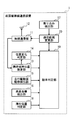
- FIG. 2 is a functional block diagram illustrating an example of a schematic configuration of the short-range wireless communication device 1 related to the communication range change process.
- the short-range wireless communication device 1 includes a wireless communication unit 11, a mobile terminal position estimation unit 13, a position change determination unit 14, a travel drive source operation detection unit 15, an occupant presence / absence detection unit 16, and a boarding detection unit. 17, a stay position determination unit 18, a parking determination unit 19, and a communication range change unit 20.
- the wireless communication unit 11 has a single antenna 12 and performs short-range wireless communication with the mobile terminal 2 having a communication range of several tens of meters at the maximum.
- the antenna 12 is, for example, a transmission / reception antenna.
- short-range wireless communication from the viewpoint of convenience, near-field wireless communication standards such as Bluetooth (registered trademark) and Wi-Fi (registered trademark) that are standardly used in multi-function mobile phones are used. It is preferable to employ distance wireless communication.
- the mobile terminal 2 is used instead of the electronic key, and the UHF band is used to share the wireless communication unit 11 with the wireless communication unit used in the electronic key system. It is good also as a structure which employ
- the wireless communication unit 11 may have one transmission antenna and one reception antenna instead of the single transmission / reception antenna. Good.
- the wireless communication unit 11 is shared with a wireless communication unit used in the electronic key system, a configuration in which a plurality of antennas used in the electronic key system are additionally provided may be employed.
- the mobile terminal position estimation unit 13 sequentially estimates the position of the mobile terminal 2 with respect to the vehicle A.
- the distance of the mobile terminal 2 from the vehicle A is estimated from the received radio wave intensity (that is, RSSI) of the signal received from the mobile terminal 2 by the wireless communication unit 11.
- RSSI radio wave intensity
- both the mobile terminal 2 and the device mounted on the vehicle A have a positioning function for positioning the current position using GNSS (Global Navigation Satellite System)
- GNSS Global Navigation Satellite System
- the positioning position of the portable terminal 2 may be made available by being received by the wireless communication unit 11. What is necessary is just to acquire the positioning position of the vehicle A from the apparatus mounted in the vehicle A.
- the position change determination unit 14 determines whether the position of the mobile terminal 2 with respect to the vehicle A sequentially estimated by the mobile terminal position estimation unit 13 has not changed for a certain time. As an example, when the distance from the position at the start of counting for a certain time to the position at the end of counting for a certain time is less than a threshold that can be said to be an error, the mobile terminal 2 with respect to the vehicle A It may be determined that the position has not changed for a certain time.
- the fixed time may be a time that can be said that the mobile terminal 2 is placed somewhere, and can be set arbitrarily.
- the traveling drive source operation detection unit 15 detects on / off of the traveling drive source of the vehicle A. For example, when the vehicle A uses an engine as a travel drive source, the on / off state of the engine is detected. When the vehicle A uses a motor as a travel drive source, the on / off state of the motor is detected. In the present embodiment, the following description will be given by taking as an example the case of detecting on / off of the engine.
- the on / off of the engine may be detected from the signal of the ignition switch.
- the occupant presence / absence detection unit 16 detects the presence / absence of an occupant in the cabin of the vehicle A.
- the presence / absence of an occupant in the passenger compartment of the vehicle A may be detected from a signal from a seating sensor provided in the seat of the vehicle A.
- the boarding detection unit 17 detects boarding of a passenger in the vehicle A.
- the occupant's boarding in the vehicle A may be detected from the signal of the door courtesy switch and the signal of the seating sensor.
- the occupant to be detected by the occupant presence / absence detection unit 16 or the boarding detection unit 17 may be limited to the occupant carrying the mobile terminal 2.
- the occupant presence / absence detection unit 16 determines whether or not there is an occupant in the vehicle interior of the vehicle A depending on whether or not the position of the mobile terminal 2 is estimated by the mobile terminal position estimation unit 13 within a range corresponding to the vehicle interior. What is necessary is just to detect.
- the boarding detection unit 17 detects the boarding of an occupant in the vehicle A depending on whether or not the mobile terminal position estimation unit 13 has estimated the position of the mobile terminal 2 within a range corresponding to the passenger compartment. do it.
- the portable terminal 2 When sharing the wireless communication unit 11 with the wireless communication unit used in the electronic key system, it is determined whether or not the portable terminal 2 is located in the vehicle interior by using the vehicle interior matching process in the electronic key system, The presence or absence of an occupant in the passenger compartment of the vehicle A and the occupant getting into the vehicle A may be detected.
- the stay position determination unit 18 determines whether or not the vehicle A is located at a predetermined location. Examples of the predetermined location include a home and a destination. Whether or not the vehicle A is located at a predetermined location is determined based on whether the device mounted on the vehicle A has a positioning function for positioning the current position using the GNSS. This positioning position may be determined based on whether or not the position of the predetermined position matches the position registered in advance. In addition, the position information of the Wi-Fi access point at a predetermined location is registered in advance in the short-range wireless communication device 1, and the vehicle A determines whether or not the vehicle A has received a radio wave from the Wi-Fi access point. It is good also as a structure which determines whether it is located in a place.
- the parking determination unit 19 determines whether or not the vehicle A is parked.
- the parking determination unit 19 includes an estimation result in the mobile terminal position estimation unit 13, a position change determination unit 14, a determination result in the stay position determination unit 18, a detection result in the traveling drive source operation detection unit 15, and an occupant presence / absence detection unit 16. Based on the above, it is determined whether or not the vehicle A is parked. Details of the processing in the parking determination unit 19 will be described later.
- the communication range changing unit 20 changes the communication range of the wireless communication unit 11 based on the determination result in the parking determination unit 19 and the detection result in the boarding detection unit 17. As an example, the change of the communication range is performed by changing the transmission output of the antenna 12 to change the communication range of the wireless communication unit 11.
- the communication range changing unit 20 sets a wide communication range by default.
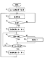
- the flowchart of FIG. 3 may be configured to start when the short-range wireless communication device 1 is turned on and end when the short-range wireless communication device 1 is turned off, for example.
- a switch for switching whether or not the short-range wireless communication device 1 is used by a user operation it starts when a user operation with use is accepted by the switch, and a user operation with no use is accepted by the switch. It is good also as a structure which is complete
- the communication range changing unit 20 sets a wide communication range as the communication range of the wireless communication unit 11, and when there is a portable terminal 2 that can be connected to the wireless communication unit 11, wireless communication with the portable terminal 2 is performed. I do.
- the parking determination unit 19 performs a parking determination for determining whether or not the vehicle A is parked.
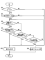
- the outline of parking determination is demonstrated using the flowchart of FIG.
- the communication range changing unit 20 changes the communication range of the wireless communication unit 11 from a wide communication range to a narrow communication range.
- the communication range of the wireless communication unit 11 is narrowly changed without stopping the operation of the wireless communication unit 11. More specifically, the communication range of the wireless communication unit 11 is narrowly changed by suppressing the transmission output of the antenna 12 without losing transmission from the antenna 12.
- the short-range wireless communication device 1 shifts to the intermittent mode in which the radio wave transmission period or the reception period in the wireless communication unit 11 is changed to reduce the power consumption, and the process proceeds to S7. After shifting to the intermittent mode, the intermittent mode is continued until communication is possible in S5, and when communication is possible in S5, the intermittent mode is terminated.
- the process proceeds to S8.
- the boarding detection part 17 has not detected the boarding of the passenger
- the communication range changing unit 20 changes the communication range of the wireless communication unit 11 from a narrow communication range to a wide communication range, and returns to S2 to repeat the processing.
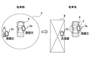
- FIG. C in FIG. 5 represents a communication range of the wireless communication unit 11 of the short-range wireless communication device 1 mounted on the vehicle A.
- FIG. 5 shows a situation before parking of the vehicle A and a situation after parking of the vehicle A.
- the building B in FIG. 5 is assumed to be a home, for example.
- the communication range of the wireless communication unit 11 is a wide communication range. Therefore, the portable terminal 2a in the passenger compartment of the vehicle A can use services such as hands-free calling and audio streaming by wireless communication with the wireless communication unit 11. Further, a service for notifying the presence of the user of the mobile terminal 2b located around the vehicle A while traveling can be used.
- the communication range of the wireless communication unit 11 is changed to a communication range narrower than the communication range before the parking is determined. Therefore, the short-range wireless communication device 1 of the vehicle A parked in the home parking lot communicates with the mobile terminal 2b placed in the building B as a home, even though the user does not want communication connection. The situation is less likely to occur. Therefore, useless communication connection between the short-range wireless communication device 1 and the portable terminal 2b can be suppressed, and useless power consumption of the short-range wireless communication device 1 and the portable terminal 2b can be suppressed.
- wireless communication can be performed within the communication range.
- services such as hands-free calling and audio streaming can be continuously used by wireless communication with the wireless communication unit 11.
- the communication range extends to the vicinity of the vehicle A, services such as data communication and remote operation can be continuously used if the mobile terminal 2 is brought close to the vehicle A even outside the vehicle.
- the communication range is changed widely, so that the user does not perform any operation, It is possible to resume the use of a service that requires a wide communication range when a passenger is on board.
- the parking determination is determined based on various conditions other than the engine off, so that the accuracy of the parking determination can be increased.
- the communication range of the wireless communication unit 11 is changed by changing the transmission output of one antenna 12, so that the cost can be reduced compared to the configuration using a plurality of antennas. it can.
- Embodiment 1 Although the structure which changes the communication range of the radio
- the short-range wireless communication device 1 of Modification 1 is the same as the short-range wireless communication device 1 of Embodiment 1 except that the processing related to the change of the communication range in the communication range change unit 20 is partially different.
- the communication range changing unit 20 sets the communication range “large” as the communication range of the wireless communication unit 11, and when there is a mobile terminal 2 that can be connected to the wireless communication unit 11, the mobile terminal 2 Perform wireless communication.
- the parking determination unit 19 performs parking determination to determine whether or not the vehicle A is parked in the same manner as S2 described above.
- S103 when it determines with parking by the parking determination of S102 (it is YES at S103), it moves to S104.
- S104 when it is determined that the parking is not performed in the parking determination in S102 (NO in S103), the process returns to S102 and is repeated.
- the communication range changing unit 20 changes the communication range of the wireless communication unit 11 to a communication range that is one step narrower than the communication range so far.
- the communication range is “large”, the communication range is changed to “medium”, and when the communication range is “medium”, the communication range is changed to “small”.
- the communication range of the wireless communication unit 11 is narrowly changed without stopping the operation of the wireless communication unit 11 as in S4 described above.
- the communication range of the wireless communication unit 11 is changed to a narrow communication range, so that useless communication connection between the short-range wireless communication device 1 and the portable terminal 2 is achieved. It becomes possible to suppress the wasteful power consumption of the short-range wireless communication device 1 and the portable terminal 2.
- the communication range is divided into a plurality of stages and is changed narrowly in stages, and if necessary, the change is stopped in the middle of the stage. It becomes possible to use the service.
- An example is described below. For example, if there is a terminal in a communication connection position in the communication range “medium” and the service is used in this communication range, stop the communication range from being narrowed to the communication range “small” “Medium” allows you to continue using the service. Therefore, it becomes possible to use the service in the communication range according to the user's needs without making the communication range too narrow.
- Modification 2 Also, unlike the first modification, when the communication range of the wireless communication unit 11 is gradually reduced, the communication range is gradually reduced every time a certain time elapses. Alternatively, the communication range may be narrowed.
- Modification 3 In the modification 1 and the modification 2, the example of the case where the communication range is divided into a plurality of stages and changed in stages is given. However, when the communication range is changed widely, the communication range is divided into a plurality of stages in the same manner. It is good also as a structure changed widely in steps.
- Modification 4 The configuration is not limited to the configuration in which the communication range is changed by changing the transmission output of the antenna 12, but the configuration in which the communication range is changed by switching the antenna to be used from among a plurality of antennas having different communication ranges (hereinafter, modifications). 4). Below, this modification 4 is demonstrated using drawing.
- the short-range wireless communication system 100 of the modification 4 is the same as the short-range wireless communication system 100 of the first embodiment except that the short-range wireless communication device 1a is included instead of the short-range wireless communication device 1. .
- the short-range wireless communication device 1a includes a wireless communication unit 11a, a portable terminal position estimation unit 13, a position change determination unit 14, a travel drive source operation detection unit 15, an occupant presence detection unit 16, and a boarding detection unit. 17, the stay position determination part 18, the parking determination part 19, and the communication range change part 20a are provided.
- the short-range wireless communication device 1a includes the wireless communication unit 11a and the communication range change unit 20a instead of the wireless communication unit 11 and the communication range change unit 20, except that the short-range wireless communication device 1 according to the first embodiment. It is the same.
- the short-range wireless communication device 1a also corresponds to the vehicle-mounted device.
- the wireless communication unit 11a is the same as the wireless communication unit 11 of the first embodiment except that the wireless communication unit 11a includes a plurality of antennas 12a and 12b. It is assumed that the antennas 12a and 12b have different communication ranges. Here, the following description is continued assuming that the communication range of the antenna 12a is wider than the communication range of the antenna 12b.
- the communication range changing unit 20a is the same as the communication range changing unit 20 of the first embodiment except that the method of changing the communication range is different from the communication range changing unit 20 of the first embodiment.
- the communication range changing unit 20a changes the communication range by switching the antenna to be used from among the antennas 12a and 12b. For example, when the communication range is widened, the antenna 12a is used, and when the communication range is narrowed, the antenna 12b is used.
- antenna 12a, 12b the structure which uses two antennas, such as antenna 12a, 12b, was shown here as an example, it does not necessarily restrict to this.
- a configuration may be adopted in which the communication range is changed in a plurality of stages more than two stages using a plurality of antennas greater than two.
- the communication range of the wireless communication unit 11a is changed to a narrow communication range, so that a wasteful communication connection between the short-range wireless communication device 1a and the portable terminal 2 is established. It becomes possible to suppress the wasteful power consumption of the short-range wireless communication device 1a and the portable terminal 2. Moreover, according to the structure of the modification 4, it becomes possible to change the communication range of the radio
- Modification 5 As a method of changing the communication range of the wireless communication unit 11a having the plurality of antennas 12a and 12b, a method of changing the communication range by changing the number of antennas to be used may be employed.
- Modification 6 As a method of changing the communication range of the wireless communication unit 11a having the plurality of antennas 12a and 12b, the communication range of the wireless communication unit 11a is changed by changing the transmission output of the plurality of antennas 12a and 12b. It is good also as composition to do.
- the parking determination flowchart shown in FIG. 4 may be configured to move to S23 if YES in S21.
- the short-range wireless communication devices 1 and 1a may not include the position change determination unit 14, and the determination result as to whether or not the position of the mobile terminal 2 with respect to the vehicle A has not changed for a certain time may not be used for parking determination. Good.
- the parking determination flowchart shown in FIG. 4 may be configured to move to S27 when NO in S23 and S24.
- the parking determination flowchart shown in FIG. 4 may be configured to return to S23 and repeat the process when S26 is NO, or may be configured to shift to S28.
Landscapes
- Engineering & Computer Science (AREA)
- Computer Networks & Wireless Communication (AREA)
- Signal Processing (AREA)
- Telephone Function (AREA)
- Mobile Radio Communication Systems (AREA)
Abstract
車両に搭載されるとともに、通信範囲に位置する携帯端末と通信接続して無線通信を行う無線通信部(11,11a)を備え、無線通信部での無線通信を用いたサービスを行う車載器であって、車両が駐車したか否かを判定する駐車判定部(19)と、駐車判定部で車両が駐車したと判定した場合に、無線通信部の通信範囲を、駐車判定部で車両が駐車したと判定する前よりも狭くする通信範囲変更部(20,20a)と、を備える。
Description
本出願は、2015年3月6日に出願された日本出願番号2015-45149号に基づくもので、ここにその記載内容を援用する。
本開示は、携帯端末との間で無線通信を行う車載器に関するものである。
特許文献1に開示されているように、ユーザが携帯する携帯端末と車両に搭載された車載器との無線通信を用いて、ハンズフリー通話などの種々のサービスをユーザが受けられるようにする技術が知られている。一般的には、携帯端末と無線通信を行う車載器は、携帯端末が通信範囲内にあれば、携帯端末と通信接続してサービスを行い、携帯端末が通信範囲外になれば、通信接続が切断されてサービスを終了する。
携帯端末と車載器との無線通信を用いたサービスは、特許文献1に開示のハンズフリー通話といった車室内に限るサービスだけではない。例えば、車両のイグニッション電源をオフした後も車両のデータを車外で受け取るデータ通信や、車外から車両の機器を操作するリモート操作といったサービスの需要も今後見込まれる。このデータ通信やリモート操作のサービスのように、車外の携帯端末と車載器が無線通信を行う必要がある場合には、車載機の通信範囲を車外にまで広げて設定する必要がある。
しかしながら、車両のイグニッション電源をオフした後も通信接続可能な車載機の通信範囲を車外にまで広げて設定する場合、ユーザが意図しない状況でも携帯端末と車載器とが通信接続してしまう場合がある。例えば、ユーザが通信接続を望んでいないにも関わらず、自宅駐車場に駐車した車両の車載器が、自宅に置かれた携帯端末と通信接続してしまう場合などが考えられる。ユーザが意図しない状況でも車載器と携帯端末とが通信接続してしまう場合、車載機及び携帯端末の電力を無駄に消費してしまうことになる。
本開示は、携帯端末との間での無線通信を用いたサービスを行う車載器に関し、携帯端末との無駄な通信接続を抑えることにより、車載器及び携帯端末の無駄な消費電力を抑制することが可能な車載器を提供することを目的とする。
本開示の一態様によれば、車載器は、車両に搭載されるとともに、通信範囲に位置する携帯端末と通信接続して無線通信を行う無線通信部を備え、無線通信部での無線通信を用いたサービスを行う車載器であって、車両が駐車したか否かを判定する駐車判定部と、駐車判定部で車両が駐車したと判定した場合に、無線通信部の通信範囲を、駐車判定部で車両が駐車したと判定する前よりも狭くする通信範囲変更部とを備える。
これによれば、駐車判定部で車両が駐車したと判定した場合に、通信範囲変更部が、無線通信部の通信範囲を、駐車判定部で車両が駐車したと判定する前よりも狭くするので、車両の駐車時には通信範囲を狭くすることができる。車両の駐車時に通信範囲を狭くすることができると、ユーザが通信接続を望んでいないにも関わらず、自宅駐車場に駐車した車両の車載器が、自宅に置かれた携帯端末と通信接続してしまう状況が生じにくくなる。従って、車載機と携帯端末との無駄な通信接続を抑えることが可能になり、車載器及び携帯端末の無駄な消費電力を抑制することが可能になる。その結果、携帯端末との間での無線通信を用いたサービスを行う車載器において、車載器及び携帯端末の無駄な消費電力を抑制することが可能になる。
本開示についての上記目的およびその他の目的、特徴や利点は、添付の図面を参照しながら下記の詳細な記述により、より明確になる。
近距離無線通信システムの概略的な構成の一例を示す図である。
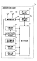
近距離無線通信装置の概略的な構成の一例を示す機能ブロック図である。
実施形態1における近距離無線通信装置での通信範囲変更処理の流れの一例を示すフローチャートである。
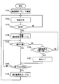
通信範囲変更処理における駐車判定の流れの一例を示すフローチャートである。
実施形態1の構成による作用効果を説明するための図である。
変形例1における近距離無線通信装置での通信範囲変更処理の流れの一例を示すフローチャートである。
近距離無線通信装置の概略的な構成の一例を示す機能ブロック図である。
(実施形態1)
<近距離無線通信システム100の概略構成>
以下、本開示の実施形態について図面を用いて説明する。図1は、本開示が適用された近距離無線通信システム100の概略的な構成の一例を示す図である。図1に示すように、近距離無線通信システム100は、車両Aに搭載された近距離無線通信装置1、携帯端末2a、及び携帯端末2bを含んでいる。
<近距離無線通信システム100の概略構成>
以下、本開示の実施形態について図面を用いて説明する。図1は、本開示が適用された近距離無線通信システム100の概略的な構成の一例を示す図である。図1に示すように、近距離無線通信システム100は、車両Aに搭載された近距離無線通信装置1、携帯端末2a、及び携帯端末2bを含んでいる。
携帯端末2a及び携帯端末2bは、ユーザが携帯して持ち運ぶことができる多機能携帯電話機等の携帯端末である。携帯端末2aは、車両Aの車室内に位置し、携帯端末2bは、建物Bの室内といった車両Aから離れた場所に位置する。一例として、携帯端末2aと携帯端末2bとは、近距離無線通信装置1に対する位置が異なる点を除けば、同様の携帯端末であるものとし、以降では両者を区別しない場合には携帯端末2と呼ぶものとする。
なお、本実施形態では、近距離無線通信システム100に複数の携帯端末を含む構成を例に挙げて説明を行うが、近距離無線通信システム100に1台の携帯端末しか含まない構成としてもよい。
近距離無線通信装置1は、前述したように車両Aに搭載されるものであって、自装置の通信範囲に位置する携帯端末2と通信接続して無線通信を行い、車両Aに搭載された機器を制御して、この無線通信を用いたサービスを行う。
サービスの一例としては、携帯端末2で通話を行う代わりに車両Aに搭載されたスピーカおよびマイクを用いて通話を行うハンズフリー通話、携帯端末2に記憶されている楽曲をカーオーディオで再生させるオーディオストリーミングがある。他にも、車両Aの機器から携帯端末2が情報を取得するデータ通信、携帯端末2から車両Aの機器を操作するリモート操作もある。また、車両Aの周辺に位置する携帯端末2のユーザの存在を走行中などに報知するサービスなども考えられる。データ通信で携帯端末2が取得する情報の一例としては、車両Aの平均燃費や走行距離やタイヤ空気圧などが挙げられる。リモート操作の一例としては、車外からカーエアコンを起動させる操作などが挙げられる。
また、近距離無線通信装置1は、条件に応じて通信範囲を変更する通信範囲変更処理を行う。通信範囲変更処理の詳細については後述する。近距離無線通信装置1が車載器に相当する。
<近距離無線通信装置1の概略構成>
ここで、図2を用いて、近距離無線通信装置1の前述した通信範囲変更処理に関連する構成について説明を行う。図2は、通信範囲変更処理に関連する近距離無線通信装置1の概略的な構成の一例を示す機能ブロック図である。図2に示すように、近距離無線通信装置1は、無線通信部11、携帯端末位置推定部13、位置変化判定部14、走行駆動源動作検出部15、乗員有無検出部16、乗り込み検出部17、滞在位置判定部18、駐車判定部19、及び通信範囲変更部20を備えている。
ここで、図2を用いて、近距離無線通信装置1の前述した通信範囲変更処理に関連する構成について説明を行う。図2は、通信範囲変更処理に関連する近距離無線通信装置1の概略的な構成の一例を示す機能ブロック図である。図2に示すように、近距離無線通信装置1は、無線通信部11、携帯端末位置推定部13、位置変化判定部14、走行駆動源動作検出部15、乗員有無検出部16、乗り込み検出部17、滞在位置判定部18、駐車判定部19、及び通信範囲変更部20を備えている。
無線通信部11は、1本のアンテナ12を有しており、携帯端末2との間で、通信範囲が最大でも数十メートル程度の近距離無線通信を行う。このアンテナ12は例えば送受信アンテナとする。近距離無線通信としては、利便性の点から、多機能型携帯電話機で標準的に用いられているBluetooth(登録商標)やWi-Fi(登録商標)等の近距離無線通信規格に従った近距離無線通信を採用することが好ましい。他にも、スマートエントリーシステムといった電子キーシステムにおいて、電子キーの代わりに携帯端末2を用いるとともに、無線通信部11を電子キーシステムで用いる無線通信部と共有にするために、UHF帯を用いた近距離無線通信を採用する構成としてもよい。
なお、送信に用いるアンテナが1本であれば、1本の送受信アンテナを無線通信部11が有する代わりに、1本の送信アンテナと1本の受信アンテナとを無線通信部11が有する構成としてもよい。また、無線通信部11を、電子キーシステムで用いる無線通信部と共有する場合には、電子キーシステムで用いるアンテナを他に複数本有する構成としてもよい。
携帯端末位置推定部13は、車両Aに対する携帯端末2の位置を逐次推定する。一例としては、無線通信部11で携帯端末2から受信した信号の受信電波強度(つまり、RSSI)から、車両Aから携帯端末2がどの程度離れた距離の位置にあるかを推定する。他にも、携帯端末2と車両Aに搭載されている機器とのいずれもが、GNSS(Global Navigation Satellite System)を用いて現在位置を測位する測位機能を有している場合には、GNSSを用いて測位した携帯端末2及び車両Aの測位位置から、車両Aに対する携帯端末2の位置を推定すればよい。携帯端末2の測位位置は、無線通信部11で受信することで利用可能とすればよい。車両Aの測位位置は、車両Aに搭載されている機器から取得すればよい。
位置変化判定部14は、携帯端末位置推定部13で逐次推定する車両Aに対する携帯端末2の位置が、一定時間変化していないか否かを判定する。一例としては、一定時間のカウントを開始したときの位置から一定時間のカウントを終了したときの位置までの距離が、誤差と言える程度の閾値未満であった場合に、車両Aに対する携帯端末2の位置が一定時間変化していないと判定すればよい。一定時間は、携帯端末2がどこかに置かれたと言える程度の時間であればよく、任意に設定可能である。
走行駆動源動作検出部15は、車両Aの走行駆動源のオンオフを検出する。例えば、車両Aがエンジンを走行駆動源としている場合には、このエンジンのオンオフを検出し、車両Aがモータを走行駆動源としている場合には、このモータのオンオフを検出する。本実施形態では、エンジンのオンオフを検出する場合を例に挙げて以降の説明を行う。エンジンのオンオフは、イグニッションスイッチの信号から検出すればよい。
乗員有無検出部16は、車両Aの車室内の乗員の有無を検出する。一例としては、車両Aの座席に設けられた着座センサの信号から、車両Aの車室内の乗員の有無を検出すればよい。乗り込み検出部17は、車両Aへの乗員の乗り込みを検出する。一例として、ドアカーテシスイッチの信号と着座センサの信号から、車両Aへの乗員の乗り込みを検出すればよい。他にも、アウタードアハンドルに設けられたタッチスイッチの信号から、車両Aの乗員の乗り込みを検出するなどしてもよい。
なお、乗員有無検出部16や乗り込み検出部17で検出の対象とする乗員は、携帯端末2を携帯する乗員に限る構成としてもよい。この場合、乗員有無検出部16は、車室内に相当する範囲内に、携帯端末位置推定部13で携帯端末2の位置が推定されるか否かによって、車両Aの車室内の乗員の有無を検出すればよい。また、乗り込み検出部17は、車室内に相当する範囲内に、携帯端末位置推定部13で携帯端末2の位置が推定されるようになったか否かによって、車両Aへの乗員の乗り込みを検出すればよい。
無線通信部11を電子キーシステムで用いる無線通信部と共有する場合には、電子キーシステムにおける車室内照合の処理を利用して、携帯端末2が車室内に位置するか否かを判定し、車両Aの車室内の乗員の有無や車両Aへの乗員の乗り込みを検出してもよい。
滞在位置判定部18は、車両Aが所定場所に位置しているか否かを判定する。所定場所としては、例えば自宅や目的地などがある。車両Aが所定場所に位置しているか否かは、車両Aに搭載されている機器がGNSSを用いて現在位置を測位する測位機能を有している場合には、この機器で測位した車両Aの測位位置と、予め登録しておいた所定場所の位置とが一致するか否かによって判定すればよい。他にも、所定場所のWi-Fiアクセスポイントの位置情報を近距離無線通信装置1に予め登録しておき、このWi-Fiアクセスポイントからの電波を受信したか否かによって、車両Aが所定場所に位置しているか否かを判定する構成としてもよい。
駐車判定部19は、車両Aが駐車したか否かを判定する。駐車判定部19は、携帯端末位置推定部13での推定結果、位置変化判定部14、滞在位置判定部18での判定結果、走行駆動源動作検出部15、乗員有無検出部16での検出結果をもとに、車両Aが駐車したか否かを判定する。駐車判定部19での処理の詳細については後述する。
通信範囲変更部20は、駐車判定部19での判定結果や乗り込み検出部17での検出結果をもとに、無線通信部11の通信範囲を変更する。通信範囲の変更は、一例として、無線通信部11の通信範囲の変更は、アンテナ12の送信出力を変更することで行う。本実施形態では、通信範囲として、車両Aの近傍に限られた狭い通信範囲と、車両Aから例えば数メートル離れた領域まで広がる広い通信範囲との2種類があるものとする。また、通信範囲変更部20によって、デフォルトでは広い通信範囲が設定されるものとする。
<通信範囲変更処理>
続いて、図3のフローチャートを用いて、近距離無線通信装置1での通信範囲変更処理の流れの一例について説明を行う。図3のフローチャートは、例えば、近距離無線通信装置1の電源がオンになったときに開始し、近距離無線通信装置1の電源がオフになったときに終了する構成とすればよい。なお、近距離無線通信装置1の使用の有無をユーザ操作によって切り替えるスイッチがある場合には、使用ありとするユーザ操作をスイッチで受け付けた場合に開始し、使用なしとするユーザ操作をスイッチで受け付けた場合に終了する構成としてもよい。
続いて、図3のフローチャートを用いて、近距離無線通信装置1での通信範囲変更処理の流れの一例について説明を行う。図3のフローチャートは、例えば、近距離無線通信装置1の電源がオンになったときに開始し、近距離無線通信装置1の電源がオフになったときに終了する構成とすればよい。なお、近距離無線通信装置1の使用の有無をユーザ操作によって切り替えるスイッチがある場合には、使用ありとするユーザ操作をスイッチで受け付けた場合に開始し、使用なしとするユーザ操作をスイッチで受け付けた場合に終了する構成としてもよい。
まず、S1では、通信範囲変更部20が無線通信部11の通信範囲として広い通信範囲を設定し、無線通信部11と通信接続できる携帯端末2が存在する場合にはその携帯端末2と無線通信を行う。
S2では、駐車判定部19が、車両Aが駐車したか否かを判定する駐車判定を行う。ここで、図4のフローチャートを用いて、駐車判定の概略について説明を行う。
まず、S21では、走行駆動源動作検出部15で車両Aのエンジンがオンからオフになったことを検出した場合(S21でYES)には、S22に移る。一方、車両Aのエンジンがオンからオフになったことを検出していない場合(S21でNO)には、S28に移る。近距離無線通信装置1は、イグニッション電源がオフになった場合でも、例えばバックアップ電源から電力の供給を受けて作動するものとする。
S22では、滞在位置判定部18で車両Aが所定場所に位置していると判定した場合(S22でYES)には、S23に移る。一方、車両Aが所定場所に位置していないと判定した場合(S22でNO)には、S28に移る。
S23では、乗員有無検出部16で車両Aの車室内に乗員がないことを検出した場合(S23でYES)には、S24に移る。一方、車両Aの車室内に乗員があることを検出した場合(S23でNO)には、S26に移る。
S24では、携帯端末位置推定部13で推定した車両Aに対する携帯端末2の位置(つまり、端末位置)が、車両Aから一定距離以上であった場合(S24でYES)には、S25に移る。一方、車両Aから一定距離未満であった場合(S24でNO)には、S26に移る。ここで言うところの一定距離とは、乗員が車両Aから降車したと言える程度の距離以上の距離であればよく、任意に設定可能である。S25では、駐車判定部19が、車両Aが駐車したと判定し、S3に移る。
S26では、位置変化判定部14で車両Aに対する携帯端末2の位置(つまり、端末位置)が一定時間変化していないと判定した場合(S26でYES)には、S25に移る。一方、車両Aに対する携帯端末2の位置が一定時間の間に変化したと判定した場合(S26でNO)には、S27に移る。
S27では、走行駆動源動作検出部15で車両Aのエンジンのオフを検出してから一定時間経過した場合(S27でYES)には、S25に移る。一方、車両Aのエンジンのオフを検出してから一定時間経過していない場合(S27でNO)には、S23に戻って処理を繰り返す。ここで言うところの一定時間とは、位置変化判定部14で用いる一定時間よりも長ければよく、任意に設定可能である。S28では、駐車判定部19が、車両Aが駐車していないと判定し、S3に移る。
図3に戻って、S3では、S2の駐車判定で駐車と判定した場合(S3でYES)には、S4に移る。一方、S2の駐車判定で駐車でないと判定した場合(S3でNO)には、S2に戻って処理を繰り返す。
S4では、通信範囲変更部20が、無線通信部11の通信範囲を、広い通信範囲から狭い通信範囲に変更する。S4では、無線通信部11の動作を停止させることなく、無線通信部11の通信範囲を狭く変更する。より詳しくは、アンテナ12からの送信をなくすことなく、アンテナ12の送信出力を小さく抑えることで、無線通信部11の通信範囲を狭く変更する。
S5では、携帯端末2が無線通信部11の通信範囲内にあり、無線通信部11と携帯端末2とが通信接続されて通信可能である場合(S5でYES)には、S7に移る。一方、携帯端末2が無線通信部11の通信範囲内になく、無線通信部11と携帯端末2とが通信接続されず通信可能でない場合(S5でNO)には、S6に移る。
S6では、近距離無線通信装置1が、無線通信部11における電波の送信周期若しくは受信周期を長く変更して電力消費を抑える間欠モードに移行して、S7に移る。一旦間欠モードに移行した後は、S5で通信可能となるまで間欠モードを継続し、S5で通信可能となった場合に間欠モードを終了する。
S7では、乗り込み検出部17が車両Aへの乗員の乗り込みを検出した場合(S7でYES)には、S8に移る。一方、乗り込み検出部17が車両Aへの乗員の乗り込みを検出していない場合(S7でNO)には、S5に戻って処理を繰り返す。S8では、通信範囲変更部20が、無線通信部11の通信範囲を、狭い通信範囲から広い通信範囲に変更し、S2に戻って処理を繰り返す。
<実施形態1のまとめ>
ここで、実施形態1の構成による作用効果について、具体的に図5を用いて説明を行う。図5のCが車両Aに搭載された近距離無線通信装置1の無線通信部11の通信範囲を表している。図5では、車両Aの駐車前の状況と車両Aの駐車後の状況とを示している。図5の建物Bは、例えば自宅とする。
ここで、実施形態1の構成による作用効果について、具体的に図5を用いて説明を行う。図5のCが車両Aに搭載された近距離無線通信装置1の無線通信部11の通信範囲を表している。図5では、車両Aの駐車前の状況と車両Aの駐車後の状況とを示している。図5の建物Bは、例えば自宅とする。
図5に示すように、車両Aの駐車前には、無線通信部11の通信範囲は広い通信範囲となっている。よって、車両Aの車室内の携帯端末2aでは、無線通信部11との無線通信によって、ハンズフリー通話やオーディオストリーミングといったサービスを利用できる。また、車両Aの周辺に位置する携帯端末2bのユーザの存在を走行中などに報知するサービスも利用できる。
これに対して、車両Aの駐車の判定後(つまり、駐車後)は、無線通信部11の通信範囲は駐車と判定される前の通信範囲よりも狭い通信範囲に変更される。よって、ユーザが通信接続を望んでいないにも関わらず、自宅駐車場に駐車した車両Aの近距離無線通信装置1が、自宅としての建物Bに置かれた携帯端末2bと通信接続してしまう状況が生じにくくなる。従って、近距離無線通信装置1と携帯端末2bとの無駄な通信接続を抑えることが可能になり、近距離無線通信装置1及び携帯端末2bの無駄な消費電力を抑制することが可能になる。
また、実施形態1の構成によれば、無線通信部11の通信範囲を狭い通信範囲に変更した場合であっても、通信範囲内では無線通信を行うことができるので、車両Aの車室内の携帯端末2aとの間では、無線通信部11との無線通信によって、ハンズフリー通話やオーディオストリーミングといったサービスは継続して利用できる。また、車両Aの近傍まで通信範囲が広がっているので、車外であっても車両Aに携帯端末2を近接させれば、データ通信やリモート操作といったサービスも継続して利用できる。
さらに、実施形態1の構成によれば、車両Aの駐車を判定した後、車両Aへの乗員の乗り込みを検出した場合に、通信範囲を広く変更するので、ユーザが何らかの操作を行うことなく、乗員の乗車時に、広い通信範囲を必要とするサービスの利用を再開させることが可能になる。
他にも、実施形態1の構成によれば、駐車の判定を、エンジンのオフだけでない種々の条件によって判定するので、駐車の判定の精度を高くすることができる。また、実施形態1の構成によれば、1本のアンテナ12の送信出力を変更することで無線通信部11の通信範囲を変更するので、複数のアンテナを用いる構成に比べてコストを下げることができる。
(変形例1)
実施形態1では、無線通信部11の通信範囲を広い通信範囲と狭い通信範囲との2段階で変更する構成を示したが、必ずしもこれに限らない。例えば、無線通信部11の通信範囲を、2段階よりも多い複数段階に分けて段階的に変化させる構成(以下、変形例1)としてもよい。
実施形態1では、無線通信部11の通信範囲を広い通信範囲と狭い通信範囲との2段階で変更する構成を示したが、必ずしもこれに限らない。例えば、無線通信部11の通信範囲を、2段階よりも多い複数段階に分けて段階的に変化させる構成(以下、変形例1)としてもよい。
以下では、この変形例1について図面を用いて説明を行う。なお、説明の便宜上、この変形例1以降の説明において、それまでの説明に用いた図に示した部材と同一の機能を有する部材については、同一の符号を付し、その説明を省略する。変形例1の近距離無線通信装置1は、通信範囲変更部20での通信範囲の変更に関する処理が一部異なる点を除けば、実施形態1の近距離無線通信装置1と同様である。
ここで、図6のフローチャートを用いて、変形例1における近距離無線通信装置1での通信範囲変更処理の流れの一例について説明を行う。図6のフローチャートの開始と終了のタイミングは、図3のフローチャートと同様とすればよい。また、ここでは、一例として通信範囲を「大」、「中」、「小」の3段階で変化させる場合を例に挙げて説明を行う。
まず、S101では、通信範囲変更部20が無線通信部11の通信範囲として通信範囲「大」を設定し、無線通信部11と通信接続できる携帯端末2が存在する場合にはその携帯端末2と無線通信を行う。
S102では、前述のS2と同様にして、駐車判定部19が、車両Aが駐車したか否かを判定する駐車判定を行う。S103では、S102の駐車判定で駐車と判定した場合(S103でYES)には、S104に移る。一方、S102の駐車判定で駐車でないと判定した場合(S103でNO)には、S102に戻って処理を繰り返す。
S104では、通信範囲変更部20が、無線通信部11の通信範囲を、それまでの通信範囲よりも一段階狭い通信範囲に変更する。通信範囲「大」であった場合には、通信範囲「中」に変更し、通信範囲「中」であった場合には、通信範囲「小」に変更する。S104でも、前述のS4と同様に、無線通信部11の動作を停止させることなく、無線通信部11の通信範囲を狭く変更する。
S105では、前述のS5と同様にして、無線通信部11と携帯端末2とが通信接続されて通信可能である場合(S105でYES)には、S108に移る。一方、無線通信部11と携帯端末2とが通信接続されず通信可能でない場合(S105でNO)には、S106に移る。
S106では、無線通信部11の通信範囲が通信範囲「小」に達した、つまり、下限に達した場合(S106でYES)には、S107に移る。一方、下限に達していない場合(S106でNO)には、S104に戻って処理を繰り返す。S107では、前述のS6と同様にして、近距離無線通信装置1が間欠モードに移行して、S108に移る。
これによれば、例えば通信範囲「中」に変更されている際に、無線通信部11と携帯端末2とが通信接続されて通信可能である場合には、通信範囲「中」の段階で通信範囲を狭める処理が一旦停止され、通信範囲「中」が保たれることになる。
S108では、乗り込み検出部17が車両Aへの乗員の乗り込みを検出した場合(S108でYES)には、S109に移る。一方、乗り込み検出部17が車両Aへの乗員の乗り込みを検出していない場合(S108でNO)には、S105に戻って処理を繰り返す。S109では、前述のS8と同様にして、通信範囲変更部20が、無線通信部11の通信範囲を例えば通信範囲「大」といった広い通信範囲に変更し、S102に戻って処理を繰り返す。
変形例1の構成によっても、車両Aの駐車の判定後は、無線通信部11の通信範囲を狭い通信範囲に変更するので、近距離無線通信装置1と携帯端末2との無駄な通信接続を抑えることが可能になり、近距離無線通信装置1及び携帯端末2の無駄な消費電力を抑制することが可能になる。
また、変形例1の構成によれば、通信範囲を複数段階に分けて段階的に狭く変更するとともに、必要に応じて、変更を段階の途中で止めるので、ユーザの必要に応じた通信範囲でサービスを利用することが可能になる。一例を以下に述べる。例えば、通信範囲「中」で通信接続される位置に端末があり、この通信範囲でサービスを利用している場合には、通信範囲「小」まで通信範囲を狭くするのを止めて、通信範囲「中」でサービスの利用を続けられるようにすることができる。よって、通信範囲を狭くしすぎることなく、ユーザの必要に応じた通信範囲でサービスを利用することが可能になる。
(変形例2)
また、変形例1とは異なり、段階的に無線通信部11の通信範囲を狭めていく場合に、一定の時間が経過するごとに段階的に通信範囲を狭めていくなど、他の態様で段階的に通信範囲を狭めていく構成としてもよい。
また、変形例1とは異なり、段階的に無線通信部11の通信範囲を狭めていく場合に、一定の時間が経過するごとに段階的に通信範囲を狭めていくなど、他の態様で段階的に通信範囲を狭めていく構成としてもよい。
(変形例3)
なお、変形例1及び変形例2では、通信範囲を複数段階に分けて段階的に狭く変更する場合の例を挙げたが、通信範囲を広く変更する場合にも、同様に複数段階に分けて段階的に広く変更する構成としてもよい。
なお、変形例1及び変形例2では、通信範囲を複数段階に分けて段階的に狭く変更する場合の例を挙げたが、通信範囲を広く変更する場合にも、同様に複数段階に分けて段階的に広く変更する構成としてもよい。
(変形例4)
なお、アンテナ12の送信出力を変更することで通信範囲を変更する構成に限らず、それぞれ通信範囲の異なる複数のアンテナのうちから用いるアンテナを切り替えることで通信範囲を変更する構成(以下、変形例4)としてもよい。以下では、この変形例4について図面を用いて説明を行う。変形例4の近距離無線通信システム100は、近距離無線通信装置1の代わりに近距離無線通信装置1aを含んでいる点を除けば、実施形態1の近距離無線通信システム100と同様である。
なお、アンテナ12の送信出力を変更することで通信範囲を変更する構成に限らず、それぞれ通信範囲の異なる複数のアンテナのうちから用いるアンテナを切り替えることで通信範囲を変更する構成(以下、変形例4)としてもよい。以下では、この変形例4について図面を用いて説明を行う。変形例4の近距離無線通信システム100は、近距離無線通信装置1の代わりに近距離無線通信装置1aを含んでいる点を除けば、実施形態1の近距離無線通信システム100と同様である。
近距離無線通信装置1aは、図7に示すように、無線通信部11a、携帯端末位置推定部13、位置変化判定部14、走行駆動源動作検出部15、乗員有無検出部16、乗り込み検出部17、滞在位置判定部18、駐車判定部19、及び通信範囲変更部20aを備えている。近距離無線通信装置1aは、無線通信部11、通信範囲変更部20の代わりに無線通信部11a、通信範囲変更部20aを備えている点を除けば、実施形態1の近距離無線通信装置1と同様である。近距離無線通信装置1aも車載器に相当する。
無線通信部11aは、複数本のアンテナ12a,12bを有している点を除けば、実施形態1の無線通信部11と同様である。アンテナ12a,12bは、それぞれ通信範囲が異なっているものとする。ここでは、アンテナ12aの通信範囲の方が、アンテナ12bの通信範囲よりも広いものとして以降の説明を続ける。
通信範囲変更部20aは、通信範囲を変更する方法が実施形態1の通信範囲変更部20と異なっている点を除けば、実施形態1の通信範囲変更部20と同様である。通信範囲変更部20aでは、アンテナ12a,12bのうちから用いるアンテナを切り替えることで通信範囲を変更する。例えば、通信範囲を広くする場合には、アンテナ12aを用いるようにし、通信範囲を狭くする場合には、アンテナ12bを用いるようにする。
なお、ここでは一例としてアンテナ12a,12bといった2本のアンテナを用いる構成を示したが、必ずしもこれに限らない。例えば、2本よりも多い複数のアンテナを用いて、2段階よりも多い複数段階に分けて通信範囲を変更する構成としてもよい。
変形例4の構成によっても、車両Aの駐車の判定後は、無線通信部11aの通信範囲を狭い通信範囲に変更するので、近距離無線通信装置1aと携帯端末2との無駄な通信接続を抑えることが可能になり、近距離無線通信装置1a及び携帯端末2の無駄な消費電力を抑制することが可能になる。また、変形例4の構成によれば、アンテナの送信出力を変更しなくても無線通信部11aの通信範囲を変更することが可能になる。
(変形例5)
なお、複数のアンテナ12a,12bを有する無線通信部11aの通信範囲を変更する方法としては、使用するアンテナの数を変更することで通信範囲を変更する方法を採用してもよい。
なお、複数のアンテナ12a,12bを有する無線通信部11aの通信範囲を変更する方法としては、使用するアンテナの数を変更することで通信範囲を変更する方法を採用してもよい。
(変形例6)
他にも、複数のアンテナ12a,12bを有する無線通信部11aの通信範囲を変更する方法としては、複数のアンテナ12a,12bの送信出力を変更することで、無線通信部11aの通信範囲を変更する構成としてもよい。
他にも、複数のアンテナ12a,12bを有する無線通信部11aの通信範囲を変更する方法としては、複数のアンテナ12a,12bの送信出力を変更することで、無線通信部11aの通信範囲を変更する構成としてもよい。
(変形例7)
また、近距離無線通信装置1,1aに滞在位置判定部18を備えず、車両Aが所定場所に位置しているか否かの判定結果を駐車判定に用いない構成としてもよい。この場合、図4で示した駐車判定のフローチャートは、S21でYESの場合にS23に移る構成とすればよい。
また、近距離無線通信装置1,1aに滞在位置判定部18を備えず、車両Aが所定場所に位置しているか否かの判定結果を駐車判定に用いない構成としてもよい。この場合、図4で示した駐車判定のフローチャートは、S21でYESの場合にS23に移る構成とすればよい。
(変形例8)
また、近距離無線通信装置1,1aに位置変化判定部14を備えず、車両Aに対する携帯端末2の位置が一定時間変化していないか否かの判定結果を駐車判定に用いない構成としてもよい。この場合、図4で示した駐車判定のフローチャートは、S23,S24でNOの場合にS27に移る構成とすればよい。
また、近距離無線通信装置1,1aに位置変化判定部14を備えず、車両Aに対する携帯端末2の位置が一定時間変化していないか否かの判定結果を駐車判定に用いない構成としてもよい。この場合、図4で示した駐車判定のフローチャートは、S23,S24でNOの場合にS27に移る構成とすればよい。
(変形例9)
また、走行駆動源動作検出部15で車両Aのエンジンのオフを検出してから一定時間経過したか否かの判定結果を駐車判定に用いない構成としてもよい。この場合、図4で示した駐車判定のフローチャートは、S26でNOの場合にS23に戻って処理を繰り返す構成としてもよいし、S28に移る構成としてもよい。
また、走行駆動源動作検出部15で車両Aのエンジンのオフを検出してから一定時間経過したか否かの判定結果を駐車判定に用いない構成としてもよい。この場合、図4で示した駐車判定のフローチャートは、S26でNOの場合にS23に戻って処理を繰り返す構成としてもよいし、S28に移る構成としてもよい。
(変形例10)
駐車判定部19で車両Aの駐車と判定した場合であって、且つ、無線通信部11,11aと携帯端末2とが通信接続されず通信可能でない場合に、間欠モードに移行する構成を示したが、必ずしもこれに限らない。例えば、間欠モードに移行する代わりに、無線通信部11,11aからの電波の送信を停止する構成としてもよい。
駐車判定部19で車両Aの駐車と判定した場合であって、且つ、無線通信部11,11aと携帯端末2とが通信接続されず通信可能でない場合に、間欠モードに移行する構成を示したが、必ずしもこれに限らない。例えば、間欠モードに移行する代わりに、無線通信部11,11aからの電波の送信を停止する構成としてもよい。
本開示は、実施形態に準拠して記述されたが、本開示は当該実施形態や構造に限定されるものではないと理解される。本開示は、様々な変形例や均等範囲内の変形をも包含する。加えて、様々な組み合わせや形態、さらには、それらに一要素のみ、それ以上、あるいはそれ以下、を含む他の組み合わせや形態をも、本開示の範疇や思想範囲に入るものである。
Claims (11)
- 車両に搭載されるとともに、
通信範囲に位置する携帯端末と通信接続して無線通信を行う無線通信部(11,11a)を備え、
前記無線通信部での前記無線通信を用いたサービスを行う車載器であって、
前記車両が駐車したか否かを判定する駐車判定部(19)と、
前記駐車判定部で前記車両が駐車したと判定した場合に、前記無線通信部の通信範囲を、前記駐車判定部で前記車両が駐車したと判定する前よりも狭くする通信範囲変更部(20,20a)と、を備える車載器。 - 請求項1において、
前記通信範囲変更部は、前記無線通信部の通信範囲を、2段階よりも多い複数段階に分けて段階的に変化させる車載器。 - 請求項1又は2において、
前記車両の走行駆動源のオンオフを検出する走行駆動源動作検出部(15)と、
前記車両の車室内の乗員の有無を検出する乗員有無検出部(16)と、
前記車両に対する携帯端末の位置を推定する携帯端末位置推定部(13)と、を備え、
前記駐車判定部は、前記走行駆動源動作検出部で前記走行駆動源のオフを検出するとともに、前記乗員有無検出部で前記乗員がないことを検出し、且つ、前記携帯端末位置推定部で逐次推定する前記車両に対する前記携帯端末の位置が前記車両から一定距離以上である場合に、前記車両が駐車したと判定する車載器。 - 請求項1~3のいずれか1項において、
前記車両に対する携帯端末の位置を推定する携帯端末位置推定部(13)を備えるものであって、
前記携帯端末位置推定部で推定する前記携帯端末の位置が一定時間変化していないか否かを判定する位置変化判定部(14)をさらに備え、
前記駐車判定部は、前記位置変化判定部で前記携帯端末の位置が一定時間変化していないと判定した場合に、前記車両が駐車したと判定する車載器。 - 請求項1~4のいずれか1項において、
前記車両の走行駆動源のオンオフを検出する走行駆動源動作検出部(15)を備えるものであって、
前記駐車判定部は、前記走行駆動源動作検出部で前記走行駆動源のオフを検出してから一定時間経過した場合に、前記車両が駐車したと判定する車載器。 - 請求項1~5のいずれか1項において、
前記車両が所定場所に位置しているか否かを判定する滞在位置判定部(18)を備え、
前記駐車判定部は、前記滞在位置判定部での判定結果を用いて、前記車両が前記所定場所に駐車したか否かを判定する車載器。 - 請求項1~6のいずれか1項において、
前記車両への乗員の乗り込みを検出する乗り込み検出部(17)を備え、
前記通信範囲変更部は、前記駐車判定部で前記車両が駐車したと判定して前記無線通信部の通信範囲を狭くした後、前記乗り込み検出部で前記車両への乗員の乗り込みを検出した場合には、前記無線通信部の通信範囲を、前記乗り込み検出部で前記車両への乗員の乗り込みを検出する前よりも広くする車載器。 - 請求項1~7のいずれか1項において、
前記通信範囲変更部は、前記無線通信部の送信出力を変更することで、前記無線通信部の通信範囲を変更する車載器。 - 請求項8において、
前記無線通信部(11)は、送信に用いるアンテナとして、1本のアンテナ(12)を有しているものであって、
前記通信範囲変更部は、前記1本のアンテナの送信出力を変更することで、前記無線通信部の通信範囲を変更する車載器。 - 請求項1~7のいずれか1項において、
前記無線通信部(11a)は、送信に用いるアンテナとして、それぞれ通信範囲の大きさが異なる複数本のアンテナ(12a,12b)を有しているものであって、
前記通信範囲変更部は、前記複数本のアンテナのうちから、用いるアンテナを切り替えることで、前記無線通信部の通信範囲を変更する車載器。 - 請求項1~10のいずれか1項において、
前記無線通信部での前記無線通信を用いて行うサービスは、前記携帯端末から前記車両の機器を操作するサービス、及び前記車両の機器から前記携帯端末が情報を取得するサービスの少なくともいずれかである車載器。
Priority Applications (3)
| Application Number | Priority Date | Filing Date | Title |
|---|---|---|---|
| CN201680012750.8A CN107409365B (zh) | 2015-03-06 | 2016-02-18 | 车载器 |
| DE112016001074.5T DE112016001074B4 (de) | 2015-03-06 | 2016-02-18 | An einem fahrzeug vorzusehende vorrichtung |
| US15/550,919 US10039063B2 (en) | 2015-03-06 | 2016-02-18 | Parking and location determination on-vehicle device |
Applications Claiming Priority (2)
| Application Number | Priority Date | Filing Date | Title |
|---|---|---|---|
| JP2015045149A JP6447256B2 (ja) | 2015-03-06 | 2015-03-06 | 車載器 |
| JP2015-045149 | 2015-03-06 |
Publications (1)
| Publication Number | Publication Date |
|---|---|
| WO2016143269A1 true WO2016143269A1 (ja) | 2016-09-15 |
Family
ID=56876241
Family Applications (1)
| Application Number | Title | Priority Date | Filing Date |
|---|---|---|---|
| PCT/JP2016/000844 Ceased WO2016143269A1 (ja) | 2015-03-06 | 2016-02-18 | 車載器 |
Country Status (5)
| Country | Link |
|---|---|
| US (1) | US10039063B2 (ja) |
| JP (1) | JP6447256B2 (ja) |
| CN (1) | CN107409365B (ja) |
| DE (1) | DE112016001074B4 (ja) |
| WO (1) | WO2016143269A1 (ja) |
Cited By (1)
| Publication number | Priority date | Publication date | Assignee | Title |
|---|---|---|---|---|
| US10800359B2 (en) | 2015-03-11 | 2020-10-13 | Denso Corporation | Short-range wireless communication system and short-range wireless communication device |
Families Citing this family (6)
| Publication number | Priority date | Publication date | Assignee | Title |
|---|---|---|---|---|
| US20180233045A1 (en) * | 2017-02-10 | 2018-08-16 | Vikram Kumar | End-trip detection system |
| JP6904781B2 (ja) * | 2017-05-12 | 2021-07-21 | 矢崎総業株式会社 | 車両用無線通信システム |
| JP6940346B2 (ja) * | 2017-09-13 | 2021-09-29 | 矢崎エナジーシステム株式会社 | 車載器 |
| KR102885739B1 (ko) * | 2020-05-04 | 2025-11-14 | 엘지이노텍 주식회사 | 블루투스 디바이스 |
| US12589713B2 (en) * | 2023-05-25 | 2026-03-31 | Gm Cruise Holdings Llc | Fleet-connected vehicle identification |
| US12464447B2 (en) | 2023-07-24 | 2025-11-04 | GM Global Technology Operations LLC | Selection of offload-opportunity wireless networks that respect personal data |
Citations (6)
| Publication number | Priority date | Publication date | Assignee | Title |
|---|---|---|---|---|
| JP2004343467A (ja) * | 2003-05-16 | 2004-12-02 | Denso Corp | 自動車相互間無線通信装置 |
| JP2005268933A (ja) * | 2004-03-16 | 2005-09-29 | Denso Corp | 無線通信システム |
| JP2010130137A (ja) * | 2008-11-26 | 2010-06-10 | Omron Corp | 情報処理システム、情報処理装置および方法、並びにプログラム |
| JP2012080192A (ja) * | 2010-09-30 | 2012-04-19 | Nec Corp | 無線通信機及び無線通信システム |
| JP2013128244A (ja) * | 2011-12-19 | 2013-06-27 | Toyota Motor Corp | 車載装置 |
| JP2013240132A (ja) * | 2012-05-11 | 2013-11-28 | Toyota Motor Corp | 車両、受電装置、送電装置および非接触給電システム |
Family Cites Families (16)
| Publication number | Priority date | Publication date | Assignee | Title |
|---|---|---|---|---|
| US20070109093A1 (en) | 2005-11-11 | 2007-05-17 | Fujitsu Ten Limited | Vehicle control system and vehicle control apparatus |
| US7915998B2 (en) | 2005-11-11 | 2011-03-29 | Fujitsu Ten Limited | Vehicle control system and vehicle control apparatus |
| JP2007146501A (ja) | 2005-11-28 | 2007-06-14 | Fujitsu Ten Ltd | 車両制御装置 |
| JP2009135706A (ja) * | 2007-11-29 | 2009-06-18 | Toyota Industries Corp | 無線通信装置、無線通信方法、無線通信システム |
| JP5451168B2 (ja) * | 2009-04-28 | 2014-03-26 | アルプス電気株式会社 | 車両のキーレスエントリー装置 |
| JP2012169792A (ja) | 2011-02-11 | 2012-09-06 | Alpine Electronics Inc | 車載システム |
| JP2013032105A (ja) | 2011-08-02 | 2013-02-14 | Denso Corp | 制御装置、プログラム |
| JP5674992B2 (ja) * | 2012-02-24 | 2015-02-25 | 三菱電機株式会社 | 車載通信装置およびナビゲーション装置 |
| US9349234B2 (en) * | 2012-03-14 | 2016-05-24 | Autoconnect Holdings Llc | Vehicle to vehicle social and business communications |
| US20150177010A1 (en) * | 2013-08-23 | 2015-06-25 | Cellepathy Ltd. | Suppressed navigation instructions |
| CN104002743B (zh) * | 2013-02-23 | 2016-12-28 | 重庆长安汽车股份有限公司 | 智能车辆位置提示系统及控制方法 |
| JP2015006852A (ja) | 2013-06-25 | 2015-01-15 | 株式会社デンソー | 車両用通信装置 |
| JP6175949B2 (ja) | 2013-07-17 | 2017-08-09 | 株式会社デンソー | 通信装置 |
| JP5570641B2 (ja) | 2013-08-21 | 2014-08-13 | パイオニア株式会社 | 携帯端末装置、車載器、情報提示方法及び情報提示プログラム |
| JP6225559B2 (ja) | 2013-08-27 | 2017-11-08 | 沖電気工業株式会社 | 媒体処理装置 |
| DE112014006562T5 (de) * | 2014-04-10 | 2017-02-09 | Mitsubishi Electric Corporation | Mobilvorrichtung, Fahrzeug-Fernsteuerungssystem, Fahrzeug-Fernsteuerungsverfahren und nicht-flüchtiges computer-lesbares Medium |
-
2015
- 2015-03-06 JP JP2015045149A patent/JP6447256B2/ja active Active
-
2016
- 2016-02-18 WO PCT/JP2016/000844 patent/WO2016143269A1/ja not_active Ceased
- 2016-02-18 CN CN201680012750.8A patent/CN107409365B/zh active Active
- 2016-02-18 DE DE112016001074.5T patent/DE112016001074B4/de active Active
- 2016-02-18 US US15/550,919 patent/US10039063B2/en active Active
Patent Citations (6)
| Publication number | Priority date | Publication date | Assignee | Title |
|---|---|---|---|---|
| JP2004343467A (ja) * | 2003-05-16 | 2004-12-02 | Denso Corp | 自動車相互間無線通信装置 |
| JP2005268933A (ja) * | 2004-03-16 | 2005-09-29 | Denso Corp | 無線通信システム |
| JP2010130137A (ja) * | 2008-11-26 | 2010-06-10 | Omron Corp | 情報処理システム、情報処理装置および方法、並びにプログラム |
| JP2012080192A (ja) * | 2010-09-30 | 2012-04-19 | Nec Corp | 無線通信機及び無線通信システム |
| JP2013128244A (ja) * | 2011-12-19 | 2013-06-27 | Toyota Motor Corp | 車載装置 |
| JP2013240132A (ja) * | 2012-05-11 | 2013-11-28 | Toyota Motor Corp | 車両、受電装置、送電装置および非接触給電システム |
Cited By (1)
| Publication number | Priority date | Publication date | Assignee | Title |
|---|---|---|---|---|
| US10800359B2 (en) | 2015-03-11 | 2020-10-13 | Denso Corporation | Short-range wireless communication system and short-range wireless communication device |
Also Published As
| Publication number | Publication date |
|---|---|
| CN107409365A (zh) | 2017-11-28 |
| US20180027504A1 (en) | 2018-01-25 |
| CN107409365B (zh) | 2020-05-12 |
| JP2016165079A (ja) | 2016-09-08 |
| US10039063B2 (en) | 2018-07-31 |
| JP6447256B2 (ja) | 2019-01-09 |
| DE112016001074B4 (de) | 2023-07-27 |
| DE112016001074T5 (de) | 2017-11-23 |
Similar Documents
| Publication | Publication Date | Title |
|---|---|---|
| JP6447256B2 (ja) | 車載器 | |
| US10962986B2 (en) | Vehicle network sharing | |
| US9526076B1 (en) | Communication module, vehicle including the same, and method for controlling the vehicle | |
| US10043326B2 (en) | Driver indentification using vehicle approach vectors | |
| US9086879B2 (en) | Methods and apparatus for optimizing battery life in a remote device | |
| US9767655B2 (en) | Methods, systems and apparatus for providing notification that a wireless communication device has been left inside a vehicle | |
| JP4424383B2 (ja) | 車載通信端末 | |
| JP6286191B2 (ja) | 車載通信装置及びその制御方法 | |
| JP6010859B2 (ja) | 制御システム | |
| CN107409153B (zh) | 近距离无线通信系统以及近距离无线通信装置 | |
| JP6056461B2 (ja) | 車両ドア制御システム | |
| CN106959430A (zh) | 经由信号强度和信号衰落事件确定车辆位置 | |
| JP2016165079A5 (ja) | ||
| US12370977B2 (en) | Path-based detection of user approach for passive entry | |
| US10251211B1 (en) | Vehicle connection maintenance system | |
| CN113647082A (zh) | 信息收集终端装置 | |
| CN107231611B (zh) | 通过定位进行仪器的分组的设备、方法和计算机可读存储介质 | |
| JP2016099831A (ja) | 車載機 | |
| JP2004312439A (ja) | 携帯通信装置 | |
| CN117492106A (zh) | 用于检测电力电缆附近的障碍物的系统和方法 | |
| JP5606415B2 (ja) | 携帯端末 | |
| JP3990703B2 (ja) | 携帯端末装置及びこの携帯端末装置におけるモードの切換方法 | |
| JP6760351B2 (ja) | 車載近距離無線通信装置、親機、及び子機 | |
| US11743806B2 (en) | Method and apparatus for wireless communication suppression | |
| US20250267405A1 (en) | Vehicle system for interactive audio play |
Legal Events
| Date | Code | Title | Description |
|---|---|---|---|
| 121 | Ep: the epo has been informed by wipo that ep was designated in this application |
Ref document number: 16761248 Country of ref document: EP Kind code of ref document: A1 |
|
| WWE | Wipo information: entry into national phase |
Ref document number: 15550919 Country of ref document: US |
|
| WWE | Wipo information: entry into national phase |
Ref document number: 112016001074 Country of ref document: DE |
|
| 122 | Ep: pct application non-entry in european phase |
Ref document number: 16761248 Country of ref document: EP Kind code of ref document: A1 |