WO2016139885A1 - シート製造装置およびシート製造方法 - Google Patents
シート製造装置およびシート製造方法 Download PDFInfo
- Publication number
- WO2016139885A1 WO2016139885A1 PCT/JP2016/000444 JP2016000444W WO2016139885A1 WO 2016139885 A1 WO2016139885 A1 WO 2016139885A1 JP 2016000444 W JP2016000444 W JP 2016000444W WO 2016139885 A1 WO2016139885 A1 WO 2016139885A1
- Authority
- WO
- WIPO (PCT)
- Prior art keywords
- unit
- gas
- defibrated material
- sheet
- sheet manufacturing
- Prior art date
- Legal status (The legal status is an assumption and is not a legal conclusion. Google has not performed a legal analysis and makes no representation as to the accuracy of the status listed.)
- Ceased
Links
Images
Classifications
-
- B—PERFORMING OPERATIONS; TRANSPORTING
- B27—WORKING OR PRESERVING WOOD OR SIMILAR MATERIAL; NAILING OR STAPLING MACHINES IN GENERAL
- B27N—MANUFACTURE BY DRY PROCESSES OF ARTICLES, WITH OR WITHOUT ORGANIC BINDING AGENTS, MADE FROM PARTICLES OR FIBRES CONSISTING OF WOOD OR OTHER LIGNOCELLULOSIC OR LIKE ORGANIC MATERIAL
- B27N1/00—Pretreatment of moulding material
-
- B—PERFORMING OPERATIONS; TRANSPORTING
- B27—WORKING OR PRESERVING WOOD OR SIMILAR MATERIAL; NAILING OR STAPLING MACHINES IN GENERAL
- B27N—MANUFACTURE BY DRY PROCESSES OF ARTICLES, WITH OR WITHOUT ORGANIC BINDING AGENTS, MADE FROM PARTICLES OR FIBRES CONSISTING OF WOOD OR OTHER LIGNOCELLULOSIC OR LIKE ORGANIC MATERIAL
- B27N3/00—Manufacture of substantially flat articles, e.g. boards, from particles or fibres
- B27N3/04—Manufacture of substantially flat articles, e.g. boards, from particles or fibres from fibres
-
- B—PERFORMING OPERATIONS; TRANSPORTING
- B27—WORKING OR PRESERVING WOOD OR SIMILAR MATERIAL; NAILING OR STAPLING MACHINES IN GENERAL
- B27N—MANUFACTURE BY DRY PROCESSES OF ARTICLES, WITH OR WITHOUT ORGANIC BINDING AGENTS, MADE FROM PARTICLES OR FIBRES CONSISTING OF WOOD OR OTHER LIGNOCELLULOSIC OR LIKE ORGANIC MATERIAL
- B27N3/00—Manufacture of substantially flat articles, e.g. boards, from particles or fibres
- B27N3/08—Moulding or pressing
- B27N3/10—Moulding of mats
- B27N3/14—Distributing or orienting the particles or fibres
-
- B—PERFORMING OPERATIONS; TRANSPORTING
- B27—WORKING OR PRESERVING WOOD OR SIMILAR MATERIAL; NAILING OR STAPLING MACHINES IN GENERAL
- B27N—MANUFACTURE BY DRY PROCESSES OF ARTICLES, WITH OR WITHOUT ORGANIC BINDING AGENTS, MADE FROM PARTICLES OR FIBRES CONSISTING OF WOOD OR OTHER LIGNOCELLULOSIC OR LIKE ORGANIC MATERIAL
- B27N3/00—Manufacture of substantially flat articles, e.g. boards, from particles or fibres
- B27N3/08—Moulding or pressing
- B27N3/18—Auxiliary operations, e.g. preheating, humidifying, cutting-off
-
- D—TEXTILES; PAPER
- D04—BRAIDING; LACE-MAKING; KNITTING; TRIMMINGS; NON-WOVEN FABRICS
- D04H—MAKING TEXTILE FABRICS, e.g. FROM FIBRES OR FILAMENTARY MATERIAL; FABRICS MADE BY SUCH PROCESSES OR APPARATUS, e.g. FELTS, NON-WOVEN FABRICS; COTTON-WOOL; WADDING ; NON-WOVEN FABRICS FROM STAPLE FIBRES, FILAMENTS OR YARNS, BONDED WITH AT LEAST ONE WEB-LIKE MATERIAL DURING THEIR CONSOLIDATION
- D04H1/00—Non-woven fabrics formed wholly or mainly of staple fibres or like relatively short fibres
- D04H1/40—Non-woven fabrics formed wholly or mainly of staple fibres or like relatively short fibres from fleeces or layers composed of fibres without existing or potential cohesive properties
- D04H1/42—Non-woven fabrics formed wholly or mainly of staple fibres or like relatively short fibres from fleeces or layers composed of fibres without existing or potential cohesive properties characterised by the use of certain kinds of fibres insofar as this use has no preponderant influence on the consolidation of the fleece
- D04H1/4274—Rags; Fabric scraps
-
- D—TEXTILES; PAPER
- D04—BRAIDING; LACE-MAKING; KNITTING; TRIMMINGS; NON-WOVEN FABRICS
- D04H—MAKING TEXTILE FABRICS, e.g. FROM FIBRES OR FILAMENTARY MATERIAL; FABRICS MADE BY SUCH PROCESSES OR APPARATUS, e.g. FELTS, NON-WOVEN FABRICS; COTTON-WOOL; WADDING ; NON-WOVEN FABRICS FROM STAPLE FIBRES, FILAMENTS OR YARNS, BONDED WITH AT LEAST ONE WEB-LIKE MATERIAL DURING THEIR CONSOLIDATION
- D04H1/00—Non-woven fabrics formed wholly or mainly of staple fibres or like relatively short fibres
- D04H1/40—Non-woven fabrics formed wholly or mainly of staple fibres or like relatively short fibres from fleeces or layers composed of fibres without existing or potential cohesive properties
- D04H1/58—Non-woven fabrics formed wholly or mainly of staple fibres or like relatively short fibres from fleeces or layers composed of fibres without existing or potential cohesive properties by applying, incorporating or activating chemical or thermoplastic bonding agents, e.g. adhesives
- D04H1/60—Non-woven fabrics formed wholly or mainly of staple fibres or like relatively short fibres from fleeces or layers composed of fibres without existing or potential cohesive properties by applying, incorporating or activating chemical or thermoplastic bonding agents, e.g. adhesives the bonding agent being applied in dry state, e.g. thermo-activatable agents in solid or molten state, and heat being applied subsequently
-
- D—TEXTILES; PAPER
- D04—BRAIDING; LACE-MAKING; KNITTING; TRIMMINGS; NON-WOVEN FABRICS
- D04H—MAKING TEXTILE FABRICS, e.g. FROM FIBRES OR FILAMENTARY MATERIAL; FABRICS MADE BY SUCH PROCESSES OR APPARATUS, e.g. FELTS, NON-WOVEN FABRICS; COTTON-WOOL; WADDING ; NON-WOVEN FABRICS FROM STAPLE FIBRES, FILAMENTS OR YARNS, BONDED WITH AT LEAST ONE WEB-LIKE MATERIAL DURING THEIR CONSOLIDATION
- D04H1/00—Non-woven fabrics formed wholly or mainly of staple fibres or like relatively short fibres
- D04H1/70—Non-woven fabrics formed wholly or mainly of staple fibres or like relatively short fibres characterised by the method of forming fleeces or layers, e.g. reorientation of fibres
- D04H1/72—Non-woven fabrics formed wholly or mainly of staple fibres or like relatively short fibres characterised by the method of forming fleeces or layers, e.g. reorientation of fibres the fibres being randomly arranged
- D04H1/732—Non-woven fabrics formed wholly or mainly of staple fibres or like relatively short fibres characterised by the method of forming fleeces or layers, e.g. reorientation of fibres the fibres being randomly arranged by fluid current, e.g. air-lay
-
- D—TEXTILES; PAPER
- D21—PAPER-MAKING; PRODUCTION OF CELLULOSE
- D21B—FIBROUS RAW MATERIALS OR THEIR MECHANICAL TREATMENT
- D21B1/00—Fibrous raw materials or their mechanical treatment
- D21B1/02—Pretreatment of the raw materials by chemical or physical means
- D21B1/026—Separating fibrous materials from waste
- D21B1/028—Separating fibrous materials from waste by dry methods
-
- D—TEXTILES; PAPER
- D21—PAPER-MAKING; PRODUCTION OF CELLULOSE
- D21B—FIBROUS RAW MATERIALS OR THEIR MECHANICAL TREATMENT
- D21B1/00—Fibrous raw materials or their mechanical treatment
- D21B1/04—Fibrous raw materials or their mechanical treatment by dividing raw materials into small particles, e.g. fibres
- D21B1/06—Fibrous raw materials or their mechanical treatment by dividing raw materials into small particles, e.g. fibres by dry methods
-
- D—TEXTILES; PAPER
- D21—PAPER-MAKING; PRODUCTION OF CELLULOSE
- D21F—PAPER-MAKING MACHINES; METHODS OF PRODUCING PAPER THEREON
- D21F9/00—Complete machines for making continuous webs of paper
-
- B—PERFORMING OPERATIONS; TRANSPORTING
- B27—WORKING OR PRESERVING WOOD OR SIMILAR MATERIAL; NAILING OR STAPLING MACHINES IN GENERAL
- B27N—MANUFACTURE BY DRY PROCESSES OF ARTICLES, WITH OR WITHOUT ORGANIC BINDING AGENTS, MADE FROM PARTICLES OR FIBRES CONSISTING OF WOOD OR OTHER LIGNOCELLULOSIC OR LIKE ORGANIC MATERIAL
- B27N3/00—Manufacture of substantially flat articles, e.g. boards, from particles or fibres
- B27N3/08—Moulding or pressing
- B27N3/20—Moulding or pressing characterised by using platen-presses
- B27N3/203—Moulding or pressing characterised by using platen-presses with heating or cooling means
Definitions
- the present invention relates to a sheet manufacturing apparatus and a sheet manufacturing method.
- a so-called wet method in which a raw material containing fibers is put into water, disaggregated mainly by mechanical action, and re-made.
- a wet type sheet manufacturing apparatus requires a large amount of water, and the apparatus becomes large. Furthermore, it takes time and effort to maintain the water treatment facility, and energy related to the drying process increases.
- Patent Document 1 a piece of paper is fibrillated in a dry defibrating machine, the fiber is deinked in a cyclone, and the deinked fiber is passed through a small hole screen on the surface of the forming drum to obtain a mesh belt. It is described to deposit on top and form a paper.
- the defibrator generates heat and becomes high temperature according to the operation time of the defibrator, and the air passing through the defibrator becomes high temperature and low humidity. Since this air flows into the forming drum (deposition unit) via the cyclone, the defibrated material (defibrated fibers) conveyed from the defibrator to the deposition unit on this air is in a dry state. Therefore, the defibrated material may be charged and adhere to the accumulation part.
- the defibrated material adheres to the inside of the accumulation part, it may not be possible to produce a sheet with a desired basis weight, and if the defibrated material has a strong adhesive force, There are cases where the path is blocked and the sheet cannot be manufactured. Furthermore, the defibrated material adhering to the inside of the depositing portion may become lumpy, and the defibrated material that has become damped may be deposited on the mesh belt, thereby reducing the quality of the sheet.
- One of the objects according to some aspects of the present invention is to provide a sheet manufacturing apparatus capable of suppressing the defibrated material from adhering to the inside of the apparatus. Moreover, one of the objects according to some aspects of the present invention is to provide a sheet manufacturing method capable of suppressing the defibrated material from adhering to the inside of the apparatus.
- the present invention has been made to solve at least a part of the problems described above, and can be realized as the following aspects or application examples.
- a defibrating unit for defibrating raw materials containing fibers into defibrated material A mesh body that collects at least a part of the defibrated material conveyed by gas from the defibrating unit and allows the gas to pass through; An opening through which the defibrated material collected by the mesh body and a gas in a state different from the gas from the defibrated portion are introduced; A sheet forming unit that forms a sheet using the defibrated material introduced from the opening.
- the gas dried at a high temperature by heat generated in the defibrating unit is separated from the defibrated material, and the defibrated material is prevented from being dried by a gas different from the gas.
- the defibrated material can be conveyed to the depositing unit. Therefore, in such a sheet manufacturing apparatus, it is possible to prevent the defibrated material from being dried and charged and attached to the apparatus.
- the gas from the defibrating unit can be discharged out of the apparatus more reliably.
- the temperature of the gas introduced from the opening may be lower than the temperature of the gas from the defibrating unit.
- Such a sheet manufacturing apparatus can more reliably suppress the defibrated material introduced from the opening from being dried and charged.
- You may have a humidification part which humidifies the said defibrated material collected by the said mesh body.
- the moisture of the defibrated material collected by the mesh body can be adjusted, and the defibrated material collected by the mesh body is more reliably suppressed from drying and charging. can do.
- the humidification unit may humidify the gas introduced from the opening.
- the humidifying unit can adjust the moisture of the defibrated material by humidifying the gas introduced from the opening.
- the mesh body may be a mesh belt that is rotationally driven.
- the defibrated material can be introduced into the opening by the mesh body.
- additives such as colorants contained in the defibrated material can be removed more reliably.
- One aspect of the sheet manufacturing method according to the present invention is: A step of defibrating a raw material containing fibers into a defibrated material by a defibrating unit; Separating at least part of the gas from the defibrated portion from the defibrated material, and introducing the gas in a state different from the gas from the defibrated portion and the defibrated material into the opening; And forming a sheet using the defibrated material introduced from the opening.
- Such a sheet manufacturing method can suppress the defibrated material from adhering to the inside of the apparatus.
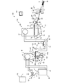
- FIG. 1 is a diagram schematically illustrating a sheet manufacturing apparatus 100 according to the present embodiment.
- the sheet manufacturing apparatus 100 includes a supply unit 10, a manufacturing unit 102, and a control unit 140, as shown in FIG.
- the manufacturing unit 102 manufactures a sheet.
- the manufacturing unit 102 includes a crushing unit 12, a defibrating unit 20, a sorting unit 40, a first web forming unit 45, a mixing unit 50, a depositing unit 60, a second web forming unit 70, and sheet formation. It has a part 80 and a cutting part 90.
- the supply unit 10 supplies raw materials to the crushing unit 12.
- the supply unit 10 is, for example, an automatic input unit for continuously supplying raw materials to the crushing unit 12.
- the raw material supplied by the supply part 10 contains fibers, such as a used paper and a pulp sheet, for example.
- the coarse crushing unit 12 cuts the raw material supplied by the supply unit 10 into pieces by cutting in air.
- the shape and size of the strip is, for example, a strip of several cm square.
- the crushing unit 12 has a crushing blade 14, and the charged raw material can be cut by the crushing blade 14.
- a shredder is used, for example.
- the raw material cut by the crushing unit 12 is received by the hopper 1 and then transferred (conveyed) to the defibrating unit 20 through the pipe 2.
- the defibrating unit 20 defibrates the raw material cut by the crushing unit 12.
- “defibration” means unraveling a raw material (a material to be defibrated) formed by binding a plurality of fibers into individual fibers.
- the defibrating unit 20 also has a function of separating substances such as resin particles, ink, toner, and a bleeding inhibitor adhering to the raw material from the fibers.
- the “defibrated material” includes resin particles (resins that bind multiple fibers together), ink, toner, etc. In some cases, additives such as colorants, anti-bleeding materials, and paper strength enhancing agents are included.
- the shape of the defibrated material that has been unraveled is a string shape or a ribbon shape.
- the unraveled defibrated material may exist in an unentangled state (independent state) with other undisentangled fibers, or entangled with other undisentangled defibrated material to form a lump. It may exist in a state (a state forming a so-called “dama”).
- the defibrating unit 20 performs defibration in a dry manner in the atmosphere (in the air). Specifically, an impeller mill is used as the defibrating unit 20.
- the defibrating unit 20 has a function of generating an air flow that sucks the raw material and discharges the defibrated material. As a result, the defibrating unit 20 can suck the raw material together with the airflow from the introduction port 22 with the airflow generated by itself, defibrate, and transport the defibrated material to the discharge port 24.
- the defibrated material that has passed through the defibrating unit 20 is transferred to the sorting unit 40 via the tube 3.
- the sorting unit 40 introduces the defibrated material defibrated by the defibrating unit 20 from the inlet 42 and sorts the defibrated material according to the length of the fiber.
- the selection unit 40 for example, a sieve is used.
- the sorting unit 40 has a net (filter, screen), fibers or particles smaller than the mesh size of the mesh (things that pass through the mesh, the first selection product), fibers larger than the mesh size of the mesh, Undefibrated pieces and lumps (those that do not pass through the net, second sort) can be separated.
- the first selection is received by the hopper 6 and then transferred to the mixing unit 50 via the pipe 7.
- the second selected item is returned to the defibrating unit 20 from the discharge port 44 through the pipe 8.
- the sorting unit 40 is a cylindrical sieve that can be rotated by a motor.
- a metal net for example, an expanded metal obtained by extending a cut metal plate, or a punching metal in which a hole is formed in the metal plate by a press machine or the like is used.
- the first web forming unit 45 conveys the first sorted product that has passed through the sorting unit 40 to the mixing unit 50.
- the first web forming unit 45 includes a mesh belt 46, a stretching roller 47, and a suction unit (suction mechanism) 48.
- the suction unit 48 can suck the first sorted material dispersed in the air through the opening (opening of the mesh) of the sorting unit 40 onto the mesh belt 46.
- the first selection is deposited on the moving mesh belt 46 to form the web V.
- the basic configurations of the mesh belt 46, the stretching roller 47, and the suction unit 48 are the same as the mesh belt 72, the stretching roller 74, and the suction mechanism 76 of the second web forming unit 70 described later.
- the web V is formed in a soft and swelled state containing a lot of air by passing through the sorting unit 40 and the first web forming unit 45.
- the web V deposited on the mesh belt 46 is put into the tube 7 and conveyed to the mixing unit 50.
- the mixing unit 50 mixes the first sorted product that has passed through the sorting unit 40 (the first sorted product conveyed by the first web forming unit 45) and the additive containing resin.
- the mixing unit 50 includes an additive supply unit 52 that supplies the additive, a pipe 54 that conveys the first selected product and the additive, and a blower 56.
- the additive is supplied from the additive supply unit 52 to the pipe 54 via the hopper 9.
- the tube 54 is continuous with the tube 7.
- the mechanism which mixes a 1st selection material and an additive is not specifically limited, It may stir with the blade
- the additive supply unit 52 As the additive supply unit 52, a screw feeder as shown in FIG. 1 or a disk feeder (not shown) is used.
- the additive supplied from the additive supply unit 52 includes a resin for binding a plurality of fibers. At the time when the resin is supplied, the plurality of fibers are not bound. The resin melts when passing through the sheet forming portion 80 and binds a plurality of fibers.
- the resin supplied from the additive supply unit 52 is a thermoplastic resin or a thermosetting resin.
- a thermoplastic resin or a thermosetting resin for example, AS resin, ABS resin, polypropylene, polyethylene, polyvinyl chloride, polystyrene, acrylic resin, polyester resin, polyethylene terephthalate, Polyphenylene ether, polybutylene terephthalate, nylon, polyamide, polycarbonate, polyacetal, polyphenylene sulfide, polyether ether ketone, and the like. These resins may be used alone or in combination.
- the additive supplied from the additive supply unit 52 may be fibrous or powdery.
- the additive supplied from the additive supply unit 52 prevents coloring of the fibers and the aggregation of the fibers depending on the type of sheet to be produced.
- a flame retardant for preventing the coagulation inhibitor suppressant soot, fibers, and the like from burning easily may be included.
- the mixture (mixture of the first selection product and the additive) that has passed through the mixing unit 50 is transferred to the deposition unit 60 via the pipe 54.
- the deposition unit 60 introduces the mixture that has passed through the mixing unit 50 from the introduction port 62, loosens the entangled defibrated material (fibers), and lowers it while dispersing it in the air. Furthermore, when the additive resin supplied from the additive supply unit 52 is fibrous, the deposition unit 60 loosens the entangled resin. Thereby, the deposition unit 60 can deposit the mixture on the second web forming unit 70 with good uniformity.
- Rotating cylindrical sieve is used as the accumulation unit 60.
- the deposition unit 60 has a net, and drops fibers or particles (those that pass through the net) included in the mixture that has passed through the mixing unit 50 that are smaller than the mesh opening size.
- the configuration of the deposition unit 60 is the same as the configuration of the sorting unit 40, for example.
- the “sieving” of the accumulation unit 60 may not have a function of selecting a specific object. That is, the “sieving” used as the depositing unit 60 means that the net is provided, and the depositing unit 60 may drop all of the mixture introduced into the depositing unit 60.
- the second web forming unit 70 deposits the passing material that has passed through the depositing unit 60 to form the web W.
- the second web forming unit 70 includes, for example, a mesh belt 72, a tension roller 74, and a suction mechanism 76.
- the mesh belt 72 accumulates the passing material that has passed through the opening (opening of the mesh) of the accumulation unit 60 while moving.
- the mesh belt 72 is stretched by a stretching roller 74, and is configured to allow air to pass therethrough.
- the mesh belt 72 moves as the stretching roller 74 rotates. While the mesh belt 72 continuously moves, the passing material that has passed through the accumulation portion 60 is continuously piled up, whereby the web W is formed on the mesh belt 72.
- the mesh belt 72 is made of, for example, metal, resin, cloth, or non-woven fabric.
- the suction mechanism 76 is provided below the mesh belt 72 (on the side opposite to the accumulation unit 60 side).
- the suction mechanism 76 can generate an air flow directed downward (air flow directed from the accumulation unit 60 toward the mesh belt 72).
- the suction mechanism 76 By the suction mechanism 76, the mixture dispersed in the air by the deposition unit 60 can be sucked onto the mesh belt 72. Thereby, the discharge speed from the deposition part 60 can be increased.
- the suction mechanism 76 can form a downflow in the dropping path of the mixture, and can prevent the defibrated material and additives from being entangled during the dropping.
- the web W in a soft and swelled state containing a large amount of air is formed.
- the web W deposited on the mesh belt 72 is conveyed to the sheet forming unit 80.
- a humidity control unit 78 that adjusts the humidity of the web W is provided.
- the humidity control unit 78 can adjust the amount ratio of the web W and water by adding water or water vapor to the web W.
- the sheet forming unit 80 forms the sheet S by pressurizing and heating the web W deposited on the mesh belt 72.
- the sheet forming unit 80 by heating the mixture of the defibrated material and the additive mixed in the web W, the plurality of fibers in the mixture are bound to each other via the additive (resin). Can do.
- the sheet forming unit 80 for example, a heating roller (heater roller), a hot press molding machine, a hot plate, a hot air blower, an infrared heater, or a flash fixing device is used.
- the sheet forming unit 80 includes a first binding unit 82 and a second binding unit 84, and the binding units 82 and 84 each include a pair of heating rollers 86. Since the binding portions 82 and 84 are configured as the heating roller 86, the web W is continuously conveyed as compared with the case where the binding portions 82 and 84 are configured as a plate-like press device (flat plate press device). Sheet S can be formed.
- the number of heating rollers 86 is not particularly limited.
- the cutting unit 90 cuts the sheet S formed by the sheet forming unit 80.
- the cutting unit 90 includes a first cutting unit 92 that cuts the sheet S in a direction that intersects the conveyance direction of the sheet S, and a second cutting unit 94 that cuts the sheet S in a direction parallel to the conveyance direction. ,have.
- the second cutting unit 94 cuts the sheet S that has passed through the first cutting unit 92, for example.
- a single-sheet sheet S having a predetermined size is formed.
- the cut sheet S is discharged to the discharge unit 96.
- the mesh belt 46 of the first web forming unit 45 collects at least a part of the defibrated material (the defibrated material selected by the selecting unit 40) conveyed from the defibrating unit 20 by the gas G1, and the defibrated unit.
- 20 is a mesh body that allows gas G1 from 20 to pass through.
- the mesh belt 46 is rotationally driven by the stretching roller 47 rotating.
- the suction part 48 of the first web forming part 45 sucks the gas G ⁇ b> 1 from the back side of the surface 46 a that collects the defibrated material of the mesh belt 46.
- the first web forming unit 45 has a pipe 145 that is continuous with the hopper 6.
- the tube 145 has a discharge port 145a through which the gas G1 that has passed through the mesh belt 46 is discharged. In this way, the gas G1 is discharged upstream of the depositing unit 60 (on the defibrating unit 20 side in the path from the defibrating unit 20 to the discharging unit 96 of the defibrated material in the sheet manufacturing apparatus 100).
- the first web forming unit 45 sets the size of the opening of the mesh belt 46 as appropriate, thereby adding relatively small (short) fibers, additives such as resin particles and colorants in the defibrated material.
- the gas G1 can be discharged from the discharge port 145a. Thereby, the ratio for which a comparatively large (long) fiber accounts in a defibrated material can be raised.
- the first web forming part 45 has a humidifying part 147 for humidifying the defibrated material collected by the mesh belt 46.
- the humidifying unit 147 directly adds water or water vapor to the web V (defibrated material) deposited on the mesh belt 46.
- the discharge port 147 a that discharges (injects) moisture from the humidifying unit 147 is disposed to face the mesh belt 46.
- the basic configuration of the humidifying unit 147 is the same as that of the humidity adjusting unit 78 described above.
- the pipe 7 into which the web V is thrown has an opening 7a.
- a defibrated material (web V) collected by the mesh belt 46 and a gas G2 different from the gas G1 are introduced.
- the opening 7 a is provided adjacent to the first web forming portion 45.
- the gas G2 is introduced into the opening 7a when the blower 56 of the mixing unit 50 is driven.
- the temperature of the gas G2 introduced from the opening 7a is lower than the temperature of the gas G1. This is because the gas G1 is warmed by the heat generated in the defibrating unit 20 and becomes high temperature.
- the temperature of the gas G1 is 10 ° C. or higher and 80 ° C. or lower
- the temperature of the gas G2 is 10 ° C. or higher and 40 ° C. or lower.
- the gases G1 and G2 are, for example, the atmosphere (air).
- the gas G2 may be introduced from outside the apparatus of the sheet manufacturing apparatus 100 or may be introduced from the inside of the apparatus, but the air inside the apparatus may be warmed by heat generated when the apparatus is driven. It is preferable to introduce from the outside.
- gas G1 and gas G2 are substantially the same temperature immediately after apparatus starting, if it drives continuously and heat
- the first web forming unit 45 separates at least a part of the gas G1 from the defibrating unit 20 and discharges it from the discharge port 145a, and introduces the defibrated material into the opening 7a.
- the mixing unit 50 introduces the gas G2 into the opening 7a, mixes the defibrated material and the gas G2, and conveys them to the deposition unit 60.
- the depositing unit 60 loosens the defibrated material introduced from the opening 7a and deposits it on the mesh belt 72
- the sheet forming unit 80 uses the defibrated material loosened by the accumulating unit 60 (introduced from the opening 7a).
- the sheet S is formed using the defibrated material.
- Control of the defibrating unit 20, the first web forming unit 45, the mixing unit 50, and the like may be performed by the control unit 140.
- the control unit 140 is, for example, a personal computer.
- the sheet manufacturing apparatus 100 has the following features, for example.
- the defibrated material conveyed by the gas G1 from the defibrating unit 20 is collected, the mesh body 46 that allows the gas G1 to pass through, the defibrated material collected by the mesh body 46, and the gas G1. And an opening 7a into which a gas G2 in a different state is introduced. Therefore, in the sheet manufacturing apparatus 100, the gas G1 dried at high temperature (high temperature and low humidity) by heat generated in the defibrating unit 20 is separated from the defibrated material, and the defibrated material is dried by the gas G2 different from the gas G1. It is possible to transport the defibrated material to the deposition unit 60 while suppressing this. Therefore, in the sheet manufacturing apparatus 100, it is possible to prevent the defibrated material from being dried and charged and attached to the apparatus. As a result, the sheet manufacturing apparatus 100 can manufacture the sheet S with a desired basis weight.
- the defibrated material adhering at a certain time is collected and accumulated on the mesh belt 72, and the thickness of the web W changes significantly to produce the sheet S with a desired basis weight. It may not be possible.
- the defibrated material adheres to the accumulation portion in this way it directly affects the basis weight of the sheet S. Therefore, in order to manufacture the sheet S with a desired basis weight, in particular, the defibration in the accumulation portion 60 is performed. It is preferable not to attach an object.
- the sheet manufacturing apparatus 100 it is possible to suppress the defibrated material from being dried and charged and adhered to the inside of the apparatus, so that the defibrated material in the sheet manufacturing apparatus is routed by the defibrated material adhered in the apparatus. Can be prevented from being blocked. Furthermore, the defibrated material adhering to the inside of the accumulation part becomes a dama, and the dampened defibrated material is deposited on the mesh belt, so that the sheet quality can be prevented from deteriorating.
- the above-described problems can be avoided by introducing the defibrated material collected by the mesh body 46 and the gas G2 different from the gas G1 into the opening 7a.
- the first web forming unit 45 can remove additives such as colorants contained in the defibrated material. That is, deinking can be performed in the first web forming unit 45. Therefore, the sheet manufacturing apparatus 100 does not need to be provided with a classification unit such as a cyclone, and accordingly, the cost can be reduced and the size can be reduced.
- the sheet manufacturing apparatus 100 has a discharge port 145a through which the gas G1 that has passed through the mesh body 46 is discharged. Therefore, in the sheet manufacturing apparatus 100, the gas G1 can be discharged out of the apparatus more reliably.
- the temperature of the gas G2 introduced from the opening 7a is lower than the temperature of the gas G1 from the defibrating unit 20. Therefore, in the sheet manufacturing apparatus 100, it can suppress more reliably that the defibrated material introduced from the opening 7a is dried and charged.
- the sheet manufacturing apparatus 100 includes a humidifying unit 147 that humidifies the defibrated material collected by the mesh body 46. Therefore, in the sheet manufacturing apparatus 100, the moisture of the defibrated material collected by the mesh body 46 can be adjusted, and the defibrated material collected by the mesh body 46 is more reliably dried and charged. Can be suppressed.
- the mesh body 46 is a mesh belt that is rotationally driven. Therefore, in the sheet manufacturing apparatus 100, the defibrated material can be introduced into the opening 7a by the mesh body 46.
- the sheet manufacturing apparatus 100 includes a suction unit 48 that sucks the gas G1 from the back side of the surface 46a that collects the defibrated material of the mesh body 46. Therefore, the sheet manufacturing apparatus 100 can more reliably remove additives such as colorants contained in the defibrated material.
- the sheet manufacturing apparatus 100 includes a sorting unit 40 that sorts the defibrated material defibrated by the defibrating unit 20. Therefore, in the sheet manufacturing apparatus 100, large fibers, undefibrated pieces, and lumps (those that do not pass through the screen of the sorting unit 40) can be returned to the defibrating unit 20.
- the sheet manufacturing method using the sheet manufacturing apparatus 100 at least a part of the gas G1 from the defibrating unit 20 is separated from the defibrated material, and the gas G2 and the defibrated material in a state different from the gas G1 are provided in the opening 7a. Introduce. Therefore, it can suppress that a defibrated material adheres in an apparatus.
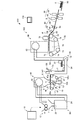
- FIG. 2 is a diagram schematically illustrating a sheet manufacturing apparatus 200 according to a first modification of the present embodiment.
- members having the same functions as those of the constituent members of the sheet manufacturing apparatus 100 according to the present embodiment are denoted by the same reference numerals, and detailed description thereof. Is omitted.
- the discharge port 147a of the humidifying unit 147 was disposed to face the mesh belt 46 (it was disposed above the mesh belt 46).
- the discharge port 147a of the humidifying unit 147 is disposed to face the opening 7a (disposed above the opening 7a).
- the humidifying unit 147 humidifies the gas G2 introduced from the opening 7a. Thereby, the defibrated material can be humidified.
- the position of the humidification unit 147 is not particularly limited.
- the humidification unit 147 may be provided in the tube 54.
- the humidifying unit 147 can adjust the moisture of the defibrated material by humidifying the gas G2 introduced from the opening 7a.
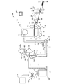
- FIG. 3 is a diagram schematically illustrating a sheet manufacturing apparatus 300 according to a second modification of the present embodiment.
- members having the same functions as those of the constituent members of the sheet manufacturing apparatus 100 according to the present embodiment are denoted by the same reference numerals, and detailed description thereof. Is omitted.
- the defibrated material that has passed through the defibrating unit 20 is transferred to the sorting unit 40 via the tube 3.
- the defibrated material that has passed through the defibrating unit 20 is transferred to the first web forming unit 45 via the tube 3.
- the sheet manufacturing apparatus 300 does not include the sorting unit 40.
- the defibrated material that has passed through the defibrating unit 20 is collected by the mesh belt 46 that moves in the vertical direction (the direction of gravity), and moves together with the mesh belt 46 (conveyed by the mesh belt 46). It is introduced into the opening 7a.
- the defibrated material collected in the mesh belt 46 is vertically adjusted by its own weight. It can be moved (dropped) in the direction. In this case, the mesh belt 46 may be stopped and a mechanism for rotating the mesh belt 46 may not be provided.
- the sheet manufacturing apparatus 300 may have a humidifying unit 147 as shown in FIGS. 1 and 2.
- the size can be reduced accordingly.
- the sheet S manufactured by the sheet manufacturing apparatus according to the present invention mainly refers to a sheet shape. However, it is not limited to a sheet shape, and may be a board shape or a web shape.
- the sheet in this specification is divided into paper and non-woven fabric.
- the paper includes a mode in which pulp or used paper is used as a raw material and is formed into a thin sheet, and includes recording paper for writing and printing, wallpaper, wrapping paper, colored paper, drawing paper, Kent paper, and the like.
- Non-woven fabrics are thicker or lower in strength than paper. General non-woven fabrics, fiber boards, tissue paper (cleaning tissue paper), kitchen paper, cleaners, filters, liquid (waste ink and oil) absorbents, sound absorbing materials, Insulating materials, cushioning materials, mats, etc.
- the raw material may be plant fibers such as cellulose, chemical fibers such as PET (polyethylene terephthalate) and polyester, and animal fibers such as wool and silk.
- a part of the configuration may be omitted within a range having the characteristics and effects described in the present application, or each embodiment or modification may be combined.
- the manufacturing unit 102 may omit a part of the configuration, add another configuration, or replace it with a known configuration as long as the sheet can be manufactured.
- the present invention includes substantially the same configuration (for example, a configuration having the same function, method and result, or a configuration having the same purpose and effect) as the configuration described in the embodiment.
- the invention includes a configuration in which a non-essential part of the configuration described in the embodiment is replaced.
- the present invention includes a configuration that exhibits the same operational effects as the configuration described in the embodiment or a configuration that can achieve the same object.
- the invention includes a configuration in which a known technique is added to the configuration described in the embodiment.
Landscapes
- Engineering & Computer Science (AREA)
- Life Sciences & Earth Sciences (AREA)
- Wood Science & Technology (AREA)
- Manufacturing & Machinery (AREA)
- Forests & Forestry (AREA)
- Textile Engineering (AREA)
- Mechanical Engineering (AREA)
- Nonwoven Fabrics (AREA)
- Dry Formation Of Fiberboard And The Like (AREA)
- Paper (AREA)
Priority Applications (3)
| Application Number | Priority Date | Filing Date | Title |
|---|---|---|---|
| CN201680012326.3A CN107250453B (zh) | 2015-03-04 | 2016-01-28 | 薄片制造装置以及薄片制造方法 |
| EP16758586.8A EP3266918B1 (en) | 2015-03-04 | 2016-01-28 | Sheet manufacturing device and sheet manufacturing method |
| US15/546,130 US10464232B2 (en) | 2015-03-04 | 2016-01-28 | Sheet manufacturing apparatus and sheet manufacturing method |
Applications Claiming Priority (2)
| Application Number | Priority Date | Filing Date | Title |
|---|---|---|---|
| JP2015042113A JP6589298B2 (ja) | 2015-03-04 | 2015-03-04 | シート製造装置およびシート製造方法 |
| JP2015-042113 | 2015-03-04 |
Publications (1)
| Publication Number | Publication Date |
|---|---|
| WO2016139885A1 true WO2016139885A1 (ja) | 2016-09-09 |
Family
ID=56846285
Family Applications (1)
| Application Number | Title | Priority Date | Filing Date |
|---|---|---|---|
| PCT/JP2016/000444 Ceased WO2016139885A1 (ja) | 2015-03-04 | 2016-01-28 | シート製造装置およびシート製造方法 |
Country Status (5)
| Country | Link |
|---|---|
| US (1) | US10464232B2 (enExample) |
| EP (1) | EP3266918B1 (enExample) |
| JP (1) | JP6589298B2 (enExample) |
| CN (1) | CN107250453B (enExample) |
| WO (1) | WO2016139885A1 (enExample) |
Cited By (1)
| Publication number | Priority date | Publication date | Assignee | Title |
|---|---|---|---|---|
| EP3482840A1 (en) * | 2017-11-08 | 2019-05-15 | Seiko Epson Corporation | Classifying device and fibrous feedstock recycling device |
Families Citing this family (11)
| Publication number | Priority date | Publication date | Assignee | Title |
|---|---|---|---|---|
| TW201700831A (zh) * | 2015-04-06 | 2017-01-01 | Seiko Epson Corp | 片材製造裝置及片材製造方法 |
| JP7006293B2 (ja) * | 2018-01-18 | 2022-01-24 | セイコーエプソン株式会社 | 繊維処理装置 |
| JP2019135333A (ja) * | 2018-02-05 | 2019-08-15 | セイコーエプソン株式会社 | 捕集装置、捕集方法、および、繊維原料再生装置 |
| CN110202904B (zh) * | 2018-02-28 | 2021-06-11 | 精工爱普生株式会社 | 料片形成装置以及薄片制造装置 |
| JP7218545B2 (ja) | 2018-11-08 | 2023-02-07 | セイコーエプソン株式会社 | ウェブ製造装置およびシート製造装置 |
| JP7275609B2 (ja) * | 2019-01-31 | 2023-05-18 | セイコーエプソン株式会社 | 分離装置および繊維体堆積装置 |
| JP2020121295A (ja) * | 2019-01-31 | 2020-08-13 | セイコーエプソン株式会社 | 分離装置および繊維体堆積装置 |
| JP7608981B2 (ja) * | 2021-06-28 | 2025-01-07 | セイコーエプソン株式会社 | 繊維体製造装置、繊維体製造ユニット、繊維体製造方法 |
| EP4367322B1 (de) * | 2021-07-08 | 2025-07-16 | Voith Patent GmbH | Herstellungsverfahren für airlaid-produkte |
| DE102021125451A1 (de) * | 2021-09-30 | 2023-03-30 | Voith Patent Gmbh | Verfahren und Maschine zur Herstellung einer Faserstoffbahn in einer Papiermaschine |
| DE102024130446B3 (de) * | 2024-10-21 | 2026-02-05 | Voith Patent Gmbh | Verfahren und Maschine zur Herstellung einer luftgelegten Faserstoffbahn |
Citations (4)
| Publication number | Priority date | Publication date | Assignee | Title |
|---|---|---|---|---|
| JPH0241202A (ja) * | 1988-08-02 | 1990-02-09 | Takehiro:Kk | 車両用インシュレータにおけるパッド材の製法 |
| JPH04504233A (ja) * | 1989-03-20 | 1992-07-30 | ウェヤーハウザー・カンパニー | 熱硬化性バインダー材料で被覆された天然繊維製品 |
| JP2004339653A (ja) * | 2003-05-16 | 2004-12-02 | Araco Corp | 繊維集合体の製造方法および繊維堆積装置 |
| WO2015049817A1 (ja) * | 2013-10-01 | 2015-04-09 | セイコーエプソン株式会社 | シート製造装置およびシートの製造方法 |
Family Cites Families (9)
| Publication number | Priority date | Publication date | Assignee | Title |
|---|---|---|---|---|
| US4268340A (en) * | 1973-08-05 | 1981-05-19 | Colgate-Palmolive Company | Method of forming an absorbent article |
| SE461962B (sv) | 1987-12-16 | 1990-04-23 | Sunds Defibrator Ind Ab | Saett och anordning foer framstaellning av fiberboardskivor |
| JP2002520513A (ja) * | 1998-07-14 | 2002-07-09 | エム アンド ジェイ ファイバーテック アー/エス | ニット分離装置 |
| DE60112204T2 (de) * | 2000-09-08 | 2006-05-24 | Japan Vilene Co., Ltd. | Vliesstoff aus feinen dispergierten Fasern, Verfahren und Vorrichtung zu deren Herstellung und dieses enthaltendes bahnförmiges Material |
| JP5720255B2 (ja) | 2011-01-12 | 2015-05-20 | セイコーエプソン株式会社 | 紙再生装置及び紙再生方法 |
| US8882965B2 (en) | 2011-01-12 | 2014-11-11 | Seiko Epson Corporation | Paper recycling system and paper recycling method |
| JP2014208923A (ja) * | 2013-03-27 | 2014-11-06 | セイコーエプソン株式会社 | シート製造装置 |
| JP6393998B2 (ja) * | 2013-03-27 | 2018-09-26 | セイコーエプソン株式会社 | シート製造装置、シート製造装置の制御方法 |
| JP6439929B2 (ja) * | 2015-02-06 | 2018-12-19 | セイコーエプソン株式会社 | シート製造装置及びシート製造方法 |
-
2015
- 2015-03-04 JP JP2015042113A patent/JP6589298B2/ja active Active
-
2016
- 2016-01-28 EP EP16758586.8A patent/EP3266918B1/en active Active
- 2016-01-28 CN CN201680012326.3A patent/CN107250453B/zh active Active
- 2016-01-28 US US15/546,130 patent/US10464232B2/en active Active
- 2016-01-28 WO PCT/JP2016/000444 patent/WO2016139885A1/ja not_active Ceased
Patent Citations (4)
| Publication number | Priority date | Publication date | Assignee | Title |
|---|---|---|---|---|
| JPH0241202A (ja) * | 1988-08-02 | 1990-02-09 | Takehiro:Kk | 車両用インシュレータにおけるパッド材の製法 |
| JPH04504233A (ja) * | 1989-03-20 | 1992-07-30 | ウェヤーハウザー・カンパニー | 熱硬化性バインダー材料で被覆された天然繊維製品 |
| JP2004339653A (ja) * | 2003-05-16 | 2004-12-02 | Araco Corp | 繊維集合体の製造方法および繊維堆積装置 |
| WO2015049817A1 (ja) * | 2013-10-01 | 2015-04-09 | セイコーエプソン株式会社 | シート製造装置およびシートの製造方法 |
Non-Patent Citations (1)
| Title |
|---|
| See also references of EP3266918A4 * |
Cited By (2)
| Publication number | Priority date | Publication date | Assignee | Title |
|---|---|---|---|---|
| EP3482840A1 (en) * | 2017-11-08 | 2019-05-15 | Seiko Epson Corporation | Classifying device and fibrous feedstock recycling device |
| US11072887B2 (en) | 2017-11-08 | 2021-07-27 | Seiko Epson Corporation | Classifying device and fibrous feedstock recycling device |
Also Published As
| Publication number | Publication date |
|---|---|
| JP2016160562A (ja) | 2016-09-05 |
| CN107250453A (zh) | 2017-10-13 |
| JP6589298B2 (ja) | 2019-10-16 |
| US20180021976A1 (en) | 2018-01-25 |
| EP3266918A4 (en) | 2018-07-25 |
| US10464232B2 (en) | 2019-11-05 |
| EP3266918A1 (en) | 2018-01-10 |
| CN107250453B (zh) | 2020-07-07 |
| EP3266918B1 (en) | 2020-10-28 |
Similar Documents
| Publication | Publication Date | Title |
|---|---|---|
| JP6589298B2 (ja) | シート製造装置およびシート製造方法 | |
| TWI652390B (zh) | Sheet manufacturing device | |
| JP6604428B2 (ja) | シート製造装置 | |
| CN107254792A (zh) | 薄片制造装置以及薄片的制造方法 | |
| JP2020109226A (ja) | シート製造装置、及び、シート製造装置の制御方法 | |
| JP2016141031A (ja) | シート製造装置およびシート製造方法 | |
| JP6617405B2 (ja) | シート製造装置およびシート製造方法 | |
| JP7003422B2 (ja) | シート、シート製造装置、及びシート製造方法 | |
| WO2018043030A1 (ja) | シート製造装置、及び、シート製造装置の制御方法 | |
| JP2016112740A (ja) | シート製造装置 | |
| US20170225173A1 (en) | Sheet manufacturing apparatus, paper supplying device, and paper shredding device | |
| WO2017043066A1 (ja) | シート製造装置およびシート製造方法 | |
| WO2018092626A1 (ja) | 気化式加湿ユニット、気化式加湿ユニットの制御方法、及びシート製造装置 | |
| JP2017013264A (ja) | シート製造装置 | |
| JP2016160561A (ja) | シート製造装置及びシート製造方法 | |
| JP2017008426A (ja) | シート製造装置 | |
| JP6497512B2 (ja) | シート製造装置及びシート製造方法 | |
| WO2018100979A1 (ja) | シート製造装置 | |
| JP6804837B2 (ja) | シート製造装置 | |
| JP6759558B2 (ja) | シート製造装置、紙供給装置、紙細断装置 | |
| JP2016065339A (ja) | シート製造装置、シート製造方法 | |
| JP2024117949A (ja) | 集塵装置の制御方法 | |
| WO2018043216A1 (ja) | 搬送装置、シート製造装置 |
Legal Events
| Date | Code | Title | Description |
|---|---|---|---|
| 121 | Ep: the epo has been informed by wipo that ep was designated in this application |
Ref document number: 16758586 Country of ref document: EP Kind code of ref document: A1 |
|
| WWE | Wipo information: entry into national phase |
Ref document number: 15546130 Country of ref document: US |
|
| REEP | Request for entry into the european phase |
Ref document number: 2016758586 Country of ref document: EP |
|
| NENP | Non-entry into the national phase |
Ref country code: DE |