WO2018092626A1 - 気化式加湿ユニット、気化式加湿ユニットの制御方法、及びシート製造装置 - Google Patents
気化式加湿ユニット、気化式加湿ユニットの制御方法、及びシート製造装置 Download PDFInfo
- Publication number
- WO2018092626A1 WO2018092626A1 PCT/JP2017/039968 JP2017039968W WO2018092626A1 WO 2018092626 A1 WO2018092626 A1 WO 2018092626A1 JP 2017039968 W JP2017039968 W JP 2017039968W WO 2018092626 A1 WO2018092626 A1 WO 2018092626A1
- Authority
- WO
- WIPO (PCT)
- Prior art keywords
- blower
- unit
- air
- amount
- vaporizing
- Prior art date
Links
Images


Classifications
-
- D—TEXTILES; PAPER
- D21—PAPER-MAKING; PRODUCTION OF CELLULOSE
- D21F—PAPER-MAKING MACHINES; METHODS OF PRODUCING PAPER THEREON
- D21F9/00—Complete machines for making continuous webs of paper
-
- D—TEXTILES; PAPER
- D21—PAPER-MAKING; PRODUCTION OF CELLULOSE
- D21G—CALENDERS; ACCESSORIES FOR PAPER-MAKING MACHINES
- D21G7/00—Damping devices
-
- D—TEXTILES; PAPER
- D04—BRAIDING; LACE-MAKING; KNITTING; TRIMMINGS; NON-WOVEN FABRICS
- D04H—MAKING TEXTILE FABRICS, e.g. FROM FIBRES OR FILAMENTARY MATERIAL; FABRICS MADE BY SUCH PROCESSES OR APPARATUS, e.g. FELTS, NON-WOVEN FABRICS; COTTON-WOOL; WADDING ; NON-WOVEN FABRICS FROM STAPLE FIBRES, FILAMENTS OR YARNS, BONDED WITH AT LEAST ONE WEB-LIKE MATERIAL DURING THEIR CONSOLIDATION
- D04H1/00—Non-woven fabrics formed wholly or mainly of staple fibres or like relatively short fibres
- D04H1/70—Non-woven fabrics formed wholly or mainly of staple fibres or like relatively short fibres characterised by the method of forming fleeces or layers, e.g. reorientation of fibres
- D04H1/72—Non-woven fabrics formed wholly or mainly of staple fibres or like relatively short fibres characterised by the method of forming fleeces or layers, e.g. reorientation of fibres the fibres being randomly arranged
- D04H1/732—Non-woven fabrics formed wholly or mainly of staple fibres or like relatively short fibres characterised by the method of forming fleeces or layers, e.g. reorientation of fibres the fibres being randomly arranged by fluid current, e.g. air-lay
-
- D—TEXTILES; PAPER
- D21—PAPER-MAKING; PRODUCTION OF CELLULOSE
- D21G—CALENDERS; ACCESSORIES FOR PAPER-MAKING MACHINES
- D21G9/00—Other accessories for paper-making machines
- D21G9/0009—Paper-making control systems
-
- F—MECHANICAL ENGINEERING; LIGHTING; HEATING; WEAPONS; BLASTING
- F24—HEATING; RANGES; VENTILATING
- F24F—AIR-CONDITIONING; AIR-HUMIDIFICATION; VENTILATION; USE OF AIR CURRENTS FOR SCREENING
- F24F3/00—Air-conditioning systems in which conditioned primary air is supplied from one or more central stations to distributing units in the rooms or spaces where it may receive secondary treatment; Apparatus specially designed for such systems
- F24F3/12—Air-conditioning systems in which conditioned primary air is supplied from one or more central stations to distributing units in the rooms or spaces where it may receive secondary treatment; Apparatus specially designed for such systems characterised by the treatment of the air otherwise than by heating and cooling
- F24F3/14—Air-conditioning systems in which conditioned primary air is supplied from one or more central stations to distributing units in the rooms or spaces where it may receive secondary treatment; Apparatus specially designed for such systems characterised by the treatment of the air otherwise than by heating and cooling by humidification; by dehumidification
-
- F—MECHANICAL ENGINEERING; LIGHTING; HEATING; WEAPONS; BLASTING
- F24—HEATING; RANGES; VENTILATING
- F24F—AIR-CONDITIONING; AIR-HUMIDIFICATION; VENTILATION; USE OF AIR CURRENTS FOR SCREENING
- F24F6/00—Air-humidification, e.g. cooling by humidification
-
- F—MECHANICAL ENGINEERING; LIGHTING; HEATING; WEAPONS; BLASTING
- F24—HEATING; RANGES; VENTILATING
- F24F—AIR-CONDITIONING; AIR-HUMIDIFICATION; VENTILATION; USE OF AIR CURRENTS FOR SCREENING
- F24F6/00—Air-humidification, e.g. cooling by humidification
- F24F6/02—Air-humidification, e.g. cooling by humidification by evaporation of water in the air
- F24F6/04—Air-humidification, e.g. cooling by humidification by evaporation of water in the air using stationary unheated wet elements
-
- F—MECHANICAL ENGINEERING; LIGHTING; HEATING; WEAPONS; BLASTING
- F24—HEATING; RANGES; VENTILATING
- F24F—AIR-CONDITIONING; AIR-HUMIDIFICATION; VENTILATION; USE OF AIR CURRENTS FOR SCREENING
- F24F6/00—Air-humidification, e.g. cooling by humidification
- F24F6/12—Air-humidification, e.g. cooling by humidification by forming water dispersions in the air
Definitions
- the present invention relates to a vaporization type humidification unit, a control method for the vaporization type humidification unit, and a sheet manufacturing apparatus.
- Patent Document 1 As a control method for a vaporizing humidifier, the humidity set in advance and the current humidity detected by a humidity sensor that measures the humidity in the room to be humidified are used. Based on the difference, the vaporization type humidifier that controls the humidification amount by controlling the rotational speed of the blower so as to supply the necessary humidification amount and controlling the air volume has been known.
- the present invention has been made to solve at least a part of the problems described above, and can be realized as the following forms or application examples.
- a vaporization type humidification unit is connected to a vaporization unit that evaporates moisture, a first blower that sucks humidified air humidified by the vaporization unit, and the first blower.
- a transport pipe that transports exhaust from the first blower, a second blower that is connected to the transport pipe and exhausts the humidified air exhausted from the first blower to the outside, and a middle of the transport pipe
- An opening provided on the exhaust side of the second blower, a humidity detector installed on the exhaust side of the second blower, and a control unit for controlling the amount of air exhausted from the first blower and the second blower.
- the unit controls the amount of air exhausted from the second blower to a desired value, and controls the amount of air exhausted from the first blower based on the humidity detected by the humidity detecting unit.
- the air volume of the first blower is controlled based on the humidity detected by the humidity detector.
- the air volume of the first blower is varied, there is a difference between the air volume of the first blower and the air volume of the second blower, but the air volume that becomes the difference is taken in through outside air through the opening. It is adjusted by being released. Thereby, the air volume exhausted from the second blower is kept constant.
- the mixing ratio of the air discharged from the first blower and the outside air amount introduced from the opening is changed.
- the humidification amount can be controlled. That is, the humidification amount can be easily controlled in a state where the air volume discharged from the second blower is kept constant.
- the humidification amount is an amount that gives moisture to the air.
- a vaporizing humidifying unit includes a vaporizing unit that evaporates moisture, a first blower that exhausts air toward the vaporizing unit, and the vaporizing unit connected to the vaporizing unit.
- a transport pipe through which the air that has passed is transported; a second blower that is connected to the transport pipe and exhausts the exhaust from the vaporization section side to the outside; and an opening provided in the middle of the transport pipe;
- a humidity detection unit installed on the exhaust side of the second blower; and a control unit configured to control the amount of air exhausted from the first blower and the second blower.
- the control unit exhausts air from the second blower.
- the amount of air to be discharged is controlled to a desired value, and the amount of air exhausted from the first blower is controlled based on the humidity detected by the humidity detector.
- the air volume of the first blower is controlled based on the humidity detected by the humidity detector.
- the air volume of the first blower is varied, there is a difference between the air volume of the first blower and the air volume of the second blower, but the air volume that becomes the difference is taken in through outside air through the opening. It is adjusted by being released. Thereby, the air volume exhausted from the second blower is kept constant.
- the mixing ratio of the air discharged from the first blower and the outside air amount introduced from the opening is changed. Thereby, the humidification amount can be controlled. That is, the humidification amount can be easily controlled in a state where the air volume discharged from the second blower is kept constant.
- the vaporization unit includes a humidification filter.
- mounting the humidification filter increases the contact area with air. Therefore, water can be efficiently evaporated.
- the air volume of the first blower is reduced.
- the air volume reduced by the first blower is taken in through the opening, and the air volume exhausted from the second blower is kept constant.
- the humidification amount is reduced. Therefore, the humidity can be easily reduced to a predetermined humidity.
- control unit increases the air volume of the first blower when the humidity detected by the humidity detection unit is lower than a predetermined humidity.
- the second blower preferably reduces the amount of outside air taken in from the opening.
- the humidity detected by the humidity detector when the humidity detected by the humidity detector is lower than the predetermined humidity, the air volume of the first blower is increased. Then, the intake amount of the outside air corresponding to the air volume increased by the first blower decreases, and the air volume exhausted from the second blower is kept constant. And since the mixing ratio of the air taken in from outside air falls, the humidification amount increases the air exhausted from a 2nd blower. Accordingly, the humidity can be easily increased to a predetermined humidity.
- a control method of the vaporization type humidification unit includes a vaporization unit that evaporates moisture, a first blower that sucks humidified air humidified by the vaporization unit, and a connection to the first blower A transport pipe through which the exhaust from the first blower is transported, a second blower connected to the transport pipe and exhausting the humidified air exhausted from the first blower side toward the outside, and the transport An air volume exhausted from the second blower, comprising: an opening provided in the middle of the pipe; and a humidity detection unit provided on the exhaust side of the second blower. Is controlled to a desired value, and the amount of air exhausted from the first blower is controlled based on the humidity detected by the humidity detector.
- the air volume of the first blower is controlled based on the humidity detected by the humidity detector.
- the air volume of the first blower is varied, there is a difference between the air volume of the first blower and the air volume of the second blower, but the air volume that becomes the difference is taken in through outside air through the opening. It is adjusted by being released. Thereby, the air volume exhausted from the second blower is kept constant.
- the mixing ratio of the air discharged from the first blower and the outside air amount introduced from the opening is changed. Thereby, the humidification amount can be controlled. That is, the humidification amount can be easily controlled in a state where the air volume discharged from the second blower is kept constant.
- a vaporization type humidification unit is disposed on the upstream side or the downstream side of the vaporization unit in the air flow direction and the vaporization unit that evaporates and vaporizes moisture, and is humidified by the vaporization unit.
- a first blower that sends the humidified air
- a second blower that is disposed downstream of the first blower and that mixes and exhausts the humidified air sent from the first blower and the outside air
- the second blower Based on the humidity detection unit installed on the exhaust side of the 2 blower and the detection result of the humidity detection unit, the amount of air exhausted from the second blower is not changed, and the amount of air blown by the first blower is changed.
- a control unit for controlling the humidification amount.
- control method of the vaporization type humidification unit according to this application example is arranged on the upstream side or the downstream side of the vaporization unit in the direction of air flow, the vaporization unit for evaporating and evaporating moisture, A first blower for sending humidified air humidified by the vaporizing section; and a second blower arranged downstream of the first blower and mixing and exhausting the humidified air sent by the first blower and outside air.
- a control method of a vaporizing humidification unit comprising a blower, wherein the amount of air exhausted from the second blower is changed, and the amount of humidification is controlled by changing the amount of air blown by the first blower. It is characterized by.
- the amount of outside air to be mixed can be reduced and the humidification amount can be increased.
- the amount of outside air to be mixed can be increased, and the amount of humidification can be reduced.
- the humidification amount can be controlled in a state where the air volume discharged from the second blower is kept constant.
- the ventilation volume of a 1st blower is more than the ventilation volume of a 2nd blower, the humidified air from a 1st blower is exhausted from a 2nd blower as it is, without mixing with external air.
- a sheet manufacturing apparatus includes the vaporizing humidification unit described in the application example.
- the vaporizing humidification unit by mounting the vaporizing humidification unit, for example, an appropriate humidification amount is given in a state where the airflow is kept constant with respect to the raw material containing the fibers, the sheet accumulation portion, and the like. Therefore, it is possible to adjust the moisture content of the raw material without adversely affecting the conveying air and the sheet stacking part, and preventing the raw material containing fibers from staying due to the influence of charging or adhering the raw materials to each other. Thus, the density of the completed sheet can be prevented from becoming non-uniform.
- the vaporizing humidification unit humidifies a portion through which the sheet material or material passes.
- the vaporization type humidification unit can be charged by humidifying, for example, a portion through which a raw material or a coarsely crushed piece of raw material passes or a portion through which a defibrated material obtained by defibrating the raw material passes. Can be suppressed.
- FIG. 1 Schematic which shows the structure of the sheet manufacturing apparatus which concerns on embodiment.
- the schematic diagram which shows the structure of a vaporization type humidification unit.
- the block diagram which shows the structure of the control part of a vaporization type humidification unit.
- the flowchart which shows the control method of a vaporization type humidification unit.
- the schematic diagram which shows the structure of the vaporization type humidification unit which concerns on the modification 1. As shown in FIG.
- FIG. 1 is a schematic diagram illustrating a configuration of a sheet manufacturing apparatus according to an embodiment.
- the sheet manufacturing apparatus 100 according to the embodiment for example, after used fiber such as confidential paper as a raw material is defibrated and fiberized by dry process, and then pressurized, heated, and cut to obtain new paper. It is an apparatus suitable for manufacturing.
- the bonding strength and whiteness of paper products can be improved and functions such as color, fragrance and flame retardancy can be added according to the application. Or you may.
- functions such as color, fragrance and flame retardancy
- by controlling the density, thickness, and shape of the paper it is possible to manufacture paper of various thicknesses and sizes according to the application, such as A4 or A3 office paper, business card paper, and the like.
- the sheet manufacturing apparatus 100 includes a supply unit 10, a crushing unit 12, a defibrating unit 20, a sorting unit 40, a first web forming unit 45, a rotating body 49, a mixing unit 50, a deposition unit 60, a second web forming unit 70, A conveyance unit 79, a sheet forming unit 80, a cutting unit 90, and a control unit 110 are provided.
- the sheet manufacturing apparatus 100 is provided with a humidifying unit 210, 212 and a vaporizing humidifying unit 300 (300a, 300b, 300c, 300d in the present embodiment) for the purpose of humidifying the raw material and / or humidifying the space in which the raw material moves. 300e).
- the raw material includes a raw material before being fiberized and a raw material (material) that has been fiberized.
- the humidification parts 210 and 212 show the location where the air humidified by the mist type humidification unit is supplied.
- the mist type humidification unit has a water tray (not shown) that functions as a water tank for storing water, and a vibration part (not shown) that atomizes the water in the water tray, and supplies mist generated by the vibration part. To do.
- the supply unit 10 supplies raw materials to the crushing unit 12.
- the raw material from which the sheet manufacturing apparatus 100 manufactures a sheet may be anything as long as it contains fibers, and examples thereof include paper, pulp, pulp sheet, cloth including nonwoven fabric, and woven fabric. In the present embodiment, a configuration in which the sheet manufacturing apparatus 100 uses waste paper as a raw material is illustrated.
- the supply unit 10 may be configured to include, for example, a stacker that accumulates and accumulates used paper and an automatic input device that sends the used paper from the stacker to the crushing unit 12.
- the coarse crushing unit 12 cuts (crushes) the raw material supplied by the supply unit 10 with a coarse crushing blade 14 to obtain a coarse crushing piece.
- the rough crushing blade 14 cuts the raw material in the air (in the air) or the like.
- the crushing unit 12 includes, for example, a pair of crushing blades 14 that are cut with a raw material interposed therebetween, and a drive unit (not shown) that rotates the crushing blades 14, and can have a configuration similar to a so-called shredder. .
- the shape and size of the coarsely crushed pieces are arbitrary and may be suitable for the defibrating process in the defibrating unit 20.
- the crushing unit 12 cuts the raw material into a piece of paper having a size of 1 to several cm square or less.
- the crushing part 12 has a chute (also referred to as a hopper) 9 that receives the crushing pieces that are cut by the crushing blade 14 and fall.
- the chute 9 has, for example, a taper shape in which the width gradually decreases in the direction in which the coarsely crushed pieces flow (the traveling direction). Therefore, the chute 9 can receive many coarse fragments.
- the chute 9 is connected to a tube 2 communicating with the defibrating unit 20, and the tube 2 forms a conveying path for conveying the raw material (crushed pieces) cut by the crushing blade 14 to the defibrating unit 20. .
- the coarsely crushed pieces are collected by the chute 9 and transferred (conveyed) through the tube 2 to the defibrating unit 20.
- Humidified air is supplied by the vaporizing humidification unit 300a to the chute 9 or the vicinity of the chute 9 included in the crushing unit 12.
- tube 2 by static electricity can be suppressed.
- the crushed material cut by the pulverizing blade 14 is transferred to the defibrating unit 20 together with humidified (high humidity) air, the effect of suppressing adhesion of the defibrated material inside the defibrating unit 20 is also achieved. I can expect.
- the vaporizing humidifying unit 300a may be configured to supply humidified air to the coarse crushing blade 14 and to neutralize the raw material supplied by the supply unit 10. Moreover, you may neutralize electricity using an ionizer with the vaporization type humidification unit 300a.
- the defibrating unit 20 defibrates the crushed material cut by the crushing unit 12. Specifically, the defibrating unit 20 defibrates the raw material (crushed pieces) cut by the crushing unit 12 to generate a defibrated material.
- defibration means unraveling a raw material (a material to be defibrated) formed by binding a plurality of fibers into individual fibers.
- the defibrating unit 20 also has a function of separating substances such as resin particles, ink, toner, and a bleeding inhibitor adhering to the raw material from the fibers.
- the defibrated material includes resin (resin for binding multiple fibers), ink, toner, etc. separated from the fibers when the fibers are unwound
- resin resin for binding multiple fibers
- ink ink
- toner etc. separated from the fibers when the fibers are unwound
- additives such as colorants, anti-bleeding agents, paper strength enhancers and the like are included.
- the shape of the defibrated material that has been unwound is a string shape or a ribbon shape.
- the unraveled defibrated material may exist in an unentangled state (independent state) with other undisentangled fibers, or entangled with other undisentangled defibrated material to form a lump. It may exist in a state (a state forming a so-called “dama”).
- the defibrating unit 20 performs defibration by a dry method.
- performing a process such as defibration in the air such as the atmosphere (in the air) is referred to as a dry process.
- the defibrating unit 20 uses an impeller mill.
- the defibrating unit 20 includes a rotor (not shown) that rotates at high speed, and a liner (not shown) that is positioned on the outer periphery of the rotor.
- the coarsely crushed pieces cut by the coarse pulverization unit 12 are sandwiched between the rotor of the defibrating unit 20 and the liner and defibrated.
- the defibrating unit 20 generates an air flow by the rotation of the rotor. With this airflow, the defibrating unit 20 can suck the crushed pieces, which are raw materials, from the tube 2 and convey the defibrated material to the discharge port 24. The defibrated material is sent out from the discharge port 24 to the tube 3 and transferred to the sorting unit 40 through the tube 3.
- the defibrated material generated in the defibrating unit 20 is conveyed from the defibrating unit 20 to the sorting unit 40 by the air flow generated by the defibrating unit 20.
- the sheet manufacturing apparatus 100 includes a defibrating unit blower 26 that is an airflow generator, and the defibrated material is conveyed to the sorting unit 40 by the airflow generated by the defibrating unit blower 26.
- the defibrating unit blower 26 is attached to the pipe 3, sucks air from the defibrating unit 20 together with the defibrated material, and blows it to the sorting unit 40.
- the sorting unit 40 has an inlet 42 through which the defibrated material defibrated from the tube 3 by the defibrating unit 20 flows together with the airflow.
- the sorting unit 40 sorts the defibrated material to be introduced into the introduction port 42 according to the length of the fiber. Specifically, the sorting unit 40 uses a defibrated material having a size equal to or smaller than a predetermined size among the defibrated material defibrated by the defibrating unit 20 as a first selected material, and a defibrated material larger than the first selected material. Is selected as the second selection.
- the first selection includes fibers or particles
- the second selection includes, for example, large fibers, undefibrated pieces (crushed pieces that have not been sufficiently defibrated), and defibrated fibers agglomerated or entangled. Including tama etc.
- the sorting unit 40 includes a drum unit (sieving unit) 41 and a housing unit 43 that accommodates the drum unit 41.
- the drum portion 41 is a cylindrical sieve that is rotationally driven by a motor.
- the drum portion 41 has a net (filter, screen) and functions as a sieve. Based on the mesh, the drum unit 41 sorts a first selection smaller than the mesh opening (opening) and a second selection larger than the mesh opening.
- a metal net for example, a metal net, an expanded metal obtained by extending a cut metal plate, or a punching metal in which a hole is formed in the metal plate by a press machine or the like is used.
- the defibrated material introduced into the inlet 42 is sent into the drum portion 41 together with the air current, and the first selected material falls downward from the mesh of the drum portion 41 by the rotation of the drum portion 41.
- the second selection that cannot pass through the mesh of the drum portion 41 is caused to flow by the airflow flowing into the drum portion 41 from the introduction port 42, led to the discharge port 44, and sent out to the pipe 8.
- the pipe 8 connects the inside of the drum portion 41 and the pipe 2.
- the second selection flowed through the pipe 8 flows through the pipe 2 together with the coarsely crushed pieces cut by the coarse crushing section 12 and is guided to the introduction port 22 of the defibrating section 20. As a result, the second selection is returned to the defibrating unit 20 and defibrated.
- the first selection material selected by the drum unit 41 is dispersed in the air through the mesh of the drum unit 41 and is applied to the mesh belt 46 of the first web forming unit 45 located below the drum unit 41. Descent towards.
- the first web forming unit 45 has a mesh belt 46 on which defibrated material is deposited, and functions as a separating unit that separates removed material that is not used for the sheet S from the defibrated material.
- the first web forming unit 45 further includes a stretching roller 47 and a suction unit (suction mechanism) 48.
- the mesh belt 46 is an endless belt, is suspended by three stretching rollers 47, and is conveyed in the direction indicated by the arrow in the drawing by the movement of the stretching rollers 47.
- the surface of the mesh belt 46 is constituted by a net having openings of a predetermined size.
- fine particles having a size that passes through the meshes fall below the mesh belt 46, and fibers of a size that cannot pass through the meshes accumulate on the mesh belt 46, and mesh. It is conveyed along with the belt 46 in the direction of the arrow.
- the fine particles falling from the mesh belt 46 include those that are relatively small or low in density (resin particles, colorants, additives, etc.) among the defibrated materials, and the sheet manufacturing apparatus 100 does not use them for manufacturing the sheet S. It is a removed product.
- the mesh belt 46 moves at a constant speed V1 during the normal operation of manufacturing the sheet S.
- the normal operation is an operation excluding the start control and stop control of the sheet manufacturing apparatus 100 to be described later. More specifically, the sheet manufacturing apparatus 100 manufactures a sheet S having a desired quality. It points to while doing.
- the defibrated material that has been defibrated by the defibrating unit 20 is sorted into the first sorted product and the second sorted product by the sorting unit 40, and the second sorted product is returned to the defibrating unit 20. Further, the removed material is removed from the first selected material by the first web forming unit 45. The remainder obtained by removing the removed material from the first selection is a material suitable for manufacturing the sheet S, and this material is deposited on the mesh belt 46 to form the first web W1.
- the suction unit 48 sucks air from below the mesh belt 46.
- the suction part 48 is connected to the dust collecting part 27 via the pipe 23.
- the dust collection unit 27 separates the fine particles from the airflow.
- a collection blower 28 is installed downstream of the dust collection unit 27, and the collection blower 28 functions as a dust collection suction unit that sucks air from the dust collection unit 27. Further, the air discharged from the collection blower 28 is discharged out of the sheet manufacturing apparatus 100 through the pipe 29.
- the first web W1 is formed on the mesh belt 46 by depositing fibers obtained by removing the removed material from the first selected material.
- the suction of the collection blower 28 the formation of the first web W1 on the mesh belt 46 is promoted, and the removed material is quickly removed.
- Humidified air is supplied to the space including the drum portion 41 by the vaporizing humidifying unit 300b.
- the humidified air can humidify the first selection item inside the selection unit 40 and weaken the adhesion of the first selection item to the mesh belt 46 due to the electrostatic force. Therefore, it is possible to easily peel the first selected item from the mesh belt 46 and to prevent the first selected item from adhering to the rotating body 49 or the inner wall of the housing part 43 due to electrostatic force.
- the removal object can be efficiently sucked by the suction portion 48.
- the configuration for sorting and separating the first sorted product and the second sorted product is not limited to the sorting unit 40 including the drum unit 41.
- you may employ adopt the structure which classifies the defibrated material processed by the defibrating unit 20 with a classifier.
- the classifier for example, a cyclone classifier, an elbow jet classifier, or an eddy classifier can be used. If these classifiers are used, it is possible to sort and separate the first sort and the second sort.
- the above classifier can realize a configuration in which removed products including relatively small ones and low density ones (resin particles, colorants, additives, etc.) among the defibrated materials are separated and removed.
- removed products including relatively small ones and low density ones (resin particles, colorants, additives, etc.) among the defibrated materials are separated and removed.
- it is good also as a structure which removes the microparticles
- the second sorted product may be returned to the defibrating unit 20, the removed product is collected by the dust collecting unit 27, and the first sorted product excluding the removed product may be sent to the pipe 54. .
- air including mist is supplied by the humidifying unit 210 to the downstream side of the sorting unit 40.
- the mist that is fine particles of water generated by the humidifying unit 210 descends toward the first web W1 and supplies moisture to the first web W1. Thereby, the amount of moisture contained in the first web W1 is adjusted, and adsorption of fibers to the mesh belt 46 due to static electricity can be suppressed.
- the sheet manufacturing apparatus 100 includes a rotating body 49 that functions as a dividing unit that divides the first web W1 deposited on the mesh belt 46.
- the first web W ⁇ b> 1 is separated from the mesh belt 46 at a position where the mesh belt 46 is folded back by the stretching roller 47 and divided by the rotating body 49.
- the first web W1 is a soft material in which fibers are accumulated to form a web shape, and the rotating body 49 loosens the fibers of the first web W1 and processes it into a state in which the resin can be easily mixed by the mixing unit 50 described later. .
- the configuration of the rotating body 49 is arbitrary, but in the present embodiment, the rotating body 49 can have a rotating blade shape having a plate-shaped blade.
- the rotating body 49 is disposed at a position where the first web W1 peeled off from the mesh belt 46 and the blades are in contact with each other. Due to the rotation of the rotating body 49 (for example, the rotation in the direction indicated by the arrow R in the figure), the blade collides with the first web W ⁇ b> 1 that is peeled from the mesh belt 46 and is transported to generate the subdivided body P.
- the rotating body 49 is preferably installed at a position where the blades of the rotating body 49 do not collide with the mesh belt 46.
- the distance between the tip of the blade of the rotating body 49 and the mesh belt 46 can be set to 0.05 mm or more and 0.5 mm or less.
- the rotating body 49 causes the mesh belt 46 to be damaged without being damaged.
- One web W1 can be divided efficiently.
- the subdivided body P divided by the rotating body 49 descends inside the tube 7 and is transferred (conveyed) to the mixing unit 50 by the airflow flowing inside the tube 7. Further, humidified air is supplied to the space including the rotating body 49 by the vaporizing humidifying unit 300c. Thereby, the phenomenon that fibers are adsorbed by static electricity to the inside of the tube 7 and the blades of the rotating body 49 can be suppressed. In addition, since high-humidity air is supplied to the mixing unit 50 through the pipe 7, the influence of static electricity can also be suppressed in the mixing unit 50.
- the mixing unit 50 includes an additive supply unit 52 (resin supply unit) that supplies an additive containing a resin, a tube 54 that communicates with the tube 7 and flows an air stream including the subdivided body P, and a mixing blower 56.
- the subdivided body P is a fiber obtained by removing the removed material from the first sorted product that has passed through the sorting unit 40 as described above.
- the mixing unit 50 mixes an additive containing a resin with the fibers constituting the subdivided body P.
- an air flow is generated by the mixing blower 56, and is conveyed while mixing the subdivided body P and the additive in the pipe 54.
- the subdivided body P is loosened in the process of flowing through the inside of the tube 7 and the tube 54, and becomes a finer fiber.
- the additive supply unit 52 (resin container) is connected to a resin cartridge (not shown) that accumulates the additive, and supplies the additive inside the resin cartridge to the tube 54.
- the additive supply unit 52 temporarily stores an additive composed of fine powder or fine particles inside the resin cartridge.
- the additive supply unit 52 includes a discharge unit 52a (resin supply unit) that sends the additive once stored to the pipe 54.
- the discharge unit 52 a includes a feeder (not shown) that sends the additive stored in the additive supply unit 52 to the pipe 54, and a shutter (not shown) that opens and closes a pipeline that connects the feeder and the pipe 54. . When this shutter is closed, the pipe line or opening connecting the discharge part 52a and the pipe 54 is closed, and supply of the additive from the additive supply part 52 to the pipe 54 is cut off.
- the additive In the state where the feeder of the discharge unit 52a is not operating, the additive is not supplied from the discharge unit 52a to the tube 54. However, when a negative pressure is generated in the tube 54, the feeder of the discharge unit 52a is stopped. Even so, the additive may flow to the tube 54. By closing the discharge part 52a, the flow of such an additive can be reliably interrupted.
- the additive supplied by the additive supply unit 52 includes a resin for binding a plurality of fibers.
- Thermoplastic resin or thermosetting resin for example, AS resin, ABS resin, polypropylene, polyethylene, polyvinyl chloride, polystyrene, acrylic resin, polyester resin, polyethylene terephthalate, polyphenylene ether, polybutylene terephthalate, nylon, polyamide, polycarbonate Polyacetal, polyphenylene sulfide, polyether ether ketone, and the like.
- the additive may contain a single substance, may be a mixture, or may contain a plurality of types of particles each composed of a single substance or a plurality of substances.
- the additive may be in the form of a fiber or powder.
- the resin contained in the additive is melted by heating to bind a plurality of fibers. Accordingly, in a state where the resin is mixed with the fibers and not heated to a temperature at which the resin melts, the fibers are not bound to each other.
- the additive supplied by the additive supply unit 52 includes a colorant for coloring the fiber, fiber aggregation, and resin aggregation depending on the type of sheet to be manufactured. It may also contain a coagulation inhibitor for suppressing odor, and a flame retardant for making the fibers difficult to burn. Moreover, the additive which does not contain a colorant may be colorless or light enough to be considered colorless, or may be white.
- the subdivided body P descending the pipe 7 and the additive supplied by the additive supply unit 52 are sucked into the pipe 54 and pass through the inside of the mixing blower 56 due to the air flow generated by the mixing blower 56.
- the fibers constituting the subdivided body P and the additive are mixed by the air flow generated by the mixing blower 56 and / or the action of the rotating part such as the blades of the mixing blower 56, and this mixture (the first sort and the additive) ) Is transferred to the deposition section 60 through the tube 54.
- the mechanism which mixes a 1st selection material and an additive is not specifically limited, It may stir with the blade
- the deposition unit 60 deposits the defibrated material that has been defibrated by the defibrating unit 20. Specifically, the deposition unit 60 introduces the mixture that has passed through the mixing unit 50 from the introduction port 62, loosens the entangled defibrated material (fibers), and lowers it while dispersing it in the air. Furthermore, when the additive resin supplied from the additive supply unit 52 is fibrous, the deposition unit 60 loosens the entangled resin. Thereby, the deposition unit 60 can deposit the mixture on the second web forming unit 70 with good uniformity.
- the accumulation unit 60 includes a drum unit 61 and a housing unit 63 that accommodates the drum unit 61.
- the drum unit 61 is a cylindrical sieve that is rotationally driven by a motor.
- the drum portion 61 has a net (filter, screen) and functions as a sieve. Due to the mesh, the drum portion 61 allows fibers and particles having a smaller mesh opening (opening) to pass through and lowers the drum portion 61 from the drum portion 61.
- the configuration of the drum unit 61 is the same as the configuration of the drum unit 41, for example.
- the “sieving” of the drum unit 61 may not have a function of selecting a specific object. That is, the “sieving” used as the drum part 61 means a thing provided with a net, and the drum part 61 may drop all of the mixture introduced into the drum part 61.
- a second web forming unit 70 is disposed below the drum unit 61.
- the 2nd web formation part 70 accumulates the passage thing which passed the accumulation part 60, and forms the 2nd web W2.
- the 2nd web formation part 70 has the mesh belt 72, the roller 74, and the suction mechanism 76, for example.
- the mesh belt 72 is an endless belt, is suspended on a plurality of rollers 74, and is conveyed in the direction indicated by the arrow in the drawing by the movement of the rollers 74.
- the mesh belt 72 is made of, for example, metal, resin, cloth, or non-woven fabric.
- the surface of the mesh belt 72 is configured by a net having openings of a predetermined size.
- fine particles having a size that passes through the mesh drops to the lower side of the mesh belt 72, and fibers having a size that cannot pass through the mesh are deposited on the mesh belt 72.
- 72 is conveyed in the direction of the arrow.
- the mesh belt 72 moves at a constant speed V2.
- the mesh of the mesh belt 72 is fine and can be sized so that most of the fibers and particles descending from the drum portion 61 are not allowed to pass through.
- the suction mechanism 76 is provided below the mesh belt 72 (on the side opposite to the accumulation unit 60 side).
- the suction mechanism 76 includes a suction blower 77, and can generate an airflow directed downward in the suction mechanism 76, that is, an airflow directed from the accumulation portion 60 toward the mesh belt 72 by the suction force of the suction blower 77.
- the suction mechanism 76 sucks the mixture dispersed in the air by the deposition unit 60 onto the mesh belt 72. Thereby, formation of the 2nd web W2 on the mesh belt 72 can be accelerated
- the suction blower 77 (deposition suction unit) may discharge the air sucked from the suction mechanism 76 to the outside of the sheet manufacturing apparatus 100 through a collection filter (not shown). Alternatively, the air sucked by the suction blower 77 may be sent to the dust collecting unit 27 and the removed matter contained in the air sucked by the suction mechanism 76 may be collected.
- Humidified air is supplied to the space including the drum unit 61 by the vaporizing humidifying unit 300d.
- the humidified air can humidify the inside of the accumulation portion 60, suppress the adhesion of fibers and particles to the housing portion 63 due to electrostatic force, and quickly drop the fibers and particles onto the mesh belt 72, so Two webs W2 can be formed.
- the second web W2 containing a large amount of air and softly inflated is formed by passing through the depositing unit 60 and the second web forming unit 70 (web forming step).
- the second web W2 deposited on the mesh belt 72 is conveyed to the sheet forming unit 80.
- air containing mist is supplied by the humidifying unit 212 to the downstream side of the deposition unit 60.
- generates is supplied to the 2nd web W2, and the moisture content which the 2nd web W2 contains is adjusted.
- suction etc. of the fiber to the mesh belt 72 by static electricity can be suppressed.
- the sheet manufacturing apparatus 100 is provided with a transport unit 79 that transports the second web W2 on the mesh belt 72 to the sheet forming unit 80.
- the conveyance unit 79 includes, for example, a mesh belt 79a, a roller 79b, and a suction mechanism 79c.
- the suction mechanism 79c generates an air flow, sucks the second web W2, and adsorbs the second web W2 to the mesh belt 79a.
- the mesh belt 79a moves by the rotation of the roller 79b, and conveys the second web W2 to the sheet forming unit 80.
- the moving speed of the mesh belt 72 and the moving speed of the mesh belt 79a are the same, for example.
- the conveyance unit 79 peels and conveys the second web W2 formed on the mesh belt 72 from the mesh belt 72.
- the sheet forming unit 80 forms the sheet S from the deposit accumulated in the accumulation unit 60. Specifically, the sheet forming unit 80 forms the sheet S by pressurizing and heating the second web W ⁇ b> 2 (deposit) deposited on the mesh belt 72 and conveyed by the conveying unit 79. In the sheet forming unit 80, the fibers of the defibrated material included in the second web W2 and the additive are heated to bind the plurality of fibers in the mixture to each other via the additive (resin). .
- the sheet forming unit 80 includes a pressurizing unit 82 that pressurizes the second web W2 and a heating unit 84 that heats the second web W2 pressurized by the pressurizing unit 82.
- the pressurizing unit 82 includes a pair of calendar rollers 85 and presses the second web W2 with a predetermined nip pressure. The second web W2 is reduced in thickness by being pressurized, and the density of the second web W2 is increased.
- One of the pair of calendar rollers 85 is a driving roller driven by a motor (not shown), and the other is a driven roller.
- the calendar roller 85 is rotated by a driving force of a motor (not shown) and conveys the second web W ⁇ b> 2 having a high density by pressurization toward the heating unit 84.
- the heating unit 84 can be configured using, for example, a heating roller (heater roller), a hot press molding machine, a hot plate, a hot air blower, an infrared heater, and a flash fixing device.
- the heating unit 84 includes a pair of heating rollers 86.
- the heating roller 86 is heated to a preset temperature by a heater installed inside or outside.
- the heating roller 86 heats the second web W ⁇ b> 2 pressed by the calendar roller 85 to form the sheet S.
- one of the pair of heating rollers 86 is a driving roller driven by a motor (not shown), and the other is a driven roller.
- the heating roller 86 is rotated by a driving force of a motor (not shown) and conveys the heated sheet S toward the cutting unit 90.
- the number of the calender rollers 85 included in the pressing unit 82 and the number of the heating rollers 86 included in the heating unit 84 are not particularly limited.
- the cutting unit 90 cuts the sheet S formed by the sheet forming unit 80.
- the cutting unit 90 includes a first cutting unit 92 that cuts the sheet S in a direction that intersects the conveyance direction of the sheet S, and a second cutting unit 94 that cuts the sheet S in a direction parallel to the conveyance direction.
- the second cutting unit 94 cuts the sheet S that has passed through the first cutting unit 92, for example.
- Humidified air is supplied to the space including the cutting unit 90 by the vaporizing humidifying unit 300e. With this humid air, the sheet S can be humidified, and the moisture content of the sheet S can be adjusted.
- the discharge unit 96 includes a discharge tray for discharging sheets S of a predetermined size or a stacker for storing the sheets S.
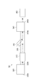
- FIG. 2 is a schematic diagram showing the configuration of the vaporizing humidifying unit 300.
- the vaporizing humidifying unit 300 is connected to a vaporizing unit 310 that evaporates moisture, a first blower 320 that sucks humidified air humidified by the vaporizing unit 310, and a first blower 320, and exhaust from the first blower 320 is exhausted.
- the control unit 110 of the present embodiment is also used as the control unit 110 of the sheet manufacturing apparatus 100.
- the vaporization unit 310 includes a humidification filter (not shown) and a water storage unit (not shown) for storing water in which the humidification filter is immersed. Air passes through the humidification filter to generate air with an increased amount of water vapor. To do. That is, the vaporizing unit 310 employs a vaporizing humidification method.
- the first blower 320 includes an intake port 320a that intakes the air that has passed through the vaporization unit 310, and an exhaust port 320b that exhausts the air downstream.
- the first blower 320 has an impeller and a motor that rotationally drives the impeller, and the rotational speed of the motor is controlled based on a command from the control unit 110. Thereby, the air volume exhausted from the first blower 320 is controlled.
- One end of the transfer pipe 330 is connected to the exhaust port 320 b of the first blower 320, and the other end of the transfer pipe 330 is connected to the intake port 340 a of the second blower 340. Exhaust gas from the first blower 320 is transported to the second blower 340 side via the transport pipe 330.
- the second blower 340 is connected to the transport pipe 330 and includes an intake port 340a for intake of exhaust from the first blower 320 side and an exhaust port 340b for exhausting outward.
- Second blower 340 includes an impeller and a motor that rotationally drives the impeller, and the number of rotations of the motor is controlled based on a command from control unit 110. Thereby, the air volume exhausted from the second blower 340 is controlled.
- An opening 350 is provided in the middle of the transfer pipe 330 between the first blower 320 and the second blower 340.
- the opening 350 communicates with the transport pipe 330.
- the conveyance pipe 330 communicates with the outside air.
- the form of the opening 350 is not limited, and a hole may be simply provided in the transport pipe 330, or the transport pipe 330 may be branched into a Y shape or a T shape. Further, the opening 350 may be extended in a tubular shape.
- the humidity detector 360 is installed on the exhaust side of the second blower 340 and detects the humidity of the exhaust destination of the second blower 340. For example, it is installed near the target member that receives the exhaust of the second blower 340.
- FIG. 3 is a block diagram showing the configuration of the control unit of the vaporizing humidifier unit.
- the controller 110 is connected to the humidity detector 360, the first blower 320, and the second blower 340.
- the control unit 110 is also connected to the supply unit 10, the crushing unit 12, the defibrating unit 20, the first web forming unit 45, the mixing unit 50, the second web forming unit 70, and the sheet forming unit 80 that have already been shown in FIG. However, the description is omitted here.
- the control unit 110 includes a CPU (not shown), a storage unit (ROM, RAM) (not shown), and a driver (not shown), and a humidity detection unit 360 is connected thereto.
- a control signal is output to the driver, and a drive signal is transmitted from the driver to the first blower 320 and the second blower 340.
- the air volume of the first blower 320 is changed based on the humidity detected by the humidity detector 360 while the air volume exhausted from the second blower 340 is kept constant. In a state in which is kept constant, an appropriate amount of humidification is applied to the crushing unit 12, the first web forming unit 45, the rotating body 49, the second web forming unit 70, and the cutting unit 90.
- control unit 110 outputs a control signal to the driver, and the air volume of the first blower 320 and the second blower 340, in other words, rotation of the motors built in the first blower 320 and the second blower 340. Control the number.
- the air volume of the first blower 320 is decreased, and the second blower 340 is opened to compensate for the air volume decreased by the first blower 320. Outside air is taken in from the unit 350 and exhausted with a constant air volume. If the humidity detected by the humidity detector 360 is lower than the predetermined humidity, the air volume of the first blower 320 is increased, and the increased air volume of the first blower 320 is taken in from outside air through the opening 350. The air volume is decreased and a constant air volume is exhausted from the second blower 340. When the air volume of the first blower 320 is larger than the air volume of the second blower 340, excess humidified air is released from the opening 350.
- the humidification amount can be controlled with a constant air volume.
- FIG. 4 is a flowchart showing a control method of the vaporizing humidifier unit.
- the air volume exhausted from the first blower 320 is changed based on the humidity detected by the humidity detecting unit 360 while keeping the air volume exhausted from the second blower 340 constant. Control.
- the rotational drive of the second blower 340 is controlled to be constant (the air volume is constant).
- step S11 the humidity is acquired. Specifically, the control unit 110 calculates the humidity based on the detection signal from the humidity detection unit 360.
- step S12 the calculated humidity is compared with a predetermined humidity set in advance, and it is determined whether or not the calculated humidity is within a predetermined humidity range set in advance. Then, when the calculated humidity is within the predetermined humidity range, it is determined as Yes, and the process proceeds to step S11.
- step S13 it is determined whether or not the calculated humidity is higher than a predetermined humidity range. If the calculated humidity is higher than the predetermined humidity range, it is determined Yes and the process proceeds to step S14.
- step S14 the control unit 110 controls the driving rotation of the motor to reduce the air volume of the first blower 320. At this time, the amount of the outside air reduced by the first blower 320 is taken in through the opening 350 and exhausted from the second blower 340.
- the mixing ratio between the amount of air discharged from the first blower 320 and the amount of outside air introduced through the opening 350 is varied while the amount of air discharged from the second blower 340 remains constant. To increase. Therefore, the amount of humidification can be reduced and the humidity of the air exhausted from the second blower 340 can be lowered.
- step S15 if the humidity detected by the humidity detection unit 360 is not higher than the predetermined humidity range, that is, if the calculated humidity is lower than the predetermined humidity range, it is determined as No, The process proceeds to step S15.
- step S15 the control unit 110 controls the drive rotation of the motor to increase the air volume of the first blower 320. At this time, the amount of outside air taken in through the opening 350 decreases by the amount of air increased by the first blower 320.
- the mixing ratio between the air discharged from the first blower 320 and the outside air amount introduced through the opening 350 is varied while the air amount exhausted from the second blower 340 is constant, and the ratio of the outside air amount Decrease. Therefore, the humidification amount can be increased and the humidity of the air exhausted from the second blower 340 can be increased.
- the air flow rate of the exhaust from the second blower 340 is constant, and the air flow rate of the first blower 320 is varied to discharge from the first blower 320.
- the mixing ratio between the air to be introduced and the amount of outside air introduced from the opening 350 is varied.
- the humidification amount can be controlled. That is, the humidification amount can be easily controlled in a state where the air amount discharged from the second blower 340 is kept constant. Furthermore, since the humidification amount can be changed in a short time just by changing the air volume of the first blower 320, it is possible to control the humidification amount with good responsiveness.
- the air volume is kept constant. It is possible to moderately humidify the material, avoiding the retention of the fiber-containing raw material due to the influence of charging or the adhering of the raw materials without adversely affecting the conveying air and the sheet stacking portion, and the moisture content of the raw material. The amount can be adjusted. Thereby, non-uniformity of the density of the sheet can be suppressed.
- FIG. 5 is a schematic diagram showing a configuration of the vaporizing humidifying unit 301 according to the first modification.
- the first blower 320 sucks the air that has passed through the vaporization unit 310, but the configuration is not limited thereto.
- the vaporization type humidification unit 301 which concerns on the modification 1 is demonstrated.
- the same number is attached
- the vaporizing humidifying unit 301 is connected to the vaporizing unit 310 that evaporates moisture, the first blower 320 that exhausts air (intaken outside air) toward the vaporizing unit 310, and the vaporizing unit 310.
- a transport pipe 330 that transports the air that has passed through the vaporization section 310
- a second blower 340 that is connected to the transport pipe 330 and exhausts the exhaust from the vaporization section 310 toward the outside.
- An opening 350 provided; a humidity detector 360 installed on the exhaust side of the second blower 340; and a controller 110 that controls the amount of air exhausted from the first blower 320 and the second blower 340. ing.
- the air volume of the first blower 320 is varied, and the air volume exhausted from the second blower 340 is controlled to be constant, thereby maintaining the air volume constant.
- an appropriate amount of humidification is applied. Therefore, it is possible to adjust the moisture content of the raw material without adversely affecting the conveying air and the sheet stacking part, and preventing the raw material containing fibers from staying due to the influence of charging or adhering the raw materials to each other. Thus, non-uniformity of the sheet density can be suppressed.
- the opening 350 is not limited to the middle of the transport pipe 330, and the opening 350 may be provided in the vaporization unit 310. In that case, the opening 350 is installed on the side of the transport pipe 330 through which the humidified air is transported after passing through the humidifying filter. This eliminates the need for the opening 350 in the transfer pipe 330 between the first blower 320 and the second blower 340, simplifies the structure of the vaporizing humidification unit 300, and increases the degree of freedom of the shape of the transfer pipe 330. .
- a wind speed sensor is installed on the exhaust side of the second blower 340, and the second blower 340 has a constant air volume based on the detected wind speed so as to match the air volume of the first blower 320. You may control the rotation speed of the motor of 2 blowers.
- the following effects can be obtained in addition to the effects in the embodiment.
- the air volume of the first blower 320 is varied while the rotation speed of the motor of the second blower 340 is constant, the air volume of the exhaust from the second blower is changed. Even if it changes, the air volume can be kept constant. Therefore, the humidification amount can be easily controlled in a state where the air volume discharged from the second blower 340 is kept constant.
- a part of the configuration may be omitted within the range having the characteristics and effects described in the present application.
- the sheet manufacturing apparatus 100 may omit a part of the configuration, add another configuration, or replace it with a known configuration as long as the sheet can be manufactured.
- the present invention includes substantially the same configuration (for example, a configuration having the same function, method, and result, or a configuration having the same purpose and effect) as the configuration described in the embodiment and the modification.
- the invention includes a configuration in which a non-essential part of the configuration described in the embodiment is replaced.
- the present invention includes a configuration that achieves the same effect as the configuration described in the embodiment or a configuration that can achieve the same object.
- the invention includes a configuration in which a known technique is added to the configuration described in the embodiment.
- Deposition unit 61 ... Drum unit 62 ... Inlet port 63 ... Housing unit 70 ... Second web forming unit 72 ... Mesh belt 74 ... Roller 76 ... Suction mechanism 77 ... Suction blower 79 ... Conveying unit 79a ... mesh belt, 79b ... roller, 9c ... Suction mechanism, 80 ... Sheet forming part, 82 ... Pressurizing part, 84 ... Heating part, 85 ... Calender roller, 86 ... Heating roller, 90 ... Cutting part, 92 ... First cutting part, 94 ... Second cutting part 96 ... Discharging unit, 100 ... Sheet manufacturing apparatus, 110 ... Control unit, 210,212 ...
- Humidifying unit 300, 300a, 300b, 300c, 300d, 300e, 301 ... Vaporizing humidifying unit, 310 ... Vaporizing unit, 320 ... 1st blower, 330 ... conveying pipe, 340 ... 2nd blower, 350 ... opening, 360 ... humidity detection part.
Abstract
風量を変化させることなく加湿量のみを変化可能な気化式加湿ユニットを提供する。 気化式加湿ユニットは、水分を蒸発させる気化部と、前記気化部により加湿された加湿空気を吸気する第1ブロアーと、前記第1ブロアーに接続され、前記第1ブロアーからの排気が搬送される搬送管と、前記搬送管に接続され、前記第1ブロアー側から排気された前記加湿空気を外部に向けて排気する第2ブロアーと、前記搬送管の途中に設けられた開口部と、前記第2ブロアーの排気側に設置された湿度検出部と、前記第1ブロアーと前記第2ブロアーとから排気される風量を制御する制御部と、を備え、前記制御部は、前記第2ブロアーから排気される風量を所望の値に制御し、前記湿度検出部により検出された湿度に基づいて、前記第1ブロアーから排気される風量を制御する。
Description
本発明は、気化式加湿ユニット、気化式加湿ユニットの制御方法、及びシート製造装置に関する。
従来、例えば、特許文献1に記載されているように、気化式加湿器の制御方法として、あらかじめ設定された湿度と、加湿対象となる室内の湿度を測定する湿度センサーで検出された現在の湿度と、の差に基づいて、必要な加湿量を供給することができるように送風機の回転数を制御し、風量を制御することによって加湿量を制御する気化式加湿器が知られていた。
しかしながら、特許文献1に記載の気化式加湿器では、加湿量を制御するためには、風量を変化させる必要があった。このため、上記の加湿器を例えば空気搬送やエアレイド法を用いた乾式の古紙再生機に適用させた場合には、風量の変化が、材料の搬送空気や、エアレイド法を用いたシート形成部における材料の堆積分布に影響を与えて、出来上がったシートが不均一になってしまう恐れがあった。
本発明は、上述の課題の少なくとも一部を解決するためになされたものであり、以下の形態または適用例として実現することが可能である。
[適用例1]本適用例に係る気化式加湿ユニットは、水分を蒸発させる気化部と、前記気化部により加湿された加湿空気を吸気する第1ブロアーと、前記第1ブロアーに接続され、前記第1ブロアーからの排気が搬送される搬送管と、前記搬送管に接続され、前記第1ブロアー側から排気された前記加湿空気を外部に向けて排気する第2ブロアーと、前記搬送管の途中に設けられた開口部と、前記第2ブロアーの排気側に設置された湿度検出部と、前記第1ブロアーと前記第2ブロアーとから排気される風量を制御する制御部とを備え、前記制御部は前記第2ブロアーから排気される風量を所望の値に制御し、前記湿度検出部により検出された湿度に基づいて、前記第1ブロアーから排気される風量を制御することを特徴とする。
本適用例によれば、湿度検出部により検出された湿度に基づいて、第1ブロアーの風量が制御される。このとき、第1ブロアーの風量を可変させる場合には、第1ブロアーの風量と第2ブロアーの風量とに差分が生じるが、差分となる風量分は、開口部を介して外気が取り込まれたり放出されたりすることによって調整される。これにより、第2ブロアーから排気される風量は一定に保たれる。また、第1ブロアーの風量を可変させることにより、第1ブロアーから排出される空気と開口部から導入される外気量との混合比率が可変される。これにより、加湿量が制御可能となる。つまり、第2ブロアーから排出される風量を一定に保持した状態で、加湿量を容易に制御することができる。なお、加湿量は、空気に対して水分を与える量である。
[適用例2]本適用例に係る気化式加湿ユニットは、水分を蒸発させる気化部と、前記気化部に向けて空気を排気する第1ブロアーと、前記気化部に接続され、前記気化部を通過した空気が搬送される搬送管と、前記搬送管に接続され、前記気化部側からの排気を外部に向けて排気する第2ブロアーと、前記搬送管の途中に設けられた開口部と、前記第2ブロアーの排気側に設置された湿度検出部と、前記第1ブロアーと前記第2ブロアーとから排気される風量を制御する制御部とを備え、前記制御部は前記第2ブロアーから排気される風量を所望の値に制御し、前記湿度検出部により検出された湿度に基づいて、前記第1ブロアーから排気される風量を制御することを特徴とする。
本適用例によれば、湿度検出部により検出された湿度に基づいて、第1ブロアーの風量が制御される。このとき、第1ブロアーの風量を可変させる場合には、第1ブロアーの風量と第2ブロアーの風量とに差分が生じるが、差分となる風量分は、開口部を介して外気が取り込まれたり放出されたりすることによって調整される。これにより、第2ブロアーから排気される風量は一定に保たれる。また、第1ブロアーの風量を可変させることにより、第1ブロアーから排出される空気と開口部から導入される外気量との混合比率が可変される。これにより、加湿量が制御可能となる。つまり、第2ブロアーから排出される風量を一定に保持した状態で、加湿量を容易に制御することができる。
[適用例3]上記適用例に記載の気化式加湿ユニットにおいて、前記気化部は加湿フィルターを備えていることが好ましい。
本適用例によれば、加湿フィルターを搭載することによって、空気との接触面積が増加する。従って、効率よく水分を蒸発させることができる。
[適用例4]上記適用例に記載の気化式加湿ユニットにおいて、前記制御部は所定の湿度に対して前記湿度検出部による検出湿度が高い場合には、前記第1ブロアーの風量を減少させ、前記第2ブロアーは、前記開口部からの外気の取り込み量を増加させることが好ましい。
本適用例によれば、所定の湿度に対して湿度検出部の検出湿度が高い場合には、第1ブロアーの風量が減少される。そして、第1ブロアーで減少される風量分は開口部を介して外気が取り込まれ、第2ブロアーから排気される風量は一定に保持される。そして、第2ブロアーから排気される空気は、外気から取り込まれた空気の混合比率が高まるため、加湿量が低減される。従って、容易に所定の湿度まで湿度を低下させることができる。
[適用例5]上記適用例に記載の気化式加湿ユニットにおいて、前記制御部は、所定の湿度に対して前記湿度検出部による検出湿度が低い場合には、前記第1ブロアーの風量を増加させ、前記第2ブロアーは、前記開口部からの外気の取り込み量を減少させることが好ましい。
本適用例によれば、所定の湿度に対して湿度検出部の検出湿度が低い場合には、第1ブロアーの風量が増加される。そして、第1ブロアーで増加される風量分の外気の取り込み量が減少し、第2ブロアーから排気される風量は一定に保持される。そして、第2ブロアーから排気される空気は、外気から取り込まれた空気の混合比率が低下するため、加湿量が増加される。従って、容易に所定の湿度まで湿度を上昇させることができる。
[適用例6]本適用例に係る気化式加湿ユニットの制御方法は、水分を蒸発させる気化部と、前記気化部により加湿された加湿空気を吸気する第1ブロアーと、前記第1ブロアーに接続され、前記第1ブロアーからの排気が搬送される搬送管と、前記搬送管に接続され、前記第1ブロアー側から排気された前記加湿空気を外部に向けて排気する第2ブロアーと、前記搬送管の途中に設けられた開口部と、前記第2ブロアーの排気側に設置された湿度検出部と、を備えた気化式加湿ユニットの制御方法であって、前記第2ブロアーから排気される風量を所望の値に制御し、前記湿度検出部により検出された湿度に基づいて、前記第1ブロアーから排気される風量を制御することを特徴とする。
本適用例によれば、湿度検出部により検出された湿度に基づいて、第1ブロアーの風量が制御される。このとき、第1ブロアーの風量を可変させる場合には、第1ブロアーの風量と第2ブロアーの風量とに差分が生じるが、差分となる風量分は、開口部を介して外気が取り込まれたり放出されたりすることによって調整される。これにより、第2ブロアーから排気される風量は一定に保たれる。また、第1ブロアーの風量を可変させることにより、第1ブロアーから排出される空気と開口部から導入される外気量との混合比率が可変される。これにより、加湿量が制御可能となる。つまり、第2ブロアーから排出される風量を一定に保持した状態で、加湿量を容易に制御することができる。
[適用例7]本適用例に係る気化式加湿ユニットは、水分を蒸発気化させる気化部と、空気の流れ方向において、前記気化部よりも上流側または下流側に配置され、前記気化部により加湿された加湿空気を送る第1ブロアーと、前記第1ブロアーよりも下流側に配置され、前記第1ブロアーにより送られた前記加湿空気と外気とを混合して排気する第2ブロアーと、前記第2ブロアーの排気側に設置された湿度検出部と、前記湿度検出部の検出結果に基づいて、前記第2ブロアーから排気される風量は変えることなく、前記第1ブロアーによる送風量を変更することにより、加湿量を制御する制御部と、を有することを特徴とする。
[適用例8]また、本適用例に係る気化式加湿ユニットの制御方法は、水分を蒸発気化させる気化部と、空気の流れ方向において、前記気化部よりも上流側または下流側に配置され、前記気化部により加湿された加湿空気を送る第1ブロアーと、前記第1ブロアーよりも下流側に配置され、前記第1ブロアーにより送られた前記加湿空気と外気とを混合して排気する第2ブロアーと、を備えた気化式加湿ユニットの制御方法であって、前記第2ブロアーから排気される風量は変えることなく、前記第1ブロアーによる送風量を変更することにより、加湿量を制御することを特徴とする。
適用例7及び8によれば、第1ブロアーの送風量を増加させることにより、混合される外気の量が低減し、加湿量を増加させことができる。また、第1ブロアーの送風量を低減させることにより、混合される外気の量が増加し、加湿量を減少させることができる。このように、第2ブロアーから排出される風量を一定に保持した状態で、加湿量を制御することができる。なお、第1ブロアーの送風量が第2ブロアーの排風量以上の場合には、外気と混合されることなく、第1ブロアーからの加湿空気がそのまま第2ブロアーから排気される。
[適用例9]本適用例に係るシート製造装置は、上記適用例に記載の気化式加湿ユニットを有することを特徴とする。
本適用例によれば、気化式加湿ユニットの搭載により、例えば、繊維を含む原料やシート堆積部等に対して風量を一定に保持した状態で、適当な加湿量が付与される。従って、搬送空気やシート堆積部に悪影響を与えることなく、繊維を含む原料が帯電の影響により滞留したり、原料同士が付着したりすることを回避し、原料の水分量を調整することが可能となり、出来上がったシートの密度が不均一になることを抑制することができる。
[適用例10]上記適用例に記載のシート製造装置において、前記気化式加湿ユニットにより、シートの原料または材料が通過する部分を加湿することを特徴とする。
本適用例によれば、気化式加湿ユニットにより、例えば、原料や原料を粗砕した粗砕片が通過する部分や、原料を解繊した解繊物が通過する部分を加湿することにより、帯電に因る不具合を抑えることができる。
以下、本発明の実施形態について、図面を参照して説明する。なお、以下の各図においては、各層や各部材を認識可能な程度の大きさにするため、各層や各部材の尺度を実際とは異ならせしめている。
<シート製造装置>
図1は実施形態に係るシート製造装置の構成を示す概略図である。
まず、実施形態に係るシート製造装置100は、例えば、原料としての機密紙等の使用済みの古紙を乾式で解繊して繊維化した後、加圧、加熱、切断することによって、新しい紙を製造するのに好適な装置である。
図1は実施形態に係るシート製造装置の構成を示す概略図である。
まず、実施形態に係るシート製造装置100は、例えば、原料としての機密紙等の使用済みの古紙を乾式で解繊して繊維化した後、加圧、加熱、切断することによって、新しい紙を製造するのに好適な装置である。
繊維化された原料(材料)に、さまざまな添加物を混合することによって、用途に合わせて、紙製品の結合強度や白色度を向上したり、色、香り、難燃等の機能を付加したりしてもよい。また、紙の密度や厚さ、形状をコントロールして成形することで、A4やA3のオフィス用紙、名刺用紙等、用途に合わせて、さまざまな厚さ・サイズの紙を製造することができる。
シート製造装置100は、供給部10、粗砕部12、解繊部20、選別部40、第1ウェブ形成部45、回転体49、混合部50、堆積部60、第2ウェブ形成部70、搬送部79、シート形成部80、切断部90、及び、制御部110を備える。
シート製造装置100は、供給部10、粗砕部12、解繊部20、選別部40、第1ウェブ形成部45、回転体49、混合部50、堆積部60、第2ウェブ形成部70、搬送部79、シート形成部80、切断部90、及び、制御部110を備える。
また、シート製造装置100は、原料に対する加湿、及び/または原料が移動する空間を加湿する目的で、加湿部210,212と、気化式加湿ユニット300(本実施形態では300a、300b、300c、300d、300e)を備える。ここで原料には、繊維化される前の原料や繊維化された原料(材料)を含む。
また、加湿部210及び212は、ミスト式加湿ユニットによって加湿された空気が供給される箇所を示す。ミスト式加湿ユニットは、水を貯留する水槽として機能する水トレー(図示略)と、水トレイ内の水を霧化する振動部(図示略)とを有し、振動部により発生するミストを供給する。
また、加湿部210及び212は、ミスト式加湿ユニットによって加湿された空気が供給される箇所を示す。ミスト式加湿ユニットは、水を貯留する水槽として機能する水トレー(図示略)と、水トレイ内の水を霧化する振動部(図示略)とを有し、振動部により発生するミストを供給する。
供給部10は、粗砕部12に原料を供給する。シート製造装置100がシートを製造する原料は繊維を含むものであればよく、例えば、紙、パルプ、パルプシート、不織布を含む布、或いは織物等が挙げられる。本実施形態ではシート製造装置100が古紙を原料とする構成を例示する。供給部10は、例えば、古紙を重ねて蓄積するスタッカーと、スタッカーから古紙を粗砕部12に送り出す自動投入装置とを備える構成とすることができる。
粗砕部12は、供給部10によって供給された原料を粗砕刃14によって裁断(粗砕)して、粗砕片にする。粗砕刃14は、大気中(空気中)等の気中で原料を裁断する。粗砕部12は、例えば、原料を挟んで裁断する一対の粗砕刃14と、粗砕刃14を回転させる駆動部(図示略)とを備え、いわゆるシュレッダーと同様の構成とすることができる。粗砕片の形状や大きさは任意であり、解繊部20における解繊処理に適していればよい。例えば、粗砕部12は、原料を、1~数cm四方またはそれ以下のサイズの紙片に裁断する。
粗砕部12は、粗砕刃14により裁断されて落下する粗砕片を受けるシュート(ホッパーとも称する)9を有する。シュート9は、例えば、粗砕片が流れる方向(進行する方向)において、徐々に幅が狭くなるテーパー形状を有する。そのため、シュート9は、多くの粗砕片を受けとめることができる。
シュート9には、解繊部20に連通する管2が連結され、管2は粗砕刃14によって裁断された原料(粗砕片)を、解繊部20に搬送させるための搬送路を形成する。粗砕片はシュート9により集められ、管2を通って解繊部20に移送(搬送)される。
粗砕部12が有するシュート9、或いはシュート9の近傍には、気化式加湿ユニット300aにより加湿空気が供給される。これにより、粗砕刃14により裁断された粗砕物が、静電気によってシュート9や管2の内面に吸着する現象を抑制できる。また、粗砕刃14が裁断した粗砕物は、加湿された(高湿度の)空気とともに解繊部20に移送されるので、解繊部20の内部における解繊物の付着を抑制する効果も期待できる。
また、気化式加湿ユニット300aは、粗砕刃14に加湿空気を供給して、供給部10が供給する原料を除電する構成としてもよい。また、気化式加湿ユニット300aとともにイオナイザーを用いて除電してもよい。
解繊部20は、粗砕部12で裁断された粗砕物を解繊する。具体的には、解繊部20は、粗砕部12によって裁断された原料(粗砕片)を解繊処理し、解繊物を生成する。ここで、「解繊する」とは、複数の繊維が結着されてなる原料(被解繊物)を、繊維1本1本に解きほぐすことをいう。解繊部20は、原料に付着した樹脂粒やインク、トナー、にじみ防止剤等の物質を、繊維から分離させる機能も有する。
解繊部20を通過したものを「解繊物」という。「解繊物」には、解きほぐされた解繊物繊維の他に、繊維を解きほぐす際に繊維から分離した樹脂(複数の繊維同士を結着させるための樹脂)粒や、インク、トナー等の色剤や、にじみ防止剤、紙力増強剤等の添加剤を含んでいる場合もある。
解きほぐされた解繊物の形状は、ひも(string)状や平ひも(ribbon)状である。解きほぐされた解繊物は、他の解きほぐされた繊維と絡み合っていない状態(独立した状態)で存在してもよいし、他の解きほぐされた解繊物と絡み合って塊状となった状態(いわゆる「ダマ」を形成している状態)で存在してもよい。
解繊部20は、乾式で解繊を行う。ここで、大気中(空気中)等の気中において、解繊等の処理を行うことを乾式と称する。本実施形態では、解繊部20がインペラーミルを用いる構成とする。具体的には、解繊部20は、高速回転するローター(図示略)、及び、ローターの外周に位置するライナー(図示略)を備える。粗砕部12で裁断された粗砕片は、解繊部20のローターとライナーとの間に挟まれて解繊される。解繊部20は、ローターの回転により気流を発生させる。この気流により、解繊部20は、原料である粗砕片を管2から吸引し、解繊物を排出口24へと搬送できる。解繊物は排出口24から管3に送り出され、管3を介して選別部40に移送される。
このように、解繊部20で生成される解繊物は、解繊部20が発生する気流により解繊部20から選別部40に搬送される。さらに、シート製造装置100が気流発生装置である解繊部ブロアー26を備え、解繊部ブロアー26が発生する気流により解繊物が選別部40に搬送される。解繊部ブロアー26は管3に取り付けられ、解繊部20から解繊物とともに空気を吸引し、選別部40に送風する。
選別部40は、管3から解繊部20により解繊された解繊物が気流とともに流入する導入口42を有する。選別部40は、導入口42に導入する解繊物を、繊維の長さによって選別する。詳細には、選別部40は、解繊部20により解繊された解繊物のうち、予め定められたサイズ以下の解繊物を第1選別物とし、第1選別物より大きい解繊物を第2選別物として、選別する。第1選別物は繊維または粒子等を含み、第2選別物は、例えば、大きい繊維、未解繊片(十分に解繊されていない粗砕片)、解繊された繊維が凝集し、或いは絡まったダマ等を含む。
選別部40は、ドラム部(篩部)41と、ドラム部41を収容するハウジング部43と、を有する。ドラム部41は、モーターによって回転駆動される円筒の篩である。ドラム部41は、網(フィルター、スクリーン)を有し、篩(ふるい)として機能する。この網の目により、ドラム部41は、網の目開き(開口)の大きさより小さい第1選別物と、網の目開きより大きい第2選別物とを選別する。ドラム部41の網としては、例えば、金網、切れ目が入った金属板を引き延ばしたエキスパンドメタル、金属板にプレス機等で穴を形成したパンチングメタルを用いる。
導入口42に導入された解繊物は気流とともにドラム部41の内部に送り込まれ、ドラム部41の回転によって第1選別物がドラム部41の網の目から下方に落下する。ドラム部41の網の目を通過できない第2選別物は、導入口42からドラム部41に流入する気流により流されて排出口44に導かれ、管8に送り出される。
管8は、ドラム部41の内部と管2とを連結する。管8を通って流される第2選別物は、粗砕部12により裁断された粗砕片とともに管2を流れ、解繊部20の導入口22に導かれる。これにより、第2選別物は解繊部20に戻されて解繊処理される。
また、ドラム部41により選別される第1選別物は、ドラム部41の網の目を通って空気中に分散し、ドラム部41の下方に位置する第1ウェブ形成部45のメッシュベルト46に向けて降下する。
第1ウェブ形成部45は、解繊物が堆積するメッシュベルト46を有し、解繊物からシートSに使用されない除去物を分離する分離部として機能する。この第1ウェブ形成部45は、さらに、張架ローラー47と、吸引部(サクション機構)48と、を含む。
メッシュベルト46は無端形状のベルトであって、3つの張架ローラー47に懸架され、張架ローラー47の動きにより、図中矢印で示す方向に搬送される。メッシュベルト46の表面は所定サイズの開口が並ぶ網で構成される。
選別部40から降下する第1選別物のうち、網の目を通過するサイズの微粒子はメッシュベルト46の下方に落下し、網の目を通過できないサイズの繊維がメッシュベルト46に堆積し、メッシュベルト46とともに矢印方向に搬送される。メッシュベルト46から落下する微粒子は、解繊物の中で比較的小さいものや密度の低いもの(樹脂粒や色剤や添加剤等)を含み、シート製造装置100がシートSの製造に使用しない除去物である。
メッシュベルト46は、シートSを製造する通常動作中には、一定の速度V1で移動する。ここで、通常動作中とは、後述するシート製造装置100の始動制御、及び、停止制御の実行中を除く動作中であり、より詳細には、シート製造装置100が望ましい品質のシートSを製造している間を指す。
従って、解繊部20で解繊処理された解繊物は、選別部40で第1選別物と第2選別物とに選別され、第2選別物が解繊部20に戻される。また、第1選別物から、第1ウェブ形成部45によって除去物が除かれる。第1選別物から除去物を除いた残りは、シートSの製造に適した材料であり、この材料はメッシュベルト46に堆積して第1ウェブW1を形成する。
吸引部48は、メッシュベルト46の下方から空気を吸引する。吸引部48は、管23を介して集塵部27に連結される。集塵部27は、微粒子を気流から分離する。集塵部27の下流には、捕集ブロアー28が設置され、捕集ブロアー28は、集塵部27から空気を吸引する集塵用吸引部として機能する。また、捕集ブロアー28が排出する空気は管29を介してシート製造装置100の外に排出される。
この構成では、捕集ブロアー28により、集塵部27を通じて吸引部48から空気が吸引される。吸引部48では、メッシュベルト46の網の目を通過する微粒子が、空気とともに吸引され、管23を通って集塵部27に送られる。集塵部27は、メッシュベルト46を通過した微粒子を気流から分離して蓄積する。
従って、メッシュベルト46の上には第1選別物から除去物を除去した繊維が堆積して第1ウェブW1が形成される。捕集ブロアー28が吸引を行うことで、メッシュベルト46上における第1ウェブW1の形成が促進され、かつ、除去物が速やかに除去される。
ドラム部41を含む空間には、気化式加湿ユニット300bにより加湿空気が供給される。この加湿空気によって、選別部40の内部で第1選別物を加湿し、第1選別物の静電力によるメッシュベルト46への付着を弱めることができる。従って、第1選別物をメッシュベルト46から剥離し易くし、また、第1選別物が回転体49やハウジング部43の内壁に静電力によって付着することを抑制することができる。また、吸引部48によって除去物を効率よく吸引できる。
なお、シート製造装置100において、第1選別物と第2選別物とを選別し、分離する構成は、ドラム部41を備える選別部40に限定されない。例えば、解繊部20で解繊処理された解繊物を、分級機によって分級する構成を採用してもよい。分級機としては、例えば、サイクロン分級機、エルボージェット分級機、エディクラシファイヤーを用いることができる。これらの分級機を用いれば、第1選別物と第2選別物とを選別し、分離することが可能である。
さらに、上記の分級機により、解繊物の中で比較的小さいものや密度の低いもの(樹脂粒や色剤や添加剤等)を含む除去物を、分離して除去する構成を実現できる。例えば、第1選別物に含まれる微粒子を、分級機によって、第1選別物から除去する構成としてもよい。この場合、第2選別物は、例えば解繊部20に戻され、除去物は集塵部27により集塵され、除去物を除く第1選別物が管54に送られる構成とすることができる。
メッシュベルト46の搬送経路において、選別部40の下流側には、加湿部210によって、ミストを含む空気が供給される。加湿部210が生成する水の微粒子であるミストは、第1ウェブW1に向けて降下し、第1ウェブW1に水分を供給する。これにより、第1ウェブW1が含む水分量が調整され、静電気によるメッシュベルト46への繊維の吸着等を抑制できる。
シート製造装置100は、メッシュベルト46に堆積した第1ウェブW1を分断する分断部として機能する回転体49を備える。第1ウェブW1は、メッシュベルト46が張架ローラー47により折り返す位置で、メッシュベルト46から剥離して、回転体49により分断される。
第1ウェブW1は繊維が堆積してウェブ形状となった柔らかい材料であり、回転体49は、第1ウェブW1の繊維をほぐして、後述する混合部50で樹脂を混合しやすい状態に加工する。
回転体49の構成は任意であるが、本実施形態では、板状の羽根を有し回転する回転羽形状とすることができる。回転体49は、メッシュベルト46から剥離する第1ウェブW1と羽根とが接触する位置に配置される。回転体49の回転(例えば図中矢印Rで示す方向への回転)により、メッシュベルト46から剥離して搬送される第1ウェブW1に羽根が衝突して分断し、細分体Pを生成する。
回転体49は、回転体49の羽根がメッシュベルト46に衝突しない位置に設置されることが好ましい。例えば、回転体49の羽根の先端とメッシュベルト46との間隔を、0.05mm以上0.5mm以下とすることができ、この場合、回転体49によって、メッシュベルト46に損傷を与えることなく第1ウェブW1を効率よく分断できる。
回転体49によって分断された細分体Pは、管7の内部を下降して、管7の内部を流れる気流によって混合部50へ移送(搬送)される。
また、回転体49を含む空間には、気化式加湿ユニット300cにより加湿空気が供給される。これにより、管7の内部や、回転体49の羽根に対し、静電気により繊維が吸着する現象を抑制できる。また、管7を通って、湿度の高い空気が混合部50に供給されるので、混合部50においても静電気による影響を抑制できる。
また、回転体49を含む空間には、気化式加湿ユニット300cにより加湿空気が供給される。これにより、管7の内部や、回転体49の羽根に対し、静電気により繊維が吸着する現象を抑制できる。また、管7を通って、湿度の高い空気が混合部50に供給されるので、混合部50においても静電気による影響を抑制できる。
混合部50は、樹脂を含む添加物を供給する添加物供給部52(樹脂供給部)、管7に連通し、細分体Pを含む気流が流れる管54、及び、混合ブロアー56を備える。細分体Pは、上述のように選別部40を通過した第1選別物から除去物を除去した繊維である。
混合部50は、細分体Pを構成する繊維に、樹脂を含む添加物を混合する。
混合部50では、混合ブロアー56によって気流を発生させ、管54中において、細分体Pと添加物とを混合させながら、搬送する。また、細分体Pは、管7及び管54の内部を流れる過程でほぐされて、より細かい繊維状となる。
混合部50では、混合ブロアー56によって気流を発生させ、管54中において、細分体Pと添加物とを混合させながら、搬送する。また、細分体Pは、管7及び管54の内部を流れる過程でほぐされて、より細かい繊維状となる。
添加物供給部52(樹脂収容部)は、添加物を蓄積する樹脂カートリッジ(図示略)に接続され、樹脂カートリッジ内部の添加物を管54に供給する。添加物供給部52は、樹脂カートリッジ内部の微粉または微粒子からなる添加物をいったん貯留する。添加物供給部52は、一旦貯留した添加物を管54に送る排出部52a(樹脂供給部)を有する。
排出部52aは、添加物供給部52に貯留された添加物を管54に送出するフィーダー(図示略)、及び、フィーダーと管54とを接続する管路を開閉するシャッター(図示略)を備える。このシャッターを閉じると、排出部52aと管54とを連結する管路或いは開口が閉鎖され、添加物供給部52から管54への添加物の供給が絶たれる。
排出部52aのフィーダーが動作していない状態では、排出部52aから管54に添加物が供給されないが、管54内に負圧が発生した場合等には、排出部52aのフィーダーが停止していても添加物が管54に流れる可能性がある。排出部52aを閉じることにより、このような添加物の流れを確実に遮断できる。
添加物供給部52が供給する添加物は、複数の繊維を結着させるための樹脂を含む。熱可塑性樹脂や熱硬化性樹脂であり、例えば、AS樹脂、ABS樹脂、ポリプロピレン、ポリエチレン、ポリ塩化ビニル、ポリスチレン、アクリル樹脂、ポリエステル樹脂、ポリエチレンテレフタレート、ポリフェニレンエーテル、ポリブチレンテレフタレート、ナイロン、ポリアミド、ポリカーボネート、ポリアセタール、ポリフェニレンサルファイド、ポリエーテルエーテルケトン、等である。
これらの樹脂は、単独または適宜混合して用いてもよい。すなわち、添加物は、単一の物質を含んでもよいし、混合物であってもよく、それぞれ単一または複数の物質で構成される、複数種類の粒子を含んでもよい。また、添加物は、繊維状であってもよく、粉末状であってもよい。
添加物に含まれる樹脂は、加熱により溶融して複数の繊維同士を結着させる。従って、樹脂を繊維と混合させた状態で、樹脂が溶融する温度まで加熱されていない状態では、繊維同士は結着されない。
また、添加物供給部52が供給する添加物は、繊維を結着させる樹脂の他、製造されるシートの種類に応じて、繊維を着色するための着色剤や、繊維の凝集や樹脂の凝集を抑制するための凝集抑制剤、繊維等を燃えにくくするための難燃剤を含んでもよい。また、着色剤を含まない添加物は、無色、或いは無色と見なせる程度に薄い色であってもよいし、白色であってもよい。
混合ブロアー56が発生する気流により、管7を降下する細分体P、及び、添加物供給部52により供給される添加物は、管54の内部に吸引され、混合ブロアー56内部を通過する。混合ブロアー56が発生する気流及び/または混合ブロアー56が有する羽根等の回転部の作用により、細分体Pを構成した繊維と添加物とが混合され、この混合物(第1選別物と添加物との混合物)は管54を通って堆積部60に移送される。
なお、第1選別物と添加物とを混合させる機構は、特に限定されず、高速回転する羽根により攪拌するものであってもよいし、V型ミキサーのように容器の回転を利用するものであってもよく、これらの機構を混合ブロアー56の前または後に設置してもよい。
堆積部60は、解繊部20で解繊された解繊物を堆積させる。具体的には、堆積部60は、混合部50を通過した混合物を導入口62から導入し、絡み合った解繊物(繊維)をほぐして、空気中で分散させながら降らせる。さらに、堆積部60は、添加物供給部52から供給される添加物の樹脂が繊維状である場合、絡み合った樹脂をほぐす。これにより、堆積部60は、第2ウェブ形成部70に、混合物を均一性よく堆積させることができる。
堆積部60は、ドラム部61と、ドラム部61を収容するハウジング部63と、を有する。ドラム部61は、モーターによって回転駆動される円筒の篩である。ドラム部61は、網(フィルター、スクリーン)を有し、篩(ふるい)として機能する。この網の目により、ドラム部61は、網の目開き(開口)のより小さい繊維や粒子を通過させ、ドラム部61から下降させる。ドラム部61の構成は、例えば、ドラム部41の構成と同じである。
なお、ドラム部61の「篩」は、特定の対象物を選別する機能を有していなくてもよい。すなわち、ドラム部61として用いられる「篩」とは、網を備えたもの、という意味であり、ドラム部61は、ドラム部61に導入された混合物の全てを降らしてもよい。
ドラム部61の下方には第2ウェブ形成部70が配置される。第2ウェブ形成部70は、堆積部60を通過した通過物を堆積して、第2ウェブW2を形成する。第2ウェブ形成部70は、例えば、メッシュベルト72と、ローラー74と、サクション機構76と、を有する。
メッシュベルト72は無端形状のベルトであって、複数のローラー74に懸架され、ローラー74の動きにより、図中矢印で示す方向に搬送される。メッシュベルト72は、例えば、金属製、樹脂製、布製、或いは不織布等である。メッシュベルト72の表面は所定サイズの開口が並ぶ網で構成される。
ドラム部61から降下する繊維や粒子のうち、網の目を通過するサイズの微粒子はメッシュベルト72の下方に落下し、網の目を通過できないサイズの繊維がメッシュベルト72に堆積し、メッシュベルト72とともに矢印方向に搬送される。メッシュベルト72は、シートSを製造する動作中には、一定の速度V2で移動する。
メッシュベルト72の網の目は微細であり、ドラム部61から降下する繊維や粒子の大半を通過させないサイズとすることができる。サクション機構76は、メッシュベルト72の下方(堆積部60側とは反対側)に設けられる。サクション機構76は、サクションブロアー77を備え、サクションブロアー77の吸引力によって、サクション機構76に下方に向く気流、つまり、堆積部60からメッシュベルト72に向く気流を発生させることができる。
サクション機構76によって、堆積部60により空気中に分散された混合物をメッシュベルト72上に吸引する。これにより、メッシュベルト72上における第2ウェブW2の形成を促進し、堆積部60からの排出速度を大きくすることができる。さらに、サクション機構76によって、混合物の落下経路にダウンフローを形成することができ、落下中に解繊物や添加物が絡み合うことを防ぐことができる。
サクションブロアー77(堆積吸引部)は、サクション機構76から吸引した空気を、捕集フィルター(図示略)を通じて、シート製造装置100の外に排出してもよい。或いは、サクションブロアー77が吸引した空気を集塵部27に送り込み、サクション機構76が吸引した空気に含まれる除去物を捕集してもよい。
ドラム部61を含む空間には、気化式加湿ユニット300dにより加湿空気が供給される。この加湿空気によって、堆積部60の内部を加湿することができ、静電力によるハウジング部63への繊維や粒子の付着を抑え、繊維や粒子をメッシュベルト72に速やかに降下させ、好ましい形状の第2ウェブW2を形成させることができる。
以上のように、堆積部60及び第2ウェブ形成部70(ウェブ形成工程)を経ることにより、空気を多く含み柔らかくふくらんだ状態の第2ウェブW2が形成される。メッシュベルト72に堆積された第2ウェブW2は、シート形成部80へと搬送される。
メッシュベルト72の搬送経路において、堆積部60の下流側には、加湿部212によって、ミストを含む空気が供給される。これにより、加湿部212が生成するミストが第2ウェブW2に供給され、第2ウェブW2が含む水分量が調整される。これにより、静電気によるメッシュベルト72への繊維の吸着等を抑制できる。
シート製造装置100は、メッシュベルト72上の第2ウェブW2を、シート形成部80に搬送する搬送部79が設けられる。搬送部79は、例えば、メッシュベルト79aと、ローラー79bと、サクション機構79cと、を有する。
サクション機構79cは、気流を発生させて第2ウェブW2を吸引し、メッシュベルト79aに第2ウェブW2を吸着させる。メッシュベルト79aは、ローラー79bの自転により移動し、第2ウェブW2をシート形成部80に搬送する。メッシュベルト72の移動速度と、メッシュベルト79aの移動速度とは、例えば、同じである。このように、搬送部79は、メッシュベルト72に形成された第2ウェブW2を、メッシュベルト72から剥がして搬送する。
シート形成部80は、堆積部60で堆積させた堆積物からシートSを形成する。具体的には、シート形成部80は、メッシュベルト72に堆積し搬送部79により搬送された第2ウェブW2(堆積物)を、加圧加熱してシートSを成形する。シート形成部80では、第2ウェブW2が含む解繊物の繊維、及び添加物に対して熱を加えることにより、混合物中の複数の繊維を、互いに添加物(樹脂)を介して結着させる。
シート形成部80は、第2ウェブW2を加圧する加圧部82、及び、加圧部82により加圧された第2ウェブW2を加熱する加熱部84を備える。加圧部82は、一対のカレンダーローラー85で構成され、第2ウェブW2を所定のニップ圧で挟んで加圧する。第2ウェブW2は、加圧されることによりその厚さが小さくなり、第2ウェブW2の密度が高められる。
一対のカレンダーローラー85の一方は、モーター(図示略)により駆動される駆動ローラーであり、他方は従動ローラーである。カレンダーローラー85は、モーター(図示略)の駆動力により回転して、加圧により高密度になった第2ウェブW2を、加熱部84に向けて搬送する。
加熱部84は、例えば、加熱ローラー(ヒーターローラー)、熱プレス成形機、ホットプレート、温風ブロアー、赤外線加熱器、フラッシュ定着器を用いて構成できる。加熱部84は、一対の加熱ローラー86を備える。加熱ローラー86は、内部または外部に設置されるヒーターによって、予め設定された温度に加温される。加熱ローラー86は、カレンダーローラー85によって加圧された第2ウェブW2を挟んで熱を与え、シートSを形成する。
また、一対の加熱ローラー86の一方は、モーター(図示略)により駆動される駆動ローラーであり、他方は従動ローラーである。加熱ローラー86は、モーター(図示略)の駆動力により回転して、加熱したシートSを、切断部90に向けて搬送する。
なお、加圧部82が備えるカレンダーローラー85の数、及び、加熱部84が備える加熱ローラー86の数は、特に限定されない。
切断部90は、シート形成部80によって成形されたシートSを切断する。切断部90は、シートSの搬送方向と交差する方向にシートSを切断する第1切断部92と、搬送方向に平行な方向にシートSを切断する第2切断部94と、を有する。第2切断部94は、例えば、第1切断部92を通過したシートSを切断する。
切断部90を含む空間には、気化式加湿ユニット300eにより加湿空気が供給される。この加湿空気によって、シートSを加湿することができ、シートSの水分量を調整することができる。
以上により、所定のサイズの単票のシートSが成形される。切断された単票のシートSは、排出部96へと排出される。排出部96は、所定サイズのシートSを排紙する排紙トレイ、或いは、シートSを蓄積するスタッカーを備える。
<気化式加湿ユニット>
次に気化式加湿ユニット300の構成について説明する。図2は気化式加湿ユニット300の構成を示す模式図である。気化式加湿ユニット300は、水分を蒸発させる気化部310と、気化部310により加湿された加湿空気を吸気する第1ブロアー320と、第1ブロアー320に接続され、第1ブロアー320からの排気が搬送される搬送管330と、搬送管330に接続され、第1ブロアー320側から排気された加湿空気を外部に向けて排気する第2ブロアー340と、搬送管330の途中に設けられた開口部350と、第2ブロアー340の排気側に設置された湿度検出部360と、第1ブロアー320と第2ブロアー340とから排気される風量を制御する制御部110とを備えている。なお、本実施形態の制御部110は、シート製造装置100の制御部110が兼用されている。
次に気化式加湿ユニット300の構成について説明する。図2は気化式加湿ユニット300の構成を示す模式図である。気化式加湿ユニット300は、水分を蒸発させる気化部310と、気化部310により加湿された加湿空気を吸気する第1ブロアー320と、第1ブロアー320に接続され、第1ブロアー320からの排気が搬送される搬送管330と、搬送管330に接続され、第1ブロアー320側から排気された加湿空気を外部に向けて排気する第2ブロアー340と、搬送管330の途中に設けられた開口部350と、第2ブロアー340の排気側に設置された湿度検出部360と、第1ブロアー320と第2ブロアー340とから排気される風量を制御する制御部110とを備えている。なお、本実施形態の制御部110は、シート製造装置100の制御部110が兼用されている。
気化部310は加湿フィルター(図示略)と加湿フィルターを浸漬させる水を貯水する貯水部(図示略)等を備えており、空気が加湿フィルターを通過することによって、水蒸気量が増加した空気を生成する。すなわち、気化部310では気化式の加湿方式が適用されている。
第1ブロアー320は、気化部310を通過した空気を吸気する吸気口320aと、下流側に排気する排気口320bと、を備えている。第1ブロアー320は、羽根車と、当該羽根車を回転駆動させるモーターと、を有し、制御部110からの指令に基づきモーターの回転数が制御される。これにより第1ブロアー320から排気される風量が制御される。
搬送管330の一方端は、第1ブロアー320の排気口320bに接続され、搬送管330の他方端は第2ブロアー340の吸気口340aに接続されている。第1ブロアー320からの排気は搬送管330を介して第2ブロアー340側に搬送される。
第2ブロアー340は、搬送管330に接続され、第1ブロアー320側からの排気を吸気する吸気口340aと、外部に向けて排気する排気口340bと、を備えている。第2ブロアー340は、羽根車と、当該羽根車を回転駆動させるモーターとを有し、制御部110からの指令に基づきモーターの回転数が制御される。これにより第2ブロアー340から排気される風量が制御される。
第1ブロアー320と第2ブロアー340との間における搬送管330の途中には、開口部350が設けられている。そして開口部350は搬送管330と連通している。これより、搬送管330と外気とが連通する。なお、開口部350の形態は限定されず、単に搬送管330に穴を設けるだけでもよいし、搬送管330をY字状またはT字状に分岐させてもよい。また、開口部350を管状に延長してもよい。
湿度検出部360は、第2ブロアー340の排気側に設置され、第2ブロアー340の排気先の湿度を検出する。例えば第2ブロアー340の排気を受ける対象部材の付近に設置される。
<制御部>
次に気化式加湿ユニット300の制御部の構成について説明する。図3は気化式加湿ユニットの制御部の構成を示すブロック図である。制御部110は湿度検出部360、第1ブロアー320、及び第2ブロアー340に接続されている。
制御部110は、すでに図1で示した供給部10、粗砕部12、解繊部20、第1ウェブ形成部45、混合部50、第2ウェブ形成部70、シート形成部80も接続されているが、ここでは説明を省略する。
次に気化式加湿ユニット300の制御部の構成について説明する。図3は気化式加湿ユニットの制御部の構成を示すブロック図である。制御部110は湿度検出部360、第1ブロアー320、及び第2ブロアー340に接続されている。
制御部110は、すでに図1で示した供給部10、粗砕部12、解繊部20、第1ウェブ形成部45、混合部50、第2ウェブ形成部70、シート形成部80も接続されているが、ここでは説明を省略する。
制御部110は、CPU(図示略)と、記憶部(ROM、RAM)(図示略)と、ドライバー(図示略)とを含んでおり、湿度検出部360が接続されている。ドライバーに制御信号を出力し、ドライバーから第1ブロアー320と、第2ブロアー340へ駆動信号が送信される。
気化式加湿ユニット300では、湿度検出部360により検出された湿度に基づいて、第2ブロアー340から排気される風量は一定に保った状態で、第1ブロアー320の風量を可変することにより、風量を一定に保持した状態で、粗砕部12、第1ウェブ形成部45、回転体49、第2ウェブ形成部70、切断部90に適当な加湿量が付与される。
具体的には、制御部110はドライバーに制御信号を出力して、第1ブロアー320、及び第2ブロアー340の風量、言い換えれば第1ブロアー320及び、第2ブロアー340に内蔵されたモーターの回転数を制御する。
第2ブロアー340のモーターの回転数は一定とし、第1ブロアー320のモーターの回転数を可変すると、第1ブロアー320の風量と第2ブロアー340の風量の差分が生じる。この差分は開口部350を介して外気が取り込こまれたり、放出されたりすることで解消される。これにより第2ブロアー340の排気の風量を一定に保持しつつ、湿度を調整することができる。
所定の湿度に対して湿度検出部360の検出湿度が高い場合には、第1ブロアー320の風量を減少させ、第2ブロアー340は、第1ブロアー320で減少した風量分を補うために、開口部350から外気を取り込み、一定の風量で排気する。また、所定の湿度に対して湿度検出部360の検出湿度が低い場合には、第1ブロアー320の風量を増加させ、第1ブロアー320で増加した風量分は、開口部350からの外気の取り込み量を減少させて、第2ブロアー340から一定の風量を排気させる。第1ブロアー320の風量が第2ブロアー340の風量よりも多い場合には、開口部350から余剰の加湿空気が放出される。
また、第1ブロアー320の風量の可変に伴い、第1ブロアー320から排気される風量と外気との混合比率が変化する。これにより、加湿量を制御することが可能となる。従って、風量一定で加湿量を制御することが可能となる。
<制御方法>
次に、気化式加湿ユニット300の制御方法について説明する。図4は気化式加湿ユニットの制御方法を示すフローチャートである。気化式加湿ユニット300の制御方法では、第2ブロアー340から排気される風量を一定に保持した状態で、湿度検出部360により検出された湿度に基づいて、第1ブロアー320から排気される風量を制御する。
本実施形態では、第2ブロアー340の回転駆動を一定(風量一定)に制御した場合について説明する。
次に、気化式加湿ユニット300の制御方法について説明する。図4は気化式加湿ユニットの制御方法を示すフローチャートである。気化式加湿ユニット300の制御方法では、第2ブロアー340から排気される風量を一定に保持した状態で、湿度検出部360により検出された湿度に基づいて、第1ブロアー320から排気される風量を制御する。
本実施形態では、第2ブロアー340の回転駆動を一定(風量一定)に制御した場合について説明する。
ステップS11では、湿度を取得する。具体的には制御部110は湿度検出部360からの検出信号に基づいて、湿度を算出する。
ステップS12では、算出された湿度とあらかじめ設定された所定湿度とを比較し、算出された湿度があらかじめ設定された所定湿度範囲内か否かを判断する。そして、算出された湿度が所定湿度範囲内だった場合はYesと判断して、ステップS11へ移行する。
湿度検出部360によって検出された湿度が所定の湿度範囲内ではなかった場合はNoと判断して、ステップS13へ移行する。
ステップS13では、算出された湿度が所定湿度範囲に対して高いか否かを判定する。算出された湿度が所定湿度範囲内に対して高い場合はYesと判断して、ステップS14へ移行する。
ステップS14では、制御部110はモーターの駆動回転を制御し、第1ブロアー320の風量を減少させる。このとき、第1ブロアー320で減少した風量分の外気量が開口部350を介して取り込まれ、第2ブロアー340から排気される。
これにより、第2ブロアー340の排気の風量は一定のまま、第1ブロアー320から排出される風量と開口部350を介して導入された外気量との混合比率が可変され、外気量の割合が増加する。
従って、加湿量を減少させ、第2ブロアー340から排気される空気の湿度を下げることができる。
従って、加湿量を減少させ、第2ブロアー340から排気される空気の湿度を下げることができる。
一方、湿度検出部360によって検出された湿度が所定の湿度範囲内に対して高くなかった場合、すなわち、算出された湿度が所定湿度範囲内に対して低かった場合にはNoと判断して、ステップS15へ移行する。
ステップS15では制御部110はモーターの駆動回転を制御し、第1ブロアー320の風量を増加させる。このとき、開口部350を介して取り込まれている外気量は第1ブロアー320で増加された風量分減少する。
これにより、第2ブロアー340から排気される風量は一定のまま、第1ブロアー320から排出される空気と開口部350を介して導入された外気量との混合比率が可変され、外気量の割合が減少する。
従って、加湿量を増加させ、第2ブロアー340から排気される空気の湿度を上げることができる。
従って、加湿量を増加させ、第2ブロアー340から排気される空気の湿度を上げることができる。
以上述べたように、本実施形態に係る気化式加湿ユニット300と気化式加湿ユニット300の制御方法によれば、以下の効果を得ることができる。
(1)気化式加湿ユニット300と気化式加湿ユニット300の制御方法では、第2ブロアー340からの排気の風量を一定とし、第1ブロアー320の風量を可変させることにより、第1ブロアー320から排出される空気と開口部350から導入される外気量との混合比率が可変される。これにより、加湿量が制御可能となる。つまり、第2ブロアー340から排出される風量を一定に保持した状態で、加湿量を容易に制御することが可能となる。さらに、第1ブロアー320の風量を可変するだけで短時間で加湿量を変更可能なため、応答性のよい加湿量制御が可能となる。
(2)シート製造装置100では、例えば粗砕部12、ドラム部41、回転体49、ドラム部61、切断部90を、気化式加湿ユニット300で加湿する際に、風量を一定に保持した状態で適度に加湿することができ、搬送空気やシート堆積部に悪影響を与えることなく、繊維を含む原料が帯電の影響により滞留したり、原料同士が付着したりすることを回避し、原料の水分量を調整することが可能となる。これにより、シートの密度の不均一化を抑制することができる。
なお、本発明は上述した実施形態に限定されず、上述した実施形態に種々の変更や改良等を加えることが可能である。変形例を以下に述べる。
(変形例1)
図5は変形例1に係る気化式加湿ユニット301の構成を示す模式図である。上記の実施形態では図2のように、第1ブロアー320が気化部310を通過した空気を吸気すると説明したが、この構成に限定されるものではない。
以下、変形例1に係る気化式加湿ユニット301について説明する。なお、実施形態と同一の構成部位については、同一の番号を付し、重複する説明は省略する。
図5は変形例1に係る気化式加湿ユニット301の構成を示す模式図である。上記の実施形態では図2のように、第1ブロアー320が気化部310を通過した空気を吸気すると説明したが、この構成に限定されるものではない。
以下、変形例1に係る気化式加湿ユニット301について説明する。なお、実施形態と同一の構成部位については、同一の番号を付し、重複する説明は省略する。
図5に示すように、気化式加湿ユニット301は、水分を蒸発させる気化部310と、気化部310に向けて空気(吸気した外気)を排気する第1ブロアー320と、気化部310に接続され、気化部310を通過した空気が搬送される搬送管330と、搬送管330に接続され、気化部310側からの排気を外部に向けて排気する第2ブロアー340と、搬送管330の途中に設けられた開口部350と、第2ブロアー340の排気側に設置された湿度検出部360と、第1ブロアー320と第2ブロアー340とから排気される風量を制御する制御部110と、を備えている。
湿度検出部360により検出された湿度に基づいて、第1ブロアー320の風量を可変しつつ、第2ブロアー340から排気される風量が一定となるように制御することで、風量を一定に保持した状態で、適当な加湿量が付与される。
従って、搬送空気やシート堆積部に悪影響を与えることなく、繊維を含む原料が帯電の影響により滞留したり、原料同士が付着したりすることを回避し、原料の水分量を調整することが可能となり、シートの密度の不均一化を抑制することができる。
従って、搬送空気やシート堆積部に悪影響を与えることなく、繊維を含む原料が帯電の影響により滞留したり、原料同士が付着したりすることを回避し、原料の水分量を調整することが可能となり、シートの密度の不均一化を抑制することができる。
以上述べたように、本変形例に係る気化式加湿ユニット301と気化式加湿ユニット301の制御方法によれば、上記同様の効果を得ることができる。
(変形例2)
開口部350は搬送管330の途中に限らず、開口部350を気化部310内に設けてもよい。その場合、開口部350は加湿フィルターを通過した後の、加湿空気が搬送される搬送管330側に設置する。こうすることで第1ブロアー320と第2ブロアー340間の搬送管330には開口部350は不要となり、気化式加湿ユニット300の構造が簡略化され、搬送管330の形状の自由度が高くなる。
開口部350は搬送管330の途中に限らず、開口部350を気化部310内に設けてもよい。その場合、開口部350は加湿フィルターを通過した後の、加湿空気が搬送される搬送管330側に設置する。こうすることで第1ブロアー320と第2ブロアー340間の搬送管330には開口部350は不要となり、気化式加湿ユニット300の構造が簡略化され、搬送管330の形状の自由度が高くなる。
(変形例3)
上記実施形態では第2ブロアー340のモーターの回転数が一定になるように制御すると説明したが、この構成に限定されるものではない。以下、変形例3に係る気化式加湿ユニット300について説明する。
搬送管330が十分に長い場合は、第1ブロアー320の風量の変化による第2ブロアー340の風量への影響は少ない。一方、例えば搬送管330が短い場合等、第1ブロアー320の風量が変化した際に、第2ブロアー340の風量に影響を与えてしまう場合がある。このようなときには第2ブロアー340の排気側に風速センサーを設置し、第1ブロアー320の風量に合わせて、第2ブロアー340の風量が一定となるように、検出された風速に基づいて、第2ブロアーのモーターの回転数を制御してもよい。
以上述べたように、本変形例3に係る気化式加湿ユニット300によれば、実施形態での効果に加えて、以下の効果を得ることができる。
気化式加湿ユニット300と気化式加湿ユニット300の制御方法では、第2ブロアー340のモーターの回転数を一定の状態で第1ブロアー320の風量を可変させると、第2ブロアーからの排気の風量が変化してしまう場合でも、風量を一定に保つことができる。従って、第2ブロアー340から排出される風量を一定に保持した状態で、加湿量を容易に制御することが可能となる。
本発明は、本願に記載の特徴や効果を有する範囲で一部の構成を省略したりしてもよい。なお、シート製造装置100は、シートを製造できる範囲において、一部の構成を省略したり、他の構成を追加したり、公知の構成と置き換えてもよい。
本発明は、実施形態及び変形例で説明した構成と実質的に同一の構成(例えば、機能、方法及び結果が同一の構成、或いは目的及び効果が同一の構成)を含む。また、本発明は、実施形態で説明した構成の本質的でない部分を置き換えた構成を含む。また、本発明は、実施形態で説明した構成と同一の作用効果を奏する構成または同一の目的を達成することができる構成を含む。また、本発明は、実施形態で説明した構成に公知技術を付加した構成を含む。
2,3,7,8,23,29,54…管、9…シュート、10…供給部、12…粗砕部、14…粗砕刃、20…解繊部、22…導入口、24…排出口、26…解繊部ブロアー、27…集塵部、28…補集ブロアー、40…選別部、41…ドラム部、42…導入口、43…ハウジング部、44…排出口、45…第1ウェブ形成部、46…メッシュベルト、47…張架ローラー、48…吸引部、49…回転体、50…混合部、52…添加物供給部、52a…排出部、56…混合ブロアー、60…堆積部、61…ドラム部、62…導入口、63…ハウジング部、70…第2ウェブ形成部、72…メッシュベルト、74…ローラー、76…サクション機構、77…サクションブロアー、79…搬送部、79a…メッシュベルト、79b…ローラー、79c…サクション機構、80…シート形成部、82…加圧部、84…加熱部、85…カレンダーローラー、86…加熱ローラー、90…切断部、92…第1切断部、94…第2切断部、96…排出部、100…シート製造装置、110…制御部、210,212…加湿部、300,300a,300b,300c,300d,300e,301…気化式加湿ユニット、310…気化部、320…第1ブロアー、330…搬送管、340…第2ブロアー、350…開口部、360…湿度検出部。
Claims (10)
- 水分を蒸発させる気化部と、
前記気化部により加湿された加湿空気を吸気する第1ブロアーと、
前記第1ブロアーに接続され、前記第1ブロアーからの排気が搬送される搬送管と、
前記搬送管に接続され、前記第1ブロアー側から排気された前記加湿空気を外部に向けて排気する第2ブロアーと、
前記搬送管の途中に設けられた開口部と、
前記第2ブロアーの排気側に設置された湿度検出部と、
前記第1ブロアーと前記第2ブロアーとから排気される風量を制御する制御部と、を備え、
前記制御部は、前記第2ブロアーから排気される風量を所望の値に制御し、前記湿度検出部により検出された湿度に基づいて、前記第1ブロアーから排気される風量を制御することを特徴とする気化式加湿ユニット。 - 水分を蒸発させる気化部と、
前記気化部に向けて空気を排気する第1ブロアーと、
前記気化部に接続され、前記気化部を通過した空気が搬送される搬送管と、
前記搬送管に接続され、前記気化部側からの排気を外部に向けて排気する第2ブロアーと、
前記搬送管の途中に設けられた開口部と、
前記第2ブロアーの排気側に設置された湿度検出部と、
前記第1ブロアーと前記第2ブロアーとから排気される風量を制御する制御部と、を備え、
前記制御部は、前記第2ブロアーから排気される風量を所望の値に制御し、前記湿度検出部により検出された湿度に基づいて、前記第1ブロアーから排気される風量を制御することを特徴とする気化式加湿ユニット。 - 請求項1または請求項2に記載の気化式加湿ユニットにおいて、前記気化部は加湿フィルターを備えていることを特徴とする気化式加湿ユニット。
- 請求項1から請求項3のいずれか一項に記載の気化式加湿ユニットにおいて、
前記制御部は、所定の湿度に対して前記湿度検出部による検出湿度が高い場合には、前記第1ブロアーの風量を減少させ、
前記第2ブロアーは、前記開口部からの外気の取り込み量を増加させることを特徴とする気化式加湿ユニット。 - 請求項1から請求項3のいずれか一項に記載の気化式加湿ユニットにおいて、
前記制御部は、所定の湿度に対して前記湿度検出部による検出湿度が低い場合には、前記第1ブロアーの風量を増加させ、
前記第2ブロアーは、前記開口部からの外気の取り込み量を減少させることを特徴とする気化式加湿ユニット。 - 水分を蒸発させる気化部と、
前記気化部により加湿された加湿空気を吸気する第1ブロアーと、
前記第1ブロアーに接続され、前記第1ブロアーからの排気が搬送される搬送管と、
前記搬送管に接続され、前記第1ブロアー側から排気された前記加湿空気を外部に向けて排気する第2ブロアーと、
前記搬送管の途中に設けられた開口部と、
前記第2ブロアーの排気側に設置された湿度検出部と、を備えた気化式加湿ユニットの制御方法であって、
前記第2ブロアーから排気される風量を所望の値に制御し、前記湿度検出部により検出された湿度に基づいて、前記第1ブロアーから排気される風量を制御することを特徴とする気化式加湿ユニットの制御方法。 - 水分を蒸発気化させる気化部と、
空気の流れ方向において、前記気化部よりも上流側または下流側に配置され、前記気化部により加湿された加湿空気を送る第1ブロアーと、
前記第1ブロアーよりも下流側に配置され、前記第1ブロアーにより送られた前記加湿空気と外気とを混合して排気する第2ブロアーと、
前記第2ブロアーの排気側に設置された湿度検出部と、
前記湿度検出部の検出結果に基づいて、前記第2ブロアーから排気される風量は変えることなく、前記第1ブロアーによる送風量を変更することにより、加湿量を制御する制御部と、を有することを特徴とする気化式加湿ユニット。 - 水分を蒸発気化させる気化部と、空気の流れ方向において、前記気化部よりも上流側または下流側に配置され、前記気化部により加湿された加湿空気を送る第1ブロアーと、前記第1ブロアーよりも下流側に配置され、前記第1ブロアーにより送られた前記加湿空気と外気とを混合して排気する第2ブロアーと、を備えた気化式加湿ユニットの制御方法であって、
前記第2ブロアーから排気される風量は変えることなく、前記第1ブロアーによる送風量を変更することにより、加湿量を制御することを特徴とする気化式加湿ユニットの制御方法。 - 請求項1から請求項5及び請求項7のいずれか一項に記載の気化式加湿ユニットを有するシート製造装置。
- 前記気化式加湿ユニットにより、シートの原料または材料が通過する部分を加湿することを特徴とする請求項9に記載のシート製造装置。
Priority Applications (4)
| Application Number | Priority Date | Filing Date | Title |
|---|---|---|---|
| CN201780070078.2A CN109996995B (zh) | 2016-11-17 | 2017-11-06 | 气化式加湿单元、气化式加湿单元的控制方法以及薄片制造装置 |
| US16/461,050 US11214924B2 (en) | 2016-11-07 | 2017-11-06 | Vaporization type humidification unit, control method of vaporization type humidification unit, and sheet manufacturing apparatus |
| JP2018551574A JP6733743B2 (ja) | 2016-11-17 | 2017-11-06 | 気化式加湿ユニット、気化式加湿ユニットの制御方法、及びシート製造装置 |
| EP17872781.4A EP3543615B1 (en) | 2016-11-17 | 2017-11-06 | Vaporization-type humidification unit, vaporization-type humidification unit control method, and sheet manufacture device |
Applications Claiming Priority (2)
| Application Number | Priority Date | Filing Date | Title |
|---|---|---|---|
| JP2016223853 | 2016-11-17 | ||
| JP2016-223853 | 2016-11-17 |
Publications (1)
| Publication Number | Publication Date |
|---|---|
| WO2018092626A1 true WO2018092626A1 (ja) | 2018-05-24 |
Family
ID=62146329
Family Applications (1)
| Application Number | Title | Priority Date | Filing Date |
|---|---|---|---|
| PCT/JP2017/039968 WO2018092626A1 (ja) | 2016-11-07 | 2017-11-06 | 気化式加湿ユニット、気化式加湿ユニットの制御方法、及びシート製造装置 |
Country Status (5)
| Country | Link |
|---|---|
| US (1) | US11214924B2 (ja) |
| EP (1) | EP3543615B1 (ja) |
| JP (1) | JP6733743B2 (ja) |
| CN (1) | CN109996995B (ja) |
| WO (1) | WO2018092626A1 (ja) |
Cited By (1)
| Publication number | Priority date | Publication date | Assignee | Title |
|---|---|---|---|---|
| JP2020076168A (ja) * | 2018-11-07 | 2020-05-21 | セイコーエプソン株式会社 | ウェブ製造装置およびシート製造装置 |
Families Citing this family (1)
| Publication number | Priority date | Publication date | Assignee | Title |
|---|---|---|---|---|
| US11338471B2 (en) * | 2016-02-18 | 2022-05-24 | Seiko Epson Corporation | Sheet manufacturing apparatus |
Citations (8)
| Publication number | Priority date | Publication date | Assignee | Title |
|---|---|---|---|---|
| JPH056446U (ja) * | 1991-07-15 | 1993-01-29 | コニカ株式会社 | 写真焼付装置の温湿度制御装置 |
| JPH1165680A (ja) * | 1997-08-26 | 1999-03-09 | Nikko Souhonshiya:Kk | 湿度制御方法 |
| JP2000066735A (ja) * | 1998-08-05 | 2000-03-03 | Suga Test Instr Co Ltd | 環境試験装置の湿度制御機構 |
| WO2004088038A1 (ja) * | 2003-03-31 | 2004-10-14 | Nippon Paper Industries Co., Ltd. | キャスト塗被紙の製造方法及びその製造装置 |
| JP2005024176A (ja) | 2003-07-02 | 2005-01-27 | Techno Ryowa Ltd | 気化式加湿における加湿量制御方法及び気化式加湿器 |
| JP2006170543A (ja) * | 2004-12-16 | 2006-06-29 | Techno Ryowa Ltd | 恒温・恒湿用空調システム |
| JP2009216330A (ja) * | 2008-03-11 | 2009-09-24 | Kyocera Corp | 空調装置および空調装置の使用方法 |
| CN102965996A (zh) * | 2011-08-31 | 2013-03-13 | 美卓造纸机械公司 | 用于生产纸张和纸板的装置和方法 |
Family Cites Families (7)
| Publication number | Priority date | Publication date | Assignee | Title |
|---|---|---|---|---|
| US6092794A (en) * | 1998-12-23 | 2000-07-25 | Cool Fog Systems, Inc. | Secondary air humidification handler |
| JP2009210167A (ja) | 2008-03-03 | 2009-09-17 | Hitachi Plant Technologies Ltd | 気化式加湿器 |
| CN101929708A (zh) * | 2009-06-26 | 2010-12-29 | 苏州三星电子有限公司 | 带有加湿功能的空调 |
| US9845961B2 (en) * | 2012-09-20 | 2017-12-19 | Mitsubishi Electric Corporation | Humidifier and method of hydrophilization processing for humidifying material |
| JP5533973B2 (ja) * | 2012-10-10 | 2014-06-25 | ダイキン工業株式会社 | 調湿換気装置 |
| JP6500329B2 (ja) * | 2014-02-26 | 2019-04-17 | セイコーエプソン株式会社 | シート製造装置 |
| JP6673485B2 (ja) * | 2016-08-31 | 2020-03-25 | セイコーエプソン株式会社 | シート製造装置、及び、シート製造装置の制御方法 |
-
2017
- 2017-11-06 US US16/461,050 patent/US11214924B2/en active Active
- 2017-11-06 JP JP2018551574A patent/JP6733743B2/ja active Active
- 2017-11-06 WO PCT/JP2017/039968 patent/WO2018092626A1/ja unknown
- 2017-11-06 CN CN201780070078.2A patent/CN109996995B/zh active Active
- 2017-11-06 EP EP17872781.4A patent/EP3543615B1/en active Active
Patent Citations (8)
| Publication number | Priority date | Publication date | Assignee | Title |
|---|---|---|---|---|
| JPH056446U (ja) * | 1991-07-15 | 1993-01-29 | コニカ株式会社 | 写真焼付装置の温湿度制御装置 |
| JPH1165680A (ja) * | 1997-08-26 | 1999-03-09 | Nikko Souhonshiya:Kk | 湿度制御方法 |
| JP2000066735A (ja) * | 1998-08-05 | 2000-03-03 | Suga Test Instr Co Ltd | 環境試験装置の湿度制御機構 |
| WO2004088038A1 (ja) * | 2003-03-31 | 2004-10-14 | Nippon Paper Industries Co., Ltd. | キャスト塗被紙の製造方法及びその製造装置 |
| JP2005024176A (ja) | 2003-07-02 | 2005-01-27 | Techno Ryowa Ltd | 気化式加湿における加湿量制御方法及び気化式加湿器 |
| JP2006170543A (ja) * | 2004-12-16 | 2006-06-29 | Techno Ryowa Ltd | 恒温・恒湿用空調システム |
| JP2009216330A (ja) * | 2008-03-11 | 2009-09-24 | Kyocera Corp | 空調装置および空調装置の使用方法 |
| CN102965996A (zh) * | 2011-08-31 | 2013-03-13 | 美卓造纸机械公司 | 用于生产纸张和纸板的装置和方法 |
Non-Patent Citations (1)
| Title |
|---|
| See also references of EP3543615A4 |
Cited By (2)
| Publication number | Priority date | Publication date | Assignee | Title |
|---|---|---|---|---|
| JP2020076168A (ja) * | 2018-11-07 | 2020-05-21 | セイコーエプソン株式会社 | ウェブ製造装置およびシート製造装置 |
| JP7211022B2 (ja) | 2018-11-07 | 2023-01-24 | セイコーエプソン株式会社 | ウェブ製造装置およびシート製造装置 |
Also Published As
| Publication number | Publication date |
|---|---|
| CN109996995B (zh) | 2021-07-20 |
| JPWO2018092626A1 (ja) | 2019-06-24 |
| US11214924B2 (en) | 2022-01-04 |
| EP3543615A1 (en) | 2019-09-25 |
| EP3543615B1 (en) | 2023-08-09 |
| US20190309475A1 (en) | 2019-10-10 |
| JP6733743B2 (ja) | 2020-08-05 |
| CN109996995A (zh) | 2019-07-09 |
| EP3543615A4 (en) | 2020-08-05 |
Similar Documents
| Publication | Publication Date | Title |
|---|---|---|
| JP6733779B2 (ja) | シート製造装置、及び、シート製造装置の制御方法 | |
| JP6575687B2 (ja) | シート製造装置 | |
| JP6604428B2 (ja) | シート製造装置 | |
| JP6977804B2 (ja) | シート製造装置、及び、シート製造装置の制御方法 | |
| WO2018159578A1 (ja) | シート製造装置、その制御方法及びシート製造方法 | |
| JP6562157B2 (ja) | シート製造装置、及び、シート製造装置の制御方法 | |
| WO2018163670A1 (ja) | シート、シート製造装置、及びシート製造方法 | |
| WO2018092626A1 (ja) | 気化式加湿ユニット、気化式加湿ユニットの制御方法、及びシート製造装置 | |
| WO2018100989A1 (ja) | ウェブ形成装置およびシート製造装置 | |
| WO2018043176A1 (ja) | シート製造装置 | |
| JP6590074B2 (ja) | シート製造装置 | |
| WO2018100979A1 (ja) | シート製造装置 | |
| WO2018163681A1 (ja) | 古紙供給装置、シート製造装置 | |
| JP2020090762A (ja) | シート加工装置およびシート加工方法 | |
| JP2016098471A (ja) | シート製造装置、シート製造方法 | |
| WO2018163887A1 (ja) | シート製造装置、及びシート製造システム | |
| JP2022055780A (ja) | シート製造装置 | |
| JP2019112743A (ja) | シート製造装置およびシート製造方法 | |
| JP2018035996A (ja) | 気化式加湿ユニット、及びシート製造装置 |
Legal Events
| Date | Code | Title | Description |
|---|---|---|---|
| 121 | Ep: the epo has been informed by wipo that ep was designated in this application |
Ref document number: 17872781 Country of ref document: EP Kind code of ref document: A1 |
|
| ENP | Entry into the national phase |
Ref document number: 2018551574 Country of ref document: JP Kind code of ref document: A |
|
| NENP | Non-entry into the national phase |
Ref country code: DE |
|
| ENP | Entry into the national phase |
Ref document number: 2017872781 Country of ref document: EP Effective date: 20190617 |