WO2016136713A1 - 遮断装置、遮断方法及びコンピュータプログラム - Google Patents
遮断装置、遮断方法及びコンピュータプログラム Download PDFInfo
- Publication number
- WO2016136713A1 WO2016136713A1 PCT/JP2016/055188 JP2016055188W WO2016136713A1 WO 2016136713 A1 WO2016136713 A1 WO 2016136713A1 JP 2016055188 W JP2016055188 W JP 2016055188W WO 2016136713 A1 WO2016136713 A1 WO 2016136713A1
- Authority
- WO
- WIPO (PCT)
- Prior art keywords
- temperature
- wire
- temperature difference
- calculated
- current
- Prior art date
- Legal status (The legal status is an assumption and is not a legal conclusion. Google has not performed a legal analysis and makes no representation as to the accuracy of the status listed.)
- Ceased
Links
Images


Classifications
-
- H—ELECTRICITY
- H02—GENERATION; CONVERSION OR DISTRIBUTION OF ELECTRIC POWER
- H02H—EMERGENCY PROTECTIVE CIRCUIT ARRANGEMENTS
- H02H3/00—Emergency protective circuit arrangements for automatic disconnection directly responsive to an undesired change from normal electric working condition with or without subsequent reconnection ; integrated protection
- H02H3/08—Emergency protective circuit arrangements for automatic disconnection directly responsive to an undesired change from normal electric working condition with or without subsequent reconnection ; integrated protection responsive to excess current
- H02H3/085—Emergency protective circuit arrangements for automatic disconnection directly responsive to an undesired change from normal electric working condition with or without subsequent reconnection ; integrated protection responsive to excess current making use of a thermal sensor, e.g. thermistor, heated by the excess current
-
- B—PERFORMING OPERATIONS; TRANSPORTING
- B60—VEHICLES IN GENERAL
- B60R—VEHICLES, VEHICLE FITTINGS, OR VEHICLE PARTS, NOT OTHERWISE PROVIDED FOR
- B60R16/00—Electric or fluid circuits specially adapted for vehicles and not otherwise provided for; Arrangement of elements of electric or fluid circuits specially adapted for vehicles and not otherwise provided for
- B60R16/02—Electric or fluid circuits specially adapted for vehicles and not otherwise provided for; Arrangement of elements of electric or fluid circuits specially adapted for vehicles and not otherwise provided for electric constitutive elements
-
- H—ELECTRICITY
- H02—GENERATION; CONVERSION OR DISTRIBUTION OF ELECTRIC POWER
- H02H—EMERGENCY PROTECTIVE CIRCUIT ARRANGEMENTS
- H02H5/00—Emergency protective circuit arrangements for automatic disconnection directly responsive to an undesired change from normal non-electric working conditions with or without subsequent reconnection
- H02H5/04—Emergency protective circuit arrangements for automatic disconnection directly responsive to an undesired change from normal non-electric working conditions with or without subsequent reconnection responsive to abnormal temperature
- H02H5/041—Emergency protective circuit arrangements for automatic disconnection directly responsive to an undesired change from normal non-electric working conditions with or without subsequent reconnection responsive to abnormal temperature additionally responsive to excess current
-
- H—ELECTRICITY
- H02—GENERATION; CONVERSION OR DISTRIBUTION OF ELECTRIC POWER
- H02H—EMERGENCY PROTECTIVE CIRCUIT ARRANGEMENTS
- H02H6/00—Emergency protective circuit arrangements responsive to undesired changes from normal non-electric working conditions using simulators of the apparatus being protected, e.g. using thermal images
Definitions
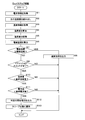
- the temperature difference between the ambient temperature of the wire and the temperature of the wire is calculated over time based on the current information indicating the current value flowing through the wire, and the calculated temperature Add the difference to the ambient temperature.
- the wire temperature is calculated.
- the calculated wire temperature is equal to or higher than the threshold temperature, for example, the current flowing through the wire is cut off by turning off a switch provided in the middle of the wire.
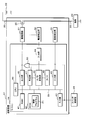
- Analog current information from the current detection unit 32 is input to the input unit 44.
- the input unit 44 outputs the input current information to the A / D conversion unit 48.
- the timer 49 periodically outputs to the A / D converter 48 a conversion instruction that instructs to convert analog current information into digital current information.
- the determination unit 47 determines whether or not the current value indicated by the current information input from the A / D conversion unit 48 is greater than or equal to the reference current value. Specifically, the determination unit 47 determines whether or not the digital current information, that is, the digital voltage value is greater than or equal to a reference value.
- the reference value is a digital voltage value output by the A / D converter 48 when the current of the reference current value flows through the electric wire 20. Further, the reference current value is sufficiently smaller than the aforementioned breaking current value.
- Rth is the wire thermal resistance (° C./W) of the wire 20
- Rw is the wire resistance ( ⁇ ) of the wire 20
- To is a predetermined temperature (° C.)
- Ro is a wire resistance ( ⁇ ) at the temperature To.
- ⁇ is the wire resistance temperature coefficient (/ ° C.) of the wire 20.
- ⁇ Tw, ⁇ Tp, Iw, and Ta are variables, and ⁇ t, ⁇ , Rth, Ro, ⁇ , and To are preset constants.
Landscapes
- Engineering & Computer Science (AREA)
- Mechanical Engineering (AREA)
- Emergency Protection Circuit Devices (AREA)
- Measurement Of Current Or Voltage (AREA)
- Charge And Discharge Circuits For Batteries Or The Like (AREA)
- Connection Of Batteries Or Terminals (AREA)
- Protection Of Static Devices (AREA)
- Pharmaceuticals Containing Other Organic And Inorganic Compounds (AREA)
- Electronic Switches (AREA)
Priority Applications (2)
| Application Number | Priority Date | Filing Date | Title |
|---|---|---|---|
| US15/552,909 US10326266B2 (en) | 2015-02-27 | 2016-02-23 | Interrupting device, interrupting method, and computer program |
| CN201680009083.8A CN107210601B (zh) | 2015-02-27 | 2016-02-23 | 切断装置、切断方法及存储有计算机程序的存储介质 |
Applications Claiming Priority (2)
| Application Number | Priority Date | Filing Date | Title |
|---|---|---|---|
| JP2015-038914 | 2015-02-27 | ||
| JP2015038914A JP6304072B2 (ja) | 2015-02-27 | 2015-02-27 | 遮断装置、遮断方法及びコンピュータプログラム |
Publications (1)
| Publication Number | Publication Date |
|---|---|
| WO2016136713A1 true WO2016136713A1 (ja) | 2016-09-01 |
Family
ID=56789243
Family Applications (1)
| Application Number | Title | Priority Date | Filing Date |
|---|---|---|---|
| PCT/JP2016/055188 Ceased WO2016136713A1 (ja) | 2015-02-27 | 2016-02-23 | 遮断装置、遮断方法及びコンピュータプログラム |
Country Status (4)
| Country | Link |
|---|---|
| US (1) | US10326266B2 (enExample) |
| JP (1) | JP6304072B2 (enExample) |
| CN (1) | CN107210601B (enExample) |
| WO (1) | WO2016136713A1 (enExample) |
Cited By (1)
| Publication number | Priority date | Publication date | Assignee | Title |
|---|---|---|---|---|
| US10404057B2 (en) * | 2015-01-15 | 2019-09-03 | Autonetworks Technologies, Ltd. | Power supply control apparatus |
Families Citing this family (7)
| Publication number | Priority date | Publication date | Assignee | Title |
|---|---|---|---|---|
| JP6531705B2 (ja) * | 2016-04-21 | 2019-06-19 | 株式会社デンソー | 回転電機の制御装置 |
| JP6882023B2 (ja) * | 2017-03-13 | 2021-06-02 | 矢崎総業株式会社 | 電線保護装置 |
| JP6901577B2 (ja) * | 2017-09-21 | 2021-07-14 | 新電元工業株式会社 | スイッチング素子制御回路及びパワーモジュール |
| TWI686028B (zh) * | 2018-04-23 | 2020-02-21 | 王國欽 | 電池保護架構 |
| JP7131211B2 (ja) | 2018-08-30 | 2022-09-06 | 株式会社オートネットワーク技術研究所 | 給電制御装置 |
| JP7670639B2 (ja) * | 2022-03-03 | 2025-04-30 | トヨタ自動車株式会社 | 車両 |
| DE102022132531A1 (de) | 2022-12-07 | 2024-06-13 | Cariad Se | Verfahren und Steuerschaltung zum Betreiben eines Schalterelements einer elektrischen Komponente, um deren Überhitzung durch elektrische Verlustwärme zu vermeiden, sowie elektrische Komponente mit der Steuerschaltung |
Citations (2)
| Publication number | Priority date | Publication date | Assignee | Title |
|---|---|---|---|---|
| JP2009232610A (ja) * | 2008-03-24 | 2009-10-08 | Yazaki Corp | 負荷回路の保護装置 |
| JP2014209824A (ja) * | 2013-04-16 | 2014-11-06 | 株式会社オートネットワーク技術研究所 | 遮断装置 |
Family Cites Families (6)
| Publication number | Priority date | Publication date | Assignee | Title |
|---|---|---|---|---|
| JP4762044B2 (ja) * | 2006-04-27 | 2011-08-31 | 矢崎総業株式会社 | 負荷回路の保護装置 |
| JP4624400B2 (ja) * | 2007-11-19 | 2011-02-02 | 株式会社オートネットワーク技術研究所 | 車両用の電線保護方法および電線保護装置 |
| JP2009303394A (ja) * | 2008-06-13 | 2009-12-24 | Yazaki Corp | 負荷回路の保護装置 |
| JP5381248B2 (ja) * | 2009-03-31 | 2014-01-08 | 株式会社オートネットワーク技術研究所 | 電力供給制御装置およびその制御方法 |
| JP5955502B2 (ja) * | 2010-12-09 | 2016-07-20 | 矢崎総業株式会社 | 負荷回路の断線検出装置 |
| JP6070496B2 (ja) | 2013-03-29 | 2017-02-01 | アイシン・エィ・ダブリュ株式会社 | ステータコイルの巻線形成装置及び巻線形成方法 |
-
2015
- 2015-02-27 JP JP2015038914A patent/JP6304072B2/ja not_active Expired - Fee Related
-
2016
- 2016-02-23 CN CN201680009083.8A patent/CN107210601B/zh not_active Expired - Fee Related
- 2016-02-23 WO PCT/JP2016/055188 patent/WO2016136713A1/ja not_active Ceased
- 2016-02-23 US US15/552,909 patent/US10326266B2/en active Active
Patent Citations (2)
| Publication number | Priority date | Publication date | Assignee | Title |
|---|---|---|---|---|
| JP2009232610A (ja) * | 2008-03-24 | 2009-10-08 | Yazaki Corp | 負荷回路の保護装置 |
| JP2014209824A (ja) * | 2013-04-16 | 2014-11-06 | 株式会社オートネットワーク技術研究所 | 遮断装置 |
Cited By (1)
| Publication number | Priority date | Publication date | Assignee | Title |
|---|---|---|---|---|
| US10404057B2 (en) * | 2015-01-15 | 2019-09-03 | Autonetworks Technologies, Ltd. | Power supply control apparatus |
Also Published As
| Publication number | Publication date |
|---|---|
| US10326266B2 (en) | 2019-06-18 |
| JP2016163403A (ja) | 2016-09-05 |
| CN107210601B (zh) | 2019-03-26 |
| CN107210601A (zh) | 2017-09-26 |
| JP6304072B2 (ja) | 2018-04-04 |
| US20180034259A1 (en) | 2018-02-01 |
Similar Documents
| Publication | Publication Date | Title |
|---|---|---|
| JP6304072B2 (ja) | 遮断装置、遮断方法及びコンピュータプログラム | |
| JP4762044B2 (ja) | 負荷回路の保護装置 | |
| JP2013229966A (ja) | 通電回路の保護装置 | |
| JP2016163403A5 (enExample) | ||
| JP2017077081A (ja) | 電流制御装置、電流制御方法及びコンピュータプログラム | |
| JP6176003B2 (ja) | 制御装置 | |
| WO2014162874A1 (ja) | 遮断装置 | |
| WO2013161362A1 (ja) | 通電回路の保護装置 | |
| CN107210600B (zh) | 供电控制装置 | |
| JP6003857B2 (ja) | 制御装置 | |
| JP2014209824A (ja) | 遮断装置 | |
| CN108370151B (zh) | 供电控制装置 | |
| CN108574269B (zh) | 电线保护装置 | |
| JP6107688B2 (ja) | 電線保護装置 | |
| JP2016163491A (ja) | 遮断装置、遮断方法及びコンピュータプログラム | |
| JP2014204514A (ja) | 電線保護装置及び電線保護方法 | |
| JP2010104138A (ja) | 直流モータの駆動装置 | |
| CN119134229A (zh) | 一种过流故障重启方法、装置、设备、介质及产品 |
Legal Events
| Date | Code | Title | Description |
|---|---|---|---|
| 121 | Ep: the epo has been informed by wipo that ep was designated in this application |
Ref document number: 16755457 Country of ref document: EP Kind code of ref document: A1 |
|
| NENP | Non-entry into the national phase |
Ref country code: DE |
|
| 122 | Ep: pct application non-entry in european phase |
Ref document number: 16755457 Country of ref document: EP Kind code of ref document: A1 |