WO2016132848A1 - 運転支援装置及び運転支援方法 - Google Patents
運転支援装置及び運転支援方法 Download PDFInfo
- Publication number
- WO2016132848A1 WO2016132848A1 PCT/JP2016/052506 JP2016052506W WO2016132848A1 WO 2016132848 A1 WO2016132848 A1 WO 2016132848A1 JP 2016052506 W JP2016052506 W JP 2016052506W WO 2016132848 A1 WO2016132848 A1 WO 2016132848A1
- Authority
- WO
- WIPO (PCT)
- Prior art keywords
- driver
- override
- driving
- vehicle
- switching
- Prior art date
Links
Images


Classifications
-
- B—PERFORMING OPERATIONS; TRANSPORTING
- B60—VEHICLES IN GENERAL
- B60W—CONJOINT CONTROL OF VEHICLE SUB-UNITS OF DIFFERENT TYPE OR DIFFERENT FUNCTION; CONTROL SYSTEMS SPECIALLY ADAPTED FOR HYBRID VEHICLES; ROAD VEHICLE DRIVE CONTROL SYSTEMS FOR PURPOSES NOT RELATED TO THE CONTROL OF A PARTICULAR SUB-UNIT
- B60W50/00—Details of control systems for road vehicle drive control not related to the control of a particular sub-unit, e.g. process diagnostic or vehicle driver interfaces
- B60W50/08—Interaction between the driver and the control system
- B60W50/12—Limiting control by the driver depending on vehicle state, e.g. interlocking means for the control input for preventing unsafe operation
-
- G—PHYSICS
- G08—SIGNALLING
- G08G—TRAFFIC CONTROL SYSTEMS
- G08G1/00—Traffic control systems for road vehicles
- G08G1/16—Anti-collision systems
Definitions
- This disclosure relates to a driving support technology for switching between automatic driving and manual driving.
- a technology for automatically driving a vehicle is known.
- a technology is known in which automatic driving is canceled and switched to manual driving by a driving operation (hereinafter referred to as “override”) by a driver during automatic driving.
- Patent Document 1 discloses a technique for switching from automatic driving to manual driving when an override such as a steering operation, a brake operation, or an accelerator operation by a driver is detected during automatic driving.
- This disclosure is intended to provide a driving support technology that suppresses switching from automatic driving to manual driving by an override that is not suitable for the situation in which the vehicle is placed.
- the driving support device of the present disclosure is mounted on a vehicle that performs automatic driving, and includes driving switching means for switching from automatic driving to manual driving, and override detection means for detecting an override by a driver, and the override detection means detects an override.
- the operation switching unit is a driving support device that switches from automatic operation to manual operation, and includes a driver state determination unit that sequentially determines whether or not the driver lacks concentration. Even if the override is detected by the override detection means, if the driver state determination means determines that the driver lacks concentration, the automatic operation is not switched to the manual operation.
- the driving support device of the present disclosure does not switch from the automatic driving to the manual driving if it is determined that the driver lacks concentration even if the driver override is detected. Therefore, even when the driver of the vehicle lacks concentration, even if an override that is not suitable for the situation in which the vehicle is placed is performed, it is not necessary to switch from automatic operation to manual operation. As a result, the driving support device according to the present disclosure can suppress switching from automatic driving to manual driving due to an override that is not suitable for the situation where the vehicle is placed.
- FIG. 1 is a block diagram illustrating an example of a schematic configuration of the driving support system according to the first embodiment.
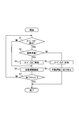
- FIG. 2 is a flowchart illustrating an example of a flow of override-related processing by the driving support apparatus according to the first embodiment.
- FIG. 3 is a block diagram illustrating an example of a schematic configuration of a driving support system according to a modification.
- FIG. 1 is a block diagram illustrating an example of a schematic configuration of a driving support system 100 to which the driving support device according to the present disclosure is applied.
- the driving support system 100 includes a driving support device 1, a surrounding environment recognition device 2, a vehicle behavior related sensor 3, and a brake switch 4.
- the driving support system 100 includes an accelerator switch 5, a steering torque sensor 6, a vehicle interior camera 7, and a vehicle control ECU 8, and is mounted on the vehicle.
- a vehicle equipped with the driving support system 100 is referred to as a host vehicle.
- the surrounding environment recognition device 2 includes a sensor such as a camera or a laser radar that images a predetermined range around the host vehicle.
- the surrounding environment recognition device 2 recognizes the surrounding environment of the host vehicle based on the detection information of the sensor. Examples of the surrounding environment to be recognized include a road shape around the host vehicle, a preceding vehicle located in front of the host vehicle, and an obstacle around the host vehicle.
- the surrounding environment recognition device 2 performs image recognition processing such as edge detection on the captured image of the camera. Thereby, the surrounding environment recognition apparatus 2 recognizes the lane of a road.
- the surrounding environment recognition device 2 calculates the lane width of the recognized lane, the radius of curvature of the lane, the offset amount of the host vehicle from the lane center, and the like. Thereby, the surrounding environment recognition apparatus 2 recognizes the road shape around the own vehicle.
- the surrounding environment recognition device 2 performs image recognition processing such as edge detection and template matching on the image captured by the camera. Thereby, the surrounding environment recognition device 2 specifies the size of the preceding vehicle, the size of the obstacle around the host vehicle, and the relative position with the host vehicle. And the surrounding environment recognition apparatus 2 specifies the moving speed and moving direction of a preceding vehicle or an obstruction based on the temporal change rate of the relative position of the own vehicle with respect to the specified preceding vehicle or an obstruction. In addition, when the surrounding environment recognition device 2 uses a laser radar, a millimeter wave radar, or a sonar, the surrounding environment recognition device 2 detects a preceding vehicle or an obstacle based on the received intensity of the reflected wave generated by reflecting the transmitted exploration wave on the object. What is necessary is just to detect.
- the surrounding environment recognition device 2 When the exploration wave can be scanned, the surrounding environment recognition device 2 identifies the direction of the preceding vehicle and the obstacle with respect to the own vehicle from the transmission direction of the exploration wave corresponding to the reflected wave. And the surrounding environment recognition apparatus 2 determines the distance from the own vehicle to a preceding vehicle and an obstruction based on the specified direction and the time from when the exploration wave is transmitted until the reflected wave is received. Further, in the case of a radar, the surrounding environment recognition device 2 may be configured to determine the relative position of a preceding vehicle or an obstacle with respect to the own vehicle using an amplitude comparison monopulse type radar or a phase comparison monopulse type radar.
- the relative speed of the preceding vehicle and the obstacle with respect to the host vehicle may be determined by a predetermined method based on the Doppler shift between the exploration wave and the reflected wave. Moreover, it is good also as a structure determined based on the temporal change rate of the relative position with respect to the own vehicle of the preceding vehicle and obstacle which are determined sequentially.
- the vehicle behavior related sensor 3 detects information related to the behavior of the host vehicle (hereinafter referred to as “vehicle behavior information”).
- vehicle behavior information includes a vehicle speed sensor, an acceleration sensor, and a gyro sensor.
- the vehicle speed sensor detects the vehicle speed of the host vehicle.
- the acceleration sensor detects the acceleration of the host vehicle.
- the gyro sensor detects the angular velocity of the host vehicle.
- Other vehicle behavior related sensors 3 include a receiver that receives information capable of calculating the position of the vehicle from a positioning satellite of a positioning satellite system.
- the brake switch 4 is a switch that is turned on when the brake pedal of the host vehicle is depressed, and turned off when the brake pedal is not depressed.
- the brake switch 4 outputs a signal corresponding to on / off.
- the accelerator switch 5 is a switch that is turned on when the accelerator pedal of the host vehicle is depressed, and turned off when the accelerator pedal is not depressed.
- the accelerator switch 5 outputs a signal corresponding to on / off.
- the steering torque sensor 6 detects the steering torque applied to the steering wheel of the host vehicle by the driving operation of the driver.
- the vehicle interior camera 7 corresponds to a biological information sensor, and is a sensor that senses a driver to determine whether or not the driver who is in the vehicle is in a state of lacking concentration (a state in which concentration is reduced). Function as.
- the vehicle interior camera 7 sequentially captures a predetermined range (predetermined imaging region) including the face of the driver who is in the host vehicle at predetermined time intervals (for example, at 100 msec intervals).
- the vehicle interior camera 7 may be installed at a position where a predetermined range including the driver's face, such as the upper surface of the steering column cover, can be imaged.
- the vehicle interior camera 7 may be an optical camera or an infrared camera that can capture images even in an environment with little visible light.
- the vehicle control ECU 8 is an electronic control device that performs speed control (acceleration / deceleration control) and steering control of the host vehicle.
- Examples of the vehicle control ECU 8 include a steering ECU, an engine ECU, and a brake ECU.
- the steering ECU performs steering control of the host vehicle.
- the engine ECU and the brake ECU perform speed control of the host vehicle including acceleration / deceleration.
- the driving support device 1 includes a CPU, a memory (ROM, RAM, etc.), and an I / O, which are connected via a bus.
- the CPU executes a program stored in the memory.
- the driving assistance apparatus 1 the process for implement
- the driving support device 1 is provided with a driving support function for switching between automatic driving and manual driving.
- an instruction signal is output to the vehicle control ECU 8 to instruct execution of automatic driving.
- the driving support device 1 switches from automatic driving to manual driving based on the detection result of the driving operation (hereinafter referred to as “override”) by the driver during automatic driving. Details of these driving support devices 1 will be described later.
- the driving support apparatus 1 may be configured to realize part or all of the functions provided by the execution of the program by one or a plurality of hardware (for example, ICs).
- the driving support apparatus 1 includes an automatic driving control unit 11, an override detection unit 12, a driver state determination unit 13, an availability determination unit 14, and a driving switching unit 15.
- the automatic driving control unit 11 Based on the detection information of the surrounding environment of the host vehicle recognized by the surrounding environment recognition device 2 and the vehicle behavior information of the host vehicle detected by the vehicle behavior related sensor 3, the automatic driving control unit 11 performs the target travel at the time of automatic driving. Determine the course and target speed. Then, the automatic operation control unit 11 outputs an instruction signal for automatic operation to the vehicle control ECU 8 based on the determined target travel route and target travel speed. As a result, the vehicle control ECU 8 changes the vehicle steering angle, the brake pressure, the intake air amount, the gear ratio, etc. according to the input instruction signal, and automatically operates so that the host vehicle travels at the target travel path and the target travel speed. Control. As an example of automatic driving, there are automatic driving that keeps the traveling lane of the own vehicle on an expressway, automatic driving that retreats to the road shoulder when the own vehicle is abnormal, automatic driving that follows the preceding vehicle, etc. is there.
- the override detection unit 12 detects an override during automatic operation. That is, the override detection unit 12 functions as an override detection unit that detects an override by the driver.
- the override detection unit 12 according to the present embodiment detects the following driving operation by the driver as an override. For example, the override detection unit 12 detects a brake operation by the driver as an override when the brake switch 4 is on.
- the override detection unit 12 detects an accelerator operation by the driver as an override when the accelerator switch 5 is on.
- the override detection unit 12 detects a steering operation by the driver as an override based on the steering torque detected by the steering torque sensor 6.
- the detection of the brake operation and the accelerator operation by the driver is not limited to the detection method based on the on / off state of the brake switch 4 and the accelerator switch 5.
- the brake operation by the driver may be detected based on a signal from a brake stroke sensor that detects the depression amount of the brake pedal.
- the accelerator operation by the driver may be detected based on a signal from an accelerator stroke sensor that detects the amount of depression of the accelerator pedal.
- the driver state determination unit 13 sequentially determines at predetermined time intervals whether or not the driver who is in the vehicle is in a state where the driver lacks concentration (a state where concentration is reduced). That is, the driver state determination unit 13 functions as a driver state determination unit that sequentially determines whether or not the driver lacks concentration.
- the driver state determination unit 13 is based on a captured image including the driver's face of the host vehicle captured by the in-vehicle camera 7 (hereinafter referred to as “face image”). It is sequentially determined whether or not.
- face image a captured image including the driver's face of the host vehicle captured by the in-vehicle camera 7
- the driver state determination unit 13 detects the pupil and corneal reflection of the driver through image recognition processing of the face image captured by the vehicle interior camera 7.
- the driver state determination unit 13 detects the direction of the driver's line of sight based on the positional relationship between the detected pupil and corneal reflection.
- the driver state determination unit 13 determines that the driver is looking aside when the direction of the detected line of sight deviates more than a predetermined angle from the front of the traveling direction of the host vehicle.
- the predetermined angle mentioned here is a value that can be determined that the driver is looking aside and can be arbitrarily set.
- the driver state determination unit 13 detects the direction of the driver's face, not the direction of the driver's line of sight, by image recognition processing of the face image captured by the vehicle interior camera 7.
- the driver state determination unit 13 may determine that the driver is looking aside when the detected face orientation deviates more than a predetermined angle from the front in the traveling direction of the host vehicle. Good.
- the driver state determination unit 13 performs predetermined image processing on the face image captured by the vehicle interior camera 7, and based on the image processing result (face image after image processing), the degree of eye opening of the driver's eyes (For example, the ratio of the period when the eyes are closed) is detected.
- the driver state determination unit 13 may determine that the driver is in a sleepy state based on the detected degree of eye opening.
- the degree of eye opening (threshold for determination) determined to be a sloppy state may be a value that can determine the drowsiness of the driver, and can be arbitrarily set.
- the availability determination unit 14 determines the validity (valid or invalid) of the override detected during the automatic operation.
- the override detection unit 12 detects an override
- the propriety determination unit 14 determines that the detected override is invalid if the driver state determination unit 13 determines that the state is a random state.
- the override detection unit 12 detects an override
- the propriety determination unit 14 determines that the detected override is valid if the driver state determination unit 13 does not determine that it is in a random state. That is, when the override is detected, the availability determination unit 14 determines whether the override is valid (valid or invalid) depending on whether or not the driver has determined that the driver is in a loose state (a state that lacks concentration). It functions as an availability determination means.
- the operation switching unit 15 switches between automatic operation and manual operation. That is, the operation switching unit 15 functions as an operation switching unit that switches from automatic operation to manual operation.
- the driving switching unit 15 receives a switching instruction between automatic driving and manual driving from a driver via, for example, an operation input unit provided on the steering of the host vehicle.
- the driving switching unit 15 outputs an instruction signal for switching from manual driving to automatic driving to the vehicle control ECU 8 when an operation input for instructing automatic driving is received from the driver.
- the driving switching unit 15 outputs an instruction signal for switching from automatic driving to manual driving to the vehicle control ECU 8 when receiving an operation input for instructing manual driving from the driver.
- operation switching part 15 outputs the instruction
- the override related process is a process related to an override during automatic driving of the host vehicle.
- FIG. 2 for example, when the automatic driving control unit 11 starts automatic driving of the host vehicle, an example of processing in the case of starting execution of the override related processing is shown.
- the driving support device 1 detects the override by the driver during automatic driving by the override detection unit 12 (step S1). As a result, when the override detection unit 12 detects an override (step S1: YES), the driving support device 1 proceeds to the process of step S2. On the other hand, when the override detection unit 12 has not detected an override (step S1: NO), the driving support device 1 proceeds to the process of step S4.
- step S1 the driving assistance device 1 acquires the determination result of the driver's indecent state (a state lacking concentration) that is sequentially determined by the driver state determination unit 13 (step S2). ).
- step S2 the driver state determination unit 13 determines that the driver's state is a loose state
- step S3 the driving support device 1 proceeds to the process of step S3.
- step S2 NO
- step S3 When the driving support device 1 makes an affirmative determination in the process of step S2, the availability determination unit 14 determines that the override detected by the override detection unit 12 is invalid (step S3). And the driving assistance apparatus 1 continues an automatic driving
- the driving support device 1 determines whether it is the end timing of the override related process after the process of step S4 (step S7). As a result, when it is determined that it is the end timing (step S7: YES), the driving support device 1 ends the override related process. On the other hand, when it determines with the driving assistance apparatus 1 not being the completion
- the end timing of the override-related processing include when the ignition power of the host vehicle is turned off or when an operation input for instructing manual driving is received from the driver via the operation input unit. .
- the driver state determination unit 13 determines whether or not the driver's state is loose.
- the availability determination unit 14 does not determine the validity (valid or invalid) of the detected override.
- the propriety determination unit 14 is based on the determination result of the driver's random state that is sequentially determined by the driver state determination unit 13. Determines the validity of the detected override. In other words, in this embodiment, every time an override is detected, it is not determined whether or not the driver is in a random state.
- the driving assistance apparatus 1 when an override is detected, the latest determination result as to whether or not the driver is in a random state is obtained. Therefore, in the driving assistance apparatus 1 according to the present embodiment, it is possible to reduce a delay in timing from when the override detection unit 12 detects the override until the automatic driving is switched to the manual driving.
- the driver state determination unit 13 sequentially determines the presence or absence of a sloppy state such as a driver's side-view or doze.
- the driver state determination unit 13 determines that the driver state is in a loose state. If it is, switch from automatic operation to manual operation. More specifically, in the driving support device 1, the availability determination unit 14 determines that the detected override is invalid, and does not cause the driving switching unit 15 to switch from automatic driving to manual driving. Thereby, in the driving assistance apparatus 1 which concerns on this embodiment, it becomes possible to suppress the switch from the automatic driving
- the driver state determination unit 13 determines whether or not the driver's state is indiscriminate.
- the method for determining the driver's mood state is not limited to this.
- a configuration in which it is determined whether or not the driver is in a sloppy state using a detection result of a biological information sensor other than the vehicle interior camera 7 hereinafter, this configuration is referred to as “variation 1”. It is good also as.
- the driving support system 200 according to the first modification includes a driving support device 1a, a surrounding environment recognition device 2, a vehicle behavior related sensor 3, and a brake switch 4.
- the driving support system 200 includes an accelerator switch 5, a steering torque sensor 6, a vehicle interior camera 7, a vehicle control ECU 8, and a heart rate sensor 9.
- the driving support system 200 according to the first modification includes the driving support system 200 according to the first embodiment, except that the driving support system 200 includes the heart rate sensor 9 and the driving support apparatus 1a instead of the driving support apparatus 1. 100.
- the heart rate sensor 9 measures the heart rate of the driver.
- the modification 1 shows an example in which the heart rate sensor 9 is used in addition to the in-vehicle camera 7 as a biological information sensor for determining the driver's mood state
- the configuration of the biological information sensor to be used is not limited to this.
- a pulse sensor that measures a pulse rate, a respiratory sensor that measures a respiration rate, or the like may be used.
- the driving support apparatus 1 a according to the first modification includes an automatic driving control unit 11, an override detection unit 12, a driver state determination unit 13 a, an availability determination unit 14, and a driving switching unit 15.
- the driving support device 1a according to the first modification is the same as the driving support device 1 according to the first embodiment, except that a driver state determination unit 13a is provided instead of the driver state determination unit 13.
- the driver state determination unit 13a according to Modification 1 determines whether or not the driver state is a loose state based on the driver's heart rate sequentially detected by the heart rate sensor 9 in addition to the driver's face image captured by the vehicle interior camera 7. Determine whether. Except for this point, the driver state determination unit 13a according to the first modification is the same as the driver state determination unit 13 according to the first embodiment. For example, the driver state determination unit 13a according to the first modification determines whether or not the driver state is an ambiguous state as follows. Based on the driver's face image captured by the vehicle interior camera 7, the driver state determination unit 13a determines a casual state such as an aside look. In addition, the driver state determination unit 13a determines a casual state such as falling asleep based on the heart rate of the driver measured by the heart rate sensor 9.
- the driver's casual state is determined based on the detection results of a plurality of types of biological information sensors.
- the driving assistance device 1a according to the first modification it is possible to determine the driver's casual state that cannot be determined by only one type of biological information sensor.
- Modification 2 Further, as another modified example (modified example 2), it is determined whether or not the driver is in a loose state using the detection result of the biological information sensor other than the vehicle interior camera 7 without using the vehicle interior camera 7. It is good also as a structure which the part 13 determines. More specifically, in the second modification, for example, the direction of the driver's face is estimated based on the detection result of an acceleration sensor or a gyro sensor provided in an instrument attached to the driver's face. And in the modification 2, it is determined based on an estimation result whether a driver is in an abusive state.
- Modification 3 As another modified example (modified example 3), based on the determination result of the consistency between the override detected by the override detection unit 12 and the state of the driver detected by the biological information sensor, the driver state determination unit 13, 13a is good also as a structure which determines the driver's vague state of the own vehicle.
- the override detection unit 12 detects a steering operation of the host vehicle by the driver as an override. Therefore, in the third modification, the driver's line-of-sight direction or face direction recognized by the image recognition processing of the face image captured by the vehicle interior camera 7 does not match the steering operation direction detected by the override detection unit 12.
- the driver state determination units 13 and 13a may determine that the state of the driver is a random state.
- Modification 4 As another modification (Modification 4), after the override detection unit 12 detects an override, the driver state determination units 13 and 13a determine the driver's casual state. And in the modification 4, it is good also as a structure in which the determination part 14 determines the validity (valid or invalid) of the detected override based on the determination result of a casual state.
- driving support devices 1 and 1a of the present disclosure are not limited to the above-described embodiment, and various modifications can be made within the technical scope of the present disclosure. Further, the driving assistance devices 1 and 1a of the present disclosure also include embodiments obtained by appropriately combining the technical means disclosed in the above-described embodiments within the technical scope of the present disclosure.
Abstract
運転支援装置1は、自動運転から手動運転に切り替える切替部15と、ドライバによるオーバーライドを検出する検出部12と、ドライバが漫然状態か否かを逐次判定する判定部13とを備える。切替部15は、検出部12が、オーバーライドを検出した場合に、判定部13が、漫然状態でないと判定していた場合には、自動運転から手動運転へ切り替える。一方、切替部15は、検出部12が、オーバーライドを検出した場合であっても、判定部13が、漫然状態であると判定していた場合には、自動運転から手動運転へ切り替えない。
Description
本開示は、自動運転と手動運転とを切り替える運転支援技術に関する。
従来では、車両を自動運転する技術が知られている。また、従来では、自動運転中のドライバによる運転操作(以下「オーバーライド」という)によって、自動運転を解除し、手動運転に切り替える技術が知られている。
例えば、特許文献1には、自動運転時にドライバによるステアリング操作、ブレーキ操作、アクセル操作等のオーバーライドを検出した場合、自動運転から手動運転に切り替える技術が開示されている。
しかしながら、特許文献1の技術では、脇見等の集中力を欠いたドライバの運転状態(集中力が低下したドライバの運転状態)により、車両のおかれた状況に適していないオーバーライドが行われた場合でも、自動運転から手動運転に切り替えてしまうという問題点がある。
本開示は、車両のおかれた状況に適していないオーバーライドによる自動運転から手動運転への切り替えを抑制する運転支援技術を提供することを目的とする。
本開示の運転支援装置は、自動運転を行う車両に搭載され、自動運転から手動運転に切り替える運転切替手段と、ドライバによるオーバーライドを検出するオーバーライド検出手段とを備え、オーバーライド検出手段がオーバーライドを検出した場合に、運転切替手段が自動運転から手動運転に切り替える運転支援装置であって、ドライバが集中力を欠いた状態であるか否かを逐次判定するドライバ状態判定手段を備え、運転切替手段は、オーバーライド検出手段でオーバーライドを検出した場合であっても、ドライバ状態判定手段でドライバが集中力を欠いた状態であると判定している場合には、自動運転から手動運転へ切り替えない。
ドライバが集中力を欠いた状態は、車両のおかれた状況に適していない運転操作を行いやすい状況にあると言える。これに対して、本開示の運転支援装置は、ドライバによるオーバーライドを検出しても、ドライバが集中力を欠いた状態であると判定している場合には、自動運転から手動運転へ切り替えない。よって、車両のドライバが集中力を欠いた状態のときに、車両のおかれた状況に適していないオーバーライドを行ってしまった場合でも、自動運転から手動運転へ切り替えずに済む。その結果、本開示の運転支援装置は、車両のおかれた状況に適していないオーバーライドによる自動運転から手動運転への切り替えを抑制することが可能になる。
(実施形態1)
<運転支援システムの概略構成>
以下、本開示の運転支援装置における実施形態について図面を用いて説明する。図1は、本開示の運転支援装置が適用された運転支援システム100の概略構成の一例を示すブロック図である。図1に示すように、本実施形態に係る運転支援システム100は、運転支援装置1、周辺環境認識装置2、車両挙動関連センサ3、ブレーキスイッチ4を備えている。また、運転支援システム100は、アクセルスイッチ5、操舵トルクセンサ6、車室内カメラ7、及び車両制御ECU8を備え、車両に搭載される。以降では、運転支援システム100を搭載した車両を自車両という。
<運転支援システムの概略構成>
以下、本開示の運転支援装置における実施形態について図面を用いて説明する。図1は、本開示の運転支援装置が適用された運転支援システム100の概略構成の一例を示すブロック図である。図1に示すように、本実施形態に係る運転支援システム100は、運転支援装置1、周辺環境認識装置2、車両挙動関連センサ3、ブレーキスイッチ4を備えている。また、運転支援システム100は、アクセルスイッチ5、操舵トルクセンサ6、車室内カメラ7、及び車両制御ECU8を備え、車両に搭載される。以降では、運転支援システム100を搭載した車両を自車両という。
周辺環境認識装置2は、自車両周辺の所定範囲を撮像するカメラやレーザレーダ等のセンサを備える。周辺環境認識装置2は、センサの検出情報に基づいて、自車両の周辺環境を認識する。認識対象となる周辺環境の一例としては、自車両周辺の道路形状、自車両前方に位置する先行車両、及び自車両周辺の障害物等がある。
例えば、周辺環境認識装置2は、カメラの撮像画像に対してエッジ検出等の画像認識処理を行う。これにより、周辺環境認識装置2は、道路の車線を認識する。周辺環境認識装置2は、認識した車線の車線幅、車線の曲率半径、車線中心からの自車両のオフセット量等を算出する。これにより、周辺環境認識装置2は、自車両周辺の道路形状を認識する。
周辺環境認識装置2は、カメラの撮像画像に対してエッジ検出やテンプレートマッチング等の画像認識処理を行う。これにより、周辺環境認識装置2は、先行車両の大きさや自車両周辺の障害物の大きさ、自車両との相対位置を特定する。そして、周辺環境認識装置2は、特定した先行車両や障害物に対する自車両の相対位置の時間的な変化率に基づいて、先行車両や障害物の移動速度や移動方向を特定する。また、周辺環境認識装置2は、レーザレーダ、ミリ波レーダ、ソナーを用いる場合には、送信した探査波が物体に反射されて生じた反射波の受信強度に基づいて、先行車両や障害物を検出すればよい。周辺環境認識装置2は、探査波を走査できる場合には、反射波に対応する探査波の送信方向から、自車両に対する先行車両や障害物の方位を特定する。そして、周辺環境認識装置2は、特定した方位と、探査波を送信してから反射波を受信するまでの時間とに基づいて、自車両から先行車両や障害物までの距離を決定する。また、周辺環境認識装置2は、レーダの場合には、振幅比較モノパルス方式や位相比較モノパルス方式のレーダを用いて、自車両に対する先行車両や障害物の相対位置を決定する構成としてもよい。自車両に対する先行車両や障害物の相対速度については、探査波と反射波とのドップラーシフトに基づいて、所定の方法によって決定する構成としてもよい。また、逐次決定される先行車両や障害物の自車両に対する相対位置の時間的な変化率に基づき決定する構成としてもよい。
車両挙動関連センサ3は、自車両の挙動に関連する情報(以下「車両挙動情報」という)を検出する。車両挙動関連センサ3の一例としては、車速センサ、加速度センサ、及びジャイロセンサ等がある。車速センサは、自車両の車速を検出する。加速度センサは、自車両の加速度を検出する。ジャイロセンサは、自車両の角速度を検出する。その他の車両挙動関連センサ3としては、測位衛星システムの測位衛星から自車両位置を演算可能な情報を受信する受信機等がある。
ブレーキスイッチ4は、自車両のブレーキペダルの踏み込み操作がなされているときにオンとなり、一方、ブレーキペダルの踏み込み操作がなされていないときにオフとなるスイッチである。ブレーキスイッチ4は、オンオフに応じた信号を出力する。アクセルスイッチ5は、自車両のアクセルペダルの踏み込み操作がなされているときにオンとなり、一方、アクセルペダルの踏み込み操作がなされていないときにオフとなるスイッチである。アクセルスイッチ5は、オンオフに応じた信号を出力する。操舵トルクセンサ6は、ドライバの運転操作によって、自車両のステアリングホイールに印加された操舵トルクを検出する。
車室内カメラ7は、生体情報センサに相当し、自車両に乗車中のドライバが集中力を欠いた状態(集中力が低下した状態)であるか否かを判定するためにドライバをセンシングするセンサとして機能する。車室内カメラ7は、自車両に乗車中のドライバの顔を含む所定の範囲(所定の撮像領域)を、所定の時間間隔で(例えば100msec間隔で)逐次撮像する。車室内カメラ7は、例えば、ステアリングコラムカバーの上面部等、ドライバの顔を含む所定の範囲を撮像可能な位置に設置すればよい。車室内カメラ7は、光学式カメラであってもよいし、可視光の少ない環境下においても撮像可能な赤外線カメラであってもよい。
車両制御ECU8は、自車両の速度制御(加減速度制御)や操舵制御を行う電子制御装置である。車両制御ECU8の一例としては、操舵ECU、エンジンECU、及びブレーキECU等がある。操舵ECUは、自車両の操舵制御を行う。エンジンECU及びブレーキECUは、加減速度を含む自車両の速度制御を行う。
運転支援装置1は、CPU、メモリ(ROMやRAM等)、及びI/Oを備え、これらがバスを介して接続されている。運転支援装置1では、メモリに記憶されたプログラムをCPUが実行する。これにより、運転支援装置1では、各種運転支援機能を実現するための処理が実行される。その結果、運転支援装置1では、自動運転と手動運転とを切り替える運転支援機能が提供される。このとき、手動運転から自動運転に切り替える場合には、車両制御ECU8に指示信号を出力し、自動運転の実行を指示する。また、運転支援装置1では、自動運転中のドライバによる運転操作(以下「オーバーライド」という)の検出結果に基づいて、自動運転から手動運転への切り替えを行う。これらの運転支援装置1の詳細については後述する。なお、本開示の運転支援装置1では、上記プログラムの実行により提供される機能の一部又は全部を、1又は複数のハードウェア(例えばIC等)により実現する構成としてもよい。
<運転支援装置1の概略構成>
図1に示すように、本実施形態に係る運転支援装置1は、自動運転制御部11、オーバーライド検出部12、ドライバ状態判定部13、可否判定部14、及び運転切替部15を備えている。
図1に示すように、本実施形態に係る運転支援装置1は、自動運転制御部11、オーバーライド検出部12、ドライバ状態判定部13、可否判定部14、及び運転切替部15を備えている。
自動運転制御部11は、周辺環境認識装置2が認識した自車両の周辺環境の検出情報と、車両挙動関連センサ3が検出した自車両の車両挙動情報とに基づいて、自動運転時の目標走行進路及び目標走行速度を決定する。そして、自動運転制御部11は、決定した目標走行進路や目標走行速度に基づいて、自動運転の指示信号を車両制御ECU8に出力する。その結果、車両制御ECU8では、入力された指示信号に従って、車両の操舵角、ブレーキ圧、吸気量、変速比等を変化させ、目標走行進路や目標走行速度で自車両が走行するように自動運転の制御を行う。自動運転の一例としては、高速道路等で自車両の走行車線を維持して走行する自動運転、自車両の異常時に路肩に退避する自動運転、及び先行車両に追従して走行する自動運転等がある。
オーバーライド検出部12は、自動運転中におけるオーバーライドを検出する。つまり、オーバーライド検出部12は、ドライバによるオーバーライドを検出するオーバーライド検出手段として機能する。本実施形態に係るオーバーライド検出部12では、ドライバによる次のような運転操作をオーバーライドとして検出する。例えば、オーバーライド検出部12は、ブレーキスイッチ4がオンの場合に、ドライバによるブレーキ操作をオーバーライドとして検出する。また、オーバーライド検出部12は、アクセルスイッチ5がオンの場合に、ドライバによるアクセル操作をオーバーライドとして検出する。また、オーバーライド検出部12は、操舵トルクセンサ6が検出した操舵トルクに基づいて、ドライバによるステアリング操作をオーバーライドとして検出する。なお、ドライバによるブレーキ操作及びアクセル操作の検出は、ブレーキスイッチ4及びアクセルスイッチ5のオンオフ状態に基づく検出方法に限らない。例えば、ドライバによるブレーキ操作は、ブレーキペダルの踏み込み量を検出するブレーキストロークセンサの信号に基づいて検出してもよい。また、ドライバによるアクセル操作は、アクセルペダルの踏み込み量を検出するアクセルストロークセンサの信号に基づいて検出してもよい。
ドライバ状態判定部13は、自車両に乗車中のドライバが集中力を欠いた状態(集中力が低下した状態)であるか否かを、所定の時間間隔で逐次判定する。つまり、ドライバ状態判定部13は、ドライバが集中力を欠いた状態であるか否かを逐次判定するドライバ状態判定手段として機能する。ドライバ状態判定部13は、車室内カメラ7が撮像した自車両のドライバの顔を含む撮像画像(以下「顔画像」という)に基づいて、ドライバが集中力を欠いた状態(以下便宜上「漫然状態」という)であるか否かを逐次判定する。ドライバ状態判定部13は、例えば、自動運転が開始する前から逐次判定を行う。
例えば、ドライバ状態判定部13は、車室内カメラ7が撮像した顔画像の画像認識処理によって、ドライバの瞳孔及び角膜反射を検出する。そして、ドライバ状態判定部13は、検出した瞳孔と角膜反射との位置関係に基づいて、ドライバの視線の方向を検出する。その結果、ドライバ状態判定部13は、検出した視線の方向が自車両の進行方向前方から所定の角度以上外れている場合に、ドライバが脇見をしている漫然状態であると判定する。ここで言う所定の角度とは、ドライバが脇見をしていると判定可能な値であり、任意に設定可能である。
なお、ドライバの漫然状態の判定方法は、この限りでない。例えば、ドライバ状態判定部13は、車室内カメラ7が撮像した顔画像の画像認識処理によって、ドライバの視線の方向でなく、ドライバの顔の向きを検出する。そして、ドライバ状態判定部13は、検出した顔の向きが自車両の進行方向前方から所定の角度以上外れている場合に、ドライバが脇見をしている漫然状態であると判定するようにしてもよい。また、ドライバ状態判定部13は、車室内カメラ7が撮像した顔画像に対して、所定の画像処理を行い、画像処理結果(画像処理後の顔画像)に基づいて、ドライバの目の開眼度合い(例えば目を閉じている期間の割合)を検出する。そして、ドライバ状態判定部13は、検出した開眼度合いに基づいて、ドライバが居眠りをしている漫然状態であると判定するようにしてもよい。このとき、漫然状態と判定する開眼度合い(判定用の閾値)は、ドライバの眠気を判定可能な値とすればよく、任意に設定可能である。
可否判定部14は、自動運転中に検出されたオーバーライドの有効性(有効か無効か)を判定する。可否判定部14は、オーバーライド検出部12がオーバーライドを検出したときに、ドライバ状態判定部13が漫然状態と判定していた場合には、検出したオーバーライドを無効と判定する。一方、可否判定部14は、オーバーライド検出部12がオーバーライドを検出したときに、ドライバ状態判定部13が漫然状態と判定していなかった場合には、検出したオーバーライドを有効と判定する。つまり、可否判定部14は、オーバーライドを検出した場合に、ドライバが漫然状態(集中力を欠いた状態である)と判定しているか否かに応じて、オーバーライドの有効性(有効か無効か)を判定する可否判定手段として機能する。
運転切替部15は、自動運転と手動運転との切り替えを行う。つまり、運転切替部15は、自動運転から手動運転に切り替える運転切替手段として機能する。運転切替部15は、例えば、自車両のステアリング等に設けられた操作入力部を介して、ドライバから、自動運転と手動運転との切り替え指示を受け付ける。運転切替部15は、ドライバから自動運転を指示する旨の操作入力を受け付けた場合に、手動運転から自動運転に切り替える指示信号を車両制御ECU8に出力する。一方、運転切替部15は、ドライバから手動運転を指示する旨の操作入力を受け付けた場合に、自動運転から手動運転に切り替える指示信号を車両制御ECU8に出力する。また、運転切替部15は、可否判定部14が、自動運転中に検出されたオーバーライドを有効と判定した場合に、自動運転から手動運転へ切り替える指示信号を車両制御ECU8に出力する。
<オーバーライド関連処理>
続いて、本実施形態に係る運転支援装置1によるオーバーライド関連処理の流れの一例について、図2を用いて説明を行う。オーバーライド関連処理とは、自車両の自動運転中におけるオーバーライドに関連した処理である。図2のフローチャートには、例えば、自動運転制御部11によって自車両の自動運転が開始されたときに、オーバーライド関連処理の実行を開始する場合の処理例が示されている。
続いて、本実施形態に係る運転支援装置1によるオーバーライド関連処理の流れの一例について、図2を用いて説明を行う。オーバーライド関連処理とは、自車両の自動運転中におけるオーバーライドに関連した処理である。図2のフローチャートには、例えば、自動運転制御部11によって自車両の自動運転が開始されたときに、オーバーライド関連処理の実行を開始する場合の処理例が示されている。
運転支援装置1は、オーバーライド検出部12により、自動運転中のドライバによるオーバーライドを検出する(ステップS1)。その結果、運転支援装置1は、オーバーライド検出部12がオーバーライドを検出した場合(ステップS1:YES)、ステップS2の処理に移る。一方、運転支援装置1は、オーバーライド検出部12がオーバーライドを検出していない場合(ステップS1:NO)、ステップS4の処理に移る。
運転支援装置1は、ステップS1の処理で肯定判定されると、ドライバ状態判定部13により逐次判定されているドライバの漫然状態(集中力を欠いている状態)の判定結果を取得する(ステップS2)。その結果、運転支援装置1は、ドライバ状態判定部13がドライバの状態を漫然状態と判定している場合(ステップS2:YES)、ステップS3の処理に移る。一方、運転支援装置1は、ドライバ状態判定部13がドライバの状態を漫然状態と判定していない場合(ステップS2:NO)、ステップS5の処理に移る。
運転支援装置1は、ステップS2の処理で肯定判定されると、可否判定部14が、オーバーライド検出部12で検出されたオーバーライドを無効と判定する(ステップS3)。そして、運転支援装置1は、自動運転を継続し(ステップS4)、ステップS7の処理に移る。また、運転支援装置1は、ステップS2の処理で否定判定されると、可否判定部14が、オーバーライド検出部12で検出されたオーバーライドを有効と判定する(ステップS5)。そして、運転支援装置1は、運転切替部15が自動運転から手動運転への切り替えを行い(ステップS6)、オーバーライド関連処理を終了する。
運転支援装置1は、ステップS4の処理後に、オーバーライド関連処理の終了タイミングか否かを判定する(ステップS7)。その結果、運転支援装置1は、終了タイミングであると判定した場合(ステップS7:YES)、オーバーライド関連処理を終了する。一方、運転支援装置1は、オーバーライド関連処理の終了タイミングではないと判定した場合(ステップS7:NO)、ステップS1の処理に戻り、以降の処理を繰り返す。なお、オーバーライド関連処理の終了タイミングの一例としては、自車両のイグニッション電源がオフになったときや、操作入力部を介してドライバから手動運転を指示する旨の操作入力を受け付けたとき等がある。
本実施形態に係る運転支援装置1では、オーバーライド検出部12が、オーバーライドを検出した後に、ドライバ状態判定部13が、ドライバの状態が漫然状態か否かの判定を行う。そして、可否判定部14が、検出されたオーバーライドの有効性(有効か無効か)を判定するのではない。本実施形態に係る運転支援装置1では、オーバーライド検出部12が、オーバーライドを検出した場合に、ドライバ状態判定部13により逐次判定されているドライバの漫然状態の判定結果に基づいて、可否判定部14が、検出されたオーバーライドの有効性を判定する。つまり、本実施形態では、オーバーライドを検出する度に、その都度、ドライバの状態が漫然状態か否かの判定を行わない。本実施形態では、オーバーライドを検出したときには、ドライバの状態が漫然状態か否かの最新の判定結果が得られるようになっている。よって、本実施形態に係る運転支援装置1では、オーバーライド検出部12がオーバーライドを検出してから、自動運転を手動運転に切り替えるまでのタイミングの遅れを小さくすることができる。
<実施形態1のまとめ>
ドライバが脇見や居眠りといった漫然状態にある場合には、運転操作をするつもりがないのに運転操作を行ってしまったり、あわてて誤った運転操作を行ってしまったりすることが考えられる。そこで、本実施形態に係る運転支援装置1では、ドライバ状態判定部13がドライバの脇見や居眠りといった漫然状態の有無を逐次判定している。
ドライバが脇見や居眠りといった漫然状態にある場合には、運転操作をするつもりがないのに運転操作を行ってしまったり、あわてて誤った運転操作を行ってしまったりすることが考えられる。そこで、本実施形態に係る運転支援装置1では、ドライバ状態判定部13がドライバの脇見や居眠りといった漫然状態の有無を逐次判定している。
本実施形態に係る運転支援装置1では、オーバーライド検出部12が、自車両のドライバによるオーバーライドを検出した場合であっても、ドライバ状態判定部13が、ドライバの状態が漫然状態であると判定している場合には、自動運転から手動運転へ切り替えない。より具体的には、運転支援装置1では、可否判定部14が、検出されたオーバーライドを無効と判定し、自動運転から手動運転への切り替えを運転切替部15に行わせない。これにより、本実施形態に係る運転支援装置1では、ドライバが脇見や居眠りといった漫然状態にある場合に行った、誤ったオーバーライドによる自動運転から手動運転への切り替えを抑制することが可能になる。
(変形例1)
実施形態1では、車室内カメラ7が撮像したドライバの顔画像に基づいて、ドライバの状態が漫然状態か否かをドライバ状態判定部13が判定した。ドライバの漫然状態の判定方法は、これに限らない。他の判定方法としては、例えば、車室内カメラ7以外の生体情報センサの検出結果を用いて、ドライバの状態が漫然状態であるか否かを判定する構成(以下本構成を「変形例1」とする)としてもよい。
実施形態1では、車室内カメラ7が撮像したドライバの顔画像に基づいて、ドライバの状態が漫然状態か否かをドライバ状態判定部13が判定した。ドライバの漫然状態の判定方法は、これに限らない。他の判定方法としては、例えば、車室内カメラ7以外の生体情報センサの検出結果を用いて、ドライバの状態が漫然状態であるか否かを判定する構成(以下本構成を「変形例1」とする)としてもよい。
以下では、変形例1について図面を用いて説明を行う。なお、説明の便宜上、変形例1の説明において、これまでの説明に用いた図に示される部材と同一の機能を有する部材については、同一の符号を付し、その説明を省略する。
図3に示すように、変形例1に係る運転支援システム200は、運転支援装置1a、周辺環境認識装置2、車両挙動関連センサ3、ブレーキスイッチ4を備えている。また、運転支援システム200は、アクセルスイッチ5、操舵トルクセンサ6、車室内カメラ7、車両制御ECU8、及び心拍センサ9を備えている。変形例1に係る運転支援システム200は、心拍センサ9を備えている点と、運転支援装置1の代わりに運転支援装置1aを備えている点とを除けば、実施形態1に係る運転支援システム100と同様である。
心拍センサ9は、ドライバの心拍数を計測する。なお、変形例1では、ドライバの漫然状態を判定するための生体情報センサとして、車室内カメラ7に加えて心拍センサ9を用いる例を示すが、利用する生体情報センサの構成は、この限りでない。利用する生体情報センサの構成としては、心拍センサ9以外にも、例えば、脈拍数を計測する脈拍センサや、呼吸数を計測する呼吸センサ等を用いるようにしてもよい。
図3に示すように、変形例1に係る運転支援装置1aは、自動運転制御部11、オーバーライド検出部12、ドライバ状態判定部13a、可否判定部14、及び運転切替部15を備えている。変形例1に係る運転支援装置1aは、ドライバ状態判定部13の代わりにドライバ状態判定部13aを備えている点を除けば、実施形態1に係る運転支援装置1と同様である。
変形例1に係るドライバ状態判定部13aは、車室内カメラ7が撮像したドライバの顔画像に加えて、心拍センサ9が逐次検出するドライバの心拍数に基づいて、ドライバの状態が漫然状態か否かを判定する。変形例1に係るドライバ状態判定部13aは、この点を除けば、実施形態1に係るドライバ状態判定部13と同様である。変形例1に係るドライバ状態判定部13aは、例えば、次のようにして、ドライバの状態が漫然状態か否かを判定する。ドライバ状態判定部13aは、車室内カメラ7で撮像したドライバの顔画像に基づいて、脇見といった漫然状態を判定する。また、ドライバ状態判定部13aは、心拍センサ9が計測したドライバの心拍数に基づいて、居眠りといった漫然状態を判定する。
このように、変形例1に係る運転支援装置1aでは、複数種類の生体情報センサの検出結果に基づいて、ドライバの漫然状態を判定する。これにより、変形例1に係る運転支援装置1aでは、1種類の生体情報センサのみでは判定できないドライバの漫然状態も判定することが可能になる。
(変形例2)
また、他の変形例(変形例2)としては、車室内カメラ7を用いずに、車室内カメラ7以外の生体情報センサの検出結果を用いて、ドライバが漫然状態か否かをドライバ状態判定部13が判定する構成としてもよい。より具体的には、変形例2では、例えば、ドライバの顔に装着した器具に備えられた加速度センサやジャイロセンサの検出結果に基づいて、ドライバの顔の向きを推定する。そして、変形例2では、推定結果に基づいて、ドライバが漫然状態か否かを判定する。
また、他の変形例(変形例2)としては、車室内カメラ7を用いずに、車室内カメラ7以外の生体情報センサの検出結果を用いて、ドライバが漫然状態か否かをドライバ状態判定部13が判定する構成としてもよい。より具体的には、変形例2では、例えば、ドライバの顔に装着した器具に備えられた加速度センサやジャイロセンサの検出結果に基づいて、ドライバの顔の向きを推定する。そして、変形例2では、推定結果に基づいて、ドライバが漫然状態か否かを判定する。
(変形例3)
また、他の変形例(変形例3)としては、オーバーライド検出部12が検出したオーバーライドと、生体情報センサが検出したドライバの状態との整合性の判定結果に基づいて、ドライバ状態判定部13,13aが、自車両のドライバの漫然状態を判定する構成としてもよい。
また、他の変形例(変形例3)としては、オーバーライド検出部12が検出したオーバーライドと、生体情報センサが検出したドライバの状態との整合性の判定結果に基づいて、ドライバ状態判定部13,13aが、自車両のドライバの漫然状態を判定する構成としてもよい。
例えば、オーバーライド検出部12は、ドライバによる自車両のステアリング操作をオーバーライドとして検出する。よって、変形例3では、車室内カメラ7が撮像した顔画像の画像認識処理によって認識するドライバの視線の向きや顔の向きと、オーバーライド検出部12が検出したステアリング操作の方向とが一致しない場合に、ドライバ状態判定部13,13aが、ドライバの状態が漫然状態であると判定すればよい。
(変形例4)
また、他の変形例(変形例4)としては、オーバーライド検出部12が、オーバーライドを検出した後に、ドライバ状態判定部13,13aが、ドライバの漫然状態を判定する。そして、変形例4では、漫然状態の判定結果に基づいて、検出されたオーバーライドの有効性(有効か無効か)を可否判定部14が判定する構成としてもよい。
また、他の変形例(変形例4)としては、オーバーライド検出部12が、オーバーライドを検出した後に、ドライバ状態判定部13,13aが、ドライバの漫然状態を判定する。そして、変形例4では、漫然状態の判定結果に基づいて、検出されたオーバーライドの有効性(有効か無効か)を可否判定部14が判定する構成としてもよい。
なお、本開示の運転支援装置1,1aは、上記実施形態に限定されるものではなく、本開示の技術的範囲で種々の変更が可能である。また、本開示の運転支援装置1,1aは、上記実施形態で開示された技術的手段を適宜組み合わせて得られる実施形態についても本開示の技術的範囲に含まれる。
1,1a…運転支援装置、7…車室内カメラ、9…心拍センサ、12…オーバーライド検出部、13,13a…ドライバ状態判定部、14…可否判定部、15…運転切替部、100,200…運転支援システム
Claims (5)
- 自動運転を行う車両に搭載され、
前記自動運転から手動運転に切り替える運転切替手段(15)と、
前記車両のドライバによるオーバーライドを検出するオーバーライド検出手段(12)とを備え、
前記オーバーライド検出手段が、前記オーバーライドを検出した場合に、前記運転切替手段が、前記自動運転から前記手動運転に切り替える運転支援装置(1,1a)であって、
前記ドライバが集中力を欠いた状態であるか否かを逐次判定するドライバ状態判定手段(13,13a)を備え、
前記運転切替手段は、前記オーバーライド検出手段が、前記オーバーライドを検出した場合であっても、前記ドライバ状態判定手段が、前記ドライバが集中力を欠いた状態であると判定している場合には、前記自動運転から前記手動運転へ切り替えない、運転支援装置。 - 前記オーバーライド検出手段が、前記オーバーライドを検出した場合に、前記ドライバ状態判定手段が、前記ドライバが集中力を欠いた状態であると判定しているか否かに応じて、前記オーバーライドが有効か無効かを判定する可否判定手段(14)を備え、
前記運転切替手段は、前記可否判定手段が、前記オーバーライドを無効と判定した場合には、前記自動運転から前記手動運転への切り替えを行わず、前記可否判定手段が、前記オーバーライドを有効と判定した場合には、前記自動運転から前記手動運転への切り替えを行う、請求項1に記載の運転支援装置。 - 前記ドライバ状態判定手段は、前記ドライバの顔を含む所定の範囲を逐次撮像するカメラ(7)が撮像した撮像画像に対する画像認識処理によって認識した、前記ドライバの視線の向き、前記ドライバの顔の向き、及び前記ドライバの開眼度合いのうち、少なくとも1つの認識結果に基づいて、前記ドライバが集中力を欠いた状態であるか否かを逐次判定する、請求項1又は2に記載の運転支援装置。
- 前記ドライバ状態判定手段は、前記カメラが撮像した前記撮像画像に加えて、前記カメラ以外の、前記ドライバの状態を逐次検出するセンサ(9)の検出結果に基づいて、前記ドライバが集中力を欠いた状態であるか否かを逐次判定する、請求項3に記載の運転支援装置。
- 自動運転を行う車両に搭載される運転支援装置(1,1a)において、
前記自動運転から手動運転に切り替える運転切替工程(15)と、
前記車両のドライバによるオーバーライドを検出するオーバーライド検出工程(12)とを含み、
前記オーバーライド検出工程で、前記オーバーライドを検出した場合に、前記運転切替工程で、前記自動運転から前記手動運転に切り替える運転支援方法であって、
前記ドライバが集中力を欠いた状態であるか否かを逐次判定するドライバ状態判定工程(13,13a)を含み、
前記運転切替工程は、前記オーバーライド検出工程で、前記オーバーライドを検出した場合であっても、前記ドライバ状態判定工程で、前記ドライバが集中力を欠いた状態であると判定している場合には、前記自動運転から前記手動運転へ切り替えない、運転支援方法。
Applications Claiming Priority (2)
| Application Number | Priority Date | Filing Date | Title |
|---|---|---|---|
| JP2015027765A JP2016151815A (ja) | 2015-02-16 | 2015-02-16 | 運転支援装置 |
| JP2015-027765 | 2015-02-16 |
Publications (1)
| Publication Number | Publication Date |
|---|---|
| WO2016132848A1 true WO2016132848A1 (ja) | 2016-08-25 |
Family
ID=56692074
Family Applications (1)
| Application Number | Title | Priority Date | Filing Date |
|---|---|---|---|
| PCT/JP2016/052506 WO2016132848A1 (ja) | 2015-02-16 | 2016-01-28 | 運転支援装置及び運転支援方法 |
Country Status (2)
| Country | Link |
|---|---|
| JP (1) | JP2016151815A (ja) |
| WO (1) | WO2016132848A1 (ja) |
Cited By (7)
| Publication number | Priority date | Publication date | Assignee | Title |
|---|---|---|---|---|
| JP2018095194A (ja) * | 2016-12-16 | 2018-06-21 | トヨタ自動車株式会社 | 自動運転装置 |
| WO2018163492A1 (ja) * | 2017-03-09 | 2018-09-13 | オムロン株式会社 | 運転モード切替制御装置、方法、及びプログラム |
| WO2018163552A1 (ja) * | 2017-03-09 | 2018-09-13 | オムロン株式会社 | 運転モード切替制御装置、方法およびプログラム |
| CN109891473A (zh) * | 2016-11-11 | 2019-06-14 | 本田技研工业株式会社 | 车辆控制装置、车辆控制系统、车辆控制方法及车辆控制程序 |
| CN110192084A (zh) * | 2017-03-10 | 2019-08-30 | 欧姆龙株式会社 | 自动驾驶辅助装置、方法及程序 |
| CN111824175A (zh) * | 2019-04-10 | 2020-10-27 | 丰田自动车株式会社 | 车辆控制系统 |
| US11510612B2 (en) | 2019-11-26 | 2022-11-29 | Ford Global Technologies, Llc | Systems and methods for detecting alertness of an occupant of a vehicle |
Families Citing this family (30)
| Publication number | Priority date | Publication date | Assignee | Title |
|---|---|---|---|---|
| DE102016220947A1 (de) * | 2016-10-25 | 2018-06-28 | Ford Global Technologies, Llc | Fahrerassistenzsystem |
| JP6663506B2 (ja) | 2016-11-09 | 2020-03-11 | 本田技研工業株式会社 | 車両制御システム、車両制御方法、および車両制御プログラム |
| JP6849415B2 (ja) | 2016-11-30 | 2021-03-24 | トヨタ自動車株式会社 | 自動運転システム |
| JP6686869B2 (ja) * | 2016-12-22 | 2020-04-22 | 株式会社デンソー | 運転交代制御装置、及び運転交代制御方法 |
| JP6946351B2 (ja) * | 2017-01-19 | 2021-10-06 | ソニーセミコンダクタソリューションズ株式会社 | 車両制御装置及び車両制御方法 |
| WO2018154639A1 (ja) * | 2017-02-22 | 2018-08-30 | 株式会社日立製作所 | 制御システムおよび制御方法 |
| JP6575774B2 (ja) * | 2017-03-07 | 2019-09-18 | トヨタ自動車株式会社 | 衝突回避支援装置 |
| JP6447647B2 (ja) | 2017-03-09 | 2019-01-09 | オムロン株式会社 | 運転モード切替制御装置、方法およびプログラム |
| US11332164B2 (en) | 2017-06-02 | 2022-05-17 | Honda Motor Co., Ltd. | Vehicle control system, vehicle control method, and vehicle control program |
| JP6920112B2 (ja) * | 2017-06-15 | 2021-08-18 | 株式会社デンソーテン | 運転支援装置および運転支援方法 |
| JP7044295B2 (ja) * | 2017-10-02 | 2022-03-30 | 株式会社デンソーアイティーラボラトリ | 自動運転制御装置、自動運転制御方法、およびプログラム |
| JP6643297B2 (ja) * | 2017-11-16 | 2020-02-12 | 株式会社Subaru | 運転支援装置 |
| US11077854B2 (en) | 2018-04-11 | 2021-08-03 | Hyundai Motor Company | Apparatus for controlling lane change of vehicle, system having the same and method thereof |
| EP3552902A1 (en) | 2018-04-11 | 2019-10-16 | Hyundai Motor Company | Apparatus and method for providing a driving path to a vehicle |
| US11334067B2 (en) | 2018-04-11 | 2022-05-17 | Hyundai Motor Company | Apparatus and method for providing safety strategy in vehicle |
| US11351989B2 (en) | 2018-04-11 | 2022-06-07 | Hyundai Motor Company | Vehicle driving controller, system including the same, and method thereof |
| US11084490B2 (en) | 2018-04-11 | 2021-08-10 | Hyundai Motor Company | Apparatus and method for controlling drive of vehicle |
| US11173910B2 (en) | 2018-04-11 | 2021-11-16 | Hyundai Motor Company | Lane change controller for vehicle system including the same, and method thereof |
| EP3552901A3 (en) | 2018-04-11 | 2020-04-29 | Hyundai Motor Company | Apparatus and method for providing safety strategy in vehicle |
| US10843710B2 (en) | 2018-04-11 | 2020-11-24 | Hyundai Motor Company | Apparatus and method for providing notification of control authority transition in vehicle |
| EP3552909A1 (en) * | 2018-04-11 | 2019-10-16 | Hyundai Motor Company | Apparatus and method for managing control authority transition in vehicle |
| EP3569460B1 (en) | 2018-04-11 | 2024-03-20 | Hyundai Motor Company | Apparatus and method for controlling driving in vehicle |
| US10836394B2 (en) | 2018-04-11 | 2020-11-17 | Hyundai Motor Company | Apparatus and method for lane change control |
| US11548509B2 (en) | 2018-04-11 | 2023-01-10 | Hyundai Motor Company | Apparatus and method for controlling lane change in vehicle |
| ES2889930T3 (es) | 2018-04-11 | 2022-01-14 | Hyundai Motor Co Ltd | Aparato y método para el control para habilitar un sistema autónomo en un vehículo |
| US11597403B2 (en) | 2018-04-11 | 2023-03-07 | Hyundai Motor Company | Apparatus for displaying driving state of vehicle, system including the same and method thereof |
| US11084491B2 (en) | 2018-04-11 | 2021-08-10 | Hyundai Motor Company | Apparatus and method for providing safety strategy in vehicle |
| JP7075880B2 (ja) * | 2018-12-28 | 2022-05-26 | 本田技研工業株式会社 | 自動運転車両システム |
| JP2020166308A (ja) * | 2019-03-28 | 2020-10-08 | 株式会社アドヴィックス | 運転支援装置 |
| DE102020000524A1 (de) * | 2020-01-29 | 2021-07-29 | Daimler Ag | Verfahren zum Abbruch eines automatisierten Fahrbetriebs eines Fahrzeugs |
Citations (9)
| Publication number | Priority date | Publication date | Assignee | Title |
|---|---|---|---|---|
| JP2005250564A (ja) * | 2004-03-01 | 2005-09-15 | Denso Corp | 安全運転支援システム |
| JP2006248365A (ja) * | 2005-03-10 | 2006-09-21 | Omron Corp | 移動体の後方監視ミラー、運転者撮影装置、運転者監視装置および安全運転支援装置 |
| JP2007196809A (ja) * | 2006-01-25 | 2007-08-09 | Equos Research Co Ltd | 自動運転制御装置 |
| JP2012092695A (ja) * | 2010-10-26 | 2012-05-17 | Hitoshi Ishida | 踏み間違え事故防止アクセルペダル |
| JP2012121534A (ja) * | 2010-12-10 | 2012-06-28 | Daimler Ag | 車両の自動制動装置 |
| JP2014071627A (ja) * | 2012-09-28 | 2014-04-21 | Aisin Aw Co Ltd | 運転状況表示システム、運転状況表示プログラム、運転状況表示方法 |
| JP2014102539A (ja) * | 2012-11-16 | 2014-06-05 | Honda Motor Co Ltd | 運転者状態推定装置 |
| JP2015141560A (ja) * | 2014-01-29 | 2015-08-03 | アイシン・エィ・ダブリュ株式会社 | ナビゲーション装置、ナビゲーション方法及びプログラム |
| JP2016034782A (ja) * | 2014-08-01 | 2016-03-17 | トヨタ自動車株式会社 | 車両制御装置 |
-
2015
- 2015-02-16 JP JP2015027765A patent/JP2016151815A/ja active Pending
-
2016
- 2016-01-28 WO PCT/JP2016/052506 patent/WO2016132848A1/ja active Application Filing
Patent Citations (9)
| Publication number | Priority date | Publication date | Assignee | Title |
|---|---|---|---|---|
| JP2005250564A (ja) * | 2004-03-01 | 2005-09-15 | Denso Corp | 安全運転支援システム |
| JP2006248365A (ja) * | 2005-03-10 | 2006-09-21 | Omron Corp | 移動体の後方監視ミラー、運転者撮影装置、運転者監視装置および安全運転支援装置 |
| JP2007196809A (ja) * | 2006-01-25 | 2007-08-09 | Equos Research Co Ltd | 自動運転制御装置 |
| JP2012092695A (ja) * | 2010-10-26 | 2012-05-17 | Hitoshi Ishida | 踏み間違え事故防止アクセルペダル |
| JP2012121534A (ja) * | 2010-12-10 | 2012-06-28 | Daimler Ag | 車両の自動制動装置 |
| JP2014071627A (ja) * | 2012-09-28 | 2014-04-21 | Aisin Aw Co Ltd | 運転状況表示システム、運転状況表示プログラム、運転状況表示方法 |
| JP2014102539A (ja) * | 2012-11-16 | 2014-06-05 | Honda Motor Co Ltd | 運転者状態推定装置 |
| JP2015141560A (ja) * | 2014-01-29 | 2015-08-03 | アイシン・エィ・ダブリュ株式会社 | ナビゲーション装置、ナビゲーション方法及びプログラム |
| JP2016034782A (ja) * | 2014-08-01 | 2016-03-17 | トヨタ自動車株式会社 | 車両制御装置 |
Cited By (10)
| Publication number | Priority date | Publication date | Assignee | Title |
|---|---|---|---|---|
| CN109891473A (zh) * | 2016-11-11 | 2019-06-14 | 本田技研工业株式会社 | 车辆控制装置、车辆控制系统、车辆控制方法及车辆控制程序 |
| JP2018095194A (ja) * | 2016-12-16 | 2018-06-21 | トヨタ自動車株式会社 | 自動運転装置 |
| WO2018163492A1 (ja) * | 2017-03-09 | 2018-09-13 | オムロン株式会社 | 運転モード切替制御装置、方法、及びプログラム |
| WO2018163552A1 (ja) * | 2017-03-09 | 2018-09-13 | オムロン株式会社 | 運転モード切替制御装置、方法およびプログラム |
| JP2018151684A (ja) * | 2017-03-09 | 2018-09-27 | オムロン株式会社 | 運転モード切替制御装置、方法およびプログラム |
| JP2018149821A (ja) * | 2017-03-09 | 2018-09-27 | オムロン株式会社 | 運転モード切替制御装置、方法、及びプログラム |
| CN110192084A (zh) * | 2017-03-10 | 2019-08-30 | 欧姆龙株式会社 | 自动驾驶辅助装置、方法及程序 |
| CN110192084B (zh) * | 2017-03-10 | 2022-11-08 | 欧姆龙株式会社 | 自动驾驶辅助装置、方法及程序 |
| CN111824175A (zh) * | 2019-04-10 | 2020-10-27 | 丰田自动车株式会社 | 车辆控制系统 |
| US11510612B2 (en) | 2019-11-26 | 2022-11-29 | Ford Global Technologies, Llc | Systems and methods for detecting alertness of an occupant of a vehicle |
Also Published As
| Publication number | Publication date |
|---|---|
| JP2016151815A (ja) | 2016-08-22 |
Similar Documents
| Publication | Publication Date | Title |
|---|---|---|
| WO2016132848A1 (ja) | 運転支援装置及び運転支援方法 | |
| US9896129B2 (en) | Driving assistant system of vehicle and method for controlling the same | |
| US11001271B2 (en) | Drive assistance device | |
| WO2018186127A1 (ja) | 走行支援装置 | |
| US10350999B2 (en) | Vehicle cruise control apparatus and vehicle cruise control method | |
| JP2017146817A (ja) | 走行制御装置 | |
| US11267483B2 (en) | Method and apparatus for prevention of unintended lane change maneuver in an assisted driving system | |
| JP4536674B2 (ja) | 歩行者認識装置 | |
| JP6321373B2 (ja) | 進路推定装置,及びプログラム | |
| JP6115520B2 (ja) | 運転支援装置 | |
| US11299160B2 (en) | Vehicle control device, vehicle control method, and storage medium | |
| JP4442520B2 (ja) | 車両用進路推定装置 | |
| JP5947279B2 (ja) | 進路推定装置,及びプログラム | |
| US11938933B2 (en) | Travel control apparatus, vehicle, travel control method, and non-transitory computer-readable storage medium | |
| JP4948996B2 (ja) | 車両の運転支援装置 | |
| JP2019018788A (ja) | 車両制御装置及び車両制御方法 | |
| JP2010029537A (ja) | 覚醒度判定装置 | |
| JP2017013678A (ja) | 運転支援装置 | |
| JP2018188063A (ja) | 運転支援装置および運転支援方法 | |
| CN110281925B (zh) | 行驶控制装置、车辆以及行驶控制方法 | |
| JP2019139401A (ja) | 衝突回避支援装置、プログラム、衝突回避支援方法 | |
| JP2002032899A (ja) | 移動体用の物体検知装置 | |
| US20230182722A1 (en) | Collision avoidance method and apparatus | |
| JP6443476B2 (ja) | 運転支援装置 | |
| JP2019202642A (ja) | 車両用走行制御装置 |
Legal Events
| Date | Code | Title | Description |
|---|---|---|---|
| 121 | Ep: the epo has been informed by wipo that ep was designated in this application |
Ref document number: 16752237 Country of ref document: EP Kind code of ref document: A1 |
|
| NENP | Non-entry into the national phase |
Ref country code: DE |
|
| 122 | Ep: pct application non-entry in european phase |
Ref document number: 16752237 Country of ref document: EP Kind code of ref document: A1 |