WO2016132757A1 - 送風ユニット - Google Patents
送風ユニット Download PDFInfo
- Publication number
- WO2016132757A1 WO2016132757A1 PCT/JP2016/050391 JP2016050391W WO2016132757A1 WO 2016132757 A1 WO2016132757 A1 WO 2016132757A1 JP 2016050391 W JP2016050391 W JP 2016050391W WO 2016132757 A1 WO2016132757 A1 WO 2016132757A1
- Authority
- WO
- WIPO (PCT)
- Prior art keywords
- air
- air passage
- blower
- connection
- fan
- Prior art date
- Legal status (The legal status is an assumption and is not a legal conclusion. Google has not performed a legal analysis and makes no representation as to the accuracy of the status listed.)
- Ceased
Links
Images



Classifications
-
- A—HUMAN NECESSITIES
- A47—FURNITURE; DOMESTIC ARTICLES OR APPLIANCES; COFFEE MILLS; SPICE MILLS; SUCTION CLEANERS IN GENERAL
- A47C—CHAIRS; SOFAS; BEDS
- A47C7/00—Parts, details, or accessories of chairs or stools
- A47C7/62—Accessories for chairs
- A47C7/72—Adaptations for incorporating lamps, radio sets, bars, telephones, ventilation, heating or cooling arrangements or the like
- A47C7/74—Adaptations for incorporating lamps, radio sets, bars, telephones, ventilation, heating or cooling arrangements or the like for ventilation, heating or cooling
- A47C7/742—Adaptations for incorporating lamps, radio sets, bars, telephones, ventilation, heating or cooling arrangements or the like for ventilation, heating or cooling for ventilating or cooling
- A47C7/744—Adaptations for incorporating lamps, radio sets, bars, telephones, ventilation, heating or cooling arrangements or the like for ventilation, heating or cooling for ventilating or cooling with active means, e.g. by using air blowers or liquid pumps
-
- B—PERFORMING OPERATIONS; TRANSPORTING
- B60—VEHICLES IN GENERAL
- B60N—SEATS SPECIALLY ADAPTED FOR VEHICLES; VEHICLE PASSENGER ACCOMMODATION NOT OTHERWISE PROVIDED FOR
- B60N2/00—Seats specially adapted for vehicles; Arrangement or mounting of seats in vehicles
- B60N2/56—Heating or ventilating devices
- B60N2/5607—Heating or ventilating devices characterised by convection
- B60N2/5621—Heating or ventilating devices characterised by convection by air
- B60N2/565—Heating or ventilating devices characterised by convection by air sucked from the seat surface
-
- B—PERFORMING OPERATIONS; TRANSPORTING
- B60—VEHICLES IN GENERAL
- B60H—ARRANGEMENTS OF HEATING, COOLING, VENTILATING OR OTHER AIR-TREATING DEVICES SPECIALLY ADAPTED FOR PASSENGER OR GOODS SPACES OF VEHICLES
- B60H1/00—Heating, cooling or ventilating devices
- B60H1/02—Heating, cooling or ventilating devices the heat being derived from the propulsion plant
- B60H1/04—Heating, cooling or ventilating devices the heat being derived from the propulsion plant from cooling liquid of the plant
- B60H1/08—Heating, cooling or ventilating devices the heat being derived from the propulsion plant from cooling liquid of the plant from other radiator than main radiator
- B60H1/10—Heating, cooling or ventilating devices the heat being derived from the propulsion plant from cooling liquid of the plant from other radiator than main radiator the other radiator being situated in a duct capable of being connected to atmosphere outside vehicle
- B60H1/12—Heating, cooling or ventilating devices the heat being derived from the propulsion plant from cooling liquid of the plant from other radiator than main radiator the other radiator being situated in a duct capable of being connected to atmosphere outside vehicle using an air blower
-
- B—PERFORMING OPERATIONS; TRANSPORTING
- B60—VEHICLES IN GENERAL
- B60H—ARRANGEMENTS OF HEATING, COOLING, VENTILATING OR OTHER AIR-TREATING DEVICES SPECIALLY ADAPTED FOR PASSENGER OR GOODS SPACES OF VEHICLES
- B60H1/00—Heating, cooling or ventilating devices
- B60H1/32—Cooling devices
- B60H1/3204—Cooling devices using compression
- B60H1/3205—Control means therefor
- B60H1/3211—Control means therefor for increasing the efficiency of a vehicle refrigeration cycle
-
- B—PERFORMING OPERATIONS; TRANSPORTING
- B60—VEHICLES IN GENERAL
- B60N—SEATS SPECIALLY ADAPTED FOR VEHICLES; VEHICLE PASSENGER ACCOMMODATION NOT OTHERWISE PROVIDED FOR
- B60N2/00—Seats specially adapted for vehicles; Arrangement or mounting of seats in vehicles
- B60N2/56—Heating or ventilating devices
- B60N2/5607—Heating or ventilating devices characterised by convection
- B60N2/5621—Heating or ventilating devices characterised by convection by air
- B60N2/5657—Heating or ventilating devices characterised by convection by air blown towards the seat surface
-
- B—PERFORMING OPERATIONS; TRANSPORTING
- B60—VEHICLES IN GENERAL
- B60N—SEATS SPECIALLY ADAPTED FOR VEHICLES; VEHICLE PASSENGER ACCOMMODATION NOT OTHERWISE PROVIDED FOR
- B60N2/00—Seats specially adapted for vehicles; Arrangement or mounting of seats in vehicles
- B60N2/56—Heating or ventilating devices
- B60N2/5678—Heating or ventilating devices characterised by electrical systems
- B60N2/5692—Refrigerating means
-
- B—PERFORMING OPERATIONS; TRANSPORTING
- B60—VEHICLES IN GENERAL
- B60N—SEATS SPECIALLY ADAPTED FOR VEHICLES; VEHICLE PASSENGER ACCOMMODATION NOT OTHERWISE PROVIDED FOR
- B60N2/00—Seats specially adapted for vehicles; Arrangement or mounting of seats in vehicles
- B60N2/90—Details or parts not otherwise provided for
-
- F—MECHANICAL ENGINEERING; LIGHTING; HEATING; WEAPONS; BLASTING
- F04—POSITIVE - DISPLACEMENT MACHINES FOR LIQUIDS; PUMPS FOR LIQUIDS OR ELASTIC FLUIDS
- F04D—NON-POSITIVE-DISPLACEMENT PUMPS
- F04D25/00—Pumping installations or systems
- F04D25/02—Units comprising pumps and their driving means
- F04D25/06—Units comprising pumps and their driving means the pump being electrically driven
- F04D25/0606—Units comprising pumps and their driving means the pump being electrically driven the electric motor being specially adapted for integration in the pump
- F04D25/0613—Units comprising pumps and their driving means the pump being electrically driven the electric motor being specially adapted for integration in the pump the electric motor being of the inside-out type, i.e. the rotor is arranged radially outside a central stator
-
- F—MECHANICAL ENGINEERING; LIGHTING; HEATING; WEAPONS; BLASTING
- F04—POSITIVE - DISPLACEMENT MACHINES FOR LIQUIDS; PUMPS FOR LIQUIDS OR ELASTIC FLUIDS
- F04D—NON-POSITIVE-DISPLACEMENT PUMPS
- F04D29/00—Details, component parts, or accessories
- F04D29/08—Sealings
- F04D29/16—Sealings between pressure and suction sides
- F04D29/161—Sealings between pressure and suction sides especially adapted for elastic fluid pumps
- F04D29/162—Sealings between pressure and suction sides especially adapted for elastic fluid pumps of a centrifugal flow wheel
-
- F—MECHANICAL ENGINEERING; LIGHTING; HEATING; WEAPONS; BLASTING
- F04—POSITIVE - DISPLACEMENT MACHINES FOR LIQUIDS; PUMPS FOR LIQUIDS OR ELASTIC FLUIDS
- F04D—NON-POSITIVE-DISPLACEMENT PUMPS
- F04D29/00—Details, component parts, or accessories
- F04D29/26—Rotors specially for elastic fluids
- F04D29/28—Rotors specially for elastic fluids for centrifugal or helico-centrifugal pumps for radial-flow or helico-centrifugal pumps
- F04D29/281—Rotors specially for elastic fluids for centrifugal or helico-centrifugal pumps for radial-flow or helico-centrifugal pumps for fans or blowers
-
- F—MECHANICAL ENGINEERING; LIGHTING; HEATING; WEAPONS; BLASTING
- F04—POSITIVE - DISPLACEMENT MACHINES FOR LIQUIDS; PUMPS FOR LIQUIDS OR ELASTIC FLUIDS
- F04D—NON-POSITIVE-DISPLACEMENT PUMPS
- F04D29/00—Details, component parts, or accessories
- F04D29/40—Casings; Connections of working fluid
- F04D29/42—Casings; Connections of working fluid for radial or helico-centrifugal pumps
- F04D29/4206—Casings; Connections of working fluid for radial or helico-centrifugal pumps especially adapted for elastic fluid pumps
- F04D29/4213—Casings; Connections of working fluid for radial or helico-centrifugal pumps especially adapted for elastic fluid pumps suction ports
-
- F—MECHANICAL ENGINEERING; LIGHTING; HEATING; WEAPONS; BLASTING
- F04—POSITIVE - DISPLACEMENT MACHINES FOR LIQUIDS; PUMPS FOR LIQUIDS OR ELASTIC FLUIDS
- F04D—NON-POSITIVE-DISPLACEMENT PUMPS
- F04D29/00—Details, component parts, or accessories
- F04D29/08—Sealings
- F04D29/16—Sealings between pressure and suction sides
- F04D29/165—Sealings between pressure and suction sides especially adapted for liquid pumps
- F04D29/167—Sealings between pressure and suction sides especially adapted for liquid pumps of a centrifugal flow wheel
-
- F—MECHANICAL ENGINEERING; LIGHTING; HEATING; WEAPONS; BLASTING
- F04—POSITIVE - DISPLACEMENT MACHINES FOR LIQUIDS; PUMPS FOR LIQUIDS OR ELASTIC FLUIDS
- F04D—NON-POSITIVE-DISPLACEMENT PUMPS
- F04D29/00—Details, component parts, or accessories
- F04D29/40—Casings; Connections of working fluid
- F04D29/42—Casings; Connections of working fluid for radial or helico-centrifugal pumps
- F04D29/44—Fluid-guiding means, e.g. diffusers
- F04D29/441—Fluid-guiding means, e.g. diffusers especially adapted for elastic fluid pumps
- F04D29/444—Bladed diffusers
Definitions
- This disclosure relates to a blower unit that causes air to flow through an air passage formed in a cushion member of a vehicle seat.
- a vehicle seat air conditioner described in Patent Document 1 As a device having this type of air blowing unit, for example, a vehicle seat air conditioner described in Patent Document 1 is conventionally known.
- the vehicle seat air conditioner described in Patent Document 1 suppresses transmission of vibration, particularly by a vibration-proof structure.
- the vehicle seat air conditioner disclosed in Patent Document 1 is a blow-out type that blows wind from a seat seat surface. Therefore, the air inlet of the blower included in the vehicle seat air conditioner is opened in the vehicle interior or inside the vehicle seat.
- the casing of the air blower has a bell mouth around the air inlet, and the air blower can efficiently take in the wind between a large number of blades rotating inside the air blower.
- the vehicle seat air-conditioning apparatus of Patent Document 1 is a blow-out type, but from the need to improve the seat air-conditioning performance, the suction type of the air blowing method is being promoted together with the increase in the air volume. Furthermore, in recent years, flattening of blowers has also been promoted because of the need to make vehicle seats thinner.
- the bell mouth swollen in the axial direction of the fan in the fan casing contributes to the increase in the axial thickness of the blower.
- the axial thickness of the blower can be reduced. It is considered possible.
- simply eliminating the bell mouth in the blower eliminates the role of the bell mouth to guide the air sucked into the air inlet of the blower, and the air flow flowing between the blades of the blower is disturbed. As a result, the noise of the blower deteriorates. As a result of detailed studies by the inventors, the above has been found.
- This indication aims at providing the air blower unit which can aim at the flattening of an air blower, suppressing the noise deterioration of an air blower in view of the above-mentioned point.
- the blower unit is: An air passage forming member having an air passage inner wall surface that forms a wall surface of the connection air passage; and a connection air passage connected to a cushion air passage formed in the cushion member of the vehicle seat; A blower case formed with an air inlet connected to the opposite side of the coupling air passage from the cushion air passage side, and housed in the blower case, and rotated around the fan shaft center to enter the cushion air passage.
- a blower having a centrifugal fan that sucks in air through a connected air passage and an intake port in order
- the air passage forming member is a fan in which the air flowing along the inner wall surface of the air passage out of the air flowing through the connection air passage is compared with the air flow facing the axial direction of the fan shaft center or the air flow facing the axial direction.
- An air flow directed outward in the radial direction of the shaft center is arranged to be formed at the downstream end of the air flow in the connection air passage.
- the air passage forming member is configured such that the air flowing along the inner wall surface of the air passage has an air flow in the axial direction of the fan shaft or an air flow directed in the axial direction of the fan shaft.
- a radially outward air flow is disposed at the downstream end of the connected air passage. Therefore, air is guided to the inner wall of the air passage and sucked into the air inlet of the air blower so that the air flow flowing between the blades of the air blower is not easily disturbed without providing a portion corresponding to the bell mouth in the air blower case. It is possible. Therefore, noise deterioration of the blower can be suppressed without requiring a bell mouth, and the flattening of the blower can be achieved.
- FIG. 2 is a cross-sectional view taken along the line II-II in FIG. It is a perspective view showing the external appearance of the air blower single body shown by FIG.
- FIG. 4 is a sectional view taken along line IV-IV in FIG. 3.
- FIG. 5 is a VV cross-sectional view of FIG. 2.
- FIG. 6 is a cross-sectional view of the first blower unit corresponding to FIG. 5, in which the first blower unit of the first embodiment is illustrated on the right side of the fan shaft while the first embodiment is illustrated on the left side of the fan shaft.
- FIG. 6 is a VV (see FIG. 2) cross-sectional view showing a schematic configuration of a first blower unit in the second embodiment, corresponding to FIG. 5 of the first embodiment.
- FIG. 5 is a VV (see FIG.
- FIG. 5 is a VV (see FIG. 2) sectional view showing a schematic configuration of a first blower unit in a fourth embodiment, corresponding to FIG. 5 of the first embodiment.
- It is the fragmentary sectional view of the 1st ventilation unit in 5th Embodiment, Comprising: It is the figure which expanded the part corresponded to the XII part of FIG. It is an enlarged view of the XIII part in FIG.
- FIG. 6 is a VV (see FIG. 2) cross-sectional view showing a schematic configuration of the first blower unit in another embodiment as a modified example of the first embodiment, corresponding to FIG. 5 of the first embodiment. .
- FIG. 1 is a perspective view showing a vehicle seat air conditioner 10 and a vehicle seat 12 ventilated by the vehicle seat air conditioner 10 in the first embodiment.
- the arrow DR1 represents the vehicle left-right direction DR1, that is, the vehicle width direction DR1
- the arrow DR2 represents the vehicle vertical direction DR2, that is, the vehicle vertical direction DR2
- the arrow DR3 represents the vehicle longitudinal direction DR3, that is, the vehicle longitudinal direction DR3.
- the vehicle seat 12 is partially shown in cross section.
- a vehicle seat 12 shown in FIG. 1 is a front seat that is disposed in front of the vehicle with respect to a rear seat (not shown), and is a ventilation target seat that is to be ventilated by the vehicle seat air conditioner 10 that is a seat ventilation system.
- the vehicle seat 12 includes a seat back portion 121 that serves as a back of an occupant seated on the vehicle seat 12, that is, a seat occupant, and a seat seat portion that supports the hip and thigh of the seat occupant. 122.
- the vehicle seat 12 has a symmetrical shape in the vehicle width direction DR1.
- the vehicle seat air conditioner 10 is a suction-type seat air conditioner that draws air from the seat surface.
- the vehicle seat air conditioner 10 is provided in the first air blowing unit 101 provided in the seat back portion 121 for flowing air to the seat back portion 121 and in the seat seat portion 122 for flowing air in the seat seat portion 122.
- the second air blowing unit 102 is included.
- the seat back portion 121 of the vehicle seat 12 includes an elastic urethane foam cushion member 121 a and a skin cover 121 b provided to cover the surface of the cushion member 121 a on the seated person side. And a back cover 121g.
- FIG. 2 is a cross-sectional view taken along the line II-II in FIG.
- the skin cover 121b of the seat back portion 121 is a cover having air permeability.
- the skin cover 121b is composed of a skin with perforation that is natural leather or artificial leather in which a large number of fine holes are formed, or a cloth skin.
- a cushion air passage 121c branched in the cushion member 121a is formed in the cushion member 121a. Since the cushion air passage 121c is branched, a plurality of cushion ventilation holes 121e are formed in the cushion member 121a as upstream ends of the cushion air passage 121c opened to the skin cover 121b side. Thereby, the location where air is sucked into the cushion member 121a side covers a wide range in the cover surface 121d of the skin cover 121b as the seat surface in contact with the seated person.
- the cushion air passage 121c has an opening end 121f as a downstream end that opens to the opposite side to the skin cover 121b side in the thickness direction of the cushion member 121a. That is, each of the plurality of cushion ventilation holes 121e communicates with the opening end 121f of the cushion air passage 121c in parallel inside the cushion member 121a.
- the back cover 121g of the seat back portion 121 covers the side opposite to the skin cover 121b side of the seat back portion 121 in the thickness direction of the seat back portion 121.
- the back cover 121g is provided so as to form a cushion back surface space 121h between the back cover 121g and the cushion member 121a.
- the first blower unit 101 is disposed in the cushion back surface space 121h.
- the first blower unit 101 is attached so as not to move relative to the cushion member 121a.
- the first blower unit 101 includes a centrifugal blower 30, and an air passage forming member 42 that connects the cushion air passage 121 c and the blower 30.
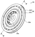
- the blower 30 has a flat disk shape as shown in FIG.
- FIG. 3 is a perspective view showing the appearance of the blower 30 alone.
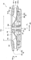
- 4 is a sectional view taken along the line IV-IV of FIG. 3, that is, an axial sectional view of the blower 30 cut along a plane including the fan axis CL.
- An arrow DRa in FIG. 4 indicates the axial direction of the fan axis CL, that is, the fan axis direction DRa.
- the blower 30 is an all-round blow type centrifugal blower, and more specifically, a turbo fan having receding blades.
- the blower 30 includes a blower case 32 that is a casing of the blower 30, a rotating shaft 34, an electric motor 36, a centrifugal fan 38, and the like.
- the blower case 32 accommodates an electric motor 36 and a centrifugal fan 38, and includes a first case member 321 and a second case member 322.
- the blower case 32 protects the electric motor 36 and the centrifugal fan 38 from external dust and dirt.
- the first case member 321 constitutes a portion on the cushion member 121a side in the fan axial direction DRa, that is, one portion, and the second case member 322 constitutes the other portion.
- the cushion member 121a is shown in FIG.
- the first case member 321 and the second case member 322 are integrated with each other by being fastened with screws.
- the first case member 321 and the second case member 322 have a plurality of cylindrical pillars projecting to the other side at the peripheral portion, and the first case member 321 and the second case member 322 include the plurality of pillars. They are fastened to each other by screws inserted therethrough.
- the first case member 321 is formed with an intake port 30a through which the blower 30 sucks air.
- the intake port 30a has a circular shape, and the center of the intake port 30a coincides with the fan axis CL.
- the bell mouth that is usually provided around the intake port in the centrifugal blower is not provided in the blower 30 of the present embodiment. That is, there is no bulging of the first case member 321 around the intake port 30a toward the outside of the case in the fan axial direction DRa.
- the intake port 30a is formed on the outer surface 321b of the blower case 32 facing the cushion air passage 121c in the fan axial direction DRa, and the outer surface 321b of the blower case 32 on which the intake port 30a is formed is a smooth surface. It has become.
- peripheral portion 321a of the first case member 321 and the peripheral portion 322a of the second case member 322 are provided apart from each other in the fan axial direction DRa, and the blower 30 is provided between the peripheral portions 321a and 322a. It becomes the blower outlet 30b which blows off air.
- the blower outlet 30b of the blower 30 is formed over the entire circumference of the blower case 32 around the fan axis CL. Therefore, the blower 30 blows out air from the entire circumference of the blower case 32 around the fan axis CL.
- the rotary shaft 34 is a cylindrical bar as shown in FIG. 4 and is supported by the second case member 322 via a bearing 341. Therefore, the rotation shaft 34 is rotatable about the fan axis CL with respect to the second case member 322.
- the rotating shaft 34 protrudes into the blower case 32, and a main plate 383 of the centrifugal fan 38 is connected to the protruding portion so as not to be relatively rotatable. As a result, the rotating shaft 34 rotates integrally with the centrifugal fan 38 about the fan axis CL.
- the electric motor 36 is an outer rotor type brushless DC motor, and is disposed between the main plate 383 of the centrifugal fan 38 and the second case member 322 in the fan axial direction DRa.
- the second case member 322 is also configured to function as a motor housing for the electric motor 36.
- the electric motor 36 rotates the centrifugal fan 38 around the fan axis CL when energized.
- the electric motor 36 includes a motor rotor 361 and a motor stator 362.
- the motor rotor 361 includes a permanent magnet and is fixed to the main plate 383 of the centrifugal fan 38.
- the motor stator 362 includes a coil and is provided on the inner peripheral side of the motor rotor 361.
- the motor stator 362 is fixed to the second case member 322.
- the centrifugal fan 38 is a centrifugal multiblade fan, that is, an impeller of a centrifugal blower.
- the centrifugal fan 38 includes a plurality of blades 381 disposed around the fan axis CL, an annular side plate 382, and a main plate 383.
- the centrifugal fan 38 rotates around the fan axis CL to suck air from the outside of the blower 30 through the intake port 30a and blow out the sucked air to the outside of the blower 30 through the blowout port 30b. .
- the blower 30 sucks air into the blower 30 from the intake port 30a and blows air out of the blower 30 through the outlet 30b by the rotation of the centrifugal fan 38. 2 and 4, the air blown from the outlet 30b of the blower 30 to the cushion back space 121h including the space outside the blower 30 is from the cushion back space 121h to the vehicle seat 12 in the vehicle interior. It flows out.
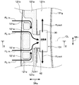
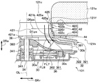
- the air passage forming member 42 is interposed between the cushion member 121a and the blower 30 in the fan axial direction DRa, as shown in FIG. 5 which is a VV cross-sectional view of FIG. 2, for example, the cushion member 121a and the blower 30.
- the air passage forming member 42 has a cylindrical duct portion 422, a first flange portion 423 that extends in a bowl shape from one end of the duct portion 422 on the cushion member 121a side, and a bowl shape from the other end of the duct portion 422 on the blower 30 side. And a second flange portion 424 extending in the direction.
- the air passage forming member 42 is made of, for example, an elastic material such as rubber, and the duct portion 422, the first flange portion 423, and the second flange portion 424 of the air passage forming member 42 are integrally formed.
- a connecting air passage 421 is formed inside the duct portion 422.
- the first flange portion 423 is pressed against the cushion member 121a in the fan axial direction DRa.
- the second flange portion 424 is pressed in the fan axis direction DRa against the first case member 321 of the blower 30 via a packing material 44 formed in an annular shape around the fan axis CL and made of, for example, urethane foam. ing.
- connection air passage 421 is connected to the opening end 121f of the cushion air passage 121c, and the other end of the connection air passage 421 opposite to the cushion air passage 121c (that is, the blower 30 side) is the other end of the blower 30. It is connected to the intake port 30a.
- the air inlet 30a of the blower 30 communicates with the cushion air passage 121c via the connection air passage 421, and the air in the cushion air passage 121c passes through the air passage forming member 42. Led to. Then, the centrifugal fan 38 of the blower 30 sucks the air in the cushion air passage 121c through the connection air passage 421 and the intake port 30a in order by rotating around the fan axis CL.
- the duct portion 422 of the air passage forming member 42 has an air passage inner wall surface 425 inside the duct portion 422.
- the air passage inner wall surface 425 forms a wall surface of the connection air passage 421.
- the passage cross section of the connection air passage 421 has a circular shape centered on the fan axis CL.
- the passage cross section is a cross section orthogonal to the air flow direction in the connection air passage 421.
- the air passage inner wall surface 425 has a downstream edge 425 a at the downstream end in the air flow in the connection air passage 421, that is, the blower 30 side end.
- the downstream edge 425a is formed in a circular shape centering on the fan axis CL, and forms an air flow downstream end 421a which is a connection end 421a to the intake port 30a of the blower 30 in the connection air passage 421.
- the downstream edge 425a of the air passage inner wall surface 425 coincides with the peripheral edge 421b of the air flow downstream end 421a of the connection air passage 421.
- the passage downstream end diameter D1ps which is the diameter of the air flow downstream end 421a of the connection air passage 421, matches the intake port diameter Din, which is the diameter of the intake port 30a of the blower 30.
- the relationship between the passage downstream end diameter D1ps and the intake diameter Din is preferably “(D1ps ⁇ Din) /Din ⁇ 0.05”.
- connection air passage 421 is arranged so that the peripheral edge 421b of the downstream end 421a of the connection air passage 421 and the peripheral edge 30c of the air inlet 30a of the blower 30 are aligned when viewed from the fan axial direction DRa. It can be said that it is established.
- the air passage inner wall surface 425 of the air passage forming member 42 has a constricted portion 425b in the middle of the air passage inner wall surface 425 in the fan axial direction DRa.
- the constricted portion 425b is a convex surface that bulges inward in the radial direction DRr of the fan shaft center CL, and constricts the middle of the connection air passage 421 in the fan shaft direction DRa.
- the diameter D2ps at the apex of the constricted portion 425b is the minimum inner diameter of the air passage inner wall surface 425, that is, the minimum passage diameter of the connection air passage 421, and therefore is smaller than the passage downstream end diameter D1ps of the connection air passage 421.
- the air passage inner wall surface 425 has a sloped surface 425c on the air flow downstream side of the air passage inner wall surface 425, specifically, on the air flow downstream side from the apex of the constricted portion 425b.
- the inclined surface 425c forms a connection air passage 421 so that the cross section of the connection air passage 421 becomes wider toward the downstream end 421a of the connection air passage 421.
- the slope surface 425c is formed such that the inner diameter of the air passage inner wall surface 425 increases toward the downstream side of the air flow in the air passage inner wall surface 425.
- the inclined surface 425c partially overlaps with the constricted portion 425b, and is provided in a range from the apex of the constricted portion 425b to the downstream end edge 425a in the fan axial direction DRa.
- the air flowing through the connection air passage 421 of the air passage formation member 42 flows from the connection air passage 421 to the intake port of the blower 30 as indicated by arrows FL1 and FL2. It flows to the centrifugal fan 38 through 30a.
- Arrows FL1 and FL2 in FIG. 5 indicate air flows FL1 and FL2 that flow from the connection air passage 421 to the centrifugal fan 38 through the air inlet 30a of the blower 30, and in particular, the arrow FL1 is on the inner wall 425 of the air passage. The air flow FL1 which flows along is shown.
- the air passage forming member 42 has a diameter of the fan shaft center CL that is larger than the air flow in which the air flowing along the air passage inner wall surface 425 of the air flowing through the connection air passage 421 faces the fan shaft center direction DRa.
- An air flow (that is, an air flow FL1) directed outward in the direction DRr is formed at the air flow downstream end 421a of the connection air passage 421.
- the air flow FL ⁇ b> 1 flowing along the air passage inner wall surface 425 faces the outside in the oblique radial direction DRr with respect to the fan axis CL at the air flow downstream end 421 a of the connection air passage 421.
- a magnetic flux change is generated in the core by the coil of the motor stator 362 energized from the external power source, and the permanent magnet (in other words, a magnet) fixed to the motor rotor 361.
- the permanent magnet in other words, a magnet
- a force that pulls Since the motor rotor 361 is fixed to the rotation shaft 34 supported by the center piece of the second case member 322 via the bearing 341, the motor rotor 361 receives the force attracting the permanent magnet around the fan axis CL. Rotating motion.
- the centrifugal fan 38 is fixed to the motor rotor 361 and rotates integrally with the rotating shaft 34 and the motor rotor 361, so that a plurality of blades 381 of the centrifugal fan 38 impart momentum to the air, and the outer periphery of the centrifugal fan 38 is Air is sent out from the section. Then, the air sucked from the air inlet 30 a of the blower 30 and sent out by the blade 381 of the centrifugal fan 38 is discharged to the outside through the blower outlet 30 b of the blower 30.
- the blower 30 generates an air flow as shown by an arrow FLin in FIG. That is, the blower 30 generates an air flow that sequentially passes through the skin cover 121b, the cushion air passage 121c of the cushion member 121a, and the connection air passage 421 of the air passage forming member 42 from the seat surface side by the operation of the blower 30. At the same time, the blower 30 blows air to the cushion back surface space 121h as indicated by an arrow FLout.
- the structure of the 1st ventilation unit 101 provided in the seat back part 121 of the vehicle seat 12 of FIG. 1 is as above-mentioned
- the structure of the 2nd ventilation unit 102 provided in the seat seat part 122 is also the 1st.
- the structure is the same as that of the one air blowing unit 101.
- the air passage forming member 42 is such that the air flowing along the air passage inner wall surface 425 out of the air flowing through the connection air passage 421
- An air flow (that is, an air flow FL1) directed outward in the radial direction DRr of the fan shaft center CL as compared with an air flow directed in the direction DRa is formed at the air flow downstream end 421a of the connection air passage 421. It is arranged. Therefore, the air flow flowing between the blades 381 of the centrifugal fan 38 is not easily disturbed without the bell mouth protruding around the air inlet 30a of the blower 30 in the fan axial direction DRa being provided in the blower case 32.
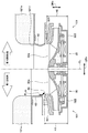
- FIG. 6 is a cross-sectional view of the first blower unit 101 corresponding to FIG. 5.
- the first blower unit 101 of the present embodiment is illustrated on the right side of the fan axis CL while the left side of the fan axis CL is illustrated.
- These are the figures which illustrated the 1st ventilation unit 101 of the 1st comparative example contrasted with this embodiment.
- the bell case 46 is provided in the first case member 321 of the blower 30 included in the first blower unit 101, but the bell mouth 46 is provided in the blower 30 of the present embodiment. Is not provided.
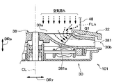
- the thickness H2 of the blower 30 of this embodiment in the fan axial direction DRa is larger than the thickness H1 of the blower 30 of the first comparative example. small. That is, by omitting the bell mouth 46, the fan 30 is flattened in the fan axial direction DRa in the present embodiment as compared with the first comparative example.
- the total thickness of the first blower unit 101 in this embodiment that is, the total thickness including the blower 30 and the air passage forming member 42 is compared with the total thickness of the first blower unit 101 in the first comparative example. And it is getting smaller.
- FIG. 7 is a cross-sectional view of the first blower unit 101 in the second comparative example compared with the present embodiment, and corresponds to FIG. 5 of the present embodiment.
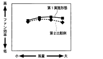
- 8 is a diagram comparing the fan efficiency of the blower 30 between the present embodiment and the second comparative example of FIG. 7 is a conduit that guides the air flowing out from the cushion air passage 121c to the air inlet 30a of the blower 30, similarly to the air passage forming member 42 of the present embodiment shown in FIG.
- the several arrow described in the duct 48 and the air blower 30 in FIG. 7 has shown the air flow.
- the blower 30 included in the second comparative example of FIG. 7 is the same as the blower 30 of this embodiment, and the second comparative example is obtained by replacing the air passage forming member 42 of the first embodiment with a duct 48. .
- the present embodiment has the following effects. That is, depending on the relative positional relationship between the air flow downstream end 421a of the connection air passage 421 of the air passage formation member 42 shown in FIG. 5 and the intake port 30a of the blower 30, and the constricted shape of the connection air passage 421, FIG. As indicated by the arrows FL1 and FL2, the contracted flow at the intake port 30a can be suppressed. And the air which flows in into the inlet 30a of the air blower 30 can be guide
- the fan efficiency of the blower 30 in the present embodiment indicated by the solid line is higher than the fan efficiency of the blower 30 in the second comparative example indicated by the broken line.
- connection air passage 421 of the air passage forming member 42 is connected to the peripheral edge 421 b of the air flow downstream end 421 a of the connection air passage 421 and the blower 30 when viewed from the fan axial direction DRa. It arrange
- a configuration is assumed in which the peripheral edge 421b of the air flow downstream end 421a of the connection air passage 421 is located outside the peripheral edge 30c of the air inlet 30a of the blower 30 in the radial direction DRr of the fan axis CL.
- the air flow flowing out from the connection air passage 421 along the air passage inner wall surface 425 collides with a part of the first case member 321 forming the peripheral edge 30c of the intake port 30a and has a diameter. It faces in the direction DRr. For example, it faces the inner side of the radial direction DRr like the air flow indicated by the arrow FLm in FIG. 6 or the arrow FLn in FIG.
- connection air passage 421 it is possible to avoid the air flow flowing out from the connection air passage 421 along the air passage inner wall surface 425 from being directed inward in the radial direction DRr.
- the air flowing along the inner wall surface 425 of the air passage is caused by the arrangement of the connection air passage 421 relative to the air inlet 30a of the blower 30 at the downstream end 421a of the connection air passage 421. It is possible to avoid turning inward in the radial direction DRr. And the disturbance of the air flow in the air flow downstream end 421a of the connection air passage 421 can be suppressed.
- the air flow downstream end 421a of the connection air passage 421 faces outward in the radial direction DRr of the fan shaft center CL compared to the fan shaft center direction DRa.
- the air flow (that is, the air flow FL1 in FIG. 5) that has been generated can be formed into the air that flows along the inner wall surface 425 of the air passage.
- the air flow flowing between the blades 381 of the centrifugal fan 38 in the blower 30 can be an air flow that is directed outward in the radial direction DRr of the fan shaft center CL as compared to the fan shaft direction DRa. .
- the air passage inner wall surface 425 of the air passage forming member 42 has the constricted portion 425b that constricts the middle of the connection air passage 421. That is, by providing the constricted portion 425b, the air passage inner wall surface 425 has a sloped surface 425c that expands the cross section of the connection air passage 421 closer to the air flow downstream end 421a of the connection air passage 421, and the constriction portion 425b. It is on the downstream side of the air flow from the apex. Therefore, it is possible to form an air flow that is inclined outwardly in the radial direction DRr of the fan shaft center CL at the downstream end 421a of the connection air passage 421 with respect to the fan shaft center direction DRa.
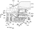
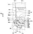
- FIG. 9 is a VV (see FIG. 2) sectional view showing a schematic configuration of the first blower unit 101 in the present embodiment, and corresponds to FIG. 5 of the first embodiment. As shown in FIG. 9, in the present embodiment, the shape of the duct portion 422 of the air passage forming member 42 is different from that of the first embodiment.
- the duct portion 422 of the air passage forming member 42 has a straight pipe shape extending in the fan axial direction DRa. Therefore, the connection air passage 421 formed in the duct portion 422 extends in the fan axial direction DRa with a constant passage cross section over the entire length of the connection air passage 421. That is, since the passage diameter D3ps of the connection air passage 421 is the same size over the entire length of the connection air passage 421, the passage diameter D3ps is the same size as the passage downstream end diameter D1ps.
- the passage downstream end diameter D1ps of the connection air passage 421 is equal to the intake diameter Din of the blower 30 as in the first embodiment. Also in this embodiment, for example, the relationship between the passage downstream end diameter D1ps and the intake diameter Din is preferably “(D1ps ⁇ Din) /Din ⁇ 0.05”.
- the air flowing through the connecting air passage 421 of the air passage forming member 42 is blown from the connecting air passage 421 as indicated by arrows FL3 and FL4. It flows to the centrifugal fan 38 through 30 intake ports 30a.
- the arrows FL3 and FL4 in FIG. 9 indicate the air flows FL3 and FL4 that flow from the connection air passage 421 to the centrifugal fan 38 through the intake port 30a of the blower 30.
- the arrow FL3 is on the air passage inner wall surface 425. The air flow FL3 which flows along is shown.
- the air passage forming member 42 connects the air flow (that is, the air flow FL3) in which the air flowing along the air passage inner wall surface 425 out of the air flowing through the connection air passage 421 faces the fan axial direction DRa.
- the air passage 421 is disposed so as to be formed at the air flow downstream end 421a.
- the connecting air passage 421 of the air passage forming member 42 extends in the fan axial direction DRa with a constant passage cross section. Therefore, compared with the first embodiment in which the middle of the connection air passage 421 is constricted, the change in the area of the passage cross section of the connection air passage 421 as a whole with respect to the intake port 30a of the blower 30 is small. It is possible to suppress the pressure loss of the air flow flowing into 30a.
- the air flow flowing along the air passage inner wall surface 425 is inclined with respect to the fan axis CL in the first embodiment as shown by an arrow FL1 in FIG. 5 at the air flow downstream end 421a of the connection air passage 421. It faces the outside in the radial direction DRr.
- the air flow flowing along the air passage inner wall surface 425 is directed to the fan axial direction DRa at the downstream end 421a of the connection air passage 421 as indicated by an arrow FL3 in FIG. . Therefore, in this embodiment, the effect of suppressing the disturbance of the air flow flowing between the blades 381 of the centrifugal fan 38 cannot be expected as much as in the first embodiment, but the effect is more effective than the second comparative example of FIG. Can get big.
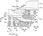
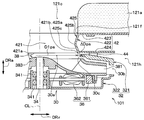
- FIG. 10 is a VV (see FIG. 2) sectional view showing a schematic configuration of the first blower unit 101 in the present embodiment, and corresponds to FIG. 5 of the first embodiment. As shown in FIG. 10, in the present embodiment, the shape of the duct portion 422 of the air passage forming member 42 is different from that of the first embodiment.
- the duct portion 422 of the air passage forming member 42 includes a duct downstream end portion 422a provided on the downstream side in the air flow in the connection air passage 421, and an upstream portion in the air flow from the duct downstream end portion 422a.
- a duct cylindrical portion 422b having a cylindrical straight pipe shape extending to the side.
- the duct downstream end portion 422a swells radially inward of the duct portion 422 with respect to the duct cylindrical portion 422b, and has an annular shape centering on the fan axis CL.
- the duct downstream end 422a has a shape corresponding to a bell mouth.
- the air passage inner wall surface 425 which is the inner wall surface of the duct portion 422 is divided into the inner wall surface downstream end portion 425d which is the inner wall surface of the duct downstream end portion 422a and the large diameter wall surface portion 425e which is the inner wall surface of the duct cylindrical portion 422b. And have.
- the inner wall downstream end 425d is provided on the downstream side of the air passage inner wall 425, and the large-diameter wall 425e extends from the inner wall downstream end 425d to the upstream side of the air flow.
- the inner diameter D4ps is larger than the intake port 30a.
- the passage cross section of the large diameter wall surface portion 425e is constant over the entire length of the large diameter wall surface portion 425e. Further, since the inner wall downstream end 425d is provided on the downstream side of the air flow of the air passage inner wall 425, the downstream edge of the inner wall downstream end 425d is the downstream edge 425a of the air passage inner wall 425. is there.
- the inner wall downstream end portion 425d included in the air passage inner wall surface 425 is formed in an annular shape around the fan axis CL in detail.
- the cross-sectional shape of the inner wall downstream end portion 425d has an arc shape bulging toward the connecting air passage 421 as shown in FIG. 10, for example, a 1/4 arc shape.
- the radius Rs of the cross section of the inner wall downstream end portion 425d having the arc shape is, for example, 2.5 mm or more.
- the tangent line that contacts the inner wall downstream end portion 425d at the downstream edge 425a of the air passage inner wall surface 425 faces the fan axial direction DRa.
- downstream end diameter D1ps of the connection air passage 421 and the intake diameter Din of the blower 30 in the present embodiment is the same as that in the first embodiment described above. That is, the passage downstream end diameter D1ps of the connection air passage 421 is equal to the intake opening diameter Din of the blower 30.
- the inlet diameter Din is shown in FIG.
- the air flowing along the air passage inner wall surface 425 of the air passage forming member 42 is connected air passages as indicated by arrows FL5 and FL6. It flows from 421 to the air inlet 30a of the blower 30.
- Arrows FL5 and FL6 in FIG. 10 indicate air flows FL5 and FL6 that flow along the air passage inner wall surface 425 from the connection air passage 421 to the air inlet 30a of the blower 30.
- the arrow FL5 indicates the air flow FL5 at the air flow downstream end 421a of the connection air passage 421.
- the tangent line that contacts the inner wall downstream end portion 425d at the downstream edge 425a of the air passage inner wall surface 425 faces the fan axial direction DRa.
- the air flow FL5 at the air flow downstream end 421a of the connection air passage 421 faces the fan axial direction DRa. That is, the air passage forming member 42 connects the air flow (that is, the air flow FL5) in which the air flowing along the air passage inner wall surface 425 out of the air flowing through the connection air passage 421 faces the fan axial direction DRa.
- the air passage 421 is disposed so as to be formed at the air flow downstream end 421a.
- FIG. 11 is a VV (see FIG. 2) sectional view showing a schematic configuration of the first blower unit 101 in the present embodiment, and corresponds to FIG. 5 of the first embodiment.
- the shape of the duct part 422 of the air path formation member 42 differs from 1st Embodiment.
- the duct portion 422 of the air passage forming member 42 includes a duct enlarged portion 422c whose inner diameter increases toward the downstream side in the air flow in the connection air passage 421, and a duct cylindrical portion 422b.
- the duct cylindrical portion 422b has a cylindrical straight pipe shape extending from the duct enlarged diameter portion 422c to the upstream side in the air flow.
- the air passage inner wall surface 425 which is the inner wall surface of the duct portion 422, has a gradient surface 425f, which is the inner wall surface of the duct enlarged portion 422c, and a cylindrical wall surface portion 425g, which is the inner wall surface of the duct cylindrical portion 422b. Yes.
- the gradient surface 425f is provided on the air flow downstream side of the air passage inner wall surface 425.
- the sloped surface 425f is tapered, and the connection air passage 421 is formed so that the cross section of the connection air passage 421 becomes wider as it is closer to the air flow downstream end 421a of the connection air passage 421.
- the cylindrical wall surface portion 425g included in the air passage inner wall surface 425 extends from the gradient surface 425f to the upstream side of the air flow and has an inner diameter D5ps smaller than the air inlet 30a of the blower 30.
- the passage cross section of the cylindrical wall surface portion 425g is constant over the entire length of the cylindrical wall surface portion 425g. Further, since the slope surface 425f is provided on the downstream side of the air flow of the air passage inner wall surface 425, the downstream edge of the slope surface 425f is the downstream edge 425a of the air passage inner wall surface 425.
- downstream end diameter D1ps of the connection air passage 421 and the intake diameter Din of the blower 30 in the present embodiment is the same as that in the first embodiment described above. That is, the passage downstream end diameter D1ps of the connection air passage 421 is equal to the intake opening diameter Din of the blower 30.
- the inlet diameter Din is shown in FIG.
- the air flowing through the connecting air passage 421 of the air passage forming member 42 is blown from the connecting air passage 421 as indicated by arrows FL7 and FL8. It flows to the centrifugal fan 38 through 30 intake ports 30a.
- the arrows FL7 and FL8 in FIG. 11 indicate the air flows FL7 and FL8 that flow from the connection air passage 421 to the centrifugal fan 38 through the intake port 30a of the blower 30, and in particular, the arrow FL7 is on the air passage inner wall surface 425. The air flow FL7 which flows along is shown.
- the air flowing along the air passage inner wall surface 425 out of the air flowing through the connection air passage 421 is an air flow (ie, an air flow that faces the outside in the oblique radial direction DRr with respect to the fan axial direction DRa).
- the air flow FL7) is arranged to be formed at the air flow downstream end 421a of the connection air passage 421.
- FIG. 12 is a partial cross-sectional view of the first blower unit 101 in the present embodiment, and is an enlarged view corresponding to the XII portion of FIG.
- the shape of the peripheral part of the side plate 382 of the centrifugal fan 38 and the inlet 30a of the blower case 32 is different from that of the second embodiment.
- each of the plurality of blades 381 has one end 381b on the side of the air inlet 30a in the fan axial direction DRa, and the plurality of blades 381 are arranged at one end 381b of the side plate 382. Each is connected.
- the side plate 382 has a first side surface 382a that faces the main plate 383, and a second side surface 382b that is the side surface opposite to the first side surface 382a. That is, in the side plate 382, the first side surface 382a is provided on the blade connection side to which the blade 381 is connected, and the second side surface 382b is provided on the opposite side to the blade connection side.
- the side plate 382 has an inner end edge portion 382 c provided on the inner side in the radial direction of the side plate 382.
- the surface of the inner edge 382c is a curved surface 382d.
- the curved surface 382d of the inner edge 382c is a curved surface that is continuously curved and curved from the first side surface 382a to the second side surface 382b.
- the curved surface 382d has an arc shape connected from the first side surface 382a to the second side surface 382b on the cross section including the fan axis CL (for example, the cross section shown in FIG. 12).
- the first case member 321 of the blower case 32 has an opposing wall surface 321c that opposes the second side surface 382b of the side plate 382, and an opposing curved surface 321d that opposes the curved surface 382d of the side plate 382.
- the facing wall surface 321c of the blower case 32 faces the second side surface 382b of the side plate 382 with a gap 321e therebetween.
- the opposing wall surface 321c has a shape along the second side surface 382b, for example, a shape in which the second side surface 382b is offset.
- the opposed curved surface 321d of the blower case 32 is a curved surface continuously connected from the opposed wall surface 321c, and is opposed to the curved surface 382d of the side plate 382 with a gap 321f.
- the opposing curved surface 321d has a shape along the curved surface 382d, for example, a shape obtained by offsetting the curved surface 382d.
- the gap 321f between the curved surface 382d and the opposed curved surface 321d has the same width as the gap 321e between the second side surface 382b and the opposed wall surface 321c, and any of the gaps 321e and 321f has a uniform width. It has become.
- the air flowing through the cushion air passage 121c of the vehicle seat 12 flows through the connection air passage 421 of the air passage formation member 42 in accordance with the rotation of the centrifugal fan 38, and the air inlet 30a of the blower 30. Flow into. At this time, a pressure difference is generated between the air inlet 30a and the air outlet 30b shown in FIG. 9 along with the air flow.
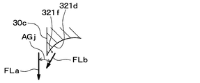
- the opposing curved surface 321d of the blower case 32 extends to the inner side of the inner peripheral end 382e of the side plate 382 in the radial direction DRr of the fan shaft center CL in order to suppress the disturbance of the air flow at the time of merging. It is. Then, as shown in FIGS. 12 and 13, the opposed curved surface 321 d guides the merged air so that the merged angle AGj of the merged air becomes an acute angle.
- the merged air merges into the mainstream air flowing between the plurality of blades 381 from the intake port 30a as indicated by an arrow FLa from an air gap 321f between the opposed curved surface 321d and the curved surface 382d as indicated by an arrow FLb. Air.
- the merged air merge angle AGj is an angle formed by the flow direction of the merged air with respect to the flow direction of the mainstream air when the merged air merges with the mainstream air.
- FIG. 13 is an enlarged view of a portion XIII in FIG.
- the inner edge 382 c of the side plate 382 is configured by a curved surface 382 d that is curved from the first side surface 382 a to the second side surface 382 b and continuously continues.
- the opposing wall surface 321c of the blower case 32 faces the second side surface 382b with a gap 321e therebetween, and has a shape along the second side surface 382b.
- the opposing curved surface 321d of the blower case 32 is continuously connected to the opposing wall surface 321c, is opposed to the curved surface 382d of the side plate 382 with a gap 321f, and has a shape along the curved surface 382d. Yes.
- the merging air that flows back through the gaps 321e and 321f between the first case member 321 and the side plate 382 of the centrifugal fan 38 is rectified, and the merging angle AGj shown in FIG. 13 is reduced. Thereby, it is possible to merge the merged air with the mainstream air while suppressing the disturbance of the air flow.
- the mainstream air is rectified by the connecting air passage 421 of the air passage forming member 42 and guided to the intake port 30a, the turbulent energy generated by joining the joined air can be reduced.
- the opposing curved surface 321d of the blower case 32 extends to the inner side of the inner peripheral end 382e of the side plate 382 in the radial direction DRr of the fan shaft center CL.
- the extension line Lex of the peripheral edge 30c of the intake port 30a is a curve that is offset from the first side surface 382a of the side plate 382 by the proportion occupied by the merged air.
- the merged air (for example, merged air flowing as indicated by the arrow FLd) that flows out from the gap 321f between the curved surface 382d and the opposing curved surface 321d and the mainstream air (for example, as indicated by the arrow FLa) from the intake port 30a.
- Main flow air can flow in parallel between the blades 381. Furthermore, turbulent energy that can be generated by the combined air and the main air can be reduced.
- the opposing curved surface 321d of the blower case 32 shown in FIG. 12 and FIG. 13 joins the mainstream air from the intake port 30a from the gap 321f between the opposing curved surface 321d and the curved surface 382d as indicated by the arrow FLb.
- the merging air is guided so that the merging angle AGj of the air becomes an acute angle. Therefore, for example, as compared with the case where the merging angle AGj becomes an obtuse angle, it is possible to suppress the turbulence of the air flow due to the merging of the merging air and the mainstream air.
- FIG. 14 is a graph comparing the relationship between the flow coefficient ⁇ and the specific noise Ks in the blower 30 between the present embodiment and the second embodiment described above.
- a curve NS2 in FIG. 14 shows the above relationship of the second embodiment, and a curve NS5 shows the above relationship of the present embodiment.
- the gap 321f between the curved surface 382d and the opposed curved surface 321d has the same width as the gap 321e between the second side surface 382b and the opposed wall surface 321c. Therefore, for example, compared with a configuration in which the former gap 321f is larger than the latter gap 321e, the flow rate of the combined air that flows backward through the gaps 321e and 321f, that is, the leakage flow rate of the blower 30 is reduced. It is possible to improve the efficiency of the blower 30.
- this embodiment is a modification based on 2nd Embodiment, it is also possible to combine this embodiment with the above-mentioned 1st, 3rd, or 4th embodiment.
- the air passage forming member 42 is made of an elastic material such as rubber, but the material is not limited.
- the air passage forming member 42 is more rigid than rubber or the like. However, it may be made of high plastic.
- the air passage forming member 42 may be made of the same material as the packing material 44 having sealability by being crushed, such as urethane foam. If so, it is possible to connect the connection air passage 421 to the air inlet 30a of the blower 30 without the need for the packing material 44.
- the duct portion 422 in which the connection air passage 421 is formed has a cylindrical shape, but it is only necessary that the connection air passage 421 be formed inside the duct portion 422. There is no limitation on the outer shape of the duct portion 422.
- the cross section of the connection air passage 421 has a circular shape centered on the fan axis CL, but the shape of the cross section of the passage is not limited.
- the connection air passage 421 may have a rectangular or elliptical cross section.
- the shape of the air flow downstream end 421a of the connection air passage 421, and the shape of the air flow downstream end 421a may be, for example, a rectangular shape or an elliptical shape. That is, the air flow downstream end 421a does not need to have the same shape as the air inlet 30a of the blower 30 having a circular shape.
- the passage downstream end diameter D1ps of the connection air passage 421 is equal to the intake diameter Din of the blower 30, but not limited thereto.
- the passage downstream end diameter D1ps may be equal to or smaller than the intake diameter Din.
- the connection air passage 421 of the air passage formation member 42 is configured so that the entire air flow downstream end 421a of the connection air passage 421 falls within the range occupied by the intake port 30a when viewed from the fan axial direction DRa. It may be arranged. The same applies to the second to fourth embodiments.
- FIG. 15 shows a modification as an example in which the passage downstream end diameter D1ps is equal to or smaller than the intake diameter Din.
- the passage downstream end diameter D1ps is smaller than the intake opening diameter Din by the difference width ⁇ Dps between the passage downstream end opening diameter D1ps and the intake opening diameter Din.
- the connection air passage 421 is configured so that the entire air flow downstream end 421a of the connection air passage 421 falls within the range occupied by the intake port 30a when viewed from the fan axial direction DRa. It is arranged. Therefore, in the modification of FIG.
- FIG. 15 is a VV (see FIG. 2) cross-sectional view showing a schematic configuration of the first blower unit 101 in the modification of the first embodiment, and corresponds to FIG. 5 of the first embodiment. is there. Further, when viewed from the fan axis direction DRa, the range occupied by the intake port 30a is specifically within the range of a circular region centered on the fan axis CL and having the intake port diameter Din as the diameter. It is.
- the vehicle seat air-conditioning apparatus 10 includes two air blowing units 101 and 102.
- the vehicle seat air conditioner 10 may include one air blowing unit or three or more air blowing units.
- the vehicle seat air conditioner 10 is a device that allows air to flow through the seat back portion 121 and the seat seat portion 122 of the vehicle seat 12, but allows air to flow through portions other than the seat back portion 121 and the seat seat portion 122. It may be a thing.
- the second side surface 382b of the side plate 382 included in the centrifugal fan 38 is configured as a smooth surface, but may be configured including unevenness. The same applies to the first to fourth embodiments.
Landscapes
- Engineering & Computer Science (AREA)
- Mechanical Engineering (AREA)
- General Engineering & Computer Science (AREA)
- Aviation & Aerospace Engineering (AREA)
- Transportation (AREA)
- Thermal Sciences (AREA)
- Physics & Mathematics (AREA)
- Chemical & Material Sciences (AREA)
- Combustion & Propulsion (AREA)
- Structures Of Non-Positive Displacement Pumps (AREA)
- Air-Conditioning For Vehicles (AREA)
- Chair Legs, Seat Parts, And Backrests (AREA)
- Seats For Vehicles (AREA)
Abstract
Description
車両用シートのクッション部材に形成されたクッション空気通路へ連結される連結空気通路が形成されており、その連結空気通路の壁面を成す空気通路内壁面を有する空気通路形成部材と、
連結空気通路のクッション空気通路側とは反対側に連結された吸気口が形成された送風機ケース、および、その送風機ケース内に収容されており、ファン軸心まわりに回転することでクッション空気通路内の空気を連結空気通路と吸気口とを順に介して吸い込む遠心ファンを有する送風機とを備え、
空気通路形成部材は、連結空気通路を流れる空気のうち空気通路内壁面に沿って流れる空気が、ファン軸心の軸方向を向いた空気流れ又はその軸方向を向いた空気流れと比較してファン軸心の径方向外側へ向いた空気流れを連結空気通路の空気流れ下流端にて形成するように配設される。
図1は、第1実施形態において車両用シート空調装置10とその車両用シート空調装置10によって通風される車両用シート12とを示した斜視図である。図1において矢印DR1は車両の左右方向DR1すなわち車両幅方向DR1を表し、矢印DR2は車両の上下方向DR2すなわち車両上下方向DR2を表し、矢印DR3は車両の前後方向DR3すなわち車両前後方向DR3を表している。また、図1では車両用シート12が部分的に断面図示されている。
次に、第2実施形態について説明する。本実施形態では、前述の第1実施形態と異なる点を主として説明し、第1実施形態と同一または均等な部分については省略または簡略化して説明する。後述の第3実施形態以降でも同様である。
次に、第3実施形態について説明する。本実施形態では、前述の第1実施形態と異なる点を主として説明する。
次に、第4実施形態について説明する。本実施形態では、前述の第1実施形態と異なる点を主として説明する。
次に、第5実施形態について説明する。本実施形態では、前述の第2実施形態と異なる点を主として説明する。
(1)上述の各実施形態において、空気通路形成部材42はゴム等の弾性材で構成されているが、その材質に限定はなく、例えば空気通路形成部材42は、ゴム等と比較して剛性が高いプラスチック等で構成されていても差し支えない。
Claims (9)
- 送風ユニットであって、
車両用シート(12)のクッション部材(121a)に形成されたクッション空気通路(121c)へ連結される連結空気通路(421)が形成されており、該連結空気通路の壁面を成す空気通路内壁面(425)を有する空気通路形成部材(42)と、
前記連結空気通路の前記クッション空気通路側とは反対側に連結された吸気口(30a)が形成された送風機ケース(32)、および、該送風機ケース内に収容されており、ファン軸心(CL)まわりに回転することで前記クッション空気通路内の空気を前記連結空気通路と前記吸気口とを順に介して吸い込む遠心ファン(38)を有する送風機(30)とを備え、
前記空気通路形成部材は、前記連結空気通路を流れる空気のうち前記空気通路内壁面に沿って流れる空気が、前記ファン軸心の軸方向(DRa)を向いた空気流れ又は該軸方向を向いた空気流れと比較して前記ファン軸心の径方向(DRr)外側へ向いた空気流れを前記連結空気通路の空気流れ下流端(421a)にて形成するように配設される送風ユニット。 - 前記連結空気通路は、前記軸方向から見たときに前記連結空気通路の空気流れ下流端の全体が、前記吸気口が占める範囲内に入るように配設される請求項1に記載の送風ユニット。
- 前記連結空気通路は、前記軸方向から見たときに前記連結空気通路の空気流れ下流端の周縁(421b)と前記吸気口の周縁(30c)とが揃うように配設される請求項1に記載の送風ユニット。
- 前記空気通路内壁面は、前記連結空気通路の途中を括れさせる括れ部(425b)を有している請求項1ないし3のいずれか1つに記載の送風ユニット。
- 前記空気通路内壁面は、前記連結空気通路の通路断面を前記空気流れ下流端に近いほど拡げる勾配面(425c、425f)を空気流れ下流側に有している請求項1ないし3のいずれか1つに記載の送風ユニット。
- 前記空気通路内壁面は、該空気通路内壁面の空気流れ下流側に設けられた内壁面下流端部(425d)と、該内壁面下流端部から空気流れ上流側へ延び前記吸気口よりも大きい内径(D4ps)を有する大径壁面部(425e)とを有し、
前記内壁面下流端部は前記ファン軸心まわりに環状に形成され、前記ファン軸心を含む断面において前記内壁面下流端部の断面形状は前記連結空気通路側へ膨らんだ円弧状を成している請求項1ないし3のいずれか1つに記載の送風ユニット。 - 前記連結空気通路は一定の通路断面で前記軸方向に延びている請求項1ないし3のいずれか1つに記載の送風ユニット。
- 前記遠心ファンは、前記軸方向での前記吸気口側に一端(381b)を有し前記ファン軸心まわりに配置された複数枚のブレード(381)と、該複数枚のブレードが前記一端にてそれぞれ連結された環状の側板(382)とを有し、
前記側板は、前記ブレードが連結されているブレード連結側に設けられた第1側面(382a)と、該ブレード連結側とは反対側に設けられた第2側面(382b)と、前記側板の径方向内側に設けられ、前記第1側面から前記第2側面にかけて湾曲し連続的に連なる湾曲面(382d)で構成された内側端縁部(382c)とを有し、
前記送風機ケースは、前記第2側面に対して空隙(321e)を空けて対向し該第2側面に沿った形状を成す対向壁面(321c)と、該対向壁面から連続的に連なり、前記湾曲面に対して空隙(321f)を空けて対向し該湾曲面に沿った形状を成す対向湾曲面(321d)とを有している請求項1ないし7のいずれか1つに記載の送風ユニット。 - 前記対向湾曲面は、
前記ファン軸心の径方向において前記側板の内周端(382e)よりも内側にまで及んでおり、
前記吸気口から前記複数枚のブレードの相互間へ流れる主流空気へ前記対向湾曲面と前記湾曲面との間の空隙から合流する合流空気の合流角度(AGj)が鋭角になるように該合流空気を導く請求項8に記載の送風ユニット。
Priority Applications (4)
| Application Number | Priority Date | Filing Date | Title |
|---|---|---|---|
| CN201680007343.8A CN107206924B (zh) | 2015-02-16 | 2016-01-07 | 送风单元 |
| US15/547,586 US10123628B2 (en) | 2015-02-16 | 2016-01-07 | Blower unit |
| DE112016000766.3T DE112016000766B4 (de) | 2015-02-16 | 2016-01-07 | Gebläse-Einheit |
| JP2017500536A JP6299925B2 (ja) | 2015-02-16 | 2016-01-07 | 送風ユニット |
Applications Claiming Priority (4)
| Application Number | Priority Date | Filing Date | Title |
|---|---|---|---|
| JP2015027739 | 2015-02-16 | ||
| JP2015-027739 | 2015-02-16 | ||
| JP2015132650 | 2015-07-01 | ||
| JP2015-132650 | 2015-07-01 |
Publications (1)
| Publication Number | Publication Date |
|---|---|
| WO2016132757A1 true WO2016132757A1 (ja) | 2016-08-25 |
Family
ID=56688919
Family Applications (1)
| Application Number | Title | Priority Date | Filing Date |
|---|---|---|---|
| PCT/JP2016/050391 Ceased WO2016132757A1 (ja) | 2015-02-16 | 2016-01-07 | 送風ユニット |
Country Status (5)
| Country | Link |
|---|---|
| US (1) | US10123628B2 (ja) |
| JP (1) | JP6299925B2 (ja) |
| CN (1) | CN107206924B (ja) |
| DE (1) | DE112016000766B4 (ja) |
| WO (1) | WO2016132757A1 (ja) |
Cited By (9)
| Publication number | Priority date | Publication date | Assignee | Title |
|---|---|---|---|---|
| JP2018075916A (ja) * | 2016-11-08 | 2018-05-17 | トヨタ紡織株式会社 | 乗物用シート送風装置、及び乗物用シート |
| JP2018100601A (ja) * | 2016-12-19 | 2018-06-28 | 株式会社Soken | 遠心送風機 |
| JP2018103656A (ja) * | 2016-12-22 | 2018-07-05 | トヨタ紡織株式会社 | 乗物用シート送風装置、及び乗物用シート |
| JP2018127098A (ja) * | 2017-02-08 | 2018-08-16 | 株式会社デンソー | シート送風装置 |
| WO2018169316A1 (ko) * | 2017-03-17 | 2018-09-20 | 주식회사 아모텍 | 쿨링 팬 및 이를 구비한 시트 쿨링장치 |
| KR20180106828A (ko) * | 2017-03-17 | 2018-10-01 | 주식회사 아모텍 | 쿨링 팬 및 이를 구비한 시트 쿨링장치 |
| WO2019111517A1 (ja) * | 2017-12-05 | 2019-06-13 | シナノケンシ株式会社 | モータ装置及び車載シート空調装置 |
| CN111267713A (zh) * | 2020-03-20 | 2020-06-12 | 韩文飞 | 一种生鲜产品长途运输车 |
| WO2022124054A1 (ja) * | 2020-12-11 | 2022-06-16 | 株式会社デンソー | シート空調装置 |
Families Citing this family (9)
| Publication number | Priority date | Publication date | Assignee | Title |
|---|---|---|---|---|
| JP6493620B2 (ja) * | 2016-02-24 | 2019-04-03 | 株式会社デンソー | 遠心送風機 |
| JP7152672B2 (ja) * | 2017-05-23 | 2022-10-13 | テイ・エス テック株式会社 | 乗物用シート |
| US10252652B2 (en) * | 2017-08-29 | 2019-04-09 | Ford Global Technologies, Llc | Seating assembly with heating and cooling |
| US10821803B2 (en) | 2017-08-29 | 2020-11-03 | Ford Global Technologies, Llc | Vehicle seat with cooling fluidflow |
| US10507745B2 (en) | 2017-08-29 | 2019-12-17 | Ford Global Technologies, Llc | Seating assembly with thermoelectric devices |
| FR3072912B1 (fr) * | 2017-10-27 | 2019-11-01 | Faurecia Sieges D'automobile | Element de siege avec un systeme de ventilation |
| CN108891314A (zh) * | 2018-08-16 | 2018-11-27 | 席格科技(北京)有限公司 | 一种汽车座椅按摩通风系统及方法 |
| WO2021059899A1 (ja) * | 2019-09-27 | 2021-04-01 | 株式会社デンソー | 送風機 |
| KR20210103617A (ko) * | 2020-02-13 | 2021-08-24 | 현대자동차주식회사 | 시트백 통풍 구조 |
Citations (5)
| Publication number | Priority date | Publication date | Assignee | Title |
|---|---|---|---|---|
| JPH04347398A (ja) * | 1991-05-24 | 1992-12-02 | Fuji Electric Co Ltd | ターボブロワの吸込み口 |
| JPH10184594A (ja) * | 1996-12-20 | 1998-07-14 | Daikin Ind Ltd | ベルマウス |
| JP2005348997A (ja) * | 2004-06-11 | 2005-12-22 | Matsushita Electric Ind Co Ltd | 車両用シート装置 |
| US20090152909A1 (en) * | 2007-12-12 | 2009-06-18 | Lear Corporation | Attachment assembly for securing trim material to the padding of a ventilated seat |
| US20120080911A1 (en) * | 2010-08-27 | 2012-04-05 | Amerigon Incorporated | Fluid distribution features for climate controlled seating assemblies |
Family Cites Families (20)
| Publication number | Priority date | Publication date | Assignee | Title |
|---|---|---|---|---|
| JPS6460799A (en) | 1987-08-28 | 1989-03-07 | Matsushita Refrigeration | Centrifugal blower |
| US5296769A (en) * | 1992-01-24 | 1994-03-22 | Electrolux Corporation | Air guide assembly for an electric motor and methods of making |
| JP3391361B2 (ja) | 1993-12-17 | 2003-03-31 | 株式会社デンソー | 多翼送風機 |
| JP3952536B2 (ja) | 1997-05-29 | 2007-08-01 | 株式会社デンソー | スクロールケーシング |
| JP3861674B2 (ja) * | 2001-11-30 | 2006-12-20 | 株式会社デンソー | 車両用シート空調装置および空調装置内蔵型車両用シート |
| JP2004148949A (ja) * | 2002-10-30 | 2004-05-27 | Denso Corp | 車両用空調装置 |
| DE10351805A1 (de) | 2002-11-08 | 2004-05-27 | Denso Corp., Kariya | Fahrzeugsitzklimaanlage |
| KR100878247B1 (ko) * | 2002-12-04 | 2009-01-13 | 조규호 | 통풍시트 |
| JP3876830B2 (ja) | 2002-12-10 | 2007-02-07 | 株式会社デンソー | 遠心式送風機及び空調装置用の送風機 |
| JP3698150B2 (ja) | 2003-05-09 | 2005-09-21 | ダイキン工業株式会社 | 遠心送風機 |
| JP4513555B2 (ja) | 2004-12-24 | 2010-07-28 | 株式会社デンソー | 車両用シート空調装置 |
| JP2007240046A (ja) * | 2006-03-07 | 2007-09-20 | Denso Corp | 空調装置 |
| US8313284B2 (en) * | 2006-07-21 | 2012-11-20 | Panasonic Corporation | Centrifugal fan device and eletronic device having the same |
| JP4865497B2 (ja) | 2006-10-19 | 2012-02-01 | 三菱重工業株式会社 | 遠心式送風装置 |
| JP4910809B2 (ja) | 2007-03-20 | 2012-04-04 | 株式会社デンソー | 遠心式送風機 |
| JP5131093B2 (ja) | 2008-08-29 | 2013-01-30 | 株式会社デンソー | 遠心式送風機 |
| JP2010133297A (ja) | 2008-12-03 | 2010-06-17 | Daikin Ind Ltd | 遠心送風機 |
| CN104822562B (zh) * | 2012-12-05 | 2016-09-28 | 松下知识产权经营株式会社 | 交通工具用供暖装置以及带供暖的交通工具用座椅 |
| US9421893B2 (en) * | 2013-01-23 | 2016-08-23 | Panasonic Intellectual Property Management Co., Ltd. | Vehicle heating device and heater-equipped vehicle seat |
| KR102412277B1 (ko) * | 2014-09-03 | 2022-06-27 | 코웨이 주식회사 | 원심 송풍기 |
-
2016
- 2016-01-07 JP JP2017500536A patent/JP6299925B2/ja active Active
- 2016-01-07 US US15/547,586 patent/US10123628B2/en active Active
- 2016-01-07 DE DE112016000766.3T patent/DE112016000766B4/de not_active Expired - Fee Related
- 2016-01-07 CN CN201680007343.8A patent/CN107206924B/zh active Active
- 2016-01-07 WO PCT/JP2016/050391 patent/WO2016132757A1/ja not_active Ceased
Patent Citations (5)
| Publication number | Priority date | Publication date | Assignee | Title |
|---|---|---|---|---|
| JPH04347398A (ja) * | 1991-05-24 | 1992-12-02 | Fuji Electric Co Ltd | ターボブロワの吸込み口 |
| JPH10184594A (ja) * | 1996-12-20 | 1998-07-14 | Daikin Ind Ltd | ベルマウス |
| JP2005348997A (ja) * | 2004-06-11 | 2005-12-22 | Matsushita Electric Ind Co Ltd | 車両用シート装置 |
| US20090152909A1 (en) * | 2007-12-12 | 2009-06-18 | Lear Corporation | Attachment assembly for securing trim material to the padding of a ventilated seat |
| US20120080911A1 (en) * | 2010-08-27 | 2012-04-05 | Amerigon Incorporated | Fluid distribution features for climate controlled seating assemblies |
Cited By (16)
| Publication number | Priority date | Publication date | Assignee | Title |
|---|---|---|---|---|
| JP2018075916A (ja) * | 2016-11-08 | 2018-05-17 | トヨタ紡織株式会社 | 乗物用シート送風装置、及び乗物用シート |
| JP2018100601A (ja) * | 2016-12-19 | 2018-06-28 | 株式会社Soken | 遠心送風機 |
| JP2018103656A (ja) * | 2016-12-22 | 2018-07-05 | トヨタ紡織株式会社 | 乗物用シート送風装置、及び乗物用シート |
| JP2018127098A (ja) * | 2017-02-08 | 2018-08-16 | 株式会社デンソー | シート送風装置 |
| CN110291296A (zh) * | 2017-03-17 | 2019-09-27 | 阿莫泰克有限公司 | 冷却风扇及具有其的座椅冷却装置 |
| KR20180106828A (ko) * | 2017-03-17 | 2018-10-01 | 주식회사 아모텍 | 쿨링 팬 및 이를 구비한 시트 쿨링장치 |
| KR101990108B1 (ko) * | 2017-03-17 | 2019-06-18 | 주식회사 아모텍 | 쿨링 팬 및 이를 구비한 시트 쿨링장치 |
| WO2018169316A1 (ko) * | 2017-03-17 | 2018-09-20 | 주식회사 아모텍 | 쿨링 팬 및 이를 구비한 시트 쿨링장치 |
| EP3597929A4 (en) * | 2017-03-17 | 2020-12-16 | Amotech Co., Ltd. | COOLING FAN AND SEAT COOLING SYSTEM INCLUDING IT |
| US11420544B2 (en) | 2017-03-17 | 2022-08-23 | Amotech Co., Ltd. | Cooling fan and seat cooling device comprising same |
| WO2019111517A1 (ja) * | 2017-12-05 | 2019-06-13 | シナノケンシ株式会社 | モータ装置及び車載シート空調装置 |
| CN111267713A (zh) * | 2020-03-20 | 2020-06-12 | 韩文飞 | 一种生鲜产品长途运输车 |
| WO2022124054A1 (ja) * | 2020-12-11 | 2022-06-16 | 株式会社デンソー | シート空調装置 |
| JP2022093094A (ja) * | 2020-12-11 | 2022-06-23 | 株式会社デンソー | シート空調装置 |
| JP7452401B2 (ja) | 2020-12-11 | 2024-03-19 | 株式会社デンソー | シート空調装置 |
| US12539733B2 (en) | 2020-12-11 | 2026-02-03 | Denso Corporation | Seat air-conditioning device |
Also Published As
| Publication number | Publication date |
|---|---|
| US20180020838A1 (en) | 2018-01-25 |
| DE112016000766T5 (de) | 2018-01-18 |
| JP6299925B2 (ja) | 2018-03-28 |
| DE112016000766B4 (de) | 2023-03-30 |
| CN107206924B (zh) | 2019-05-31 |
| JPWO2016132757A1 (ja) | 2017-08-17 |
| CN107206924A (zh) | 2017-09-26 |
| US10123628B2 (en) | 2018-11-13 |
Similar Documents
| Publication | Publication Date | Title |
|---|---|---|
| JP6299925B2 (ja) | 送風ユニット | |
| CN106103151B (zh) | 座椅空调系统 | |
| JP3698150B2 (ja) | 遠心送風機 | |
| JP5259164B2 (ja) | 送風機の羽根車 | |
| CN104024649B (zh) | 轴流风扇 | |
| JP6652077B2 (ja) | 遠心送風機 | |
| JP2023118734A (ja) | 渦流ブロワ | |
| JP6421881B2 (ja) | ターボファン | |
| US20190390676A1 (en) | Centrifugal blower device | |
| US11332052B2 (en) | Centrifugal blower device | |
| JP2018135876A (ja) | 遠心送風機 | |
| JP6314998B2 (ja) | 遠心ファンの羽根車 | |
| JP3876830B2 (ja) | 遠心式送風機及び空調装置用の送風機 | |
| JP2015124624A (ja) | 送風機 | |
| JP2004316448A (ja) | 遠心送風機 | |
| WO2022085332A1 (ja) | 送風機 | |
| WO2008056740A1 (en) | Air conditioner | |
| JP2011226408A (ja) | 多翼ファン | |
| JP2001317494A (ja) | 遠心式送風機 | |
| JP5255491B2 (ja) | ファン用ケーシング | |
| JP2023136901A (ja) | 遠心送風装置 | |
| WO2020144945A1 (ja) | 遠心式送風機 | |
| JP5255490B2 (ja) | ファン用ケーシング | |
| JP6181908B2 (ja) | ブロワ | |
| JP2004144033A (ja) | ダクトファン |
Legal Events
| Date | Code | Title | Description |
|---|---|---|---|
| 121 | Ep: the epo has been informed by wipo that ep was designated in this application |
Ref document number: 16752146 Country of ref document: EP Kind code of ref document: A1 |
|
| ENP | Entry into the national phase |
Ref document number: 2017500536 Country of ref document: JP Kind code of ref document: A |
|
| WWE | Wipo information: entry into national phase |
Ref document number: 15547586 Country of ref document: US |
|
| WWE | Wipo information: entry into national phase |
Ref document number: 112016000766 Country of ref document: DE |
|
| 122 | Ep: pct application non-entry in european phase |
Ref document number: 16752146 Country of ref document: EP Kind code of ref document: A1 |