WO2016132463A1 - 自動車用ドアラッチ装置 - Google Patents
自動車用ドアラッチ装置 Download PDFInfo
- Publication number
- WO2016132463A1 WO2016132463A1 PCT/JP2015/054348 JP2015054348W WO2016132463A1 WO 2016132463 A1 WO2016132463 A1 WO 2016132463A1 JP 2015054348 W JP2015054348 W JP 2015054348W WO 2016132463 A1 WO2016132463 A1 WO 2016132463A1
- Authority
- WO
- WIPO (PCT)
- Prior art keywords
- release
- lever
- locking
- unlocking
- motor
- Prior art date
Links
Images


Classifications
-
- E—FIXED CONSTRUCTIONS
- E05—LOCKS; KEYS; WINDOW OR DOOR FITTINGS; SAFES
- E05B—LOCKS; ACCESSORIES THEREFOR; HANDCUFFS
- E05B81/00—Power-actuated vehicle locks
- E05B81/12—Power-actuated vehicle locks characterised by the function or purpose of the powered actuators
- E05B81/16—Power-actuated vehicle locks characterised by the function or purpose of the powered actuators operating on locking elements for locking or unlocking action
-
- E—FIXED CONSTRUCTIONS
- E05—LOCKS; KEYS; WINDOW OR DOOR FITTINGS; SAFES
- E05B—LOCKS; ACCESSORIES THEREFOR; HANDCUFFS
- E05B81/00—Power-actuated vehicle locks
- E05B81/12—Power-actuated vehicle locks characterised by the function or purpose of the powered actuators
- E05B81/14—Power-actuated vehicle locks characterised by the function or purpose of the powered actuators operating on bolt detents, e.g. for unlatching the bolt
-
- E—FIXED CONSTRUCTIONS
- E05—LOCKS; KEYS; WINDOW OR DOOR FITTINGS; SAFES
- E05B—LOCKS; ACCESSORIES THEREFOR; HANDCUFFS
- E05B85/00—Details of vehicle locks not provided for in groups E05B77/00 - E05B83/00
- E05B85/02—Lock casings
-
- E—FIXED CONSTRUCTIONS
- E05—LOCKS; KEYS; WINDOW OR DOOR FITTINGS; SAFES
- E05B—LOCKS; ACCESSORIES THEREFOR; HANDCUFFS
- E05B77/00—Vehicle locks characterised by special functions or purposes
- E05B77/22—Functions related to actuation of locks from the passenger compartment of the vehicle
- E05B77/30—Functions related to actuation of locks from the passenger compartment of the vehicle allowing opening by means of an inner door handle, even if the door is locked
-
- E—FIXED CONSTRUCTIONS
- E05—LOCKS; KEYS; WINDOW OR DOOR FITTINGS; SAFES
- E05B—LOCKS; ACCESSORIES THEREFOR; HANDCUFFS
- E05B79/00—Mounting or connecting vehicle locks or parts thereof
- E05B79/02—Mounting of vehicle locks or parts thereof
- E05B79/08—Mounting of individual lock elements in the lock, e.g. levers
-
- E—FIXED CONSTRUCTIONS
- E05—LOCKS; KEYS; WINDOW OR DOOR FITTINGS; SAFES
- E05B—LOCKS; ACCESSORIES THEREFOR; HANDCUFFS
- E05B81/00—Power-actuated vehicle locks
- E05B81/02—Power-actuated vehicle locks characterised by the type of actuators used
- E05B81/04—Electrical
-
- E—FIXED CONSTRUCTIONS
- E05—LOCKS; KEYS; WINDOW OR DOOR FITTINGS; SAFES
- E05B—LOCKS; ACCESSORIES THEREFOR; HANDCUFFS
- E05B81/00—Power-actuated vehicle locks
- E05B81/02—Power-actuated vehicle locks characterised by the type of actuators used
- E05B81/04—Electrical
- E05B81/06—Electrical using rotary motors
-
- E—FIXED CONSTRUCTIONS
- E05—LOCKS; KEYS; WINDOW OR DOOR FITTINGS; SAFES
- E05B—LOCKS; ACCESSORIES THEREFOR; HANDCUFFS
- E05B81/00—Power-actuated vehicle locks
- E05B81/24—Power-actuated vehicle locks characterised by constructional features of the actuator or the power transmission
- E05B81/32—Details of the actuator transmission
- E05B81/34—Details of the actuator transmission of geared transmissions
- E05B81/36—Geared sectors, e.g. fan-shaped gears
-
- E—FIXED CONSTRUCTIONS
- E05—LOCKS; KEYS; WINDOW OR DOOR FITTINGS; SAFES
- E05B—LOCKS; ACCESSORIES THEREFOR; HANDCUFFS
- E05B81/00—Power-actuated vehicle locks
- E05B81/24—Power-actuated vehicle locks characterised by constructional features of the actuator or the power transmission
- E05B81/32—Details of the actuator transmission
- E05B81/42—Cams
-
- E—FIXED CONSTRUCTIONS
- E05—LOCKS; KEYS; WINDOW OR DOOR FITTINGS; SAFES
- E05B—LOCKS; ACCESSORIES THEREFOR; HANDCUFFS
- E05B81/00—Power-actuated vehicle locks
- E05B81/24—Power-actuated vehicle locks characterised by constructional features of the actuator or the power transmission
- E05B81/50—Powered actuators with automatic return to the neutral position by non-powered means, e.g. by springs
-
- E—FIXED CONSTRUCTIONS
- E05—LOCKS; KEYS; WINDOW OR DOOR FITTINGS; SAFES
- E05B—LOCKS; ACCESSORIES THEREFOR; HANDCUFFS
- E05B81/00—Power-actuated vehicle locks
- E05B81/54—Electrical circuits
- E05B81/64—Monitoring or sensing, e.g. by using switches or sensors
- E05B81/72—Monitoring or sensing, e.g. by using switches or sensors the lock status, i.e. locked or unlocked condition
-
- E—FIXED CONSTRUCTIONS
- E05—LOCKS; KEYS; WINDOW OR DOOR FITTINGS; SAFES
- E05B—LOCKS; ACCESSORIES THEREFOR; HANDCUFFS
- E05B81/00—Power-actuated vehicle locks
- E05B81/54—Electrical circuits
- E05B81/64—Monitoring or sensing, e.g. by using switches or sensors
- E05B81/76—Detection of handle operation; Detection of a user approaching a handle; Electrical switching actions performed by door handles
-
- Y—GENERAL TAGGING OF NEW TECHNOLOGICAL DEVELOPMENTS; GENERAL TAGGING OF CROSS-SECTIONAL TECHNOLOGIES SPANNING OVER SEVERAL SECTIONS OF THE IPC; TECHNICAL SUBJECTS COVERED BY FORMER USPC CROSS-REFERENCE ART COLLECTIONS [XRACs] AND DIGESTS
- Y10—TECHNICAL SUBJECTS COVERED BY FORMER USPC
- Y10T—TECHNICAL SUBJECTS COVERED BY FORMER US CLASSIFICATION
- Y10T292/00—Closure fasteners
- Y10T292/08—Bolts
- Y10T292/1043—Swinging
- Y10T292/1075—Operating means
- Y10T292/1082—Motor
Definitions
- the present invention relates to a door latch device for an automobile.
- the vehicle door latch device includes a meshing mechanism for holding the door in the closed position by meshing with the striker on the vehicle body side, and an operation mechanism for operating the meshing mechanism, and is provided on the door for opening the door Manual release type in which the meshing mechanism can be disengaged by a mechanical element (lever, link, etc.) that operates based on the operation of a mechanical operation element (outside handle or inside handle), and door opening operation provided on the door It is classified into an electric release type in which the engagement of the meshing mechanism can be released by an electric element such as a motor driven based on the operation of the electric operation element (operation switch).
- the manual release type door latch device enables the door opening operation of the mechanical operation element based on the driving of the locking and unlocking motor and the locking and unlocking motor.
- Disengagement consisting of mechanical elements such as levers and links that can be selectively switched to an unlocked state enabling disengagement of the engagement mechanism and a locked state disabling the opening operation and disabling the engagement of the engagement mechanism
- a lock mechanism in Patent Document 1, an operation mechanism.
- the release motor that can be driven based on the operation of the door-opening switch provided on the door and the drive of the motor rotate and the meshing state of the meshing mechanism It has an electric release mechanism including a releasable output lever, and an open lever pivotally supported coaxially with the output lever. Furthermore, the ratchet lever for releasing the meshing mechanism is linked via the first wire to an external control lever provided at a predetermined position outside the vehicle which is not used in normal operation. Also, the open lever is linked to an internal control lever provided inside the vehicle via a second wire. Further, switching between the unlocking state for enabling the operation of the door opening switch and the locking state for disabling the operation is performed by electrical control of a control device mounted on the vehicle.
- the door latch device described in Patent Document 2 is wirelessly performed between an electronic key (portable device in Patent Document 2) possessed by an authorized user of the vehicle and an authentication unit mounted on the vehicle. If the ID signal matches in the communication and the authorized user approaches the car, then the release motor is driven to control the ratchet lever when the authorized user operates the door opening switch. Activate to disengage the meshing mechanism and allow the door to open.
- the ratchet lever is actuated to release the meshing of the meshing mechanism and allow the door to be opened.
- the door can not be opened even by a passenger who does not have the electronic key, unless the authorized user approaches the car and the authentication unit authenticates the ID signal. .
- the vehicle door latch device described in Patent Document 3 includes, as main elements, a release motor, an open lever that can be rotated by driving the motor, and an internal mechanical operation element provided on the inner side surface of the door (see Patent Document 3).
- the inside lever is linked to the "inside handle", the open link which can release the meshing of the meshing mechanism by the operation of the inside lever and the open lever, and the key lever linked to the key cylinder provided on the vehicle outer surface of the door.
- the open link is locked by a drive source such as a motor, thereby disabling the opening operation of the internal mechanical operation element, in addition to the electrical control of the control device. ing.
- the door latch device described in Patent Document 3 drives and controls the release motor to operate the release motor when the open switch provided on the door is operated while the control device is controlling the unlock state. Release the meshing of the door to allow the door to open. Further, when a trouble occurs in the electrical system, regardless of the unlock state or the lock state, the operation of the key cylinder releases the meshing of the meshing mechanism to enable the door to be opened.
- the present invention has an object of providing a door latch device for an automobile, which can be downsized in a configuration provided with a release motor, a locking / unlocking motor, and a locking / unlocking mechanism.
- a meshing unit including a body and a meshing mechanism accommodated in the body and meshable with the striker, an operation mechanism capable of operating the meshing mechanism, and a housing fixed to the body and housing the operation mechanism.
- the operating mechanism includes a locking and unlocking motor, a locking and unlocking pivoting body rotatable based on the driving of the locking and unlocking motor, and a rotation of the locking and unlocking pivoting body.
- a lock mechanism comprising a mechanical element selectively switchable between an unlocked state for enabling an open door operation of an external mechanical operation element outside the vehicle and a locked state, and the locking / unlocking mechanism
- a release motor disposed below the motor, and pivoted on the housing by a release shaft, and rotated based on the drive of the release motor, and the state of the locking and unlocking mechanism
- an electric release lever capable of releasing the meshing of the meshing mechanism independently, and an approach route when the striker enters the striker insertion groove provided in the body and meshes with the meshing mechanism is a striker entry line X
- the locking and unlocking motor is arranged such that its own case is higher than the striker approach line X, and the release motor is such that its own case is lower than the striker approach line X It is characterized by being placed in
- a straight line contacting the upper end of the release motor and extending backward is a straight line D
- a straight line contacting a lower end of the release motor and extending backward is a straight line E
- the straight line E is a range F
- the release axis is disposed within the range F.
- the release motor is arranged such that an output shaft pivotally supported by the case of itself is directed downward.
- the locking and unlocking motor is arranged such that its case is higher than the striker approach line X
- the release motor is arranged such that its own case is lower than the striker approach line X
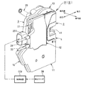
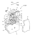
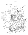
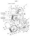
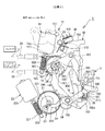
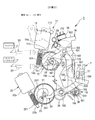
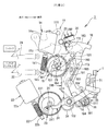
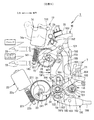
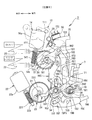
- FIG. 1 is a side view of an automobile provided with a door latch device for an automobile according to the present invention. It is a perspective view of a door latch device common to each specification. It is a partial disassembled perspective view of the door latch apparatus common to each specification.
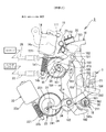
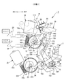
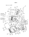
- FIG. 5 is a partial exploded perspective view of the door latch device in specification 1; It is an exploded perspective view of a door latch device similarly. It is a rear view of a door latch device common to each specification. It is a side view of the principal part when a locking and unlocking mechanism is in an unlocking state in specification 1. It is a side view of the principal part when it is in a lock state similarly. It is a side view of the principal part of the state which carried out electric release operation in the unlocking state similarly.
- FIG. 10 is a side view of the main parts when the locking and unlocking mechanism is in the unlocked state in specification 2; It is a side view of the principal part when it is in a lock state similarly. It is a side view of the principal part of the state which carried out manual release operation similarly in the locked state. It is a side view of the principal part when the locking and unlocking mechanism is in the unlocking state in the specification 3. It is a side view of the principal part when it is in a lock state similarly.
- FIG. 18 is an exploded perspective view of the main part in the specification 4; It is a side view of the principal part when the locking and unlocking mechanism is in the unlocking state and the child proof mechanism is in the child unlocking state as well. Similarly in the unlocking state and the child unlocking state, it is a side view of the main part in the manual release operating state. It is a side view of the principal part when it is in an unlocking state and a child lock state similarly.
- a door latch device 1F for the front door for holding the front door FD in the closed position is provided on the front door FD of the four-door type automobile V, and an external mechanical operation element provided outside the vehicle.
- a key cylinder KC for switching operation and a lock knob (not shown) for selectively switching the locking / unlocking mechanism between the lock state and the unlock state from inside the vehicle are arranged. Note that any one of specifications 1 to 3 described later is set in the door latch device 1F.
- a door latch device 1R for a rear door for holding the rear door RD in a closed position an outside handle OH of an external mechanical operation element provided outside the vehicle, a detection switch SW of an electrical detection element, and a car
- An inside handle IH of an internal mechanical operation element provided inside and a lock knob (not shown) for selectively switching the locking / unlocking mechanism from the inside of the vehicle to the locked state and the unlocked state are arranged. Specification 4 or 5 described later is set in the door latch device 1R.
- the detection switch SW of the electrical detection element is installed on the front surface, the back surface, or in the vicinity of each outside handle OH, and is configured by a capacitive touch switch that detects that the user touches it.
- the authorized user carrying the key approaches the vehicle V within a predetermined area, and matching of the ID signal in wireless communication performed between the electronic key and the receiver mounted on the vehicle V matches,
- the control is electrically controlled by a control device ECU (Electronic Control Unit) mounted on the vehicle V so that the detection of the user becomes effective only when it is determined that the authorized user approaches the vehicle V.
- the detection switch SW is not limited to the touch switch, and may be a proximity switch that detects that a part of the human body approaches.
- FIGS. 7 to 11 are operation explanatory diagrams of the main part in the specification 1.
- the direction used by the following description points out the state which attached door latch apparatus 1F, 1R to each door FD, RD.
- the door latch device 1F is mounted in the front door FD, and is engaged with the striker S on the vehicle body side to hold the front door FD in the closed position, and the engagement unit 2 having the engagement mechanism, and the front door FD in locked state or And an operation unit 3 having a locking / unlocking mechanism constituted by mechanical elements (lever, link, etc.) selectively switchable to the unlocked state.
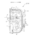
- the meshing unit 2 is housed as a main element in a body 4 fixed to a rear end portion in the front door FD by a plurality of bolts (not shown), and housed in the body 4 In a direction to release the engagement relationship between the ratchet 6 and the latch 5 and a meshing mechanism (not shown) including the latch 5 meshable with the striker S fixed to the vehicle body side and the ratchet 6 engageable with the latch 5
- a metal inertia lever 37 pivotally supported by a release operable open lever 7 (for example, see FIGS. 4 and 5) and a shaft 31 directed in the front-rear direction for supporting an outside lever 21 described later.
- a release operable open lever 7 for example, see FIGS. 4 and 5
- the latch 5 is pivotally supported within the body 4 by a latch shaft 8 directed in the front-rear direction, and a striker provided on the body 4 with a full latch engagement portion 51 and a half latch engagement portion 52 engageable with the ratchet 6.
- the striker S that has entered the entry groove 41 and the meshing groove 53 that can be engaged.
- the striker entry groove 41 of the body 4 is provided slightly higher than the approximate center in the vertical direction, and has a shape in which the inside of the vehicle opens and extends in the outward direction.
- the symbol “X” shown in FIG. 6 indicates a striker entry line, which is an entry route when the striker S enters the striker entry groove 41 and meshes with the meshing groove 53 of the latch 5 when the front door FD is closed. Show.
- the latch 5 is an open position corresponding to the open state of the front door FD not engaged with the striker S along with the closing operation of the front door FD (a position rotated approximately 90 degrees clockwise from the position shown in FIG. ) against a biasing force of a spring (not shown), and is engaged with the striker S that has entered along the striker entry line X from the left into the striker entry groove 41 in FIG. It passes through the half latch position corresponding to the half door state where the groove 53 is slightly meshed, and turns to the fully latched position (position shown in FIG. 6) corresponding to the fully closed state in which the meshing groove 53 completely meshes with the striker S. Also, as the striker S exits from the striker approach groove 41 due to the opening operation of the front door FD, it pivots in the opposite direction.
- the ratchet 6 is below the striker entry groove 41 and is pivotally supported within the body 4 by the ratchet shaft 9 facing in the front-rear direction, and in the engagement direction (counterclockwise in FIG. 6) by a spring (not shown)
- the front door FD is held in a fully closed state by being urged toward the full latch engagement portion 51 and half latch engagement portion 52 of the latch 5 and engaged with the full latch engagement portion 51. Also, by engaging the half latch engagement portion 52, the front door FD is maintained in the half door state.
- the inertia lever 37 is pivotally supported by the shaft 31 so that the center of gravity thereof is located at the center of the shaft 31, and a spring 38 whose one end is hooked to a protrusion 371 provided on the front side always rotates clockwise in FIG. It is biased to stop at the standby position.
- An end (not shown) of the outer side of the open lever 7 that rotates integrally with the ratchet 6 is in contact with the protrusion 371 on the side opposite to the side where the one end of the spring 38 is latched.
- the open lever 7 is pivotally supported on the front side of the body 4 coaxially with the ratchet 6 so as to be able to rotate integrally with the ratchet 6 and extends inward of the vehicle
- a to-be-released part 71 is provided at the end.
- the operation unit 3 closes the first cover 10 made of a synthetic resin substantially L-shaped in plan view and fixed to the body 4 so as to cover the front surface of the body 4 and the side of the first cover 10 facing the vehicle interior.
- the second cover 11 made of synthetic resin
- the waterproof side cover 12 made of synthetic resin closing the side surface of the substantially upper half of the second cover 11 from the inside of the vehicle, and the first cover 10 and the second cover 11 It has a water proof top cover 13 that covers the upper mating surface, and an operating mechanism (no reference numeral) housed in the housing.
- the “in housing” used in the present description is a housing formed between the side surface of the first cover 10 substantially perpendicular to the front surface of the body 4 and the side surface of the second cover 11 facing the side surface. It points to space.
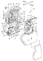
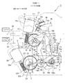
- the operation mechanism includes, as basic elements, a locking and unlocking motor 14 and a locking and unlocking worm wheel 15 (locking and unlocking pivoting body) that can be rotated forward and reverse by driving the locking and unlocking motor 14.
- a lock lever 16 movable to an unlock position enabling and a lock position disabling the front door FD, an open link 18 movable together with the lock lever 16 to an unlock position and a lock position, a front door FD
- the inside lever 19 of the inside operation system in specification 1 linked to the inside handle IH and the key lever 20 interlocked with the operation of the key cylinder KC of the front door FD (the door latch device 1R for the rear door is not provided) Release with the outside lever 21 linked to the outside handle OH of the door FD, and release The release operation (rotation in the clockwise direction in FIG.
- the release worm wheel 23 (release pivoting body) that can be rotated by driving the motor 22 and the release motor 22 and the release worm wheel 23 It is comprised including the possible electric release lever 24, the wiring plate 25 to which the wiring electrically connected to the motor 14 for locking / unlocking, the motor 22 for release and locking, and various detection switches was given. Further, in the accommodation space between the second cover 11 and the waterproof side cover 12, a knob lever 17 linked to a manual operation lock knob (not shown) provided inside the front door FD is provided.
- the inside lever 19 which is an element of the inside operation system is set to a configuration according to each specification as described later.
- the operation mechanism in the operation unit 3 constitutes a basic structure by a set of elements excluding the inside lever 19 (including the key lever 20 in the door latch device 1R for the rear door) from the above-described basic elements.
- a locking and unlocking mechanism is constituted by the locking worm wheel 15 which is a mechanical element, the lock lever 16 and the knob lever 17.
- the “unlocked state” used in the following description refers to the state in which the lock lever 16, the knob lever 17 and the open link 18 are in the unlocked position, and the “locked state” refers to the lock lever 16, The knob lever 17 and the open link 18 are in the lock position.
- the configuration of the locking and unlocking mechanism is not limited to the present embodiment, and for example, the knob lever 17 may be omitted and the lock lever 16 may be linked to the lock knob.
- the release motor 22, the release worm wheel 23 and the electric release lever 24 constitute an electric release mechanism.
- the locking and unlocking motor 14 is housed in the housing, and its case (yoke) 14a is higher than the striker approach line X shown in FIG. 6, and the output shaft 14b pivoted on the case 14a is directed downward. It is disposed as described above, and is driven by operation of an operation switch (not shown) provided in the car or an electronic key possessed by the user. As described above, by arranging the locking and unlocking motor 14 in the housing such that the case 14a is located above the striker approach line X, the rainwater invading from the striker approach groove 41 may enter the case 14a. To prevent.
- the wiring plate 25 integrally forms a coupler 251 to which an on-board battery (not shown) and an external connector (not shown) of an external electric wire connected to the control unit ECU are connected, and a housing on the side facing the outside Wiring is provided for power supply to the inside and output of various signals, and the case 14a of the locking and unlocking motor 14 is fixed in the housing so as to cover the inside of the vehicle.
- the wiring of the wiring plate 25 is an external connector connected to the terminals of the locking and unlocking motor 14 and releasing motor 22 and the coupler 251 so that the locking and unlocking motor 14 and release motor 22 can be controlled by the control unit ECU. Are electrically connected to each other. In FIG. 4, the wiring plate 25 is omitted to clearly show the internal structure of the operation unit 3.
- the locking / unlocking worm wheel 15 is pivotally supported within the housing by a shaft 26 directed downward and outward relative to the case 14a of the locking / unlocking motor 14 and fixed to the output shaft 14b of the locking / unlocking motor 14
- the neutral position for example, as shown in FIG. 5
- the biasing force of the spring 27 wound around the shaft 26 based on the drive of the locking and unlocking motor 14.
- the knob lever 17 is pivotally supported on the side surface of the second cover 11 by a shaft 111 provided on the second cover 11, and the connecting arm portion 171 extending downward is manually operated via a connecting member 28 constituted by a Bowden cable.
- a connecting member 28 constituted by a Bowden cable.
- the waterproof side cover 12 includes a region where the knob lever 17 is installed by being fixed to the outer surface of the second cover 11 after the knob lever 17 is assembled to the second cover 11 as shown in FIG. A part of the outer surface of the cover 11 is closed to prevent rainwater from entering the housing.
- the lock lever 16 is pivotally supported within the housing by a shaft 101 provided on the inner side surface of the first cover 10 and protruded in the in-vehicle direction, and the tooth portion 161 formed on the lower front is an locking worm wheel 15 Is engaged with the tooth portion 151 provided on the upper surface of the key lever 20, and the connecting protrusion 162 formed on the upper front portion is through the arc hole 112 provided on the second cover 11 and the connecting hole of the knob lever 17 It is linked to 172. Furthermore, the lock lever 16 is provided with an arm portion 164 having a guide wall 165 extending downward from near the rotation center. The axis 101, that is, the center of rotation of the lock lever 16, is disposed above the striker entry line X in the housing.
- the lock lever 16 rotates the key lever 20 based on the operation of the key cylinder, rotates the knob lever 17 based on the operation of the lock knob, and rotates the locking worm wheel 15 based on the driving of the locking and unlocking motor 14.
- the unlocking position shown in FIG. 7 and the locking position shown in FIG. 8 which is rotated clockwise by a predetermined angle from the unlocking position can be rotated by the elastic holding force of the holding member 29. Each is elastically held in position.
- the tooth portion 161 of the lock lever 16 adopts a configuration in which it is not meshed with the tooth portion 151 of the locking / unlocking worm wheel 16, so the lock knob The rotation of the lock lever 16 based on the operation of the key cylinder is not transmitted to the locking / unlocking worm wheel 15.
- the holding member 29 is configured by a torsion spring, and the coil portion is supported by a columnar support portion 102 (see FIG. 5) integrally formed on the inner side surface of the first cover 10. Both arm portions are connected to the lock lever 16.
- the biasing direction is changed from the unlocking direction (or the locking direction) to the locking direction (or the unlocking direction) at the substantially intermediate position.
- the lock lever 16 is stopped when the lock lever 16 is in the unlock position and the lock position by a part of the lock lever 16 being in contact with a rubber stopper (not shown) fixed to the inner side surface of the first cover 10. .
- the upper outer peripheral surface of the lock lever 16 is provided with a cam surface 163 with which the detection portion of the detection switch 30 assembled to the wiring plate 25 contacts.
- the detection switch 30 outputs a signal corresponding to the unlocking state / locking state of the locking / unlocking mechanism as the detection portion relatively slides on the cam surface 163 as the lock lever 16 rotates.
- the output signal is transmitted to the control unit ECU via the wiring of the wiring plate 25.
- the open link 18 has a drum-like connection hole 182 in the lower rotation portion 181, and a plate-like connection portion 211 provided at the inboard end of the outside lever 21 is inserted into the connection hole 182. As a result, it is connected to the connecting portion 211 of the outside lever 21 so as to be rotatable in the front-rear direction by a predetermined angle, and the connecting projection 183 provided at the upper portion is connected to the arm portion 164 of the lock lever 16 as described later. Interlocking with the movement of the lock lever 16 to the unlock position and the lock position, the lock position (shown in FIG. 7) and the unlock position in the clockwise direction centering on the connecting portion 211 of the outside lever 21 It rotates to the lock position (position shown in FIG. 8) rotated by a predetermined angle.
- the open link 18 has a release portion 184 which is at a substantially central portion in the vertical direction and which can come in contact with the released portion 71 of the open lever 7 from below when in the unlock position shown in FIG. Provided. Further, a torsion spring 36 is installed on the rotating portion 181 of the open link 18.
- the torsion spring 36 is unlocked at one end with the open link 18 and at the other end with the connecting portion 211 of the outside lever 21, thereby unlocking the open link 18 around the connecting portion 211 of the outside lever 21.
- the biasing force in the direction (clockwise in FIG. 7) is always applied.
- the biasing force of the torsion spring 36 is set to be smaller than the holding force for elastically holding the lock lever 16 of the holding member 29 at the lock position.
- connection projection 183 of the open link 18 can slide in the vertical direction with respect to the arm portion 164 of the lock lever 16 and against rotation of the lock lever 16 in the locking direction (counterclockwise in FIG. 7). It is connected to the arm portion 164 of the lock lever 16 in such a manner that it can abut on the guide wall 165 only.
- the biasing force of the torsion spring 36 in the unlocking direction acts on the lock lever 16.
- the biasing force of the torsion spring 36 corresponds to the holding member 29. Since the lock lever 16 is smaller than the elastic holding force when holding the lock lever 16 in the lock position, the lock lever 16 and the open link 18 are not pivoted to the unlock position by the biasing force of the torsion spring 36.
- the outside lever 21 is vertically pivotably supported at the lower front of the body 4 by a shaft 31 directed in the front and rear direction, and the connecting portion 211 on the inside of the vehicle is connected to the open link 18 as described above.
- the connection portion 212 provided at the end portion outside the vehicle is connected to the outside handle OH via a connection member (not shown) in the vertical direction, whereby a spring (not shown) is opened based on the door opening operation of the outside handle OH.
- the switch is rotated at a predetermined angle in the release direction (counterclockwise in FIG. 5) against the biasing force (not shown), and the open link 18 is released upward by the rotation.
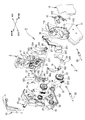
- the release motor 22 is in the housing so that its case (yoke) 22a is lower than the striker approach line X, and the output shaft 22b pivotally supported by the case 22a is directed rearward and downward.
- the authorized user who has been placed and holds the electronic key approaches the vehicle V within a predetermined area, and ID signal verification is performed by wireless communication performed between the electronic key and the receiver mounted on the vehicle V
- ID signal verification is performed by wireless communication performed between the electronic key and the receiver mounted on the vehicle V
- the user touches or approaches the detection switch SW, and the detection switch SW is turned on to drive the vehicle.
- the release motor 22 since the release motor 22 is disposed below the striker entry line X, there is a risk that the rainwater entering from the striker entry groove 41 may adhere to the release motor 22, but the release motor 22 has an output Since the shaft 22b is arranged to be directed obliquely downward to the rear, it is possible to minimize rainwater infiltration into the case 22a.
- the release worm wheel 23 has a disk shape and is pivotally supported within the housing by a shaft 31 facing inward and outward directions and fixed to an output shaft 22b pivotally supported by the case 22a of the release motor 22.
- the set position (for example, the position shown in FIG. 7) against the biasing force of the spring 35 (see FIG. 5) wound around the shaft 31 by meshing with the worm 221 and driving the release motor 22.
- the release motor 22 stops rotating by a predetermined angle in a clockwise direction from the position shown in FIG. 9 to a position shown in FIG.
- the release worm wheel 23 is provided with an involute curved cam surface 231 in which the distance from the rotation center to the outer peripheral surface is gradually increased in the counterclockwise direction in FIG. 7, for example.
- the shaft 31 for pivotally supporting the release worm wheel 23 is disposed below the case 22a of the release motor 22 and behind the output shaft 22b.
- the electric release lever 24 is in the housing and is pivotally supported at its central portion in the front-rear direction by the shaft 102 (release shaft) and extends forward and the tip end slides on the cam surface 231 of the release worm wheel 23 A possible first arm portion 241 and a second arm portion 242 which extends rearward and whose tip end portion can come in contact with the released portion 71 of the open lever 7 from the lower side.
- the shaft 102 that is, the rotation center of the electric release lever 24 is an open lever 7 in the housing below the upper half of the case 22a of the release motor 22 and the striker approach line X and behind the shaft 31. Placed in front of the
- the tip of the first arm portion 241 of the electric release lever 24 abuts on the small diameter portion of the cam surface 231 in the release worm wheel 23
- the electric release lever 24 is held in the set position shown in FIG.
- the release worm wheel 23 rotates clockwise from the set position shown in FIG. 7 by a predetermined angle based on the drive of the release motor 22 and pivots to the release position shown in FIG.
- the distal end portion of the first arm portion 241 relatively slides on the cam surface 231 and is displaced to the large diameter portion of the cam surface 231, whereby the electric release lever 24 pivots to the release operation position shown in FIG.
- the distal end of the second arm portion 242 abuts against the released portion 71 of the open lever 7 from below to release the open lever 7 and release the engagement relationship between the latch 5 and the ratchet 6.
- the front door FD can be opened.
- the control unit ECU allows the authorized user carrying the electronic key to approach the vehicle V within a predetermined area, and the electronic key and the receiver mounted on the vehicle V If the ID signal matches in the wireless communication between them and the authorized user is authenticated as approaching the vehicle V, the detection switch is detected regardless of whether the locking and unlocking mechanism is in the unlocked state or the locked state.
- the detection of SW is enabled, and when the detection switch SW is touched or approached by the user to turn on the detection switch SW, the release motor 22 is drive-controlled to enable the front door FD to be opened. In this case, when the locking and unlocking mechanism is in the locked state, after the driving of the release motor 22 is finished, the locking and unlocking motor 14 is controlled to unlock and switch to the unlocked state.
- the positions of the respective elements constituting the basic structure of the operation mechanism are set as follows.
- the shaft 101 forming the rotation center of the lock lever 16 and the case 14 a of the locking and unlocking motor 14 are positioned above the striker approach line X.
- the shaft 102 serving as the rotation center of the electric release lever 24, the shaft 31 serving as the rotation center of the release worm wheel 23, and the case 22a of the release motor 22 are lower than the striker approach line X. As shown in FIG.
- a straight line contacting the axis 31 of the shaft 31 and extending backward is a straight line A
- a straight line contacting a top of the release worm wheel 23 and extending backward is a straight line B
- a straight line contacting the upper end of the release motor 22 and extending backward is a straight line D
- a straight line contacting a lower end of the release motor 22 and extending backward is a straight line E and the straight lines D and E
- the locking and unlocking mechanism and the electric release mechanism can be divided into upper and lower portions in the housing with the striker approach line X as a boundary, the elements are arranged neatly in the housing
- the release motor 22, the release worm wheel 23, and the electric release lever 24 can be arranged in the front-rear direction by positioning the shaft 102 in the above-described position, and the downward protrusion is minimized. It is possible to reduce the size of the housing, and hence the size of the door latch device 1F.
- the control unit ECU authenticates that the authorized user carrying the electronic key approaches the vehicle V
- the control is performed when the authorized user touches or approaches the detection switch SW.
- the device ECU drives and controls the release motor 22 so as to rotate the release worm wheel 23 from the set position to the release direction (clockwise in FIG. 7).
- the tip of the first arm portion 241 slides on the cam surface 231 of the release worm wheel 23 to move from the set position shown in FIG.
- the distal end portion of the second arm portion 242 abuts against the to-be-released portion 71 of the open lever 7 from below, and the open lever 7 is operated to release.
- the front door FD can be opened by releasing the meshing state of the meshing mechanism.
- the unlocking is performed.
- the release motor 22 can be driven and controlled to release the electric release lever 24 to open the front door FD, as shown in FIG.
- the locking and unlocking motor 14 is controlled to drive. Switch to the unlocked state.
- a passenger who does not possess an electronic key can open the front door FD by opening the outside handle OH of the front door FD only when the front door FD is in the unlocked state. .
- the door opening operation is transmitted to the outside lever 21 via the unillustrated connecting member, and the outside lever 21 is turned counterclockwise in FIG. Release is activated.
- the open link 18 connected to the connection portion 211 of the outside lever 21 is released upward from the set position shown in FIG. 7, and the release portion 184 becomes the released portion 71 of the open lever 7 by the release operation. It abuts from below and releases the open lever 7.
- the ratchet 6 can be disengaged from the full latch engagement portion 51 of the latch 5 to open the front door FD.
- the open link 18 is moved upward from the set position along with the release operation of the outside lever 21 based on the door opening operation of the outside handle OH. Even when the release operation is performed, the release portion 184 of the open link 18 moves so as to cross the front of the released portion 71 of the open lever 7 and does not abut against the released portion 91. The lever 7 can not be released and the front door FD can not be opened. Therefore, in the locked state, the passenger and other users who do not have the electronic key can not open the front door FD from the outside of the vehicle.
- the outside handle OH of the front door FD is for opening the emergency door when the release motor 22 can not be driven due to a failure or the like of the release motor 22 or an electrical system related to the release motor 22. It can also be used as an external mechanical operation element of However, when in the locked state, it is necessary to switch the locking and unlocking mechanism to the unlocked state by the power of the locking and unlocking motor 14 by the unlocking operation of the key cylinder KC and the unlocking operation of the operation switch provided on the electronic key. is there.
- the inside operation system of the specification 1 is configured by the inside lever 19 shown in FIGS.
- the inside lever 19 is in the housing, and a slightly lower central portion in the vertical direction is pivotally supported by the shaft 102 coaxial with the electric release lever 24 and extends upward and is a circle provided on the second cover 11 It has a first arm 191 projecting outward from an arc-shaped opening 113 (see FIG. 3) and a second arm 192 extending diagonally downward and backward, and the upper portion of the first arm 191 is configured by a Bowden cable or the like.
- the biasing force of the spring 34 wound around the shaft 102 is resisted, for example, as shown in FIG.
- the connecting member 33 passes between the case 14a of the locking / unlocking motor 14 disposed at the upper portion in the housing and the case 22a of the release motor 22 similarly disposed at the lower portion, so that the first lever of the inside lever 19 is engaged. It is connected to the top of the arm 191.
- the thickness of the housing in the inward direction can be reduced because the connecting member 33 does not overlap in the inward / outward direction with the cases 14a and 22a having a large thickness in the inward / outward direction.
- the open operation is transmitted to the inside lever 19 via the connecting member 33.
- the inside lever 19 performs release operation so as to turn a predetermined angle in the counterclockwise direction around the axis 102 coaxial with the electric release lever 24, and as shown in FIG. 11, the contact portion 192a of the first arm portion 192 is opened.
- the open link 18 is released upward by coming into contact with the pivoting portion 181 of the link 18 from below.
- the release portion 184 abuts from the lower side of the release portion 71 of the open lever 7 by the release operation, rotates the open lever 7 in the release direction to release the meshing of the meshing mechanism, and the front door FD Allow opening.
- the lock motor 14 is driven by the unlock operation of the lock knob provided in the vehicle or the operation of the operation switch provided in the vehicle. It is necessary to open the inside handle IH after switching to the unlocked state, for example.
- the door latch device 1F of specification 1 first switches the locking / unlocking mechanism to the unlocked state, and then opens the inside handle IH of the front door FD to operate the inside lever
- the release operation 19 is set to be able to open the front door FD.
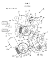
- the inside operation system of specification 2 is constituted by an inside lever 19A shown in FIGS.
- the inside lever 19A is pivotally supported by an axis 102 coaxial with the electric release lever 24, and forms an unlocking portion 193 not formed on the inside lever 19 of the specification 1.
- the unlocking action portion 193 is formed at the upper end portion of the first arm portion 191, and has a shape capable of coming into contact with the lower portion 173 of the connection arm portion 171 of the knob lever 17.
- the inside lever 19A is released from the set position shown in FIG. 13 against the biasing force of the spring 34 based on the first door opening operation of the inside handle IH (the reverse operation in FIG. When it rotates clockwise, as shown in FIG. 14, the lock lever 16 and the open link 18 are moved from the lock position to the unlock position via the knob lever 17 by abutting on a part 173 of the knob lever 17. .
- the open link 18 is unlocked together with the lock lever 16 in combination with the upward movement in the idle state crossing the front of the to-be-released portion 71 of the open lever 7 along with the release operation of the inside lever 19A.
- the open link 18 is unlocked because a part of the open link 18 abuts against the part of the open lever 7 from the direction in which the open lever 7 can not rotate. A pause condition occurs that stops before the position.
- the door latch device 1F of specification 2 when the door latch device 1F of specification 2 is in the locked state, it switches to the unlocked state by the first door opening operation of the inside handle IH, and releases the meshing mechanism by the second door opening operation of the inside handle IH. And the front door FD can be opened.
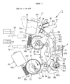
- the inside operation system of specification 3 is configured by an inside lever 19B shown in FIGS.
- the inside lever 19B is pivotally supported by a shaft 102 coaxial with the electric release lever 24 and is not formed on the inside lever 19 of the specification 1 and has an unlocking portion 193 (the same as the specification 2) and an electric release portion 194 is formed, and the second arm portion 192 formed in the specification 1 is not formed.
- the unlocking action portion 193 is the same as that of the specification 2 and is formed at the upper end portion of the first arm portion 191 and can abut against a portion 173 which is the lower portion of the connection arm portion 171 of the knob lever 17 It has a shape.
- the electric release action portion 194 makes the second arm portion 242 of the electric release lever 24 release. By abutting from the counterclockwise direction, the electric release lever 24 is shaped to be released.
- the inside lever 19B In the unlocked state shown in FIG. 15, when the inside handle IH is operated to open the door, the inside lever 19B is rotated about the shaft 102 by a predetermined angle in the counterclockwise direction from the set position.
- the actuating portion 194 abuts against the second arm portion 242 of the electric release lever 24 in the counterclockwise direction, whereby the electric release lever 24 performs the release operation in the counterclockwise direction centering on the shaft 102 from the set position shown in FIG.
- the front end portion of the second arm portion 242 abuts on the to-be-released portion 71 of the open lever 7 from below to release the meshing of the meshing mechanism and open the front door FD.
- the door latch device 1F of specification 3 switches the locking / unlocking mechanism to the unlocked state and releases the meshing of the meshing mechanism by one opening operation of the inside handle IH. Is set so that the front door FD can be opened.
- the specification 4 is set to the door latch device 1R for the rear door, and as shown in FIGS. 18 to 21, in addition to the first inside lever 19C and the second inside lever 19D of the inside operation system, a childproof operation lever A child proof mechanism is provided having 19E and connect link 19F.
- the first and second inside levers 19C and 19D are respectively pivoted on an axis 102 coaxial with the electric release lever 24.
- the upper end portion of a first arm portion 191 (corresponding to the first arm portion 191 of the inside lever 19 in specification 1) extending upward is connected to the inside handle IH of the rear door RD via a connecting member 33
- the release operation is performed counterclockwise from the set position shown in FIG. 19 based on the door opening operation of the inside handle IH.
- the first inside lever 19C is provided with a control hole 195 substantially L-shaped in a side view.
- a portion corresponding to the second arm portion 192 set to the specification 1 is not provided.
- the second inside lever 19D is a long hole 196 in the vertical direction overlapping a part of the control hole 195 of the first inside lever 19C, and a second arm 192 extending obliquely downward (a second arm of the inside lever 19 of the specification 1 And the like).
- the child proof operating lever 19E is pivotally supported by the shaft 103 in the housing and is in the child unlock position shown in FIG. 19 and the child lock position shown in FIG. 21 rotated counterclockwise from the child unlock position by a predetermined angle. It can rotate.
- An arc hole 197 facing in the front-rear direction is provided at the front of the childproof operating lever 19E, and an operation part 198 projecting outward from the rear end face of the rear door RD is also provided at the rear.
- an elongated hole 19Fa provided at the central portion in the vertical direction is slidably engaged with the shaft 102 in the vertical direction, and a lower projection 19Fb provided at the lower portion slides in an arc hole 197 of the childproof operation lever 19E.
- the childproof operating lever 19E is in the child unlock position shown in FIG. 19 by the movable engagement and the upper projection 19Fc provided at the upper portion being slidably engaged with the control hole 195 and the long hole 196, respectively.
- the upper projection 19Fc engages with the narrow upper portion of the control hole 195 to transmit the release operation of the first inside lever 19C to the second inside lever 19D, and the childproof operation lever 19E When in the child lock position shown in FIG. The release operation of the side lever 19C is impossible transmitted to the second inside lever 19D.
- child unlocking state a state in which the operation of the first inside lever 19C can be transmitted to the second inside lever 19D when the childproof operating lever 19E is in the child unlocking position
- the “child lock state” refers to a state in which the operation of the first inside lever 19C can not be transmitted to the second inside lever 19D when the childproof operating lever 19E is in the child lock position.
- the first inside lever 19C when the inside handle IH is door-opened with the locking / unlocking mechanism in the unlocked state and the child proof mechanism in the child unlocked state, as shown in FIG. 20, the first inside lever 19C. Is pivoted from the set position counterclockwise about the shaft 102 by a predetermined angle. The rotation is transmitted to the second inside lever 19D via the connect link 19F, and the second inside lever 19D performs release operation in the counterclockwise direction together with the first inside lever 19C. As a result, the contact portion 192a of the second arm portion 192 of the second inside lever 19D contacts the lower portion of the pivoting portion 181 of the open link 18 from below to release the open link 18 upward. In the open link 18, the release portion 184 abuts from the lower side of the release portion 71 of the open lever 7 by the release operation, rotates the open lever 7 in the release direction, releases the meshing mechanism, and opens the rear door RD. Make it possible.
- the locking / unlocking mechanism When the locking / unlocking mechanism is in the locked state and the child proof mechanism is in the child unlocked state, the first inside lever 19C and the second inside lever 19D are released based on the door opening operation of the inside handle IH, and the open link 18 Even when release operation is performed upward from the set position, the release portion 184 of the open link 18 is in an idle state in which it does not abut against the released portion 71 of the open lever 7 as in the specification 1, so the rear door RD is opened. It is not possible. Therefore, in this state, as in specification 1, in order to open the rear door RD by the door open operation of the inside handle IH, the unlocking operation of the lock knob provided in the vehicle or the operation is performed by the operation switch provided in the vehicle. After switching the locking / unlocking mechanism to the unlocked state by driving the lock motor 14 or the like, it is necessary to perform the door open operation of the inside handle IH.
- the inside handle IH of the rear door RD is door-opened and the first inside lever 19C is released. Since the release operation is not transmitted to the second inside lever 19D, the rear door RD can not be opened. Therefore, in this state, although the rear door RD can be opened from the outside of the vehicle, the rear door RD can not be opened from the inside of the vehicle.
- the specification 5 is set to the door latch device 1R for the rear door, and as shown in FIGS. 22 to 24, in addition to the first inside lever 19G and the second inside lever 19D of the inside operation system, A childproof mechanism having a childproof operating lever 19E and a connect link 19F is provided.
- the first inside lever 19G is pivotally supported by the shaft 102 coaxial with the electric release lever 24, and the upper end of the first arm 191 extending upward is connected to the inside handle IH of the rear door RD via the connecting member 33.
- the release operation is performed counterclockwise from the set position shown in FIG. 22 based on the door opening operation of the inside handle IH.
- the first inside lever 19G is provided with a control hole 195 having a substantially L-shaped side view in the same shape as that of the specification 4 and an unlocking portion 193 similar to that set to the specifications 2 and 3.
- the second inside lever 19D, the child proof operating lever 19E, and the connect link 19F are the same as those of the specification 4 described above, so the same reference numerals as those of the specification 4 are given to FIGS.
- the first inside lever 19G and the second inside lever 19D both release and the specification
- the unlocking portion 193 of the first inside lever 19G is one of the knob levers 17 as shown in FIG. 23 based on the release operation of the first inside lever 19G by the first opening operation of the inside handle IH. Switch to the unlocked state by touching the part 173, and release the meshing of the meshing mechanism via the open link 18 based on the release operation of the second inside lever 19D by the second door opening operation of the inside handle IH.
- the rear door RD can be opened.
- the inside handle IH of the rear door RD is opened regardless of whether the locking / unlocking mechanism is in the unlocked state or the locked state. Even though the rear door RD can not be opened, when the locking / unlocking mechanism is in the locked state, the door can be switched to the unlocked state by the opening operation of the inside handle IH of the rear door RD.
- the position of the shaft 102 for pivotally supporting the electric release lever 24 in the housing is within the range C described above and behind the release worm wheel 23 and below the lock lever 16.
- the open lever 18 and the open lever 7, and the rotary shafts of the inside levers 19, 19A, 19B, 19C, 19D and 19G of the respective specifications are coaxial with the electric release lever 24 in the operation mechanism.
- the electric release lever 24 can operate each element as follows without changing the position of each element constituting the basic structure for each specification.
- the electric release lever 24 can operate the open lever 7 directly.
- the inside lever 19 can directly operate the open link 18.
- the inside lever 19A can directly operate the open link 18 and the lock lever 16.
- the inside lever 19B can directly operate the lock lever 16 and the electric release lever 24.
- the second inside lever 19D in the configuration in which the first inside lever 19C and the second inside lever 19D are divided, the second inside lever 19D can directly operate the open link 18.
- the first inside lever 19G is the lock lever 16
- the second inside lever 19D is the open link 18, in the configuration 5 in which the first inside lever 19G and the second inside lever 19D are divided. It can be operated directly.
- the basic structure of the operating mechanism can be shared among the specifications.
- the release motor 22, the release worm wheel 23, the electric release lever 24, and the inside lever 19 (19A, 19B, 19C, 19D, 19G) can be orderly arranged in the front-rear direction, so that the housing can be miniaturized and hence the door latch.
- the device 1F can be miniaturized.
Abstract
Description
第1の発明は、ボディ及び当該ボディに収容されストライカと噛合可能な噛合機構を含む噛合ユニットと、前記噛合機構を操作可能な操作機構及び前記ボディに固定され前記操作機構を収容するためのハウジングを含む操作ユニットを備え、前記操作機構は、施解錠用モータと、前記施解錠用モータの駆動に基づいて回動可能な施解錠用回動体と、前記施解錠用回動体の回動に基づいて、車外側の外部機械的操作要素のドア開操作を有効にするアンロック状態及び不能にするロック状態に選択的に切り替え可能な機械的要素により構成される施解錠機構と、前記施解錠用モータよりも下位に配置されるリリース用モータと、前記ハウジングにリリース軸により枢支され、前記リリース用モータの駆動に基づいて回動し、前記施解錠機構の状態に関係なく前記噛合機構の噛合を解除可能な電動リリースレバーとを備え、前記ストライカが前記ボディに設けたストライカ進入溝に対して進入し前記噛合機構に噛合する際の進入路線をストライカ進入線Xとしたとき、前記施解錠用モータを、自体のケースが前記ストライカ進入線Xよりも上位になるように配置し、前記リリース用モータを、自体のケースが前記ストライカ進入線Xよりも下位になるように配置したことを特徴とする。
図1に示すように、4ドアタイプの自動車VのフロントドアFDには、フロントドアFDを閉鎖位置に保持するためのフロントドア用のドアラッチ装置1Fと、車外側に設けられる外部機械的操作要素のアウトサイドハンドルOH及び電気的検出要素の検出スイッチSWと、車内側に設けられる内部機械的操作要素のインサイドハンドルIHと、車外から後述の施解錠機構をロック状態及びアンロック状態に選択的に切り替え操作するためのキーシリンダKCと、車内から施解錠機構をロック状態及びアンロック状態に選択的に切り替え操作するためのロックノブ(図示省略)とが配置される。なお、ドアラッチ装置1Fには、後述の仕様1~3のうちいずれかの仕様が設定される。
次に、ドアラッチ装置1F、1Rの基本構造について説明する。
なお、ドアラッチ装置1F及び1Rの基本構造は、一部(後述のインサイド操作系の要素を含む)を除いて互いに同一であるため、以下の基本構造及びそれに係わる動作の説明においては、仕様1のドアラッチ装置1Fについて説明し、ドアラッチ装置1Rについては、特に説明がない限り、「ドアラッチ装置1F」を「ドアラッチ装置1R」、また「フロントドアFD」を「リヤドアRD」とそれぞれ置き換えて解釈するものとする。また、各仕様の説明については、各仕様共通の基本構造及びそれに係わる動作を説明したあとに説明する。
なお、インサイド操作系の要素は、インサイドハンドルハンドルIHのドア開操作に連係するレバー、リンク等の指す。これについては、あとで詳述する。
なお、以下の説明で使用する方位は、ドアラッチ装置1F、1Rを各ドアFD、RDに取り付けた状態を指す。
操作ユニット3は、ボディ4の前面を覆うようにボディ4に固定される平面視略L字状の合成樹脂製の第1カバー10と、当該第1カバー10の車内側を向く側面を閉鎖する合成樹脂製の第2カバー11と、当該第2カバー11の略上半部の側面を車内側から閉鎖する合成樹脂製のウォータープルーフサイドカバー12と、第1カバー10と第2カバー11との上部合わせ面を覆うウォータプルーフトップカバー13と、ハウジング内に収容される操作機構(符号無し)とを有する。
また、以下の説明で使用する「アンロック状態」とは、ロックレバー16、ノブレバー17及びオープンリンク18がそれぞれアンロック位置にある状態を指し、また、「ロック状態」とは、ロックレバー16、ノブレバー17及びオープンリンク18がそれぞれロック位置にある状態を指す。なお、施解錠機構の構成は、本実施形態に限定されるものでなく、例えば、ノブレバー17を省略して、ロックレバー16をロックノブに連係しても良い。
このように、施解錠用モータ14を、ケース14aがストライカ進入線Xよりも上位になるようにハウジング内に配置することによって、ストライカ進入溝41から浸入した雨水がケース14a内に浸入することを防止する。
・ロックレバー16の回転中心をなす軸101及び施解錠用モータ14のケース14aを、ストライカ進入線Xよりも上位とする。
・電動リリースレバー24の回転中心をなす軸102、リリース用ウォームホイール23の回転中心をなす軸31及びリリース用モータ22のケース22aを、ストライカ進入線Xよりも下位とする。
・図7に示すように、軸31の軸心と接し後方へ延伸する直線を直線Aとし、リリース用ウォームホイール23の最上部と接し後方へ延伸する直線を直線Bとし、直線Aと直線Bとの間の範囲Cとし、リリース用モータ22の上端と接し後方へ延伸する直線を直線Dとし、リリース用モータ22の下端と接し後方へ延伸する直線を直線Eとし、直線Dと直線Eとの間の範囲を範囲Fとしたとき、リリース用ウォームホイール23を範囲F内とし、軸102を、範囲C内にあって、かつリリース用ウォームホイール23よりも後位で、オープンリンク18及びオープンレバー7よりも前位とする。
次に、ドアラッチ装置1Fの基本動作について説明する。
フロントドアFDが全閉状態にあって、施解錠機構がアンロック状態にある場合には、操作機構の各要素は、図7に示す位置に保持されている。
フロントドアFDが全閉状態にあって、施解錠機構がロック状態にある場合には、操作機構の各要素は、図8に示す位置に保持されている。
フロントドアFDが全閉状態にあって、施解錠機構がアンロック状態又はロック状態の何れの状態にあっても、電子キーを所持していない同乗者が操作スイッチSWを操作しても、制御装置ECUが正規の使用者であると認証しないため、リリース用モータ22を駆動させることはできない。
次に、各仕様におけるインサイド操作系の構造及び動作について説明する。
仕様1のインサイド操作系は、図7~11に示すインサイドレバー19によって構成される。インサイドレバー19は、ハウジング内にあって、上下方向における中央部の若干下部が電動リリースレバー24と同軸の軸102により枢支されると共に、上方へ延伸して第2カバー11に設けられた円弧状の開口113(図3参照)から外側に突出する第1アーム部191と、斜め後下方へ延伸する第2アーム部192とを有し、第1アーム部191の上部がボーデンケーブル等により構成される連結部材33を介してインサイドハンドルIHに連結されることによって、インサイドハンドルIHのドア開操作に基づいて、軸102周りに巻装されたスプリング34の付勢力に抗して、例えば図7に示すセット位置から反時計方向へ所定角度回動し、図11に示すようにリリース作動する。第2アーム部192の先端部には、インサイドハンドレバー19がリリース作動した際、オープンリンク18の回動部181に対して下方から当接可能な当接部192aが形成される。
仕様2のインサイド操作系は、図12~14に示すインサイドレバー19Aによって構成される。インサイドレバー19Aは、電動リリースレバー24と同軸の軸102に枢支されると共に、仕様1のインサイドレバー19には形成されていないアンロック作用部193を形成する。
仕様3のインサイド操作系は、図15~17に示すインサイドレバー19Bによって構成される。インサイドレバー19Bは、電動リリースレバー24と同軸の軸102に枢支されると共に、仕様1のインサイドレバー19には形成されていないアンロック作用部193(仕様2と同じもの)及び電動リリース作用部194を形成し、かつ仕様1に形成されていた第2アーム部192を形成しない。
仕様4は、リヤドア用のドアラッチ装置1Rに設定されるものであって、図18~21に示すように、インサイド操作系の第1インサイドレバー19C及び第2インサイドレバー19Dに加え、チャイルドプルーフ操作レバー19E及びコネクトリンク19Fを有するチャイルドプルーフ機構が設けられる。
図19に示すように、施解錠機構がアンロック状態で、かつチャイルドプルーフ機構がチャイルドアンロック状態において、インサイドハンドルIHがドア開操作されると、図20に示すように、第1インサイドレバー19Cは軸102を中心にセット位置から反時計方向へ所定角度回動する。当該回動は、コネクトリンク19Fを介して第2インサイドレバー19Dに伝達され、第2インサイドレバー19Dは、第1インサイドレバー19Cと共に反時計方向へリリース作動する。これにより、第2インサイドレバー19Dの第2アーム部192の当接部192aがオープンリンク18の回動部181の下部に下方から当接して、オープンリンク18を上方へリリース作動させる。オープンリンク18は、リリース作動により解除部184がオープンレバー7の被解除部71に下方から当接して、オープンレバー7をリリース方向へ回動させて噛合機構の噛合を解除し、リヤドアRDを開きを可能にする。
仕様5は、リヤドア用のドアラッチ装置1Rに設定されるものであって、図22~24に示すように、インサイド操作系の第1インサイドレバー19G及び第2インサイドレバー19Dに加え、仕様4と同様のチャイルドプルーフ操作レバー19E及びコネクトリンク19Fを有するチャイルドプルーフ機構が設けられる。
図22に示すように、施解錠機構がアンロック状態で、かつチャイルドプルーフ機構がチャイルドアンロック状態において、インサイドハンドルIHがドア開操作された場合には、第1インサイドレバー19G及び第2インサイドレバー19Dが共にリリース作動するため、仕様4と同様に、オープンリンク18を介して噛合機構の噛合を解除してリヤドアRDを開くことができる。
・仕様1において、インサイドレバー19は、オープンリンク18を直接作動させることができる。
・仕様2において、インサイドレバー19Aは、オープンリンク18及びロックレバー16を直接作動させることができる。
・仕様3において、インサイドレバー19Bは、ロックレバー16及び電動リリースレバー24を直接作動させることができる。
・仕様4において、第1インサイドレバー19Cと第2インサイドレバー19Dとが分割された構成にあって、第2インサイドレバー19Dは、オープンリンク18を直接作動させることができる。
・仕様5において、第1インサイドレバー19Gと第2インサイドレバー19Dとが分割された構成にあって、第1インサイドレバー19Gは、ロックレバー16、また第2インサイドレバー19Dは、オープンリンク18をそれぞれ直接作動させることができる。
3 操作ユニット 4 ボディ
5 ラッチ(噛合機構) 6 ラチェット(噛合機構)
6a 下端部 7 オープンレバー
8 ラッチ軸 9 ラチェット軸
10 第1カバー 11 第2カバー
12 ウォータープルーフサイドカバー 13 ウォータープルーフトップカバー
14 施解錠用モータ 14a ケース
14b 出力軸
15 施解錠用ウォームホイール(施解錠用回動体)
16 ロックレバー(施解錠機構) 17 ノブレバー(施解錠機構)
18 オープンリンク(施解錠機構)
19、19A、19B インサイドレバー
19C、19G 第1インサイドレバー 19D 第2インサイドレバー
19E チャイルドプルーフ操作レバー 19F コネクトリンク
19Fa 長孔 19Fb 下突部
19Fc 上突部 20 キーレバー
21 アウトサイドレバー 22 リリース用モータ
22a ケース 22b 出力軸
23 リリース用ウォームホイール(リリース用回動体)
24 電動リリースレバー 25 配線プレート
26 軸 27 スプリング
28 連結部材 29 保持部材
30 検出スイッチ 31 軸
33 連結部材 34 スプリング
35 スプリング 36 トーションスプリング
37 イナーシャレバー 37a 上端部
38 スプリング 41 ストライカ進入溝
51 フルラッチ係合部 52 ハーフラッチ係合部
53 噛合溝 71 被解除部
101、102 軸(リリース軸) 111 軸
112 円弧孔 113 開口
141 ウォーム 151 歯部
161 歯部 162 連結突部
163 カム面 164 アーム部
171 連結アーム部 172 連結孔
173 一部 165 案内壁
181 回動部 182 連結孔
183 連結突部 184 解除部
191 第1アーム部 192 第2アーム部
192a 当接部 193 アンロック作用部
194 電動リリース作用部 195 制御孔
196 長孔 197 円弧孔
198 操作部 211、212 連結部
221 ウォーム 231 カム面
241 第1アーム部 242 第2アーム部
251 カプラー 371 突部
ECU 制御装置 FD フロントドア
IH インサイドハンドル(内部機械的操作要素)
KC キーシリンダ
OH アウトサイドハンドル(外部機械的操作要素)
RD リヤドア S ストライカ
SW 検出スイッチ(電気的検出要素) X ストライカ進入線
V 自動車
Claims (3)
- ボディ及び当該ボディに収容されストライカと噛合可能な噛合機構を含む噛合ユニットと、前記噛合機構を操作可能な操作機構及び前記ボディに固定され前記操作機構を収容するためのハウジングを含む操作ユニットを備え、
前記操作機構は、
施解錠用モータと、
前記施解錠用モータの駆動に基づいて回動可能な施解錠用回動体と、
前記施解錠用回動体の回動に基づいて、車外側の外部機械的操作要素のドア開操作を有効にするアンロック状態及び不能にするロック状態に選択的に切り替え可能な機械的要素により構成される施解錠機構と、
前記施解錠用モータよりも下位に配置されるリリース用モータと、
前記ハウジングにリリース軸により枢支され、前記リリース用モータの駆動に基づいて回動し、前記施解錠機構の状態に関係なく前記噛合機構の噛合を解除可能な電動リリースレバーとを備え、
前記ストライカが前記ボディに設けたストライカ進入溝に対して進入し前記噛合機構に噛合する際の進入路線をストライカ進入線Xとしたとき、
前記施解錠用モータを、自体のケースが前記ストライカ進入線Xよりも上位になるように配置し、
前記リリース用モータを、自体のケースが前記ストライカ進入線Xよりも下位になるように配置したことを特徴とする自動車用ドアラッチ装置。 - 前記リリース用モータの上端と接し後方へ延伸する直線を直線Dとし、前記リリース用モータの下端と接し後方へ延伸する直線を直線Eとし、直線Dと直線Eとの間の範囲を範囲Fとしたとき、
前記リリース軸を、前記範囲F内に配置したことを特徴とする請求項1記載の自動車用ドアラッチ装置。 - 前記リリース用モータを、自体の前記ケースに枢支された出力軸が下方へ向くように配置したことを特徴とする請求項1又は2記載の自動車用ドアラッチ装置。
Priority Applications (6)
| Application Number | Priority Date | Filing Date | Title |
|---|---|---|---|
| BR112017017309-3A BR112017017309A2 (ja) | 2015-02-17 | 2015-02-17 | A door latch device for cars |
| PCT/JP2015/054348 WO2016132463A1 (ja) | 2015-02-17 | 2015-02-17 | 自動車用ドアラッチ装置 |
| CN201580076284.5A CN107250475B (zh) | 2015-02-17 | 2015-02-17 | 机动车用门闩装置 |
| PL15882567T PL3260635T3 (pl) | 2015-02-17 | 2015-02-17 | Urządzenie do ryglowania drzwi samochodowych |
| EP15882567.9A EP3260635B1 (en) | 2015-02-17 | 2015-02-17 | Automobile door latch apparatus |
| US15/549,615 US11035156B2 (en) | 2015-02-17 | 2015-02-17 | Automobile door latch apparatus |
Applications Claiming Priority (1)
| Application Number | Priority Date | Filing Date | Title |
|---|---|---|---|
| PCT/JP2015/054348 WO2016132463A1 (ja) | 2015-02-17 | 2015-02-17 | 自動車用ドアラッチ装置 |
Publications (1)
| Publication Number | Publication Date |
|---|---|
| WO2016132463A1 true WO2016132463A1 (ja) | 2016-08-25 |
Family
ID=56688867
Family Applications (1)
| Application Number | Title | Priority Date | Filing Date |
|---|---|---|---|
| PCT/JP2015/054348 WO2016132463A1 (ja) | 2015-02-17 | 2015-02-17 | 自動車用ドアラッチ装置 |
Country Status (6)
| Country | Link |
|---|---|
| US (1) | US11035156B2 (ja) |
| EP (1) | EP3260635B1 (ja) |
| CN (1) | CN107250475B (ja) |
| BR (1) | BR112017017309A2 (ja) |
| PL (1) | PL3260635T3 (ja) |
| WO (1) | WO2016132463A1 (ja) |
Cited By (1)
| Publication number | Priority date | Publication date | Assignee | Title |
|---|---|---|---|---|
| US20210363790A1 (en) * | 2020-05-22 | 2021-11-25 | Shiroki Corporation | Lock device |
Families Citing this family (7)
| Publication number | Priority date | Publication date | Assignee | Title |
|---|---|---|---|---|
| CN107687292B (zh) * | 2016-08-03 | 2020-10-27 | 山东新北洋信息技术股份有限公司 | 电子锁控制方法及控制装置 |
| JP6884094B2 (ja) | 2017-12-25 | 2021-06-09 | 三井金属アクト株式会社 | 車両ドアラッチ装置 |
| US11608664B2 (en) * | 2017-12-25 | 2023-03-21 | Mitsui Kinzoku Act Corporation | Vehicle door latch apparatus |
| US11280116B2 (en) * | 2018-05-15 | 2022-03-22 | Magna Closures Inc. | Closure latch assembly with child lock having asymmetrical toggle spring arrangement |
| KR102633868B1 (ko) * | 2019-07-26 | 2024-02-05 | 현대자동차 주식회사 | 차량용 전동식 도어 래치 |
| CN114502811B (zh) * | 2019-10-09 | 2023-11-28 | 索斯科公司 | 电子致动和锁定的手套箱系统 |
| WO2022245866A1 (en) * | 2021-05-17 | 2022-11-24 | Motown Engineering, Inc. | Vehicle door latch |
Citations (4)
| Publication number | Priority date | Publication date | Assignee | Title |
|---|---|---|---|---|
| JPH05287951A (ja) * | 1992-04-08 | 1993-11-02 | Mitsui Mining & Smelting Co Ltd | スーパーロック機構付車両ドアロック装置 |
| JP2007009625A (ja) * | 2005-07-04 | 2007-01-18 | Nissan Motor Co Ltd | 車両用ドアロック装置およびドアロック方法 |
| JP2014118693A (ja) * | 2012-12-13 | 2014-06-30 | Tokai Rika Co Ltd | ロック装置 |
| JP2014214501A (ja) * | 2013-04-25 | 2014-11-17 | 株式会社ホンダロック | 車両用ドアのラッチ制御装置 |
Family Cites Families (18)
| Publication number | Priority date | Publication date | Assignee | Title |
|---|---|---|---|---|
| JP3758929B2 (ja) | 2000-03-17 | 2006-03-22 | アイシン精機株式会社 | 自動車用ドアロック装置 |
| EP1146186B1 (de) | 2000-04-14 | 2005-03-09 | Brose Schliesssysteme GmbH & Co. KG | Kraftfahrzeugschloss mit Öffnungsantrieb |
| US6733052B2 (en) * | 2000-12-14 | 2004-05-11 | Delphi Technologies, Inc. | Power operated vehicle door latch |
| JP4617588B2 (ja) | 2001-03-28 | 2011-01-26 | アイシン精機株式会社 | 車両用ドアラッチ操作装置 |
| JP4145774B2 (ja) | 2003-11-18 | 2008-09-03 | 三井金属鉱業株式会社 | ドア開閉装置 |
| DE202006012091U1 (de) * | 2006-08-04 | 2007-12-20 | BROSE SCHLIEßSYSTEME GMBH & CO. KG | Kraftfahrzeugschloß |
| JP4503051B2 (ja) * | 2007-07-23 | 2010-07-14 | 三井金属鉱業株式会社 | ドアロック装置 |
| JP4775345B2 (ja) * | 2007-08-24 | 2011-09-21 | アイシン精機株式会社 | 車両用ドアロック装置 |
| JP4905716B2 (ja) * | 2007-09-19 | 2012-03-28 | 三井金属アクト株式会社 | 自動車用ドアラッチ装置 |
| JP4918915B2 (ja) * | 2008-01-10 | 2012-04-18 | アイシン精機株式会社 | 車両用ドアロック装置 |
| JP4922202B2 (ja) * | 2008-01-31 | 2012-04-25 | 株式会社アルファ | 車両用ドアロック装置 |
| JP4618318B2 (ja) * | 2008-04-18 | 2011-01-26 | アイシン精機株式会社 | 車両用ドアロック装置 |
| US8474888B2 (en) * | 2009-03-25 | 2013-07-02 | Magna Closures Inc. | Closure latch for vehicle door |
| JP5627388B2 (ja) * | 2010-10-20 | 2014-11-19 | 株式会社ユーシン | ドアロック装置 |
| DE202012001960U1 (de) * | 2012-02-28 | 2013-05-29 | Kiekert Aktiengesellschaft | Kraftfahrzeugtürverschluss |
| EP2806091B1 (en) * | 2012-04-17 | 2017-10-04 | Magna Closures SpA | An electrical vehicle latch |
| JP5736611B2 (ja) * | 2012-09-13 | 2015-06-17 | 三井金属アクト株式会社 | 車両用ドアラッチシステム |
| DE112013005663T5 (de) | 2012-11-27 | 2015-09-03 | Magna Closures Inc. | Schloss für eine Fahrzeugtür |
-
2015
- 2015-02-17 WO PCT/JP2015/054348 patent/WO2016132463A1/ja active Application Filing
- 2015-02-17 EP EP15882567.9A patent/EP3260635B1/en active Active
- 2015-02-17 US US15/549,615 patent/US11035156B2/en active Active
- 2015-02-17 CN CN201580076284.5A patent/CN107250475B/zh active Active
- 2015-02-17 BR BR112017017309-3A patent/BR112017017309A2/ja not_active Application Discontinuation
- 2015-02-17 PL PL15882567T patent/PL3260635T3/pl unknown
Patent Citations (4)
| Publication number | Priority date | Publication date | Assignee | Title |
|---|---|---|---|---|
| JPH05287951A (ja) * | 1992-04-08 | 1993-11-02 | Mitsui Mining & Smelting Co Ltd | スーパーロック機構付車両ドアロック装置 |
| JP2007009625A (ja) * | 2005-07-04 | 2007-01-18 | Nissan Motor Co Ltd | 車両用ドアロック装置およびドアロック方法 |
| JP2014118693A (ja) * | 2012-12-13 | 2014-06-30 | Tokai Rika Co Ltd | ロック装置 |
| JP2014214501A (ja) * | 2013-04-25 | 2014-11-17 | 株式会社ホンダロック | 車両用ドアのラッチ制御装置 |
Cited By (2)
| Publication number | Priority date | Publication date | Assignee | Title |
|---|---|---|---|---|
| US20210363790A1 (en) * | 2020-05-22 | 2021-11-25 | Shiroki Corporation | Lock device |
| US11512507B2 (en) * | 2020-05-22 | 2022-11-29 | Aisin Corporation | Lock device |
Also Published As
| Publication number | Publication date |
|---|---|
| PL3260635T3 (pl) | 2020-03-31 |
| CN107250475B (zh) | 2019-07-26 |
| EP3260635A1 (en) | 2017-12-27 |
| EP3260635B1 (en) | 2019-10-16 |
| EP3260635A4 (en) | 2018-10-24 |
| CN107250475A (zh) | 2017-10-13 |
| BR112017017309A2 (ja) | 2018-04-03 |
| US20180023326A1 (en) | 2018-01-25 |
| US11035156B2 (en) | 2021-06-15 |
Similar Documents
| Publication | Publication Date | Title |
|---|---|---|
| WO2016132464A1 (ja) | 自動車用ドアラッチ装置 | |
| WO2016132463A1 (ja) | 自動車用ドアラッチ装置 | |
| WO2017109852A1 (ja) | 自動車用ドアロック装置 | |
| WO2017098563A1 (ja) | 自動車用ドアロック装置 | |
| WO2017090160A1 (ja) | 自動車用ドアロック装置 | |
| JP6483353B2 (ja) | 車両用ドア開閉装置 | |
| JP6651710B2 (ja) | 自動車用ドアロック装置 | |
| JP6450979B2 (ja) | 自動車用ドアロック装置 | |
| JP5824755B2 (ja) | 自動車用ドアラッチ装置 | |
| JP6672564B2 (ja) | ドアロックシステム | |
| US10829965B2 (en) | Door latch device | |
| JP2014109110A (ja) | 車両用ドアラッチシステム | |
| JP6707062B2 (ja) | 自動車用ドアラッチ装置 | |
| JP7175181B2 (ja) | ドアラッチ装置 | |
| JP6060420B2 (ja) | 車両用ドア開閉装置 |
Legal Events
| Date | Code | Title | Description |
|---|---|---|---|
| 121 | Ep: the epo has been informed by wipo that ep was designated in this application |
Ref document number: 15882567 Country of ref document: EP Kind code of ref document: A1 |
|
| REEP | Request for entry into the european phase |
Ref document number: 2015882567 Country of ref document: EP |
|
| WWE | Wipo information: entry into national phase |
Ref document number: 15549615 Country of ref document: US |
|
| NENP | Non-entry into the national phase |
Ref country code: DE |
|
| REG | Reference to national code |
Ref country code: BR Ref legal event code: B01A Ref document number: 112017017309 Country of ref document: BR |
|
| ENP | Entry into the national phase |
Ref document number: 112017017309 Country of ref document: BR Kind code of ref document: A2 Effective date: 20170811 |