WO2016129459A1 - リチウムイオン二次電池用正極、リチウムイオン二次電池用電極、及びリチウムイオン二次電池 - Google Patents
リチウムイオン二次電池用正極、リチウムイオン二次電池用電極、及びリチウムイオン二次電池 Download PDFInfo
- Publication number
- WO2016129459A1 WO2016129459A1 PCT/JP2016/053094 JP2016053094W WO2016129459A1 WO 2016129459 A1 WO2016129459 A1 WO 2016129459A1 JP 2016053094 W JP2016053094 W JP 2016053094W WO 2016129459 A1 WO2016129459 A1 WO 2016129459A1
- Authority
- WO
- WIPO (PCT)
- Prior art keywords
- positive electrode
- active material
- lithium ion
- ion secondary
- electrode active
- Prior art date
- Legal status (The legal status is an assumption and is not a legal conclusion. Google has not performed a legal analysis and makes no representation as to the accuracy of the status listed.)
- Ceased
Links
Images

Classifications
-
- H—ELECTRICITY
- H01—ELECTRIC ELEMENTS
- H01M—PROCESSES OR MEANS, e.g. BATTERIES, FOR THE DIRECT CONVERSION OF CHEMICAL ENERGY INTO ELECTRICAL ENERGY
- H01M4/00—Electrodes
- H01M4/02—Electrodes composed of, or comprising, active material
- H01M4/62—Selection of inactive substances as ingredients for active masses, e.g. binders, fillers
- H01M4/628—Inhibitors, e.g. gassing inhibitors, corrosion inhibitors
-
- H—ELECTRICITY
- H01—ELECTRIC ELEMENTS
- H01M—PROCESSES OR MEANS, e.g. BATTERIES, FOR THE DIRECT CONVERSION OF CHEMICAL ENERGY INTO ELECTRICAL ENERGY
- H01M4/00—Electrodes
- H01M4/02—Electrodes composed of, or comprising, active material
- H01M4/13—Electrodes for accumulators with non-aqueous electrolyte, e.g. for lithium-accumulators; Processes of manufacture thereof
-
- H—ELECTRICITY
- H01—ELECTRIC ELEMENTS
- H01M—PROCESSES OR MEANS, e.g. BATTERIES, FOR THE DIRECT CONVERSION OF CHEMICAL ENERGY INTO ELECTRICAL ENERGY
- H01M10/00—Secondary cells; Manufacture thereof
- H01M10/05—Accumulators with non-aqueous electrolyte
- H01M10/052—Li-accumulators
- H01M10/0525—Rocking-chair batteries, i.e. batteries with lithium insertion or intercalation in both electrodes; Lithium-ion batteries
-
- H—ELECTRICITY
- H01—ELECTRIC ELEMENTS
- H01M—PROCESSES OR MEANS, e.g. BATTERIES, FOR THE DIRECT CONVERSION OF CHEMICAL ENERGY INTO ELECTRICAL ENERGY
- H01M10/00—Secondary cells; Manufacture thereof
- H01M10/42—Methods or arrangements for servicing or maintenance of secondary cells or secondary half-cells
- H01M10/4235—Safety or regulating additives or arrangements in electrodes, separators or electrolyte
-
- H—ELECTRICITY
- H01—ELECTRIC ELEMENTS
- H01M—PROCESSES OR MEANS, e.g. BATTERIES, FOR THE DIRECT CONVERSION OF CHEMICAL ENERGY INTO ELECTRICAL ENERGY
- H01M4/00—Electrodes
- H01M4/02—Electrodes composed of, or comprising, active material
- H01M4/62—Selection of inactive substances as ingredients for active masses, e.g. binders, fillers
-
- H—ELECTRICITY
- H01—ELECTRIC ELEMENTS
- H01M—PROCESSES OR MEANS, e.g. BATTERIES, FOR THE DIRECT CONVERSION OF CHEMICAL ENERGY INTO ELECTRICAL ENERGY
- H01M4/00—Electrodes
- H01M4/02—Electrodes composed of, or comprising, active material
- H01M4/62—Selection of inactive substances as ingredients for active masses, e.g. binders, fillers
- H01M4/624—Electric conductive fillers
-
- H—ELECTRICITY
- H01—ELECTRIC ELEMENTS
- H01M—PROCESSES OR MEANS, e.g. BATTERIES, FOR THE DIRECT CONVERSION OF CHEMICAL ENERGY INTO ELECTRICAL ENERGY
- H01M4/00—Electrodes
- H01M4/02—Electrodes composed of, or comprising, active material
- H01M2004/026—Electrodes composed of, or comprising, active material characterised by the polarity
- H01M2004/028—Positive electrodes
-
- Y—GENERAL TAGGING OF NEW TECHNOLOGICAL DEVELOPMENTS; GENERAL TAGGING OF CROSS-SECTIONAL TECHNOLOGIES SPANNING OVER SEVERAL SECTIONS OF THE IPC; TECHNICAL SUBJECTS COVERED BY FORMER USPC CROSS-REFERENCE ART COLLECTIONS [XRACs] AND DIGESTS
- Y02—TECHNOLOGIES OR APPLICATIONS FOR MITIGATION OR ADAPTATION AGAINST CLIMATE CHANGE
- Y02E—REDUCTION OF GREENHOUSE GAS [GHG] EMISSIONS, RELATED TO ENERGY GENERATION, TRANSMISSION OR DISTRIBUTION
- Y02E60/00—Enabling technologies; Technologies with a potential or indirect contribution to GHG emissions mitigation
- Y02E60/10—Energy storage using batteries
-
- Y—GENERAL TAGGING OF NEW TECHNOLOGICAL DEVELOPMENTS; GENERAL TAGGING OF CROSS-SECTIONAL TECHNOLOGIES SPANNING OVER SEVERAL SECTIONS OF THE IPC; TECHNICAL SUBJECTS COVERED BY FORMER USPC CROSS-REFERENCE ART COLLECTIONS [XRACs] AND DIGESTS
- Y02—TECHNOLOGIES OR APPLICATIONS FOR MITIGATION OR ADAPTATION AGAINST CLIMATE CHANGE
- Y02T—CLIMATE CHANGE MITIGATION TECHNOLOGIES RELATED TO TRANSPORTATION
- Y02T10/00—Road transport of goods or passengers
- Y02T10/60—Other road transportation technologies with climate change mitigation effect
- Y02T10/70—Energy storage systems for electromobility, e.g. batteries
Definitions
- the present disclosure relates to a positive electrode for a lithium ion secondary battery, an electrode for a lithium ion secondary battery, and a lithium ion secondary battery.
- a lithium ion secondary battery is an energy device having a high energy density and is widely used as a power source for portable information terminals such as notebook computers, mobile phones, and PDAs (Personal Digital Assistants).
- a positive electrode, an insulating layer, a negative electrode, and an insulating layer are stacked in this order, and a wound electrode group obtained by winding or a positive electrode, an insulating layer, and a negative electrode are stacked.
- a stacked electrode group is used.
- the active material for the negative electrode is a carbon material having a multilayer structure capable of inserting and releasing lithium ions between layers (formation of a lithium intercalation compound) and the active material for the positive electrode is a lithium-containing metal composite oxide.
- a polyolefin porous membrane is mainly used.
- Such a lithium ion secondary battery has high battery capacity and output, and good charge / discharge cycle characteristics.
- Lithium ion secondary batteries are at a high level in terms of safety, but due to their high capacity and high output, further improvements are required in terms of safety. For example, when a lithium ion secondary battery is overcharged, it may generate heat. Also, heat may be generated by the occurrence of an internal short circuit. Furthermore, since the lithium ion secondary battery includes a non-aqueous electrolyte containing an organic solvent, the organic solvent is chemically decomposed with heat generation to generate gas, and the internal pressure of the battery increases. It can happen.
- the safety of the lithium ion secondary battery is further improved by cutting off the current in the battery to suppress heat generation.
- a mechanism for detecting the internal pressure of the battery and shutting off the current such as a safety valve provided in the sealing plate
- the battery in the sealing plate A member comprising a PTC (Positive Temperature Coefficient) element whose electric resistance increases in response to heat generation of the PTC element, and a method of cutting off the current when the PTC element becomes a non-conductor, and (3) melting in response to heat generation of the battery
- a method of blocking the current by inhibiting the movement of lithium ions between the positive and negative electrodes by using an insulating layer and melting the insulating layer can be mentioned.
- an electrode having a PTC layer has been proposed (see, for example, JP 2009-176599 A). Similar to the PTC element, the PTC layer is a layer having a function of increasing electric resistance (DC resistance) in accordance with heat generation of the battery.
- An electrode (at least one of a positive electrode and a negative electrode) disclosed in JP-A-2009-176599 is a laminate in which a positive electrode active material layer or a negative electrode active material layer, a PTC layer, and a current collector are stacked in this order.
- Japanese Patent Application Laid-Open No. 10-241665 proposes a method of using a PTC conductive material whose electric resistance (DC resistance) increases in response to heat generated in a battery in an electrode active material layer.
- the response to heat generation May become inaccurate, and the suppression effect of heat generation may be insufficient.
- the electrode group which is the main heating element and the PTC element in the sealing plate are in a positional relationship, the responsiveness to the heat generation of the PTC element is lowered and the effect of suppressing the heat generation is ineffective. May be enough.
- the PTC layer disclosed in JP 2009-176599 A is composed of resin particles and a conductive material, and the resin particles melt due to overheating and the conductive materials are brought into a non-contact state, thereby interrupting the current. It is intended to be done.
- the positive electrode including the PTC layer disclosed in Japanese Patent Application Laid-Open No. 2009-176599 has a problem that the manufacturing process becomes complicated because the PTC layer is formed between the current collector and the electrode active material layer.
- the PTC conductive material described in JP-A-10-241665 is fine particles obtained by pulverizing pellets in which carbon black and polyethylene are mixed by a jet mill method.
- Japanese Patent Application Laid-Open No. 10-241665 discloses that the PTC function is exhibited by including the fine particles in an electrode active material layer.
- the conductivity of the PTC conductive material is low, and the battery characteristics are deteriorated. End up.
- the present invention has been made in view of the above problems, and has a function of increasing the internal resistance (hereinafter also referred to as DC resistance) of the battery when the temperature rises, and has excellent battery characteristics during normal operation. It is an object of the present invention to provide a positive electrode for a lithium ion secondary battery, an electrode for a lithium ion secondary battery, and a lithium ion secondary battery using the same.
- a positive electrode for a lithium ion secondary battery comprising a positive electrode active material layer containing insulating polyolefin particles and a conductive material.
- ⁇ 2> The positive electrode for a lithium ion secondary battery according to ⁇ 1>, wherein the content of the insulating polyolefin particles is 0.1% by mass to 10% by mass with respect to the total amount of the positive electrode active material layer.
- the mass ratio (insulating polyolefin particles / conductive material) of the insulating polyolefin particles and the conductive material contained in the positive electrode active material layer is 0.15 / 0.85 to 0.00.
- ⁇ 4> The positive electrode for a lithium ion secondary battery according to any one of ⁇ 1> to ⁇ 3>, wherein an average particle diameter of the insulating polyolefin particles is 0.1 ⁇ m to 30 ⁇ m.
- An electrode for a lithium ion secondary battery comprising an electrode active material layer containing polyolefin particles and a resin containing a structural unit derived from a nitrile group-containing monomer.
- ⁇ 6> The electrode for a lithium ion secondary battery according to ⁇ 5>, wherein the polyolefin particles have an average particle size of 0.1 ⁇ m to 30 ⁇ m.
- a lithium ion secondary battery comprising at least one electrode selected from the group.
- a positive electrode for a lithium ion secondary battery which has a function of increasing the internal resistance of a battery when the temperature rises, has excellent battery characteristics during normal operation, and has a simple manufacturing process, lithium ion An electrode for a secondary battery and a lithium ion secondary battery using them can be provided.
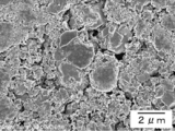
- FIG. 2 is a scanning electron micrograph of the surface of a positive electrode active material layer (positive electrode A) obtained in Example 1.
- FIG. 2 is a scanning electron micrograph of the surface of a positive electrode active material layer (positive electrode B) obtained in Example 1.
- FIG. 1 is a scanning electron micrograph of the surface of a positive electrode active material layer (positive electrode B) obtained in Example 1.
- a numerical range indicated by using “to” indicates a range including the numerical values described before and after “to” as the minimum value and the maximum value, respectively.
- the upper limit value or the lower limit value described in one numerical range may be replaced with the upper limit value or the lower limit value of another numerical range.
- the upper limit value or the lower limit value of the numerical range may be replaced with the values shown in the examples.
- the content of each component in the composition is the sum of the plurality of substances present in the composition unless there is a specific indication when there are a plurality of substances corresponding to each component in the composition. It means the content rate of.
- the particle size of each component in the composition is a mixture of the plurality of types of particles present in the composition unless there is a specific indication when there are a plurality of types of particles corresponding to each component in the composition. Means the value of.
- the term “layer” includes a configuration formed in a part in addition to a configuration formed in the entire surface when observed as a plan view.
- the term “lamination” indicates that layers are stacked, and two or more layers may be combined, or two or more layers may be detachable.
- the technology of the present disclosure can be widely applied to various non-aqueous secondary batteries including an electrode in a form in which an electrode active material layer (a positive electrode active material layer and a negative electrode active material layer) is formed on a current collector. Details will be described below.
- the positive electrode for a lithium ion secondary battery of the present disclosure includes a positive electrode active material layer containing insulating polyolefin particles and a conductive material.
- the positive electrode active material layer contains a positive electrode active material, insulating polyolefin particles, and a conductive material, and is formed on the positive electrode current collector.
- a positive electrode active material insulating polyolefin particles, and a conductive material
- a positive electrode active material paste, insulating polyolefin particles, a conductive material, and other materials such as a binder and water-soluble polymer used as necessary are dissolved or dispersed in a dispersion solvent to form a positive electrode mixture paste. This is applied to the positive electrode current collector and dried (wet method).
- the positive electrode current collector those commonly used in the field of lithium ion secondary batteries can be used. Specifically, stainless steel, aluminum, or a sheet containing titanium, foil, or the like can be given. Among these, an aluminum sheet or foil is preferable.
- the thickness of the sheet and foil is not particularly limited, but is preferably, for example, 1 ⁇ m to 500 ⁇ m, more preferably 2 ⁇ m to 100 ⁇ m, and still more preferably 5 ⁇ m to 50 ⁇ m.
- the positive electrode active material layer is formed on one or both surfaces in the thickness direction of the positive electrode current collector, contains a positive electrode active material, insulating polyolefin particles, and a conductive material, and, if necessary, a binder. Further, it may contain a water-soluble polymer.
- the positive electrode active material those commonly used in this field can be used, and examples thereof include lithium-containing composite metal oxides, olivine-type lithium salts, chalcogen compounds, and manganese dioxide.
- the lithium-containing composite metal oxide is a metal oxide containing lithium and a transition metal or a metal oxide in which a part of the transition metal in the metal oxide is substituted with a different element.
- examples of the different elements include Na, Mg, Sc, Y, Mn, Fe, Co, Ni, Cu, Zn, Al, Cr, Pb, Sb, V, and B.
- Mn, Al, Co, Ni, Mg and the like are preferable.
- the heterogeneous element may be one type or two or more types.
- a lithium-containing composite metal oxide is preferable as the positive electrode active material.
- the lithium-containing composite metal oxide include Li x CoO 2 , Li x NiO 2 , Li x MnO 2 , Li x Co y Ni 1-y O 2 , and Li x Co y M 1 1-y O z (formula M 1 represents at least one element selected from the group consisting of Na, Mg, Sc, Y, Mn, Fe, Ni, Cu, Zn, Al, Cr, Pb, Sb, V, and B.) , Li x Ni 1-y M 2 y O z where M 2 is from Na, Mg, Sc, Y, Mn, Fe, Co, Cu, Zn, Al, Cr, Pb, Sb, V, and B And at least one element selected from the group consisting of Li x Mn 2 O 4 , and Li x Mn 2 -y M 3 y O 4 (wherein M 3 is Na, Mg, Sc, Y, Fe) , Co
- x is 0 to 1.2
- y is 0 to 0.9
- z is 2.0 to 2.3.
- the x value indicating the molar ratio of lithium is increased or decreased by charging and discharging.
- the olivine type lithium salts such as LiFePO 4.
- the chalcogen compound include titanium disulfide and molybdenum disulfide.
- a positive electrode active material can be used individually by 1 type, or can use 2 or more types together.
- the positive electrode active material preferably contains a lithium manganese oxide represented by Li x Mn 2 O 4 or Li x Mn 2-y M 3 y O 4 from the viewpoint of safety.
- the content of lithium manganese oxide is preferably 30% by mass or more, and more preferably 40% by mass or more, based on the total amount of the positive electrode active material. .
- Examples of the insulating polyolefin particles in the present disclosure include particles made of polyethylene, polypropylene, polymethylpentene, polybutene, or modified products thereof.
- the insulating polyolefin particles particles made of polyethylene or a modified product of polyethylene or polypropylene or a modified product of polypropylene are preferable. Insulating polyolefin particles can be used singly or in combination of two or more.
- the melting point (Tm) of the insulating polyolefin particles is not particularly limited, but from the viewpoint of improving the handleability and safety of the lithium ion secondary battery, polyolefin particles having a melting point (Tm) of 70 ° C. to 160 ° C. are preferable. Polyolefin particles at 80 ° C. to 150 ° C. are more preferred, and polyolefin particles at 90 ° C. to 140 ° C. are even more preferred. As the melting point (Tm) of the polyolefin particles is lower, the PTC function is exhibited at a lower temperature, so that safety can be improved.
- the melting point (Tm) of the polyolefin particles can be calculated from the endothermic peak temperature after measuring the specific heat capacity of the polyolefin particles in the inert gas as a temperature function using, for example, a differential scanning calorimeter.
- the average particle diameter of the insulating polyolefin particles is preferably from 0.1 ⁇ m to 30 ⁇ m from the viewpoint that the positive electrode active material layer can be uniformly formed on the positive electrode current collector and the battery characteristics can be further improved. It is more preferably from 15 ⁇ m to more preferably from 2.5 ⁇ m to 10 ⁇ m. The smaller the average particle size of the polyolefin particles, the more the positive electrode active material layer tends to be formed on the positive electrode current collector, and the larger the average particle size of the polyolefin particles, the better the battery characteristics.
- the average particle diameter of the polyolefin particles is, for example, a positive electrode current collector in which a positive electrode active material layer containing polyolefin particles is formed to have a thickness of about 70 ⁇ m.
- a value obtained by arithmetically averaging the long side length values of all the polyolefin particles in the image of the scanning electron micrograph can be used.
- the content of the polyolefin particles is 0.1% by mass to 10% by mass in the total amount of the positive electrode active material layer from the viewpoint of achieving both battery characteristics and PTC function. %, More preferably 0.5% by mass to 8% by mass, and even more preferably 2.5% by mass to 6.5% by mass.
- the form of addition of the insulating polyolefin particles is not particularly limited as long as the polyolefin maintains the particle shape, and a dry powder form, a dispersed form in a solvent, or the like can be applied. From the viewpoint of preventing moisture from being mixed into the positive electrode mixture paste, it is preferable to use the powder after drying. From the viewpoint of achieving good dispersion of the polyolefin particles in the positive electrode mixture paste, it is preferable to use the powder after being dispersed in a solvent. .
- the solvent for dispersing the polyolefin particles is not particularly limited, and examples thereof include N-methyl-2-pyrrolidone (NMP), tetrahydrofuran, and dimethylformamide.
- Examples of the conductive material used for the positive electrode active material layer include carbon black, graphite, carbon fiber, and metal fiber.
- carbon black include acetylene black, ketjen black, channel black, furnace black, lamp black, and thermal black.
- Examples of graphite include natural graphite and artificial graphite.
- a conductive material can be used individually by 1 type or in combination of 2 or more types. The content of the conductive material in the case where the conductive material is used for the positive electrode active material layer is such that the insulating polyolefin particles and the conductive material contained in the positive electrode active material layer are from the viewpoint of achieving both battery characteristics and PTC function.
- the mass ratio (insulating polyolefin particles / conductive material) is preferably 0.15 / 0.85 to 0.85 / 0.15, preferably 0.3 / 0.7 to 0.7 / 0. Is more preferable, and an amount of 0.4 / 0.6 to 0.6 / 0.4 is even more preferable.
- the proportion of the conductive material is larger, the positive electrode active material layer tends to be excellent in battery characteristics, and as the proportion of the conductive material is smaller, the positive electrode active material layer tends to be superior in PTC function.
- binder examples include polyvinyl acetate, polymethyl methacrylate, nitrocellulose, fluororesin, rubber particles, and resins containing structural units derived from nitrile group-containing monomers. It is done.
- fluororesin examples include polytetrafluoroethylene (PTFE), polyvinylidene fluoride (PVDF), tetrafluoroethylene-hexafluoropropylene copolymer (FEP), and vinylidene fluoride-hexafluoropropylene copolymer.
- fluororesin examples include polytetrafluoroethylene (PTFE), polyvinylidene fluoride (PVDF), tetrafluoroethylene-hexafluoropropylene copolymer (FEP), and vinylidene fluoride-hexafluoropropylene copolymer.
- rubber particles examples include styrene-butadiene rubber particles and acrylonitrile rubber particles.
- the resin containing a structural unit derived from a nitrile group-containing monomer examples include a resin containing a structural unit derived from an acrylic nitrile group-containing monomer such as acrylonitrile or methacrylonitrile.
- a resin containing a structural unit derived from a nitrile group-containing monomer for example, a copolymer in which acrylic acid and a linear ether group are added to a polyacrylonitrile skeleton (binder, manufactured by Hitachi Chemical Co., Ltd., Product name: LSR7).
- a binder containing fluorine is preferable.
- a binder can be used individually by 1 type, and can be used in combination of 2 or more type as needed.
- water-soluble polymers examples include carboxymethyl cellulose, carboxymethyl cellulose derivatives such as sodium carboxymethyl cellulose, polyvinyl alcohol, polyvinyl pyrrolidone, water-soluble alginic acid derivatives, gelatin, carrageenan, glucomannan, pectin, and curdlan. , Gellan gum, polyacrylic acid derivatives and the like.
- the water-soluble polymer carboxymethyl cellulose derivatives, polyvinyl alcohol, polyvinyl pyrrolidone, and polyacrylic acid are preferable, carboxymethyl cellulose derivatives, polyvinyl pyrrolidone, and polyacrylic acid are more preferable, and carboxymethyl cellulose derivatives are more preferable.
- “polymer” means that the number average molecular weight is 1000 or more.
- the number average molecular weight of the water-soluble polymer is preferably 10,000 or more, more preferably 200,000 or more, and further preferably 300,000 or more from the viewpoint of dispersibility of the conductive particles.
- the weight average molecular weight of the water-soluble polymer is preferably 50000 or more, more preferably 1000000 or more, and further preferably 2000000 or more from the same viewpoint as described above.
- 5000000 or less are preferable.
- the number average molecular weight and the weight average molecular weight of the water-soluble polymer can be determined, for example, by connecting a GPC (Gel Permeation Chromatography) column to an HPLC (High Performance Liquid Chromatography) system equipped with a differential refractometer as a detector and an NaCl aqueous solution as an eluent. It can be calculated from a calibration curve using pullulan as a standard substance using a mixed solution of benzene and acetonitrile. Further, the viscosity (60 rotations) at 25 ° C.
- water-soluble polymer when the water-soluble polymer is made into a 1% by mass aqueous solution is preferably 100 mPa ⁇ s to 8000 mPa ⁇ s, more preferably 500 mPa ⁇ s to 6000 mPa ⁇ s, and more preferably 1000 mPa ⁇ s to 4000 mPa ⁇ s is more preferable.
- the current cutoff temperature of the positive electrode for a lithium ion secondary battery of the present disclosure is preferably set to 70 ° C. to 160 ° C., and more preferably set to 90 ° C. to 120 ° C. If the current cutoff temperature is set to 70 ° C to 160 ° C, the current is cut off when an abnormality occurs in the battery itself or various devices equipped with the battery to suppress heat generation, and the power from the battery to the various devices is reduced. Since supply etc. can be stopped, very high safety is obtained. Further, if the current interruption temperature is set to 90 ° C. to 120 ° C., there is an advantage that there is no malfunction during normal use, and the current can be reliably interrupted in the event of an abnormality such as overcharging.
- the current interruption temperature as described above depends on the melting point (Tm) of the polyolefin particles.
- Tm melting point
- polyethylene particles are preferably used as the polyolefin particles.
- said electric current interruption temperature shall be the temperature from which a DC resistance increase rate will be 110% or more with respect to DC resistance in 25 degreeC of a battery.
- the positive electrode active material layer can be formed, for example, by applying a positive electrode mixture paste on a positive electrode current collector, drying, and rolling as necessary.
- the positive electrode mixture paste can be prepared by adding a positive electrode active material to a dispersion medium together with a binder, a conductive material, and the like and mixing them.
- the dispersion medium for example, N-methyl-2-pyrrolidone (NMP), tetrahydrofuran, and dimethylformamide can be used.
- the packing density of the positive electrode active material layer described above Is preferably in the range of 2.2 g / cm 3 to 2.8 g / cm 3 , more preferably in the range of 2.3 g / cm 3 to 2.7 g / cm 3. More preferably, it is in the range of 3 to 2.6 g / cm 3 .
- the packing density of the positive electrode active material layer is 2.8 g / cm 3 or less, the non-aqueous electrolyte easily penetrates into the positive electrode active material layer, and the diffusion of lithium ions during charge / discharge with a large current is accelerated. Cycle characteristics tend to improve.
- the packing density of the positive electrode active material layer is 2.2 g / cm 3 or more, the contact between the positive electrode active material and the conductive material is sufficiently ensured to lower the electric resistance and improve the discharge rate characteristics. Tend to.
- the coating amount is preferably in the range of 100 g / m 2 to 300 g / m 2 , more preferably in the range of 150 g / m 2 to 250 g / m 2 , and 180 g / m 2 to 220 g / m 2 . It is more preferable to make the range. If the coating amount is 100 g / m 2 or more, the positive electrode active material layer will not be too thin, and a sufficient battery capacity can be obtained.
- the thickness of the positive electrode active material layer is preferably 50 ⁇ m to 150 ⁇ m, more preferably 60 ⁇ m to 120 ⁇ m, and still more preferably 70 ⁇ m to 110 ⁇ m.
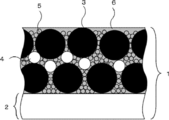
- FIG. 1 is a schematic cross-sectional view of a positive electrode for a lithium ion secondary battery of the present disclosure obtained by the above method.
- a positive electrode 1 for a lithium ion secondary battery is formed by binding a positive electrode active material 3, insulating polyolefin particles 4, and a conductive material 5 on a positive electrode current collector 2 with a binder 6. Is done.
- the insulating polyolefin particles melt and cover the surface of the positive electrode active material and the surface of the conductive material, so that the positive electrode active material-between the positive electrode current collector and the positive electrode active material- The conductive path between the positive electrode active materials is cut, and the electron transfer during charging and discharging is hindered. Thereby, the battery function when the battery abnormally generates heat is suppressed, and the safety of the battery is improved.
- the electrode for a lithium ion secondary battery of the present disclosure includes an electrode active material layer containing polyolefin particles and a resin containing a structural unit derived from a nitrile group-containing monomer.
- the electrode for a lithium ion secondary battery of the present disclosure may be a positive electrode including a positive electrode active material layer or a negative electrode including a negative electrode active material layer.
- the positive electrode active material layer contains at least a positive electrode active material and is formed on the positive electrode current collector.
- the positive electrode active material and other materials such as a conductive material, a binder, and a water-soluble polymer, which are used as necessary, are dry mixed to form a sheet, and this is pressure-bonded to the positive electrode current collector (dry method) ).
- a positive electrode active material and other materials such as a conductive material, a binder, and a water-soluble polymer used as necessary are dissolved or dispersed in a dispersion solvent to form a positive electrode mixture paste, which is used as a positive electrode current collector. Apply to body and dry (wet method).
- the positive electrode active material layer preferably contains, in addition to the positive electrode active material, polyolefin particles and a resin containing a structural unit derived from a nitrile group-containing monomer.
- the resin containing a structural unit derived from a polyolefin particle and a nitrile group-containing monomer will be described later.
- Examples of the positive electrode current collector include the same positive electrode current collectors as those exemplified in the above-described electrode for a lithium ion secondary battery.
- the positive electrode active material layer is formed on one or both surfaces in the thickness direction of the positive electrode current collector, contains the positive electrode active material, and further contains a conductive material, a binder, a water-soluble polymer, and the like as necessary. You may contain.
- Examples of the positive electrode active material include the same positive electrode active materials as those exemplified in the above-described electrode for a lithium ion secondary battery.
- As the positive electrode active material Li x Mn 2 O 4 or Li x Mn 2-y M 3 y O 4 (wherein, M 3 is Na, Mg, Sc, Y, Fe, Co, Ni, from the viewpoint of safety) And at least one element selected from the group consisting of Cu, Zn, Al, Cr, Pb, Sb, V, and B.
- lithium manganese oxide is used as the positive electrode active material
- the content of lithium manganese oxide is preferably 30% by mass or more, and more preferably 40% by mass or more, based on the total amount of the positive electrode active material. .
- Examples of the conductive material that may be used for the positive electrode active material layer include the same conductive materials as those exemplified for the electrode for a lithium ion secondary battery described above.
- Examples of the binder that may be used for the positive electrode active material layer include the same binders as those exemplified for the electrode for a lithium ion secondary battery described above.
- As the binder it is preferable to use a resin containing a structural unit derived from a nitrile group-containing monomer.
- the positive electrode active material layer can be formed, for example, by applying a positive electrode mixture paste on a positive electrode current collector, drying, and rolling as necessary.
- the positive electrode mixture paste can be prepared by adding a positive electrode active material to a dispersion medium together with a binder, a conductive material, and the like and mixing them.
- the dispersion medium for example, N-methyl-2-pyrrolidone (NMP), tetrahydrofuran, and dimethylformamide can be used.
- the packing density of the positive electrode active material layer is preferably in the range of 2.2g / cm 3 ⁇ 2.8g / cm 3, more preferably in the range of 2.3g / cm 3 ⁇ 2.7g / cm 3, 2.4g / cm 3 ⁇ More preferably, it is in the range of 2.6 g / cm 3 .
- the coating amount is preferably in the range of 100 g / m 2 to 300 g / m 2 , more preferably in the range of 150 g / m 2 to 250 g / m 2 , and 180 g / m 2 to 220 g / m 2 . It is more preferable to make the range.
- the thickness of the positive electrode active material layer is preferably 50 ⁇ m to 150 ⁇ m, more preferably 60 ⁇ m to 120 ⁇ m, and still more preferably 70 ⁇ m to 110 ⁇ m.
- the negative electrode active material layer contains at least a negative electrode active material and is formed on the negative electrode current collector.
- the negative electrode active material and other materials such as conductive materials, binders, and water-soluble polymers that are used as needed are mixed in a dry form to form a sheet, which is then pressure-bonded to the negative electrode current collector (dry method) ).
- the negative electrode active material and other materials such as a conductive material, a binder, and a water-soluble polymer used as necessary are dissolved or dispersed in a dispersion solvent to form a negative electrode mixture paste, which is used as a negative electrode current collector. Apply to body and dry (wet method).
- the negative electrode active material layer may contain, in addition to the negative electrode active material, polyolefin particles and a resin containing a structural unit derived from a nitrile group-containing monomer.
- the resin containing a structural unit derived from a polyolefin particle and a nitrile group-containing monomer will be described later.
- the negative electrode current collector those commonly used in the field of lithium ion secondary batteries can be used. Specifically, a sheet containing stainless steel, nickel, copper, or the like, a foil, or the like can be given.
- the thickness of the sheet and foil is not particularly limited, but is preferably, for example, 1 ⁇ m to 500 ⁇ m, more preferably 2 ⁇ m to 100 ⁇ m, and still more preferably 5 ⁇ m to 50 ⁇ m.
- the negative electrode active material layer is formed on one or both surfaces in the thickness direction of the negative electrode current collector, contains the negative electrode active material, and further contains a conductive material, a binder, a water-soluble polymer, an increase, if necessary. You may contain sticky materials.
- the negative electrode active material a material that can occlude and release lithium ions and that is commonly used in the field of lithium ion secondary batteries can be used.
- the negative electrode active material include lithium metal, lithium alloy, intermetallic compound, carbon material, organic compound, inorganic compound, metal complex, and organic polymer compound.
- a negative electrode active material can be used individually by 1 type or in combination of 2 or more types.
- a carbon material is preferable as the negative electrode active material.
- Carbon materials include natural graphite (flaky graphite, etc.), graphite such as artificial graphite, carbon black such as acetylene black, ketjen black, channel black, furnace black, lamp black, thermal black, amorphous carbon, carbon fiber Etc.
- the volume average particle size of the carbon material is preferably 0.1 ⁇ m to 60 ⁇ m, and more preferably 0.5 ⁇ m to 30 ⁇ m.
- the BET specific surface area of the carbon material is preferably 1 m 2 / g to 10 m 2 / g.
- the spacing (d 002 ) between the carbon hexagonal planes in the X-ray wide angle diffraction method is 3.35 to 3.40 mm, and the crystallites in the c-axis direction Graphite having (Lc) of 100% or more is preferable.
- amorphous carbon having an interval (d 002 ) between carbon hexagonal planes in the X-ray wide-angle diffraction method of 3.5 to 3.95 cm. Is preferred.
- Examples of the conductive material that may be used for the negative electrode active material layer include the same conductive materials as those exemplified for the positive electrode active material layer. Moreover, as a binder which may be used for a negative electrode active material layer, the binder similar to what was illustrated with the positive electrode active material layer is mentioned. When graphite is used as the negative electrode active material, it is preferable that styrene butadiene rubber or acrylic rubber is included as the binder. Examples of the water-soluble polymer that may be used for the negative electrode active material layer include water-soluble polymers similar to those exemplified for the positive electrode active material layer.
- the negative electrode active material layer can be formed, for example, by applying a negative electrode mixture paste on a negative electrode current collector, drying, and rolling as necessary.
- the negative electrode mixture paste can be prepared, for example, by adding a negative electrode active material to a dispersion medium together with a conductive material, a binder, a water-soluble polymer, a thickener, and the like as necessary.
- the dispersion medium for example, N-methyl-2-pyrrolidone (NMP) and water can be used.
- At least one of the positive electrode active material layer and the negative electrode active material layer described above contains polyolefin particles.
- polyolefin particles examples include particles made of polyethylene, polypropylene, polymethylpentene, polybutene, or modified products thereof.
- the polyolefin particles particles made of polyethylene or a modified product of polyethylene, or polypropylene or a modified product of polypropylene are preferable.
- Polyolefin particles can be used singly or in combination of two or more.
- the melting point (Tm) of the polyolefin particles is not particularly limited, but from the viewpoint of improving the handleability and safety of the lithium ion secondary battery, polyolefin particles having a melting point (Tm) of 70 ° C. to 160 ° C. are preferable, and 90 ° C. to Polyolefin particles at 140 ° C. are more preferred, and polyolefin particles at 100 ° C. to 130 ° C. are even more preferred. As the melting point (Tm) of the polyolefin particles is lower, the PTC function is exhibited at a lower temperature, so that safety can be improved.
- the melting point (Tm) of the polyolefin particles can be calculated from the endothermic peak temperature after measuring the specific heat capacity of the polyolefin particles in the inert gas as a temperature function using, for example, a differential scanning calorimeter.
- the average particle diameter of the polyolefin particles is preferably 0.1 ⁇ m to 30 ⁇ m, and preferably 0.5 ⁇ m to 15 ⁇ m from the viewpoint that the electrode active material layer can be uniformly formed on the current collector and the battery characteristics can be further improved. It is more preferable that the thickness is 2.5 ⁇ m to 10 ⁇ m.
- the smaller the average particle size of the polyolefin particles the more easily the electrode active material layer can be formed on the current collector.
- the larger the average particle size of the polyolefin particles the better the battery characteristics.
- the average particle diameter of the polyolefin particles is, for example, a transmission type in which the center part of a current collector in which an electrode active material layer containing polyolefin particles is formed to have a thickness of about 70 ⁇ m is in the range of 50 ⁇ m in length ⁇ 50 ⁇ m in width.
- the value of the long side length of all the polyolefin particles in the image of the electron micrograph can be a numerical value obtained by arithmetic averaging.
- the content of the polyolefin particles is preferably 0.1% by mass to 10% by mass in the total amount of the electrode active material layer from the viewpoint of achieving both battery characteristics and PTC function. 0.5 mass% to 8 mass% is more preferable, and 2.5 mass% to 6 mass% is still more preferable. The greater the proportion of polyolefin particles, the more likely the electrode active material layer has an excellent PTC function, and the smaller the proportion of polyolefin particles, the more likely the electrode active material layer has excellent battery characteristics.
- the addition form of the polyolefin particles is not particularly limited as long as the polyolefin maintains a particulate form, and a dry powder form, a dispersed form in a solvent, or the like can be applied.
- the polyolefin particles are included in the positive electrode active material layer, it is preferable to dry the powder.
- it is preferably used by dispersing in a solvent.
- the solvent for dispersing the polyolefin particles is not particularly limited, and examples thereof include N-methyl-2-pyrrolidone (NMP), tetrahydrofuran, and dimethylformamide.
- NMP N-methyl-2-pyrrolidone
- tetrahydrofuran tetrahydrofuran
- dimethylformamide dimethylformamide
- At least one of the positive electrode active material layer and the negative electrode active material layer described above contains a resin containing a structural unit derived from a nitrile group-containing monomer in addition to the polyolefin particles.
- the resin containing a structural unit derived from a nitrile group-containing monomer is preferably soluble or easily soluble in an organic solvent.
- the resin containing a structural unit derived from a nitrile group-containing monomer examples include copolymers of (meth) acrylonitrile and other compounds having an ethylenically unsaturated bond.
- a resin containing a structural unit derived from a nitrile group-containing monomer is represented by a structural unit derived from a nitrile group-containing monomer and the following formula (I): And at least one structural unit selected from the group consisting of monomer-derived structural units represented by the following formula (II).
- the resin containing the structural unit derived from a nitrile group containing monomer contains the structural unit derived from a carboxy group containing monomer from a viewpoint which can further improve binding property.
- R 1 is a hydrogen atom or a methyl group
- R 2 is a hydrogen atom or a monovalent hydrocarbon group
- n is an integer of 1 to 50
- R 3 is a hydrogen atom or a methyl group
- R 4 is an alkyl group having 4 to 100 carbon atoms.
- nitrile group-containing monomer is not particularly limited.
- nitrile group-containing monomers include acrylic nitrile group-containing monomers such as acrylonitrile and methacrylonitrile, cyan nitrile group-containing monomers such as ⁇ -cyanoacrylate and dicyanovinylidene, and fumarate nitrile groups such as fumaronitrile. Containing monomers and the like. Among these, acrylonitrile is preferable from the viewpoints of flexibility and flexibility of the electrode. These nitrile group-containing monomers can be used singly or in combination of two or more.
- the content of structural units derived from acrylonitrile or methacrylonitrile is preferably 40% by mass to 98% by mass with respect to the total amount of the binder. 50 mass% to 96 mass% is more preferable, and 60 mass% to 95 mass% is still more preferable.
- the monomer represented by the formula (I) is not particularly limited.
- R 1 is a hydrogen atom or a methyl group.
- n is an integer of 1 to 50, preferably an integer of 2 to 30, and more preferably an integer of 2 to 10.
- R 2 is a hydrogen atom or a monovalent hydrocarbon group, for example, preferably a hydrocarbon group having 1 to 50 carbon atoms, more preferably a hydrocarbon group having 1 to 25 carbon atoms, More preferred is a hydrocarbon group of 1 to 12. If the number of carbon atoms of the hydrocarbon group is 50 or less, sufficient swelling resistance to the electrolytic solution tends to be obtained.
- a hydrocarbon group an alkyl group and a phenyl group are preferable, for example.
- R 2 is particularly preferably an alkyl group having 1 to 12 carbon atoms or a phenyl group. This alkyl group may be either a straight chain or a branched chain.
- R 2 is an alkyl group or a phenyl group
- the hydrogen atom that the alkyl group or the phenyl group has is a halogen atom such as a fluorine atom, a chlorine atom, a bromine atom, or an iodine atom, a nitrogen atom-containing group, a phosphorus atom-containing group, oxygen It may be substituted with an atom-containing group, an aromatic group or a cycloalkyl group having 3 to 10 carbon atoms.
- Examples of the monomer represented by the formula (I) include commercially available ethoxydiethylene glycol acrylate (manufactured by Kyoeisha Chemical Co., Ltd., trade name: Light acrylate EC-A), methoxytriethylene glycol acrylate (Kyoeisha Chemical Co., Ltd.).
- EO means an ethyleneoxy group
- n means the number of structural units of the ethyleneoxy group.
- methoxytriethylene glycol acrylate (R 1 in formula (I) is a hydrogen atom
- R 2 is a methyl group
- n is 3 in terms of reactivity when copolymerized with a nitrile group-containing monomer.
- R 1 in formula (I) is a hydrogen atom
- R 2 is a methyl group
- n is 3 in terms of reactivity when copolymerized with a nitrile group-containing monomer.
- the monomer represented by the formula (II) is not particularly limited.
- R 3 is a hydrogen atom or a methyl group.
- R 4 is an alkyl group having 4 to 100 carbon atoms, preferably 4 to 50 carbon atoms, more preferably 6 to 30 carbon atoms, and still more preferably 8 to 15 carbon atoms. If the carbon number of the alkyl group is 4 or more, the electrode tends to exhibit sufficient flexibility, and if the carbon number of the alkyl group is 100 or less, sufficient swelling resistance to the electrolytic solution can be obtained. There is a tendency.
- the alkyl group constituting R 4 may be either a straight chain or a branched chain.
- the hydrogen atom contained in the alkyl group constituting R 4 is a halogen atom such as a fluorine atom, a chlorine atom, a bromine atom or an iodine atom, a nitrogen atom-containing group, a phosphorus atom-containing group, an oxygen atom-containing group, an aromatic group, It may be substituted with a cycloalkyl group having 3 to 10 carbon atoms.
- the alkyl group constituting R 4 include a linear or branched saturated alkyl group, and a halogenated alkyl group such as a fluoroalkyl group, a chloroalkyl group, a bromoalkyl group, and an iodide alkyl group.
- R 4 is a linear or branched saturated alkyl group, for example, n-butyl (meth) acrylate, isobutyl (meth) acrylate, t-butyl ( (Meth) acrylate, amyl (meth) acrylate, isoamyl (meth) acrylate, hexyl (meth) acrylate, heptyl (meth) acrylate, octyl (meth) acrylate, 2-ethylhexyl (meth) acrylate, nonyl (meth) acrylate, decyl ( (Meth) acrylate, isodecyl (meth) acrylate, lauryl (meth) acrylate, tridecyl (meth) acrylate, hexadecyl (meth) acrylate, stearyl (meth) acrylate, isostearyl (meth)
- R 4 is a fluoroalkyl group, for example, 1,1-bis (trifluoromethyl) -2,2,2-trifluoroethyl acrylate, 2,2,3,3,4,4,4- Heptafluorobutyl acrylate, 2,2,3,4,4,4-hexafluorobutyl acrylate, nonafluoroisobutyl acrylate, 2,2,3,3,4,4,5,5-octafluoropentyl acrylate, 2 , 2,3,3,4,4,5,5,5-nonafluoropentyl acrylate, 2,2,3,3,4,4,5,5,6,6,6-undecafluorohexyl acrylate, 2,2,3,3,4,5,5,6,6,7,7,8,8,8-pentadecafluorooctyl acrylate, 3,3,4,4,5,5,6 6, 7, 7, 8, 8, 9, 9, 10 , 10,10-heptadecafluorodecyl acrylate, 2,2,3,3,4,5,5,6,6,7,7
- the structural unit derived from the monomer represented by the formula (I) and the formula (II) is preferably 1% by mass to 50% by mass with respect to the total amount of the binder, and 2% by mass to 30%. More preferably, it is more preferably 3% by mass to 20% by mass.
- the carboxy group-containing monomer is not particularly limited.
- the carboxy group-containing monomer include acrylic carboxy group-containing monomers such as acrylic acid and methacrylic acid, croton carboxy group-containing monomers such as crotonic acid, and maleic carboxy groups such as maleic acid and anhydrides thereof.
- Itacon carboxy group-containing monomers such as it containing monomers, itaconic acid and anhydrides thereof, and citraconic carboxy group containing monomers such as citraconic acid and anhydrides thereof.
- acrylic acid is preferable from the viewpoints of flexibility and adhesiveness of the electrode.
- These carboxyl group-containing monomers can be used alone or in combination of two or more.
- the content of the structural unit derived from the carboxy group-containing monomer is preferably 0.1% by mass to 20% by mass with respect to the total amount of the binder, and is 1% by mass. More preferably, it is preferably ⁇ 10% by mass, more preferably 2% by mass to 6% by mass.
- the resin containing the structural unit derived from the nitrile group-containing monomer is represented by the structural unit derived from the nitrile group-containing monomer, the structural unit derived from the monomer represented by the formula (I), and the formula (II).
- the structural unit derived from the monomer represented by the formula (I) is represented by the formula (I)
- the formula (II) is represented by the structural unit derived from the monomer represented by the formula (I)
- other monomers different from these monomers can also be appropriately combined.
- Other monomers are not particularly limited.
- monomers include short chain (meth) acrylates such as methyl (meth) acrylate, ethyl (meth) acrylate, and propyl (meth) acrylate, vinyl halides such as vinyl chloride, vinyl bromide, and vinylidene chloride.
- styrene compounds such as styrene, ⁇ -methylstyrene, sodium styrenesulfonate, imide compounds such as maleimide and N-phenylmaleimide, amide compounds such as (meth) acrylamide, vinyl acetate, sodium (meth) allylsulfonate, ( Examples include sodium (meth) allyloxybenzenesulfonate, 2-acrylamido-2-methylpropanesulfonic acid and its salts.
- (Meth) acrylamide” means acrylamide or methacrylamide
- (meth) allyl” means allyl or methallyl.
- Resin containing a structural unit derived from a nitrile group-containing monomer is a structural unit derived from a nitrile group-containing monomer, a structural unit derived from a carboxy group-containing monomer, and a monomer represented by the formula (I)
- the molar ratio with respect to one structural unit is, for example, preferably 0.01 to 0.2 mol of a structural unit derived from a carboxy group-containing monomer with respect to 1
- the total of structural units derived from the monomer represented by formula (I) or formula (II) is preferably 0.001 mol to 0.2 mol.
- the amount is preferably 0.003 mol to 0.05 mol, more preferably 0.005 mol to 0.03 mol.
- the structural unit derived from the carboxy group-containing monomer is 0.01 mol to 0.2 mol, and the total of the structural units derived from the monomer represented by formula (I) or formula (II) is 0.001 mol. If it is ⁇ 0.2 mol, the adhesion to the current collector, particularly the current collector using copper foil, and the swelling resistance against the electrolytic solution are excellent, and the flexibility and flexibility of the electrode tend to be good. is there.
- the content thereof is preferably 0.005 mol to 0.1 mol, more preferably 0.01 mol to 0 mol, relative to 1 mol of the nitrile group-containing monomer. 0.06 mole, more preferably 0.03 mole to 0.05 mole.
- the structural unit derived from the nitrile group-containing monomer is preferably 50 mol% or more, more preferably 70 mol% or more, and more preferably 80 mol% or more based on the total amount of the binder. More preferably.
- the current interruption temperature of the lithium ion secondary battery electrode of the present disclosure is preferably set to 70 ° C. to 160 ° C., and more preferably set to 90 ° C. to 120 ° C. If the current cutoff temperature is set to 70 ° C to 160 ° C, the current is cut off when an abnormality occurs in the battery itself or various devices equipped with the battery to suppress heat generation, and the power from the battery to the various devices is reduced. Since supply etc. can be stopped, very high safety is obtained. Further, if the current interruption temperature is set to 90 ° C.
- the current interruption temperature as described above depends on the melting point (Tm) of the polyolefin particles.
- Tm melting point
- polyethylene particles are preferably used as the polyolefin particles.
- said electric current interruption temperature shall be the temperature from which a DC resistance increase rate will be 110% or more with respect to DC resistance in 25 degreeC of a battery.
- the lithium ion secondary battery according to the present disclosure includes at least one electrode selected from the group consisting of the positive electrode for a lithium ion secondary battery and the electrode for a lithium ion secondary battery described above.
- the lithium ion secondary battery of this indication can take the same composition as the conventional lithium ion secondary battery except the cathode for lithium ion secondary batteries or the electrode for lithium ion secondary batteries mentioned above.
- the lithium ion secondary battery of the present disclosure includes a positive electrode, a negative electrode, an insulating layer, and a nonaqueous electrolyte.
- the positive electrode is provided so as to face the negative electrode through an insulating layer described later, and includes a positive electrode current collector and a positive electrode active material layer.
- the positive electrode may be the above-described positive electrode for a lithium ion secondary battery, may be the above-described electrode for a lithium ion secondary battery, or may be a conventionally known positive electrode.
- the negative electrode is provided so as to face the positive electrode through an insulating layer described later, and includes a negative electrode current collector and a negative electrode active material layer.
- the negative electrode may be the above-described electrode for a lithium ion secondary battery or a conventionally known negative electrode.
- the insulating layer (hereinafter sometimes referred to as a separator) is provided so as to be interposed between the positive electrode and the negative electrode, and insulates the positive electrode from the negative electrode.
- a separator an ion-permeable material such as an inorganic porous film can be used.
- the separator those commonly used in the field of lithium ion secondary batteries can be used, and examples thereof include a resin porous sheet.
- the resin constituting the resin porous sheet include polyolefins such as polyethylene and polypropylene, polyamides, polyamideimides, and polyesters. Non-woven fabrics, woven fabrics and the like are also included in the resin porous sheet.
- a porous sheet having pores formed in the inside having a diameter of about 0.05 ⁇ m to 0.15 ⁇ m is preferable.
- Such a porous sheet has ion permeability, mechanical strength, and insulation at a high level.
- the thickness of the porous sheet is not particularly limited, but is preferably 0.5 ⁇ m to 30 ⁇ m, and more preferably 1 ⁇ m to 20 ⁇ m.
- the inorganic porous film mainly contains an inorganic compound and has high heat resistance.
- the inorganic compound include inorganic oxides such as alumina and silica, inorganic nitrides such as BN and Si 3 N 4 , and porous inorganic compounds such as zeolite. These inorganic compounds can be used individually by 1 type or in combination of 2 or more types.
- the inorganic porous film may further contain a heat resistant resin. Although it does not restrict
- the thickness of the inorganic porous film is not particularly limited, but is preferably 0.5 ⁇ m to 30 ⁇ m, and more preferably 1 ⁇ m to 20 ⁇ m.
- Nonaqueous electrolyte examples include a liquid non-aqueous electrolyte, a gel-like non-aqueous electrolyte, and a solid electrolyte (for example, a polymer solid electrolyte).
- the liquid non-aqueous electrolyte contains a solute (supporting salt) and a non-aqueous solvent, and further contains various additives as necessary. Solutes usually dissolve in non-aqueous solvents.
- the insulating layer is impregnated with the liquid non-aqueous electrolyte.
- borates include lithium bis (1,2-benzenediolate (2-)-O, O ′) borate, bis (2,3-naphthalenedioleate (2-)-O, O ′) boric acid.
- imide salts include lithium bistrifluoromethanesulfonate imide ((CF 3 SO 2 ) 2 NLi), lithium trifluoromethanesulfonate nonafluorobutanesulfonate ((CF 3 SO 2 ) (C 4 F 9 SO 2 ) NLi ), Lithium bispentafluoroethanesulfonate imide ((C 2 F 5 SO 2 ) 2 NLi), and the like.
- a solute may be used individually by 1 type, and may be used in combination of 2 or more type as needed.
- the amount of the solute dissolved in the nonaqueous solvent is preferably 0.5 mol / L to 2 mol / L.
- non-aqueous solvent those commonly used in this field can be used.
- cyclic carbonate ester, chain carbonate ester, and cyclic carboxylic acid ester are mentioned.
- the cyclic carbonate include propylene carbonate (PC) and ethylene carbonate (EC).
- the chain carbonate include diethyl carbonate (DEC), ethyl methyl carbonate (EMC), and dimethyl carbonate (DMC).
- the cyclic carboxylic acid ester include ⁇ -butyrolactone (GBL) and ⁇ -valerolactone (GVL).
- a non-aqueous solvent may be used individually by 1 type, and may be used in combination of 2 or more type as needed.
- vinylene carbonate (VC) in a nonaqueous solvent from a viewpoint which can improve a battery characteristic more.
- the content when vinylene carbonate (VC) is contained is preferably 0.1% by mass to 2% by mass, and more preferably 0.2% by mass to 1.5% by mass with respect to the total amount of the nonaqueous solvent.
- a coin-type battery can be manufactured as follows, for example. First, the positive electrode and the negative electrode are cut into a circle smaller than the coin outer can. A laminated body in which the positive electrode, the insulating layer, and the negative electrode are laminated in this order is manufactured, and in that state, accommodated in the coin outer can, and after pouring the nonaqueous electrolyte into the coin outer can, the coin outer can is sealed. . Thereby, a lithium ion secondary battery is obtained.
- a laminate-type lithium ion secondary battery can be manufactured, for example, as follows. First, the positive electrode and the negative electrode are cut into squares, and tabs are welded to the respective electrodes to produce positive and negative electrode terminals. A laminated body in which the positive electrode, the insulating layer, and the negative electrode are laminated in this order is prepared, and accommodated in an aluminum laminate pack in that state, and the positive and negative electrode terminals are taken out of the aluminum laminate pack and sealed. Next, the nonaqueous electrolyte is poured into the aluminum laminate pack, and the opening of the aluminum laminate pack is sealed. Thereby, a lithium ion secondary battery is obtained.
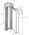
- the 18650 type lithium ion secondary battery 10 can be manufactured, for example, as follows. First, the positive electrode and the negative electrode are cut into strips, and tabs are welded to the respective electrodes to produce positive and negative electrode terminals. An electrode group 14 in which a strip-like positive electrode 11 and a negative electrode 12 are wound in a cross-sectional spiral shape through a separator 13 is produced, and in that state, accommodated in a bottomed cylindrical battery case 15 made of steel plated with nickel. To do. A ribbon-like positive electrode tab terminal made of aluminum having one end fixed to the positive electrode 11 is led out on the upper end surface of the electrode group 14.
- the other end of the positive electrode tab terminal is joined by ultrasonic welding to the lower surface of a disk-shaped battery lid that is disposed on the upper side of the electrode group 14 and serves as a positive external terminal.
- a ribbon-shaped negative electrode tab terminal made of copper with one end fixed to the negative electrode 12 is led to the lower end surface of the electrode group 14.
- the other end of the negative electrode tab terminal is joined to the inner bottom of the battery container 15 by resistance welding. Therefore, the positive electrode tab terminal and the negative electrode tab terminal are respectively led out to the opposite sides of the both end surfaces of the electrode group 14. Note that an insulation coating is applied to the entire outer peripheral surface of the electrode group 14.
- the nonaqueous electrolyte is poured into the battery container 15, and the battery lid is caulked and fixed to the upper part of the battery container 15 through an insulating resin gasket. For this reason, the inside of the lithium ion secondary battery 10 is sealed.
- the resistance increase rate of the DC resistance at 120 ° C. is 110% or more with respect to the DC resistance at 25 ° C. More preferably, it is 140% or more.
- the lithium ion secondary battery of the present disclosure has high safety and high output, and can be suitably used for the same applications as conventional non-aqueous electrolyte secondary batteries. In particular, it can be suitably used as a power source for various portable electronic devices such as a mobile phone, a notebook computer, a portable information terminal, an electronic dictionary, and a game machine.
- the lithium ion secondary battery of the present disclosure can also be applied to uses such as for power storage, transportation equipment such as electric vehicles and hybrid vehicles.
- Example 1 Production of positive electrode LiMn 2 O 4 (positive electrode active material, manufactured by Mitsui Kinzoku Mining Co., Ltd.) and acetylene black (conductive material, trade name: HS-100, average particle size 48 nm (Electrochemical Co., Ltd.) Catalog value), manufactured by Denki Kagaku Kogyo Co., Ltd., polyethylene particles (insulating polyolefin particles, trade name: Chemipearl (registered trademark) W410, average particle size 9.5 ⁇ m (catalog value from Mitsui Chemicals, Inc.), melting point 110 ° C (Mitsui Chemicals, Inc.
- FIG. 3 shows a scanning electron micrograph of the surface of the positive electrode active material layer (positive electrode A) obtained in Example 1.
- FIG. 4 shows a scanning electron micrograph of the surface of the positive electrode active material layer (positive electrode B) obtained in Example 1.
- This negative electrode mixture paste was applied to a 10 ⁇ m thick copper foil (negative electrode current collector), dried at 100 ° C. for 30 minutes, and then rolled to a thickness of 62 ⁇ m, a coating amount of 60 g / m 2 , and a mixture density of 0.
- a negative electrode active material layer of 97 g / cm 3 was formed to produce a negative electrode.
- Example 2 The mass ratio of the solid content of the positive electrode mixture paste (positive electrode active material: conductive material: insulating polyolefin particles: binder) was mixed so as to be 90.0: 4.5: 4.5: 1.0 A battery for electrode evaluation was produced in the same manner as in Example 1 except that.
- Example 3 The mass ratio of the solid content of the positive electrode mixture paste (positive electrode active material: conductive material: insulating polyolefin particles: binder) was mixed to 88.0: 4.5: 6.5: 1.0. A battery for electrode evaluation was produced in the same manner as in Example 1 except that.
- Example 4 The mass ratio of the solid content of the positive electrode mixture paste (positive electrode active material: conductive material: insulating polyolefin particles: binder) was mixed to 84.5: 4.5: 10.0: 1.0. A battery for electrode evaluation was produced in the same manner as in Example 1 except that.
- Insulating polyolefin particles include polyethylene particles (insulating polyolefin particles, trade name: Chemipearl (registered trademark) W410, average particle size 9.5 ⁇ m (Mitsui Chemicals catalog value), melting point 110 ° C. (Mitsui Chemicals, Inc.) ) Catalog value) is dried and powdered) instead of polyethylene particles (insulating polyolefin particles, trade name: Chemipearl (registered trademark) W4005, average particle size 0.6 ⁇ m (Mitsui Chemicals, Inc. catalog value)
- a battery for electrode evaluation was produced in the same manner as in Example 2 except that a melting point of 110 ° C. (catalog value of Mitsui Chemicals Co., Ltd.) was used.
- Example 6 Other than using a copolymer (binder, manufactured by Hitachi Chemical Co., Ltd., trade name: LSR7) in which acrylic acid and a linear ether group are added to the polyacrylonitrile skeleton instead of the polyvinylidene fluoride solution as the binder In the same manner as in Example 2, a battery for electrode evaluation was produced.
- a copolymer (binder, manufactured by Hitachi Chemical Co., Ltd., trade name: LSR7) in which acrylic acid and a linear ether group are added to the polyacrylonitrile skeleton instead of the polyvinylidene fluoride solution as the binder
- conductive polyolefin particles Polyethylene particles (insulating polyolefin particles, trade name: Chemipearl (registered trademark) W410, average particle size 9.5 ⁇ m (Mitsui Chemicals catalog value), melting point 110 ° C. (Mitsui (Catalog Co., Ltd. catalog)) and acetylene black (conductive particles, trade name: HS-100, average particle size 48 nm (Electrochemical Industry Co., Ltd. catalog value), Electrochemical Industry ( And kneading and extrusion molding evaluation test equipment (product name: Labo Plast Mill, manufactured by Toyo Seiki Seisakusho Co., Ltd.) to a mass ratio of 0.5 / 0.5. Thus, conductive polyolefin particles were produced.
- a positive electrode a The positive electrode A was heated in a thermostat set at 120 ° C. for 15 minutes to obtain a positive electrode B.
- This negative electrode mixture paste was applied to a 10 ⁇ m thick copper foil (negative electrode current collector), dried at 100 ° C. for 30 minutes, and then rolled to a thickness of 62 ⁇ m, a coating amount of 60 g / m 2 , and a mixture density of 0.
- a negative electrode active material layer of 97 g / cm 3 was formed to produce a negative electrode.
- the produced positive electrode A and positive electrode B were each cut into a circle having a diameter of 14 mm to obtain a positive electrode for evaluation.
- the produced negative electrode was cut into a circle having a diameter of 16 mm to obtain an evaluation negative electrode.
- a laminate in which the positive and negative electrodes are stacked so that the active material layers face each other through a separator (trade name: Hypore, manufactured by Asahi Kasei E-Materials Co., Ltd., cut into a circle having a diameter of 19 mm) made of a polyethylene microporous membrane. was made.
- I (I 1C + I 3C + I 5C ) / 3
- V ( ⁇ V 1C + ⁇ V 3C + ⁇ V 5C ) / 3
- I 1C , I 3C , and I 5C are respectively corresponding 1C, 3C, and The discharge current value at 5C is shown, and ⁇ V 1C , ⁇ V 3C , and ⁇ V 5C show the voltage change 10 seconds after the start of discharge at the corresponding discharge current value.
- Table 1 shows the evaluation results of Examples 1 to 6 and Comparative Examples 1 and 2.
- surface represents the compounding ratio (mass ratio) of the said component.
- “-” Means that the component is not blended.
- the batteries for evaluating electrodes of Examples 1 to 6 in which the positive electrode active material layer includes insulating polyolefin particles are comparative examples in which the positive electrode active material layer does not include insulating polyolefin particles while the PTC function is exhibited.
- the battery for electrode evaluation 1 does not exhibit the PTC function. This suggests that the insulating polyolefin particles have an effect of imparting a PTC function to the battery.
- the PTC functions of Examples 1 to 4 improved as the content of insulating polyolefin particles increased, suggesting that a safer battery can be obtained as the content of insulating polyolefin particles increases.
- Comparative Example 2 is an electrode evaluation battery using conductive polyolefin particles in which a polyolefin and a conductive material are mixed in advance. Although the content of the polyolefin and the conductive material in the positive electrode active material layer of Comparative Example 2 is equivalent to that of Example 2, the electrode evaluation battery of Comparative Example 2 has poor rate characteristics. This is because the conductive material is present in the polyolefin, so that the effect as the conductive material is reduced.
- an aqueous solution obtained by dissolving 0.968 g of a polymerization initiator ammonium persulfate in 76 g of purified water was added, and immediately, 183.8 g of nitrile group-containing monomer acrylonitrile, 9.7 g of acrylic acid of carboxy group-containing monomer ( 0.039 mol ratio relative to 1 mol of acrylonitrile) and methoxytriethylene glycol acrylate of the monomer represented by formula (I) (manufactured by Shin-Nakamura Chemical Co., Ltd., trade name: NK ester AM-30G) ) 6.5 g (a ratio of 0.0085 mol with respect to 1 mol of acrylonitrile) was added dropwise over 2 hours while maintaining the temperature of the system at 74 ° C.
- formula (I) manufactured by Shin-Nakamura Chemical Co., Ltd., trade name: NK ester AM-30G
- reaction solution was filtered with suction, and the collected wet precipitate was washed three times with 1800 g of purified water, and then vacuum-dried at 80 ° C. for 10 hours to obtain a resin A containing a structural unit derived from a nitrile group-containing monomer. Obtained.
- Example 7 (1) Production of positive electrode LiMn 2 O 4 (positive electrode active material, manufactured by Mitsui Kinzoku Mining Co., Ltd.) and acetylene black (conductive material, trade name: HS-100, average particle size 48 nm (Electrochemical Co., Ltd.) Catalog value), manufactured by Denki Kagaku Kogyo Co., Ltd., Resin A prepared in Synthesis Example 1, polyethylene particles (polyolefin particles, trade name: Chemipearl (registered trademark) W410, average particle size 9.5 ⁇ m (Mitsui Chemicals, Inc.) Co., Ltd. catalog value), melting point 110 ° C. (Mitsui Chemicals Co., Ltd.
- the positive electrode active material conductive material: resin A: polyolefin particles
- the positive electrode active material conductive material: resin A: polyolefin particles
- conductive material resin A: polyolefin particles
- N-methyl-2-pyrrolidone solvent, Wako Pure Chemical Industries, Ltd.
- To prepare a positive electrode mixture paste This positive electrode mixture paste was applied to one side of a 17 ⁇ m thick aluminum foil (positive electrode current collector, manufactured by Mitsubishi Aluminum Co., Ltd.), dried at 60 ° C. for 5 hours, and then rolled to a thickness of 75 ⁇ m and a coating amount of 200 g.
- a positive electrode a was heated in a thermostat set at 120 ° C. for 15 minutes to obtain a positive electrode B.
- the positive electrode A was heated in a thermostat set at 160 ° C. for 15 minutes to obtain a positive electrode C.
- negative electrode Amorphous carbon negative electrode active material
- PVDF polyvinylidene fluoride
- binder solid content: 12% by mass
- N-methyl-2-pyrrolidone solvent, Wako Pure Chemical Industries, Ltd., special grade
- a negative electrode active material layer of 97 g / cm 3 was formed to produce a negative electrode.
- Example 8 Except for mixing the solid content mass ratio of the positive electrode mixture paste (positive electrode active material: conductive material: resin A: polyolefin particles) to 91.0: 4.5: 1.0: 3.5, A battery for electrode evaluation was produced in the same manner as in Example 7.
- Example 9 Except for mixing the solid content mass ratio of the positive electrode mixture paste (positive electrode active material: conductive material: resin A: polyolefin particles) to 92.0: 4.5: 1.0: 2.5, A battery for electrode evaluation was produced in the same manner as in Example 7.
- positive electrode active material conductive material: resin A: polyolefin particles
- Example 10 A battery for electrode evaluation was produced in the same manner as in Example 1 except that the resin containing the structural unit derived from the nitrile group-containing monomer was changed to the resin B.
- Example 11 Except for mixing the solid content mass ratio of the positive electrode mixture paste (positive electrode active material: conductive material: resin B: polyolefin particles) to 91.0: 4.5: 1.0: 3.5, A battery for electrode evaluation was produced in the same manner as in Example 10.
- Example 12 Except for mixing the solid mass ratio of the positive electrode mixture paste (positive electrode active material: conductive material: resin B: polyolefin particles) to 92.0: 4.5: 1.0: 2.5, A battery for electrode evaluation was produced in the same manner as in Example 10.
- Polyolefin particles having an average particle size of 9.5 ⁇ m (polyolefin particles, trade name: Chemipearl (registered trademark) W410, average particle size of 9.5 ⁇ m (Mitsui Chemicals, Inc.
- Example 14 Polyolefin particles (polyolefin particles, trade name: Chemipearl (registered trademark) W410, average particle size 9.5 ⁇ m (Mitsui Chemicals, Inc. catalog value), Mitsui Chemicals, Inc., water-dispersed particles are used as polyolefin particles.
- polypropylene particles polyolefin particles, trade name: Chemipearl (registered trademark) WP100, average particle size 1.0 ⁇ m (Mitsui Chemicals catalog value), melting point 148 ° C. (Mitsui Chemicals)
- a battery for electrode evaluation was prepared in the same manner as in Example 7 except that (catalog value), manufactured by Mitsui Chemicals, Inc., water-dispersed and dried powder) was used.
- Comparative Example 5 A battery for electrode evaluation was produced in the same manner as in Comparative Example 3 except that polyvinylidene fluoride (a resin not containing a structural unit derived from a nitrile group-containing monomer) was used instead of the resin A as the binder.
- polyvinylidene fluoride a resin not containing a structural unit derived from a nitrile group-containing monomer
- Discharge rate characteristic (%) (discharge capacity at 3C / discharge capacity at 0.5C) ⁇ 100
- Table 2 shows the evaluation results of Examples 7 to 14 and Comparative Examples 3 to 5.
- surface represents the compounding ratio (mass ratio) of the said component.
- “-” Means that the component is not blended.
- the batteries of Examples 7 to 13 are excellent in the resistance increase rate at 120 ° C.
- the temperature of 120 ° C. is lower than the shutdown temperature (135 ° C.) of the separator. For this reason, the batteries of Examples 7 to 13 have excellent safety by increasing the resistance and cutting off the current before the separator shuts down when heat is generated due to overcharging or the like, thereby suppressing heat generation. Is suggested.
- the resistance does not increase at 120 ° C., and a significant increase in resistance is obtained at 160 ° C. This suggests that the battery of Example 14 can be dried at 120 ° C. This suggests that the battery of Example 14 has excellent productivity.
- the cycle characteristics of the batteries of Examples 7 to 14 are superior to the cycle characteristics of the battery of Comparative Example 5. This is presumed to be because the adhesion strength of the positive electrode active material layers of Examples 7 to 14 is superior to that of Comparative Example 5, and therefore the peeling of the positive electrode active material layer during cycling can be suppressed.
- the present invention is effective in achieving both battery characteristics and safety of the lithium ion secondary battery.
Landscapes
- Chemical & Material Sciences (AREA)
- Chemical Kinetics & Catalysis (AREA)
- Electrochemistry (AREA)
- General Chemical & Material Sciences (AREA)
- Engineering & Computer Science (AREA)
- Manufacturing & Machinery (AREA)
- Materials Engineering (AREA)
- Battery Electrode And Active Subsutance (AREA)
- Secondary Cells (AREA)
Abstract
Description
また、特開平10-241665号公報には、電池の発熱に応じて電気抵抗(直流抵抗)が上昇するPTC導電性材料を電極活物質層内に使用する方法が提案されている。
<1> 絶縁性のポリオレフィン粒子と導電性材料とを含有する正極活物質層を備えるリチウムイオン二次電池用正極。
本明細書中に段階的に記載されている数値範囲において、一つの数値範囲で記載された上限値又は下限値は、他の段階的な記載の数値範囲の上限値又は下限値に置き換えてもよい。また、本明細書中に記載されている数値範囲において、その数値範囲の上限値又は下限値は、実施例に示されている値に置き換えてもよい。
本明細書において組成物中の各成分の含有率は、組成物中に各成分に該当する物質が複数種存在する場合、特に断らない限り、組成物中に存在する当該複数種の物質の合計の含有率を意味する。
本明細書において組成物中の各成分の粒径は、組成物中に各成分に該当する粒子が複数種存在する場合、特に断らない限り、組成物中に存在する当該複数種の粒子の混合物についての値を意味する。
本明細書において「層」との語は、平面図として観察したときに、全面に形成されている形状の構成に加え、一部に形成されている形状の構成も包含される。
本明細書において「積層」との語は、層を積み重ねることを示し、二以上の層が結合されていてもよく、二以上の層が着脱可能であってもよい。
本開示のリチウムイオン二次電池用正極は、絶縁性のポリオレフィン粒子と導電性材料とを含有する正極活物質層を備える。
正極活物質層は、正極活物質、絶縁性のポリオレフィン粒子、及び導電性材料を含有し、正極集電体上に形成される。その形成方法に制限はないが、例えば次のように形成される。正極活物質、絶縁性のポリオレフィン粒子、導電性材料、及び必要に応じて用いられる結着材、水溶性高分子等の他の材料を乾式で混合してシート状にし、これを正極集電体に圧着する(乾式法)。あるいは、正極活物質、絶縁性のポリオレフィン粒子、導電性材料、及び必要に応じて用いられる結着材、水溶性高分子等の他の材料を分散溶媒に溶解又は分散させて正極合剤ペーストとし、これを正極集電体に塗布し、乾燥する(湿式法)。
リチウム含有複合金属酸化物は、リチウムと遷移金属とを含む金属酸化物又は該金属酸化物中の遷移金属の一部が異種元素によって置換された金属酸化物である。ここで、異種元素としては、Na、Mg、Sc、Y、Mn、Fe、Co、Ni、Cu、Zn、Al、Cr、Pb、Sb、V、B等が挙げられ、Mn、Al、Co、Ni、Mg等が好ましい。異種元素は1種でもよく、2種以上でもよい。
また、オリビン型リチウム塩としては、例えば、LiFePO4が挙げられる。
カルコゲン化合物としては、例えば、二硫化チタン及び二硫化モリブデンが挙げられる。
正極活物質は1種を単独で使用でき又は2種以上を併用できる。
正極活物質としては、安全性の観点から、LixMn2O4又はLixMn2-yM3 yO4で表されるリチウムマンガン酸化物を含むことが好ましい。正極活物質としてリチウムマンガン酸化物を用いる場合におけるリチウムマンガン酸化物の含有率は、正極活物質の総量に対して、30質量%以上であることが好ましく、40質量%以上であることがより好ましい。
導電性材料を正極活物質層に使用する場合における導電性材料の含有量は、電池特性とPTC機能とを両立する観点から、正極活物質層に含まれる絶縁性のポリオレフィン粒子と導電性材料との質量比(絶縁性のポリオレフィン粒子/導電性材料)が、0.15/0.85~0.85/0.15となる量が好ましく、0.3/0.7~0.7/0.3となる量がより好ましく、0.4/0.6~0.6/0.4となる量が更に好ましい。導電性材料の割合が多い程、電池特性に優れた正極活物質層となる傾向があり、導電性材料の割合が少ない程、PTC機能に優れた正極活物質層となる傾向がある。
これらの中でも、正極活物質層の耐酸化性を向上させること等を考慮すると、フッ素を含む結着材が好ましい。結着材は1種を単独で使用でき、必要に応じて2種以上を組み合わせて使用できる。
本明細書において“高分子”とは、数平均分子量が1000以上であることをいう。
水溶性高分子の数平均分子量は、導電性粒子の分散性の観点から、10000以上であることが好ましく、200000以上であることがより好ましく、300000以上であることが更に好ましい。水溶性高分子の数平均分子量の上限に特に制限はないが、実用的な観点から、1000000以下が好ましい。
また、水溶性高分子の重量平均分子量は、上記と同様の観点から、50000以上であることが好ましく、1000000以上であることがより好ましく、2000000以上であることが更に好ましい。水溶性高分子の重量平均分子量の上限に特に制限はないが、実用的な観点から、5000000以下が好ましい。
水溶性高分子の数平均分子量及び重量平均分子量は、例えば、検出器として示差屈折計を備えたHPLC(High Performance Liquid Chromatography)システムにGPC(Gel Permeation Chromatography)カラムを接続し、溶離液としてNaCl水溶液とアセトニトリルとの混合溶液を用いて、標準物質としてプルランを用いた検量線から算出することができる。
また、水溶性高分子を1質量%水溶液にしたときの25℃における粘度(60回転)は、100mPa・s~8000mPa・sが好ましく、500mPa・s~6000mPa・sがより好ましく、1000mPa・s~4000mPa・sが更に好ましい。
なお、上記の電流遮断温度は、電池の25℃における直流抵抗に対して、直流抵抗上昇率が110%以上となる温度とする。
また、本開示のリチウムイオン二次電池において、上記のような正極合剤ペーストを正極集電体に塗布して正極を作製するにあたり、正極合剤ペーストの分散媒乾燥後(正極活物質層)の塗布量は、100g/m2~300g/m2の範囲にすることが好ましく、150g/m2~250g/m2の範囲にすることがより好ましく、180g/m2~220g/m2の範囲にすることが更に好ましい。上記塗布量が100g/m2以上であれば、正極活物質層が薄くなりすぎることがないため、十分な電池容量が得られる。上記塗布量が300g/m2以下であれば、正極活物質層が厚くなりすぎることがないため、大電流で充放電させた場合に、厚み方向に反応の不均一が生じることがなくサイクル特性が向上する。
また、放電容量及び放電レート特性の観点から、正極活物質層の厚さは、50μm~150μmであることが好ましく、60μm~120μmであることがより好ましく、70μm~110μmであることが更に好ましい。
本開示のリチウムイオン二次電池用電極は、ポリオレフィン粒子とニトリル基含有単量体由来の構造単位を含む樹脂とを含有する電極活物質層を備える。本開示のリチウムイオン二次電池用電極は、正極活物質層を備える正極であってもよく、負極活物質層を備える負極であってもよい。
正極活物質層は、少なくとも正極活物質を含有し、正極集電体上に形成される。その形成方法に制限はないが、例えば次のように形成される。正極活物質、及び必要に応じて用いられる導電性材料、結着材、水溶性高分子等の他の材料を乾式で混合してシート状にし、これを正極集電体に圧着する(乾式法)。あるいは、正極活物質、及び必要に応じて用いられる導電性材料、結着材、水溶性高分子等の他の材料を分散溶媒に溶解又は分散させて正極合剤ペーストとし、これを正極集電体に塗布し、乾燥する(湿式法)。
正極活物質としては、前述したリチウムイオン二次電池用電極で例示したものと同様の正極活物質が挙げられる。正極活物質としては、安全性の観点から、LixMn2O4又はLixMn2-yM3 yO4(式中、M3はNa、Mg、Sc、Y、Fe、Co、Ni、Cu、Zn、Al、Cr、Pb、Sb、V、及びBからなる群より選ばれる少なくとも1種の元素を示す。xは0~1.2であり、yは0~0.9であり、zは2.0~2.3である。)で表されるリチウムマンガン酸化物を含むことが好ましい。正極活物質としてリチウムマンガン酸化物を用いる場合におけるリチウムマンガン酸化物の含有率は、正極活物質の総量に対して、30質量%以上であることが好ましく、40質量%以上であることがより好ましい。
正極活物質層に用いてもよい結着材としては、前述したリチウムイオン二次電池用電極で例示したものと同様の結着材が挙げられる。結着材としては、ニトリル基含有単量体由来の構造単位を含む樹脂を用いることが好ましい。
また、本開示のリチウムイオン二次電池において、上記のような正極合剤ペーストを正極集電体に塗布して正極を作製するにあたり、正極合剤ペーストの分散媒乾燥後(正極活物質層)の塗布量は、100g/m2~300g/m2の範囲にすることが好ましく、150g/m2~250g/m2の範囲にすることがより好ましく、180g/m2~220g/m2の範囲にすることが更に好ましい。
また、放電容量及び放電レート特性の観点から、正極活物質層の厚さは、50μm~150μmであることが好ましく、60μm~120μmであることがより好ましく、70μm~110μmであることが更に好ましい。
負極活物質層は、少なくとも負極活物質を含有し、負極集電体上に形成される。その形成方法に制限はないが、例えば次のように形成される。負極活物質、及び必要に応じて用いられる導電性材料、結着材、水溶性高分子等の他の材料を乾式で混合してシート状にし、これを負極集電体に圧着する(乾式法)。あるいは、負極活物質、及び必要に応じて用いられる導電性材料、結着材、水溶性高分子等の他の材料を分散溶媒に溶解又は分散させて負極合剤ペーストとし、これを負極集電体に塗布し、乾燥する(湿式法)。
また、炭素材料の中でも特に、サイクル特性及び安全性をより向上できる観点からは、X線広角回折法における炭素六角平面の間隔(d002)が3.5Å~3.95Åである非晶質炭素が好ましい。
また、負極活物質層に用いてもよい結着材としては、正極活物質層で例示したものと同様の結着材が挙げられる。負極活物質として黒鉛を用いる場合は、結着材として、スチレンブタジエンゴム又はアクリルゴムを含むことが好ましい。
負極活物質層に用いてもよい水溶性高分子としては、正極活物質層で例示したものと同様の水溶性高分子が挙げられる。
負極合剤ペーストは、例えば、負極活物質を、必要に応じて、導電性材料、結着材、水溶性高分子、増粘材等とともに分散媒に添加して混合することにより調製できる。分散媒には、例えば、N-メチル-2-ピロリドン(NMP)及び水を使用できる。
前述した正極活物質層及び負極活物質層の少なくとも一方は、ポリオレフィン粒子を含有する。
ポリオレフィン粒子を正極活物質層に含有させる場合には、粉末を乾燥させて用いることが好ましい。一方、正極合剤ペースト中でポリオレフィン粒子を良分散させる観点からは、溶媒中に分散させて用いることが好ましい。ポリオレフィン粒子を分散させる溶媒としては、特に制限はないが、N-メチル-2-ピロリドン(NMP)、テトラヒドロフラン、ジメチルホルムアミド等が挙げられる。
ポリオレフィン粒子を負極活物質層に含有させる場合には、粉末を乾燥した形態、溶媒中に分散した形態等のいずれであってもよく、水分散ポリオレフィン粒子を使用してもよい。
前述した正極活物質層及び負極活物質層の少なくとも一方は、ポリオレフィン粒子に加えて、ニトリル基含有単量体由来の構造単位を含む樹脂を含有する。ニトリル基含有単量体由来の構造単位を含む樹脂としては、有機溶媒に可溶又は易溶であることが好ましい。

(式中、R1は水素原子又はメチル基であり、R2は水素原子又は1価の炭化水素基であり、nは1~50の整数である。)

(式中、R3は水素原子又はメチル基であり、R4は炭素数4~100のアルキル基である。)
ニトリル基含有単量体としては、特に制限されない。ニトリル基含有単量体としては、アクリロニトリル、メタクリロニトリル等のアクリル系ニトリル基含有単量体、α-シアノアクリレート、ジシアノビニリデン等のシアン系ニトリル基含有単量体、フマロニトリル等のフマル系ニトリル基含有単量体などが挙げられる。これらの中では、電極の柔軟性及び可撓性の観点から、アクリロニトリルが好ましい。これらのニトリル基含有単量体は、1種を単独で又は2種以上を組み合わせて用いることができる。
ニトリル基含有単量体としてアクリロニトリル又はメタクリロニトリルを使用する場合、アクリロニトリル由来又はメタクリロニトリル由来の構造単位の含有率は、結着材の全量に対して、40質量%~98質量%が好ましく、50質量%~96質量%がより好ましく、60質量%~95質量%が更に好ましい。
式(I)で表される単量体としては、特に制限されない。
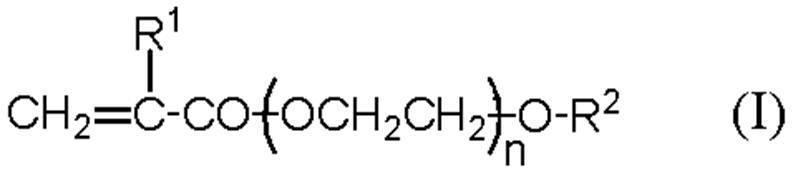
nは1~50の整数、好ましくは2~30の整数、より好ましくは2~10の整数である。
R2は水素原子又は1価の炭化水素基であり、例えば、炭素数1~50の炭化水素基であることが好ましく、炭素数1~25の炭化水素基であることがより好ましく、炭素数1~12の炭化水素基であることが更に好ましい。炭化水素基の炭素数が50以下であれば、電解液に対する十分な耐膨潤性を得ることができる傾向にある。ここで、炭化水素基としては、例えば、アルキル基及びフェニル基が好ましい。R2は、特に、炭素数1~12のアルキル基又はフェニル基であることが好ましい。このアルキル基は、直鎖及び分岐鎖のいずれであってもよい。R2がアルキル基又はフェニル基である場合、アルキル基又はフェニル基が有する水素原子は、フッ素原子、塩素原子、臭素原子、ヨウ素原子等のハロゲン原子、窒素原子含有基、リン原子含有基、酸素原子含有基、芳香族基、炭素数3~10のシクロアルキル基などで置換されていてもよい。
式(II)で表される単量体としては、特に制限されない。

R4は、炭素数4~100、好ましくは炭素数4~50、より好ましくは炭素数6~30、更に好ましくは炭素数8~15のアルキル基である。アルキル基の炭素数が4以上であれば、電極が十分な可撓性を示す傾向にあり、アルキル基の炭素数が100以下であれば、電解液に対する十分な耐膨潤性を得ることができる傾向にある。R4を構成するアルキル基は、直鎖及び分岐鎖のいずれであってもよい。また、R4を構成するアルキル基が有する水素原子は、フッ素原子、塩素原子、臭素原子、ヨウ素原子等のハロゲン原子、窒素原子含有基、リン原子含基、酸素原子含有基、芳香族基、炭素数3~10のシクロアルキル基などで置換されていてもよい。R4を構成するアルキル基としては、直鎖又は分岐鎖の飽和アルキル基の他、フルオロアルキル基、クロロアルキル基、ブロモアルキル基、ヨウ化アルキル基等のハロゲン化アルキル基などが挙げられる。
カルボキシ基含有単量体としては、特に制限されない。カルボキシ基含有単量体としては、アクリル酸、メタクリル酸等のアクリル系カルボキシ基含有単量体、クロトン酸等のクロトン系カルボキシ基含有単量体、マレイン酸及びその無水物等のマレイン系カルボキシ基含有単量体、イタコン酸及びその無水物等のイタコン系カルボキシ基含有単量体、シトラコン酸及びその無水物等のシトラコン系カルボキシ基含有単量体などが挙げられる。これらの中では、電極の柔軟性及び接着性の観点から、アクリル酸が好ましい。これらのカルボキシル基含有単量体は、1種を単独で又は2種以上を組み合わせて用いることができる。
カルボキシ基含有単量体を使用する場合、カルボキシ基含有単量体由来の構造単位の含有率は、結着材の全量に対して、0.1質量%~20質量%が好ましく、1質量%~10質量%がより好ましく、2質量%~6質量%が更に好ましい。
ニトリル基含有単量体由来の構造単位を含む樹脂は、上記ニトリル基含有単量体由来の構造単位と、式(I)で表される単量体由来の構造単位及び式(II)で表される単量体由来の構造単位からなる群より選択される少なくとも1つの構造単位と、カルボキシ基含有単量体由来の構造単位との他、これらの単量体とは異なる他の単量体の構造単位を適宜組み合わせることもできる。他の単量体としては、特に制限されない。他の単量体としては、メチル(メタ)アクリレート、エチル(メタ)アクリレート、プロピル(メタ)アクリレート等の短鎖(メタ)アクリル酸エステル、塩化ビニル、臭化ビニル、塩化ビニリデン等のハロゲン化ビニル化合物、スチレン、α-メチルスチレン、スチレンスルホン酸ナトリウム等のスチレン化合物、マレイミド、N-フェニルマレイミド等のイミド化合物、(メタ)アクリルアミド等のアミド化合物、酢酸ビニル、(メタ)アリルスルホン酸ナトリウム、(メタ)アリルオキシベンゼンスルホン酸ナトリウム、2-アクリルアミド-2-メチルプロパンスルホン酸及びその塩などが挙げられる。なお、「(メタ)アクリルアミド」はアクリルアミド又はメタクリルアミドを意味し、「(メタ)アリル」はアリル又はメタリルを意味する。これらの他の単量体は、1種を単独で又は2種以上を組み合わせて用いることができる。
ニトリル基含有単量体由来の構造単位を含む樹脂が、ニトリル基含有単量体由来の構造単位と、カルボキシ基含有単量体由来の構造単位と、式(I)で表される単量体由来の構造単位及び式(II)で表される単量体由来の構造単位からなる群より選択される少なくとも1つの構造単位とを含む場合、ニトリル基含有単量体由来の構造単位と、カルボキシ基含有単量体由来の構造単位と、式(I)で表される単量体由来の構造単位及び式(II)で表される単量体由来の構造単位からなる群より選択される少なくとも1つの構造単位とのモル比は、例えば、ニトリル基含有単量体由来の構造単位1モルに対して、カルボキシ基含有単量体由来の構造単位が好ましくは0.01モル~0.2モル、より好ましくは0.02~0.1モル、更に好ましくは0.03モル~0.06モルであり、式(I)又は式(II)で表される単量体由来の構造単位の合計が好ましくは0.001モル~0.2モル、より好ましくは0.003モル~0.05モル、更に好ましくは0.005モル~0.03モルである。カルボキシ基含有単量体由来の構造単位が0.01モル~0.2モルであり、式(I)又は式(II)で表される単量体由来の構造単位の合計が0.001モル~0.2モルであれば、集電体、特に銅箔を用いた集電体との接着性及び電解液に対する耐膨潤性に優れ、電極の柔軟性及び可撓性が良好となる傾向にある。
本開示のリチウムイオン二次電池用電極の電流遮断温度は、70℃~160℃に設定することが好ましく、90℃~120℃に設定することがより好ましい。電流遮断温度を70℃~160℃に設定すれば、電池自体又は電池が装着された各種機器に異常が発生したときに電流を遮断して発熱を抑制し、更に電池から各種機器への電力の供給等を停止できるので、非常に高い安全性が得られる。また、電流遮断温度を90℃~120℃に設定すれば、通常使用時の誤作動がなく、過充電等の異常時に電流を確実に遮断できるという利点が得られる。上記のような電流遮断温度は、ポリオレフィン粒子の融点(Tm)に依存する。電流遮断温度を90℃~120℃に設定する場合は、ポリオレフィン粒子としてポリエチレン粒子を用いることが好ましい。
なお、上記の電流遮断温度は、電池の25℃における直流抵抗に対して、直流抵抗上昇率が110%以上となる温度とする。
本開示のリチウムイオン二次電池は、前述したリチウムイオン二次電池用正極及びリチウムイオン二次電池用電極からなる群より選択される少なくとも1つの電極を備える。本開示のリチウムイオン二次電池は、前述したリチウムイオン二次電池用正極又はリチウムイオン二次電池用電極以外は、従来のリチウムイオン二次電池と同様の構成を採ることができる。例えば、本開示のリチウムイオン二次電池は、正極、負極、絶縁層、及び非水電解質を含む。
絶縁層(以下、セパレータという場合もある)は、正極と負極との間に介在するように設けられ、正極と負極とを絶縁する。絶縁層には、無機多孔質膜等のイオン透過性を有するものを使用できる。セパレータとしては、リチウムイオン二次電池の分野で常用されるものを使用でき、例えば、樹脂製多孔質シートが挙げられる。樹脂製多孔質シートを構成する樹脂としては、ポリエチレン、ポリプロピレン等のポリオレフィン、ポリアミド、ポリアミドイミド、ポリエステルなどが挙げられる。樹脂製多孔質シートには、不織布、織布等も含まれる。これらの中でも、内部に形成される空孔の径が0.05μm~0.15μm程度である多孔質シートが好ましい。このような多孔質シートは、イオン透過性、機械的強度、及び絶縁性を高い水準で兼ね備えている。また、多孔質シートの厚さは、特に制限されないが、0.5μm~30μmであることが好ましく、1μm~20μmであることがより好ましい。
非水電解質としては、例えば、液状非水電解質、ゲル状非水電解質、及び固体状電解質(例えば、高分子固体電解質)が挙げられる。液状非水電解質は、溶質(支持塩)と非水溶媒とを含み、更に必要に応じて各種添加剤を含む。溶質は通常非水溶媒中に溶解する。液状非水電解質は、例えば、絶縁層に含浸される。
また、電池特性をより向上できる観点から、非水溶媒にビニレンカーボネート(VC)を含有することが好ましい。
ビニレンカーボネート(VC)を含有する場合の含有率は、非水溶媒全量に対して、0.1質量%~2質量%が好ましく、0.2質量%~1.5質量%がより好ましい。
本発明をコイン型電池に適用した実施の形態について説明する。
コイン型電池は、例えば、次のようにして作製できる。まず、正極と負極とをコイン外装缶よりも小さい円形に切断する。正極、絶縁層、及び負極を、この順番に積層した積層体を作製し、その状態でコイン外装缶内に収容し、非水電解質をコイン外装缶内に注液後、コイン外装缶を密封する。これにより、リチウムイオン二次電池が得られる。
ラミネート型のリチウムイオン二次電池は、例えば、次のようにして作製できる。まず、正極と負極とを角形に切断し、それぞれの電極にタブを溶接して正負極端子を作製する。正極、絶縁層、及び負極をこの順番に積層した積層体を作製し、その状態でアルミニウム製のラミネートパック内に収容し、正負極端子をアルミラミネートパックの外に出し密封する。次いで、非水電解質をアルミラミネートパック内に注液し、アルミラミネートパックの開口部を密封する。これにより、リチウムイオン二次電池が得られる。
18650型のリチウムイオン二次電池10は、例えば、次のようにして作製できる。まず、正極と負極とを帯状に切断し、それぞれの電極にタブを溶接し正負極端子を作製する。帯状の正極11及び負極12がセパレータ13を介して断面渦巻状に捲回された電極群14を作製し、その状態でニッケルメッキが施されたスチール製の有底円筒状の電池容器15に収容する。電極群14の上端面には、一端部を正極11に固定されたアルミニウム製でリボン状の正極タブ端子が導出されている。正極タブ端子の他端部は、電極群14の上側に配置され正極外部端子となる円盤状の電池蓋の下面に超音波溶接で接合されている。一方、電極群14の下端面には、一端部を負極12に固定された銅製でリボン状の負極タブ端子が導出されている。負極タブ端子の他端部は、電池容器15の内底部に抵抗溶接で接合されている。したがって、正極タブ端子及び負極タブ端子は、それぞれ電極群14の両端面の互いに反対側に導出されている。なお、電極群14の外周面全周には、絶縁被覆が施されている。次いで、非水電解質を電池容器15内に注液し、電池蓋を絶縁性の樹脂製ガスケットを介して電池容器15の上部にカシメ固定する。このため、リチウムイオン二次電池10の内部は密封されている。
本開示のリチウムイオン二次電池は、高い安全性を有し、しかも高出力であり、従来の非水電解質二次電池と同様の用途に好適に使用できる。特に、携帯電話、ノート型パソコン、携帯用情報端末、電子辞書、ゲーム機器等の各種携帯用電子機器類の電源として好適に使用できる。このような用途に利用する場合、充電時に万が一過充電状態になっても、発熱が抑制されるので、電池の高温化、膨れ等が確実に防止される。また、本開示のリチウムイオン二次電池は、電力貯蔵用、電気自動車、ハイブリット自動車等の輸送機器用などの用途にも応用可能である。
(1)正極の作製
LiMn2O4(正極活物質、三井金属鉱業(株)製)と、アセチレンブラック(導電性材料、商品名:HS-100、平均粒径48nm(電気化学工業(株)カタログ値)、電気化学工業(株)製)と、ポリエチレン粒子(絶縁性のポリオレフィン粒子、商品名:ケミパール(登録商標)W410、平均粒径9.5μm(三井化学(株)カタログ値)、融点110℃(三井化学(株)カタログ値))、三井化学(株)製、を乾燥し粉末状にしたもの)と、ポリフッ化ビニリデン(PVDF)溶液(結着材、固形分12質量%)とを、固形分の質量比(正極活物質:導電性材料:絶縁性のポリオレフィン粒子:結着材)が92.0:4.5:2.5:1.0になるように混合し、N-メチル-2-ピロリドン(溶媒、和光純薬工業(株)製、特級)中に十分に分散させ、正極合剤ペーストを調製した。この正極合剤ペーストを厚さ17μmのアルミニウム箔(正極集電体、三菱アルミニウム(株)製)の片面に塗布し、60℃で5時間乾燥後、圧延して、厚さ75μm、塗布量200g/m2、合剤密度2.55g/cm3の正極活物質層を形成し、正極Aを作製した。正極Aを120℃に設定した恒温槽で15分間加熱し、正極Bを得た。
図3に、実施例1で得られた正極活物質層(正極A)表面の走査型電子顕微鏡写真を示す。
図4に、実施例1で得られた正極活物質層(正極B)表面の走査型電子顕微鏡写真を示す。
非晶質炭素(負極活物質)と、アセチレンブラック(導電性材料、商品名:HS-100、平均粒径48nm(電気化学工業(株)カタログ値)、電気化学工業(株)製)と、ポリフッ化ビニリデン(PVDF)溶液(結着材、固形分12質量%)とを、固形分の質量比(負極活物質:導電性材料:結着材)が87.6:4.8:7.6になるように混合し、N-メチル-2-ピロリドン(溶媒、和光純薬工業(株)製、特級)中に十分に分散させ、負極合剤ペーストを調製した。この負極合剤ペーストを厚さ10μmの銅箔(負極集電体)に塗布し、100℃で30分間乾燥後、圧延して、厚さ62μm、塗布量60g/m2、合剤密度0.97g/cm3の負極活物質層を形成し、負極を作製した。
作製した正極A及び正極Bを、それぞれ直径14mmの円形に切断し、評価用正極を得た。作製した負極を直径16mmの円形に切断し、評価用負極を得た。ポリエチレン微多孔膜からなるセパレータ(商品名:ハイポア、旭化成イーマテリアルズ(株)製、直径19mmの円形に切断したもの)を介し、正負極を活物質層が対向するように重ね合わせた積層体を作製した。この積層体をコイン外装缶(東洋システム(株)製)に入れ、電解液(1MのLiPF6を含むエチレンカーボネート/ジメチルカーボネート=3/7混合溶液(体積比)に対してビニレンカーボネートを0.5モル%添加したもの)を1mL添加後、コイン外装缶を密閉し、電極評価用電池を作製した。
正極合剤ペーストの固形分の質量比(正極活物質:導電性材料:絶縁性のポリオレフィン粒子:結着材)を90.0:4.5:4.5:1.0になるように混合した以外は、実施例1と同様にして、電極評価用電池を作製した。
正極合剤ペーストの固形分の質量比(正極活物質:導電性材料:絶縁性のポリオレフィン粒子:結着材)を88.0:4.5:6.5:1.0になるように混合した以外は、実施例1と同様にして、電極評価用電池を作製した。
正極合剤ペーストの固形分の質量比(正極活物質:導電性材料:絶縁性のポリオレフィン粒子:結着材)を84.5:4.5:10.0:1.0になるように混合した以外は、実施例1と同様にして、電極評価用電池を作製した。
絶縁性のポリオレフィン粒子として、ポリエチレン粒子(絶縁性のポリオレフィン粒子、商品名:ケミパール(登録商標)W410、平均粒径9.5μm(三井化学(株)カタログ値)、融点110℃(三井化学(株)カタログ値)を乾燥し粉末状にしたもの)の代わりにポリエチレン粒子(絶縁性のポリオレフィン粒子、商品名:ケミパール(登録商標)W4005、平均粒径0.6μm(三井化学(株)カタログ値)、融点110℃(三井化学(株)カタログ値)を乾燥し粉末状にしたもの)を使用した以外は、実施例2と同様にして、電極評価用電池を作製した。
結着材として、ポリフッ化ビニリデン溶液の代わりにポリアクリロニトリル骨格にアクリル酸及び直鎖エーテル基を付加した共重合体(結着材、日立化成(株)製、商品名:LSR7)を使用した以外は、実施例2と同様にして、電極評価用電池を作製した。
正極合剤ペーストの固形分の質量比(正極活物質:導電性材料:絶縁性のポリオレフィン粒子:結着材)を90.0:4.5:0:5.5になるように混合した以外は、実施例1と同様にして、電極評価用電池を作製した。
(1)導電性のポリオレフィン粒子の作製
ポリエチレン粒子(絶縁性のポリオレフィン粒子、商品名:ケミパール(登録商標)W410、平均粒径9.5μm(三井化学(株)カタログ値)、融点110℃(三井化学(株)カタログ値)を乾燥し粉末状にしたもの)とアセチレンブラック(導電性粒子、商品名:HS-100、平均粒径48nm(電気化学工業(株)カタログ値)、電気化学工業(株)製)とを質量比で0.5/0.5になるよう混練・押出成形評価試験装置(製品名:ラボプラストミル、(株)東洋精機製作所製)で十分に混練した後、粉砕し、導電性のポリオレフィン粒子を作製した。
LiMn2O4(正極活物質、三井金属鉱業(株)製)と、導電性のポリオレフィン粒子と、ポリフッ化ビニリデン(PVDF)溶液(結着材、固形分12質量%)とを、固形分の質量比(正極活物質:導電性のポリオレフィン粒子:結着材)が90.0:9.0:1.0になるように混合し、N-メチル-2-ピロリドン(溶媒、和光純薬工業(株)製、特級)中に十分に分散させ、正極合剤ペーストを調製した。この正極合剤ペーストを厚さ17μmのアルミニウム箔(正極集電体、三菱アルミニウム(株)製)の片面に塗布し、60℃で5時間乾燥後、圧延して、厚さ75μm、塗布量200g/m2、合剤密度2.55g/cm3の正極活物質層を形成し、正極Aを作製した。正極Aを120℃に設定した恒温槽で15分間加熱し、正極Bを得た。
非晶質炭素(負極活物質)と、アセチレンブラック(導電性材料、商品名:HS-100、平均粒径48nm(電気化学工業(株)カタログ値)、電気化学工業(株)製)と、ポリフッ化ビニリデン(PVDF)溶液(結着材、固形分12質量%)とを、固形分の質量比(負極活物質:導電性材料:結着材)が87.6:4.8:7.6になるように混合し、N-メチル-2-ピロリドン(溶媒、和光純薬工業(株)製、特級)中に十分に分散させ、負極合剤ペーストを調製した。この負極合剤ペーストを厚さ10μmの銅箔(負極集電体)に塗布し、100℃で30分間乾燥後、圧延して、厚さ62μm、塗布量60g/m2、合剤密度0.97g/cm3の負極活物質層を形成し、負極を作製した。
作製した正極A及び正極Bを、それぞれ直径14mmの円形に切断し、評価用正極を得た。作製した負極を直径16mmの円形に切断し、評価用負極を得た。ポリエチレン微多孔膜からなるセパレータ(商品名:ハイポア、旭化成イーマテリアルズ(株)製、直径19mmの円形に切断したもの)を介し、正負極を活物質層が対向するように重ね合わせた積層体を作製した。この積層体をコイン外装缶(東洋システム(株)製)に入れ、電解液(1MのLiPF6を含むエチレンカーボネート/ジメチルカーボネート=3/7混合溶液(体積比)に対してビニレンカーボネートを0.5モル%添加したもの)を1mL添加後、コイン外装缶を密閉し、電極評価用電池を作製した。
(1)放電特性の評価
実施例1~6及び比較例1~2で正極Aを使用した電極評価用電池を25℃に設定した恒温槽内に入れ、充放電装置(東洋システム(株)製、商品名:TOSCAT-3200)を用いて25℃で、以下の条件で充放電した。4.2V、0.5Cで定電流定電圧(CCCV)充電(充電終止条件:0.01C)を行った後、0.5Cで2.7Vまで定電流(CC)放電を行い、放電容量を測定し、放電特性とした。
実施例1~6及び比較例1~2で正極Aを使用した電極評価用電池を25℃に設定した恒温槽内に入れ、充放電装置(東洋システム(株)製、商品名:TOSCAT-3200)を用いて25℃で、以下の条件で充放電した。4.2V、0.5Cで定電流定電圧(CCCV)充電(充電終止条件:0.01C)を行った後、0.5Cで2.7Vまで定電流(CC)放電を行い、放電容量を測定した。次いで、4.2V、0.5Cで定電流定電圧(CCCV)充電(充電終止条件:0.01C)を行った後、3.0Cで2.7Vまで定電流(CC)放電を行い、下記の式から算出される値を放電レート特性とした。なお、放電電流値を示すCとは“電流値(A)/電池容量(Ah)”を意味する。
放電レート特性(%)=(3Cでの放電容量/0.5Cでの放電容量)×100
実施例1~6及び比較例1~2で正極Aを使用した電極評価用電池を25℃に設定した恒温槽内に入れ、25℃での直流抵抗(DCR)を測定し、これを初期抵抗とした。次に、実施例1~6及び比較例1~2で正極Bを使用した電極評価用電池を25℃に設定した恒温槽内に入れ、25℃での直流抵抗(DCR)を測定し、これを加熱後抵抗とした。初期抵抗及び加熱後抵抗から下記式に従って抵抗上昇率(%)を算出し、PTC機能の指標とした。
抵抗上昇率(%)=(加熱後抵抗/初期抵抗)×100
なお、直流抵抗(DCR)は、下記の式より算出した。

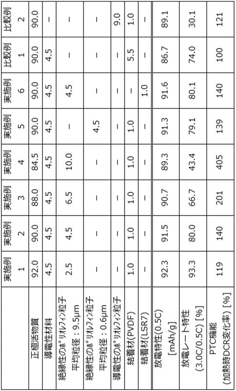
加えて、実施例1~4のPTC機能は、絶縁性のポリオレフィン粒子の含有量が多くなるほど向上しており、絶縁性のポリオレフィン粒子の含有量が多くなるほど安全な電池が得られることが示唆される。
PTC機能が確認された120℃という温度は、セパレータのシャットダウン温度(135℃)よりも低い温度である。このことから、実施例1~6の電池が、過充電等による発熱時に、セパレータがシャットダウンする前に、抵抗を上昇させて電流を遮断し、それにより発熱を抑制できることが示唆される。これにより、実施例1~6の電池が優れた安全性を有することが実証される。
比較例2は、ポリオレフィンと導電性材料とをあらかじめ混合した導電性のポリオレフィン粒子を使用した電極評価用電池である。比較例2の正極活物質層中のポリオレフィン及び導電性材料の含有量は実施例2と同等であるにも関わらず、比較例2の電極評価用電池はレート特性に乏しい。これは、導電性材料がポリオレフィン中に存在しているために、導電性材料としての効果が低下しているためである。
ニトリル基含有単量体由来の構造単位を含む樹脂(樹脂A)の合成
撹拌機、温度計、冷却管、及び窒素ガス導入管を装備した3リットルのセパラブルフラスコに、精製水1804gを仕込み、窒素ガス通気量200mL/分の条件下、撹拌しながら74℃まで昇温した後、窒素ガスの通気を止めた。次いで、重合開始剤の過硫酸アンモニウム0.968gを精製水76gに溶かした水溶液を添加し、直ちに、ニトリル基含有単量体のアクリロニトリル183.8g、カルボキシ基含有単量体のアクリル酸9.7g(アクリロニトリル1モルに対して0.039モルの割合)、及び式(I)で表される単量体のメトキシトリエチレングリコールアクリレート(新中村化学工業(株)製、商品名:NKエステルAM-30G)6.5g(アクリロニトリル1モルに対して0.0085モルの割合)の混合液を、系の温度を74℃±2℃に保ちながら、2時間かけて滴下した。続いて、懸濁した反応系に、過硫酸アンモニウム0.25gを精製水21.3gに溶かした水溶液を追加添加し、84℃まで昇温した後、系の温度を84℃±2℃に保ちながら、2.5時間反応を進めた。その後、1時間かけて40℃まで冷却した後、撹拌を止めて一晩室温(25℃)で放冷し、ニトリル基含有単量体由来の構造単位を含む樹脂が沈殿した反応液を得た。この反応液を吸引濾過し、回収した湿潤状態の沈殿を精製水1800gで3回洗浄した後、80℃で10時間真空乾燥して、ニトリル基含有単量体由来の構造単位を含む樹脂Aを得た。
ニトリル基含有単量体由来の構造単位を含む樹脂(樹脂B)の合成
撹拌機、温度計、及び冷却管を装着した1.0リットルのセパラブルフラスコ内に、窒素雰囲気下、ニトリル基含有単量体のアクリロニトリル(和光純薬工業(株)製)45.0g、式(II)で表される単量体のラウリルアクリレート(Aldrich社製)5.0g(アクリロニトリル1モルに対して0.0232モルの割合)、重合開始剤の過硫酸カリウム(和光純薬工業(株)製)1.175mg、連鎖移動剤のα-メチルスチレンダイマー(和光純薬工業(株)製)135mg、精製水(和光純薬工業(株)製)450mLを加えて反応液を調製した。反応液を激しく撹拌しながら、60℃で3時間撹拌した後、80℃で3時間撹拌した。室温に冷却後、反応液を吸引濾過し、析出した樹脂を濾別した。濾別した樹脂を精製水(和光純薬工業(株)製)300mL及びアセトン(和光純薬工業(株)製)300mLで順に洗浄した。洗浄した樹脂を60℃、1torr(133Pa)の真空管乾燥機で24時間乾燥して、ニトリル基含有単量体由来の構造単位を含む樹脂Bを得た。
(1)正極の作製
LiMn2O4(正極活物質、三井金属鉱業(株)製)と、アセチレンブラック(導電性材料、商品名:HS-100、平均粒径48nm(電気化学工業(株)カタログ値)、電気化学工業(株)製)と、合成例1で作製した樹脂Aと、ポリエチレン粒子(ポリオレフィン粒子、商品名:ケミパール(登録商標)W410、平均粒径9.5μm(三井化学(株)カタログ値)、融点110℃(三井化学(株)カタログ値)、三井化学(株)製、水分散されているものを乾燥し粉末状にしたもの)とを、固形分の質量比(正極活物質:導電性材料:樹脂A:ポリオレフィン粒子)が90.0:4.5:1.0:4.5になるように混合し、N-メチル-2-ピロリドン(溶媒、和光純薬工業(株)製、特級)中に十分に分散させ、正極合剤ペーストを調製した。この正極合剤ペーストを厚さ17μmのアルミニウム箔(正極集電体、三菱アルミニウム(株)製)の片面に塗布し、60℃で5時間乾燥後、圧延して、厚さ75μm、塗布量200g/m2、合剤密度2.55g/cm3の正極活物質層を形成し、正極Aを作製した。正極Aを120℃に設定した恒温槽で15分間加熱し、正極Bを得た。次いで、正極Aを160℃に設定した恒温槽で15分間加熱し、正極Cを得た。
非晶質炭素(負極活物質)と、アセチレンブラック(導電性材料、商品名:HS-100、平均粒径48nm(電気化学工業(株)カタログ値)、電気化学工業(株)製)、ポリフッ化ビニリデン(PVDF)溶液(結着材、固形分12質量%)とを、固形分の質量比(負極活物質:導電性材料:結着材)が87.6:4.8:7.6になるように混合し、N-メチル-2-ピロリドン(溶媒、和光純薬工業(株)製、特級)中に十分に分散させ、負極合剤ペーストを調製した。この負極合剤ペーストを厚さ10μmの銅箔(負極集電体)に塗布し、100℃で30分間乾燥後、圧延して、厚さ62μm、塗布量60g/m2、合剤密度0.97g/cm3の負極活物質層を形成し、負極を作製した。
作製した正極A、正極B、及び正極Cを、それぞれ直径14mmの円形に切断し、評価用正極を得た。作製した負極を直径16mmの円形に切断し、評価用負極を得た。ポリエチレン微多孔膜からなるセパレータ(商品名:ハイポア、旭化成イーマテリアルズ(株)製、直径19mmの円形に切断したもの)を介し、正負極を活物質層が対向するよう重ね合わせた積層体を作製した。この積層体をコイン外装缶(東洋システム(株)製)に入れ、電解液(1MのLiPF6を含むエチレンカーボネート/ジメチルカーボネート=3/7混合溶液(体積比)に混合溶液全量に対してビニレンカーボネートを0.5モル%添加したもの)を1mL添加後、コイン外装缶を密閉し、電極評価用電池を作製した。
正極合剤ペーストの固形分の質量比(正極活物質:導電性材料:樹脂A:ポリオレフィン粒子)を91.0:4.5:1.0:3.5になるように混合した以外は、実施例7と同様にして電極評価用電池を作製した。
正極合剤ペーストの固形分の質量比(正極活物質:導電性材料:樹脂A:ポリオレフィン粒子)を92.0:4.5:1.0:2.5になるように混合した以外は、実施例7と同様にして電極評価用電池を作製した。
ニトリル基含有単量体由来の構造単位を含む樹脂を樹脂Bに変更した以外は、実施例1と同様にして電極評価用電池を作製した。
正極合剤ペーストの固形分の質量比(正極活物質:導電性材料:樹脂B:ポリオレフィン粒子)を91.0:4.5:1.0:3.5になるように混合した以外は、実施例10と同様にして電極評価用電池を作製した。
正極合剤ペーストの固形分の質量比(正極活物質:導電性材料:樹脂B:ポリオレフィン粒子)を92.0:4.5:1.0:2.5になるように混合した以外は、実施例10と同様にして電極評価用電池を作製した。
ポリオレフィン粒子として、平均粒径9.5μmのポリエチレン粒子(ポリオレフィン粒子、商品名:ケミパール(登録商標)W410、平均粒径9.5μm(三井化学(株)カタログ値)、三井化学(株)製、水分散されているものを乾燥し粉末状にしたもの)の代わりに、平均粒径0.6μmのポリエチレン粒子(ポリオレフィン粒子、商品名:ケミパール(登録商標)W4005、平均粒径0.6μm(三井化学(株)カタログ値)、三井化学(株)製、水分散されているものを乾燥し粉末状にしたもの)を使用した以外は、実施例7と同様にして電極評価用電池を作製した。
ポリオレフィン粒子として、ポリエチレン粒子(ポリオレフィン粒子、商品名:ケミパール(登録商標)W410、平均粒径9.5μm(三井化学(株)カタログ値)、三井化学(株)製、水分散されているものを乾燥し粉末状にしたもの)の代わりに、ポリプロピレン粒子(ポリオレフィン粒子、商品名:ケミパール(登録商標)WP100、平均粒径1.0μm(三井化学(株)カタログ値)、融点148℃(三井化学(株)カタログ値)、三井化学(株)製、水分散されているものを乾燥し粉末状にしたもの)を使用した以外は、実施例7と同様にして電極評価用電池を作製した。
正極合剤ペーストの固形分の質量比(正極活物質:導電性材料:樹脂A:ポリオレフィン粒子)を90.0:4.5:5.5:0になるように混合した以外は、実施例7と同様にして電極評価用電池を作製した。
正極合剤ペーストの固形分の質量比(正極活物質:導電性材料:樹脂B:ポリオレフィン粒子)を90.0:4.5:5.5:0になるように混合した以外は、実施例10と同様にして電極評価用電池を作製した。
結着材として、樹脂Aの代わりにポリフッ化ビニリデン(ニトリル基含有単量体由来の構造単位を含まない樹脂)を使用した以外は、比較例3と同様にして電極評価用電池を作製した。
(1)正極活物質層の密着強度の評価
実施例7~14及び比較例3~5で得られた正極Aを10mm×50mmにカットした試験片を準備し、精密万能試験機(商品名:AGS-X、(株)島津製作所製)を用いて、剥離速度:100mm/分、測定距離:25mm、室温:25℃での180度剥離強度を測定し、正極活物質層の密着強度とした。
実施例7~14及び比較例3~5で正極Aを使用した電極評価用電池を25℃に設定した恒温槽内に入れ、充放電装置(東洋システム(株)製、商品名:TOSCAT-3200)を用いて25℃で、以下の条件で充放電した。4.2V、0.5Cで定電流定電圧(CCCV)充電(充電終止条件:0.01C)を行った後、0.5Cで2.7Vまで定電流(CC)放電を行い、放電容量を測定した。次いで、4.2V、0.5Cで定電流定電圧(CCCV)充電(充電終止条件:0.01C)を行った後、3.0Cで2.7Vまで定電流(CC)放電を行い、下記の式から算出される値を放電レート特性とした。
放電レート特性(%)=(3Cでの放電容量/0.5Cでの放電容量)×100
実施例7~14及び比較例3~5で正極Bを使用した電極評価用電池について、上記(2)と同様の方法で、120℃加熱後における放電レート特性を評価した。
実施例7~14及び比較例3~5で正極Cを使用した電極評価用電池について、上記(2)と同様の方法で、160℃加熱後における放電レート特性を評価した。
実施例7~14及び比較例3~5で正極Aを使用した電極評価用電池を25℃に設定した恒温槽内に入れ、25℃での直流抵抗(DCR)を測定し、これを初期抵抗とした。次に、実施例7~14及び比較例3~5で正極Bを使用した電極評価用電池を25℃に設定した恒温槽内に入れ、25℃での直流抵抗(DCR)を測定し、これを120℃加熱後抵抗とした。初期抵抗及び120℃加熱後抵抗から下記式に従って抵抗上昇率(%)を算出し、120℃でのPTC機能の指標とした。
抵抗上昇率(%)=(120℃加熱後抵抗/初期抵抗)×100
なお、直流抵抗(DCR)は、前述した式より算出した。
実施例7~14及び比較例3~5で正極Aを使用した電極評価用電池を25℃に設定した恒温槽内に入れ、25℃での直流抵抗(DCR)を測定し、これを初期抵抗とした。次に、実施例7~14及び比較例3~5で正極Cを使用した電極評価用電池を25℃に設定した恒温槽内に入れ、25℃での直流抵抗(DCR)を測定し、これを160℃加熱後抵抗とした。初期抵抗及び160℃加熱後抵抗から下記式に従って抵抗上昇率(%)を算出し、160℃でのPTC機能の指標とした。
抵抗上昇率(%)=(160℃加熱後抵抗/初期抵抗)×100
なお、直流抵抗(DCR)は、前述した式より算出した。
実施例7~14及び比較例3~5で正極Aを使用した電極評価用電池を25℃に設定した恒温槽内に入れ、25℃でのサイクル特性を、充放電装置(東洋システム(株)製、商品名:TOSCAT-3200)を用いて以下の充放電条件で測定し、サイクル特性とした。4.2V、1Cで定電流定電圧(CCCV)充電(充電終止条件:0.01C)を行った後、1Cで2.7Vまで定電流(CC)放電を行い、下記の式から算出される値を50サイクル後の放電容量維持率として評価した。
50サイクル後の放電容量維持率(%)=(50サイクル目の放電容量/1サイクル目の放電容量)×100

本明細書に記載された全ての文献、特許出願、及び技術規格は、個々の文献、特許出願、及び技術規格が参照により取り込まれることが具体的かつ個々に記された場合と同程度に、本明細書中に参照により取り込まれる。
Claims (8)
- 絶縁性のポリオレフィン粒子と導電性材料とを含有する正極活物質層を備えるリチウムイオン二次電池用正極。
- 前記絶縁性のポリオレフィン粒子の含有率が、前記正極活物質層の総量に対して、0.1質量%~10質量%である請求項1に記載のリチウムイオン二次電池用正極。
- 前記正極活物質層に含有される前記絶縁性のポリオレフィン粒子と前記導電性材料との質量比(絶縁性のポリオレフィン粒子/導電性材料)が、0.15/0.85~0.85/0.15である請求項1又は請求項2に記載のリチウムイオン二次電池用正極。
- 前記絶縁性のポリオレフィン粒子の平均粒径が0.1μm~30μmである請求項1~請求項3のいずれか1項に記載のリチウムイオン二次電池用正極。
- ポリオレフィン粒子とニトリル基含有単量体由来の構造単位を含む樹脂とを含有する電極活物質層を備えるリチウムイオン二次電池用電極。
- 前記ポリオレフィン粒子の平均粒径が0.1μm~30μmである請求項5に記載のリチウムイオン二次電池用電極。
- 前記ポリオレフィン粒子の含有率が、前記電極活物質層の総量に対して、0.1質量%~10質量%である請求項5又は請求項6に記載のリチウムイオン二次電池用電極。
- 請求項1~請求項4のいずれか1項に記載のリチウムイオン二次電池用正極及び請求項5~請求項7のいずれか1項に記載のリチウムイオン二次電池用電極からなる群より選択される少なくとも1つの電極を備えるリチウムイオン二次電池。
Priority Applications (4)
| Application Number | Priority Date | Filing Date | Title |
|---|---|---|---|
| KR1020177024900A KR20170113645A (ko) | 2015-02-10 | 2016-02-02 | 리튬 이온 이차 전지용 정극, 리튬 이온 이차 전지용 전극 및 리튬 이온 이차 전지 |
| US15/549,579 US10763509B2 (en) | 2015-02-10 | 2016-02-02 | Positive electrode for lithium ion secondary battery, electrode for lithium ion secondary battery, electrode active material layer including polyolefin particles, and lithium ion secondary battery |
| JP2016574748A JP6406363B2 (ja) | 2015-02-10 | 2016-02-02 | リチウムイオン二次電池用正極、リチウムイオン二次電池用電極、及びリチウムイオン二次電池 |
| CN201680009313.0A CN107251291B (zh) | 2015-02-10 | 2016-02-02 | 锂离子二次电池用正极、锂离子二次电池用电极和锂离子二次电池 |
Applications Claiming Priority (4)
| Application Number | Priority Date | Filing Date | Title |
|---|---|---|---|
| JP2015024611 | 2015-02-10 | ||
| JP2015-024611 | 2015-02-10 | ||
| JP2015024878 | 2015-02-12 | ||
| JP2015-024878 | 2015-02-12 |
Publications (1)
| Publication Number | Publication Date |
|---|---|
| WO2016129459A1 true WO2016129459A1 (ja) | 2016-08-18 |
Family
ID=56614334
Family Applications (1)
| Application Number | Title | Priority Date | Filing Date |
|---|---|---|---|
| PCT/JP2016/053094 Ceased WO2016129459A1 (ja) | 2015-02-10 | 2016-02-02 | リチウムイオン二次電池用正極、リチウムイオン二次電池用電極、及びリチウムイオン二次電池 |
Country Status (6)
| Country | Link |
|---|---|
| US (1) | US10763509B2 (ja) |
| JP (1) | JP6406363B2 (ja) |
| KR (1) | KR20170113645A (ja) |
| CN (1) | CN107251291B (ja) |
| TW (1) | TWI703764B (ja) |
| WO (1) | WO2016129459A1 (ja) |
Cited By (4)
| Publication number | Priority date | Publication date | Assignee | Title |
|---|---|---|---|---|
| JPWO2017138537A1 (ja) * | 2016-02-08 | 2018-07-05 | 日立化成株式会社 | バインダ樹脂組成物、バインダ樹脂組成物の製造方法、リチウムイオン二次電池電極形成用組成物、リチウムイオン二次電池電極形成用組成物の製造方法、リチウムイオン二次電池用電極、及びリチウムイオン二次電池 |
| JP2018120674A (ja) * | 2017-01-23 | 2018-08-02 | 日立化成株式会社 | エネルギーデバイス用電極及びエネルギーデバイス |
| CN110199409A (zh) * | 2017-01-23 | 2019-09-03 | 日立化成株式会社 | 能量装置用电极和能量装置 |
| JP2024526447A (ja) * | 2022-03-29 | 2024-07-18 | エルジー エナジー ソリューション リミテッド | 正極及びこれを含む電池 |
Families Citing this family (17)
| Publication number | Priority date | Publication date | Assignee | Title |
|---|---|---|---|---|
| CN107408700A (zh) * | 2015-03-18 | 2017-11-28 | 日立化成株式会社 | 粘合剂树脂组合物、锂离子二次电池用电极和锂离子二次电池 |
| JP6863288B2 (ja) * | 2015-11-19 | 2021-04-21 | 日本ゼオン株式会社 | リチウムイオン二次電池用電極 |
| CN106848194A (zh) * | 2016-12-20 | 2017-06-13 | 北京鼎能开源电池科技股份有限公司 | 一种安全型三元电池正极片的制造方法 |
| EP3671906B1 (en) * | 2017-09-29 | 2024-12-25 | GS Yuasa International Ltd. | Electrode and energy storage device |
| KR102259219B1 (ko) | 2018-07-03 | 2021-05-31 | 삼성에스디아이 주식회사 | 리튬 이차 전지 |
| KR102259218B1 (ko) | 2018-07-03 | 2021-05-31 | 삼성에스디아이 주식회사 | 리튬 이차 전지용 전극, 및 이를 포함하는 리튬 이차 전지 |
| KR102323950B1 (ko) | 2018-12-12 | 2021-11-08 | 삼성에스디아이 주식회사 | 리튬 이차 전지용 전극 및 이를 포함하는 리튬 이차 전지 |
| KR102492832B1 (ko) | 2019-05-03 | 2023-01-26 | 삼성에스디아이 주식회사 | 리튬 이차 전지 |
| KR102425515B1 (ko) | 2019-05-03 | 2022-07-25 | 삼성에스디아이 주식회사 | 리튬 이차 전지 |
| KR102425514B1 (ko) | 2019-05-03 | 2022-07-25 | 삼성에스디아이 주식회사 | 리튬 이차 전지 |
| KR102487628B1 (ko) | 2019-05-03 | 2023-01-12 | 삼성에스디아이 주식회사 | 리튬 이차 전지 |
| KR102425513B1 (ko) | 2019-05-03 | 2022-07-25 | 삼성에스디아이 주식회사 | 리튬 이차 전지 |
| KR102492831B1 (ko) | 2019-05-03 | 2023-01-26 | 삼성에스디아이 주식회사 | 리튬 이차 전지 |
| AU2021292254A1 (en) * | 2020-06-17 | 2023-02-09 | Grst Singapore Pte. Ltd. | Binder composition for secondary battery |
| CN111710826B (zh) * | 2020-08-20 | 2020-12-08 | 苏州清陶新能源科技有限公司 | 一种锂离子电池正极的制备方法 |
| WO2022141447A1 (zh) * | 2020-12-31 | 2022-07-07 | 宁德新能源科技有限公司 | 极片、电化学装置和电子装置 |
| KR20220111565A (ko) * | 2021-02-02 | 2022-08-09 | 삼성에스디아이 주식회사 | 리튬 이차 전지용 전극 및 이를 포함하는 리튬 이차 전지 |
Citations (6)
| Publication number | Priority date | Publication date | Assignee | Title |
|---|---|---|---|---|
| JP2004247292A (ja) * | 2003-01-21 | 2004-09-02 | Hitachi Chem Co Ltd | バインダー樹脂、合剤スラリー、非水電解液系二次電池の電極及び非水電解液系二次電池 |
| WO2006132474A1 (en) * | 2005-06-04 | 2006-12-14 | Ls Cable Ltd. | Ptc powder, lithium secondary battery having ptc powder and manufacturing method thereof |
| JP2009176599A (ja) * | 2008-01-25 | 2009-08-06 | Panasonic Corp | 非水電解質二次電池 |
| JP2010092719A (ja) * | 2008-10-08 | 2010-04-22 | Hitachi Chem Co Ltd | 非水電解液系エネルギーデバイス電極用接着添加剤、これを用いた非水電解液系エネルギーデバイス電極用バインダ樹脂組成物、これを用いた非水電解液系エネルギーデバイス電極、及び非水電解液系エネルギーデバイス |
| JP2011029079A (ja) * | 2009-07-28 | 2011-02-10 | Sharp Corp | 非水電解質二次電池 |
| JP2013105681A (ja) * | 2011-11-15 | 2013-05-30 | Toyota Motor Corp | 非水電解質二次電池とその製造方法 |
Family Cites Families (1)
| Publication number | Priority date | Publication date | Assignee | Title |
|---|---|---|---|---|
| JP3677975B2 (ja) | 1996-12-26 | 2005-08-03 | 三菱電機株式会社 | 電極及びこれを用いた電池 |
-
2016
- 2016-02-02 JP JP2016574748A patent/JP6406363B2/ja not_active Expired - Fee Related
- 2016-02-02 US US15/549,579 patent/US10763509B2/en not_active Expired - Fee Related
- 2016-02-02 KR KR1020177024900A patent/KR20170113645A/ko not_active Ceased
- 2016-02-02 WO PCT/JP2016/053094 patent/WO2016129459A1/ja not_active Ceased
- 2016-02-02 CN CN201680009313.0A patent/CN107251291B/zh not_active Expired - Fee Related
- 2016-02-15 TW TW105104321A patent/TWI703764B/zh not_active IP Right Cessation
Patent Citations (6)
| Publication number | Priority date | Publication date | Assignee | Title |
|---|---|---|---|---|
| JP2004247292A (ja) * | 2003-01-21 | 2004-09-02 | Hitachi Chem Co Ltd | バインダー樹脂、合剤スラリー、非水電解液系二次電池の電極及び非水電解液系二次電池 |
| WO2006132474A1 (en) * | 2005-06-04 | 2006-12-14 | Ls Cable Ltd. | Ptc powder, lithium secondary battery having ptc powder and manufacturing method thereof |
| JP2009176599A (ja) * | 2008-01-25 | 2009-08-06 | Panasonic Corp | 非水電解質二次電池 |
| JP2010092719A (ja) * | 2008-10-08 | 2010-04-22 | Hitachi Chem Co Ltd | 非水電解液系エネルギーデバイス電極用接着添加剤、これを用いた非水電解液系エネルギーデバイス電極用バインダ樹脂組成物、これを用いた非水電解液系エネルギーデバイス電極、及び非水電解液系エネルギーデバイス |
| JP2011029079A (ja) * | 2009-07-28 | 2011-02-10 | Sharp Corp | 非水電解質二次電池 |
| JP2013105681A (ja) * | 2011-11-15 | 2013-05-30 | Toyota Motor Corp | 非水電解質二次電池とその製造方法 |
Cited By (7)
| Publication number | Priority date | Publication date | Assignee | Title |
|---|---|---|---|---|
| JPWO2017138537A1 (ja) * | 2016-02-08 | 2018-07-05 | 日立化成株式会社 | バインダ樹脂組成物、バインダ樹脂組成物の製造方法、リチウムイオン二次電池電極形成用組成物、リチウムイオン二次電池電極形成用組成物の製造方法、リチウムイオン二次電池用電極、及びリチウムイオン二次電池 |
| JP2018120674A (ja) * | 2017-01-23 | 2018-08-02 | 日立化成株式会社 | エネルギーデバイス用電極及びエネルギーデバイス |
| CN110199409A (zh) * | 2017-01-23 | 2019-09-03 | 日立化成株式会社 | 能量装置用电极和能量装置 |
| EP3573140A4 (en) * | 2017-01-23 | 2020-11-11 | Hitachi Chemical Company, Ltd. | ELECTRODE FOR POWER DEVICES AND POWER DEVICE |
| JP7091602B2 (ja) | 2017-01-23 | 2022-06-28 | 昭和電工マテリアルズ株式会社 | エネルギーデバイス用電極及びエネルギーデバイス |
| JP2024526447A (ja) * | 2022-03-29 | 2024-07-18 | エルジー エナジー ソリューション リミテッド | 正極及びこれを含む電池 |
| JP7763323B2 (ja) | 2022-03-29 | 2025-10-31 | エルジー エナジー ソリューション リミテッド | 正極及びこれを含む電池 |
Also Published As
| Publication number | Publication date |
|---|---|
| US20180040899A1 (en) | 2018-02-08 |
| KR20170113645A (ko) | 2017-10-12 |
| TWI703764B (zh) | 2020-09-01 |
| US10763509B2 (en) | 2020-09-01 |
| CN107251291A (zh) | 2017-10-13 |
| JPWO2016129459A1 (ja) | 2017-09-21 |
| TW201644086A (zh) | 2016-12-16 |
| CN107251291B (zh) | 2020-12-08 |
| JP6406363B2 (ja) | 2018-10-17 |
Similar Documents
| Publication | Publication Date | Title |
|---|---|---|
| JP6406363B2 (ja) | リチウムイオン二次電池用正極、リチウムイオン二次電池用電極、及びリチウムイオン二次電池 | |
| JP6176330B2 (ja) | リチウムイオン二次電池用正極及びそれを用いたリチウムイオン二次電池 | |
| JP6508216B2 (ja) | リチウムイオン二次電池用正極及びそれを用いたリチウムイオン二次電池 | |
| JP6658733B2 (ja) | バインダ樹脂組成物、リチウムイオン二次電池用電極、及びリチウムイオン二次電池 | |
| JP6350673B2 (ja) | リチウムイオン電池 | |
| US20210167393A1 (en) | Lithium ion secondary battery | |
| JP6885411B2 (ja) | エネルギーデバイス用電極及びエネルギーデバイス | |
| WO2018155713A1 (ja) | エネルギーデバイス電極用樹脂、エネルギーデバイス電極形成用組成物、エネルギーデバイス電極及びエネルギーデバイス | |
| JP6728582B2 (ja) | リチウムイオン二次電池 | |
| JP6536701B2 (ja) | バインダ樹脂組成物、バインダ樹脂組成物の製造方法、リチウムイオン二次電池電極形成用組成物、リチウムイオン二次電池電極形成用組成物の製造方法、リチウムイオン二次電池用電極、及びリチウムイオン二次電池 | |
| JP2018067400A (ja) | 組成物、下地層付き集電体、リチウムイオン二次電池用電極及びリチウムイオン二次電池 |
Legal Events
| Date | Code | Title | Description |
|---|---|---|---|
| 121 | Ep: the epo has been informed by wipo that ep was designated in this application |
Ref document number: 16749103 Country of ref document: EP Kind code of ref document: A1 |
|
| ENP | Entry into the national phase |
Ref document number: 2016574748 Country of ref document: JP Kind code of ref document: A |
|
| WWE | Wipo information: entry into national phase |
Ref document number: 15549579 Country of ref document: US |
|
| NENP | Non-entry into the national phase |
Ref country code: DE |
|
| ENP | Entry into the national phase |
Ref document number: 20177024900 Country of ref document: KR Kind code of ref document: A |
|
| 122 | Ep: pct application non-entry in european phase |
Ref document number: 16749103 Country of ref document: EP Kind code of ref document: A1 |