WO2016125731A1 - 車両用空調装置 - Google Patents
車両用空調装置 Download PDFInfo
- Publication number
- WO2016125731A1 WO2016125731A1 PCT/JP2016/052892 JP2016052892W WO2016125731A1 WO 2016125731 A1 WO2016125731 A1 WO 2016125731A1 JP 2016052892 W JP2016052892 W JP 2016052892W WO 2016125731 A1 WO2016125731 A1 WO 2016125731A1
- Authority
- WO
- WIPO (PCT)
- Prior art keywords
- air
- opening
- vehicle
- case
- rear seat
- Prior art date
- Legal status (The legal status is an assumption and is not a legal conclusion. Google has not performed a legal analysis and makes no representation as to the accuracy of the status listed.)
- Ceased
Links
Images








Classifications
-
- B—PERFORMING OPERATIONS; TRANSPORTING
- B60—VEHICLES IN GENERAL
- B60H—ARRANGEMENTS OF HEATING, COOLING, VENTILATING OR OTHER AIR-TREATING DEVICES SPECIALLY ADAPTED FOR PASSENGER OR GOODS SPACES OF VEHICLES
- B60H1/00—Heating, cooling or ventilating devices
Definitions
- the present disclosure relates to a vehicle air conditioner.
- an air conditioning case for a vehicle air conditioner has a configuration in which an intermediate case member is interposed between a pair of case members, so that only an intermediate case member is changed to realize air conditioning cases of various sizes.
- an intermediate case member is interposed between a pair of case members, so that only an intermediate case member is changed to realize air conditioning cases of various sizes.
- a front seat foot opening is formed in a pair of case members so that the opening area of each opening does not change due to a change in the dimensions of the intermediate case, and the like.
- a foot opening for a seat is formed.
- the temperature of the air flowing through the opening for the front seat is lower than the temperature of the air flowing through the opening for the rear seat, and the blowing temperature to the front seat side of the vehicle interior and the blowing to the rear seat side of the vehicle interior The temperature deviates greatly.
- the reason is presumably that cold air has higher air density and higher inertial force than hot air. That is, when the flow of the cold air is biased toward the front seat opening, the warm air flowing toward the front seat opening flows so as to be pushed out to the rear seat opening by the cold air having a large inertia force. Thereby, the temperature of the air flowing through the opening for the front seat is considered to be lower than the temperature of the air flowing through the opening for the rear seat.
- the present disclosure suppresses the difference between the temperature at the front seat side of the vehicle interior and the temperature at the rear seat side of the vehicle interior in the vehicle air conditioner having the rear seat opening provided in the intermediate case member of the air conditioning case.
- the purpose is to do.
- the present disclosure includes an air conditioning case that forms an air passage for air that is blown into a vehicle interior by interposing an intermediate case member between a pair of case members, and cooling that is disposed in the air conditioning case and that cools the air flowing through the air passage
- a vehicle air conditioner including a member and a heating member that is disposed in an air conditioning case and heats air that has passed through a cooling member is intended.
- a vehicle air conditioner includes a cold air bypass passage that is provided in an air conditioning case with a cold air bypass passage that allows air that has passed through a cooling member to flow around the heating member, and the cold air and heating member that have passed through the cold air bypass passage.
- a plurality of openings for allowing the warm air that has passed through the outlet to flow out are formed.
- the plurality of openings are formed in the pair of case members to allow air to flow out to the front seat side in the vehicle interior, and formed in the intermediate case member to allow air to flow to the rear seat side in the vehicle interior.
- the rear seat opening is configured to flow out.
- the guide member which guides the air which passed the cooling member to the opening part for rear seats is arrange
- a configuration is adopted in which a guide member that guides air that has passed through the cooling member to the rear seat opening side is disposed in the space that forms the cold air bypass passage in the intermediate case member. Yes. According to this, even if the rear seat opening is provided in the intermediate case member, the air that has passed through the cooling member can be guided to the rear seat opening. Deviation from the temperature at the rear seat can be suppressed.
- FIG. 6 is a sectional view taken along line VI-VI in FIG. 5.
- FIG. 7 is an arrow view in the direction of arrow VII in FIG. 5.
- the vehicle air conditioner of the present embodiment is roughly divided into two parts, a blower unit and an air conditioning unit 10 (not shown).
- the blower unit is arranged offset from the central portion inside the instrument panel in the passenger compartment to the passenger seat side.
- the air-conditioning unit 10 is arrange
- the blower unit has a blower case that forms an outer shell thereof, an inside / outside air switching box that switches between inside air that is vehicle interior air and outside air that is outside the vehicle interior, and air introduced from the inside / outside air switching box. It is comprised from the air blower etc. which ventilate.
- the blower of the present embodiment blows air by rotating a centrifugal multiblade fan with an electric motor.
- the air conditioning unit 10 has an air conditioning case 11 that forms an outer shell and forms an air passage through which blown air from the blower unit flows toward the vehicle interior.
- the air conditioning case 11 is formed of a resin (for example, polypropylene) having a certain degree of elasticity and excellent in strength.
- arrows indicating front and rear, left and right, and up and down indicate the vehicle front-rear direction, the vehicle left-right direction, and the vehicle up-down direction when the air conditioning unit 10 is mounted on the vehicle. The same applies to the drawings other than FIGS. 1 and 2.
- the air conditioning case 11 of the present embodiment is formed by a pair of case members 111 and 112 that constitute both side walls in the vehicle left-right direction, and an intermediate case member 113 that is interposed between the pair of case members 111 and 112. . That is, the air conditioning case 11 of the present embodiment has two dividing surfaces extending in the vertical direction at positions spaced apart from the center by a predetermined distance.
- the air conditioning case 11 can be divided into a pair of case members 111 and 112 and an intermediate case member 113 on two dividing surfaces.
- abuts to a pair of case members 111 and 112 in a pair of intermediate case member 113 becomes a shape which fits the division surface of each case member 111,112.
- the pair of case members 111 and 112 and the intermediate case member 113 are coupled by fastening members (not shown) such as metal springs, clips, screws, and the like in a state in which various components constituting the air conditioning unit 10 are accommodated therein.
- the intermediate case member 113 of the present embodiment is a member for adjusting the distance between the pair of case members 111 and 112 in accordance with the difference in the vehicle size and the difference in the physiques of various components built in the air conditioning case 11. That is, the air-conditioning case 11 selectively interposes the intermediate case member 113 having different left and right widths on the dividing surface of the pair of case members 111 and 112, so that the difference in vehicle size, the physique of various built-in components, etc. Accordingly, the physique of the air conditioning case 11 can be adjusted.
- intermediate case member 113 for example, a reference intermediate case member 113A having a left-right width shown in FIG. 1 as a reference width L1, and a left-right width shown in FIG. 2 as an expansion / contraction intermediate case member 113B having an extension width L2 longer than the reference width L1. Is selectable.
- the air conditioning case 11 using the reference intermediate case member 113A shown in FIG. 1 is referred to as a reference case 11A, and the air conditioning case 11 using the extension intermediate case member 113B shown in FIG. Sometimes called.
- the reference case 11A and the expansion / contraction case 11B differ only in the width dimension and shape in the vehicle left-right direction of the intermediate case member 113 interposed between the pair of case members 111 and 112, and the shape of the pair of case members 111 and 112, etc. Are equivalent. That is, the pair of case members 111 and 112 can be shared by the reference case 11A and the extendable case 11B.
- FIG. 3 shows the internal structure on the intermediate case member 113 side
- FIG. 4 shows the internal structure on the pair of case members 111 and 112 side.
- An air inlet (not shown) is formed on the side surface of the air-conditioning case 11 that is the frontmost part of the vehicle. Air blown from the blower case of the blower unit described above flows into the air inlet.
- an evaporator 12 is arranged in the air conditioning case 11 immediately after the air inlet.
- the evaporator 12 is one of devices constituting a vapor compression refrigeration cycle (not shown).
- the evaporator 12 is a cooling member that cools the blown air by evaporating the low-pressure refrigerant in the refrigeration cycle and exerting an endothermic action.
- a heater core 13 is disposed on the downstream side of the air flow of the evaporator 12 (for example, on the rear side of the vehicle).
- the heater core 13 is a heating member that heats the cold air that has passed through the evaporator 12.
- high-temperature cooling water circulating in an engine cooling water circuit (not shown) flows therein, and heats the air using the cooling water as a heat source.
- the heater core 13 has a core part for heat exchange composed of a tube through which cooling water passes and a fin joined to the tube.
- the air flow path of the core part of the heater core 13 is divided into an upper flow path 13a and a lower flow path by a front partition wall 16 located on the front side of the core part and a rear partition wall 17 located on the rear side of the core part. 13b.
- the partition walls 16 and 17 are formed inside the air conditioning case 11 so as to extend in the vehicle width direction, that is, over the entire region in the direction perpendicular to the paper surface of FIGS.
- a first cold air bypass passage 14 is formed on the upper end side of the heater core 13 to allow the cold air that has passed through the evaporator 12 to flow around the heater core 13.
- a second cold air bypass passage 15 is formed on the lower end side of the heater core 13 to allow the cold air that has passed through the evaporator 12 to flow around the heater core 13.
- first and second air mix doors 18 and 19 functioning as temperature adjusting means are arranged between the heater core 13 and the evaporator 12.
- the first air mix door 18 adjusts the air volume ratio between the hot air heated in the upper flow path 13 a of the heater core 13 and the cold air that has passed through the first cold air bypass passage 14.
- the warm air that has passed through the upper flow path 13a of the heater core 13 and the cold air that has passed through the first cold air bypass passage 14 are mixed by the first air mixing unit 20 so as to be air at a desired temperature.
- the second air mix door 19 adjusts the air volume ratio between the warm air heated in the lower flow path 13 b of the heater core 13 and the cold air that has passed through the second cold air bypass passage 15.
- the hot air that has passed through the lower flow path 13b of the heater core 13 and the cold air that has passed through the second cold air bypass passage 15 are mixed by the second air mixing unit 21 so as to be air at a desired temperature.
- the air mix doors 18 and 19 of the present embodiment are constituted by slide doors that slide along the front surface of the evaporator 12.
- Each air mix door 18, 19 is connected to an actuator (not shown), and the slide position can be adjusted by the actuator.
- the vehicle air conditioner of the present embodiment can adjust the air in the air conditioning case 11 to different temperatures up and down by independently adjusting the door opening of each of the air mix doors 18 and 19.
- a first hot air passage 22 through which hot air that has passed through the upper flow path 13a flows is formed on the air flow downstream side of the heater core 13 in the air conditioning case 11 (for example, on the vehicle rear side).
- a first air mixing section 20 that merges with the downstream side of the first cold air bypass passage 14 and mixes the cold air and the hot air is formed above the downstream side of the first hot air passage 22.
- a defroster opening 23 opens at a site adjacent to the first air mixing unit 20. Air whose temperature is adjusted by the first air mixing unit 20 flows into the defroster opening 23.
- the defroster opening 23 is connected to a defroster outlet through a defroster duct (not shown). The air that has passed through the defroster opening 23 is blown out from the defroster outlet toward the inner surface of the vehicle front window glass.
- the defroster opening 23 is opened and closed by a defroster door 24.
- the defroster door 24 is provided close to the upper surface of the air conditioning case 11.
- the defroster door 24 is configured by a cantilever door that is rotated by a rotation shaft that is disposed in the left-right direction of the vehicle.
- the defroster door 24 is connected to an actuator (not shown) and is rotated by the actuator.
- a front seat face opening 25 is opened on the upper surface of the air-conditioning case 11 at a position closer to the occupant on the rear side of the vehicle than the defroster opening 23.
- the air adjusted in temperature by the first air mixing unit 20 flows into the front seat face opening 25.
- the front seat face opening 25 is connected to a face air outlet disposed on the upper side of the instrument panel via a face duct (not shown). The air that has passed through the front seat face opening 25 is blown out from the face outlet toward the upper body of the passenger in the front seat of the vehicle interior.
- the front seat face opening 25 is opened and closed by a face door 26.
- the face door 26 is provided in the vicinity of the upper surface portion of the air conditioning case 11.
- the face door 26 is composed of a rotary door that is rotated by a rotating shaft that is disposed in the left-right direction of the vehicle.
- the face door 26 is connected to an actuator (not shown) and is rotated by the actuator.
- a second hot air passage 27 through which the hot air that has passed through the lower flow path 13b of the heater core 13 flows is formed below the rear partition wall 17.
- the air flow downstream side (for example, the vehicle rear side) of the second hot air passage 27 merges with the downstream side of the second cold air bypass passage 15 to form a second air mixing unit 21 that mixes the cold air and the hot air. ing.
- an electric heater 28 constituting a heating member is arranged.
- the electric heater 28 for example, a PTC heater that generates heat by energizing the PTC element can be employed.
- a foot opening 29 is opened at a position close to the second air mixing unit 21 at the vehicle rear portion of the air conditioning case 11. Air whose temperature is adjusted by the second air mixing unit 21 flows into the foot opening 29.
- the front seat foot opening 30 and the rear seat opening 31 constituting the front seat opening are opened on the air flow downstream side of the foot opening 29. That is, in the present embodiment, the front seat foot opening 30 and the rear seat opening 31 are formed on the downstream side of the common opening called the foot opening 29.
- the air whose temperature is adjusted by the second air mixing unit 21 flows into the front seat foot opening 30 through the foot opening 29.
- the front seat foot opening 30 of the present embodiment opens in a pair of case members 111 and 112 of the air conditioning case 11 as shown in FIGS. 1 and 2.
- the air that has passed through the front seat foot opening 30 is blown out to the lower half of the occupant in the front seat through the front seat foot outlets on the left and right sides (not shown).
- the air adjusted in temperature by the second air mixing unit 21 flows into the rear seat opening 31 through the foot opening 29.
- the rear seat opening 31 of the present embodiment opens in the intermediate case member 113 of the air conditioning case 11 as shown in FIGS.
- the rear seat opening 31 is connected via a connection duct 32 to a rear seat face blowout port (not shown) or a rear blower foot blower (not shown).
- the air that has passed through the rear seat opening 31 is blown out from the rear seat face outlet or the rear seat foot outlet toward the rear seat occupant.
- connection duct 32 shown in FIGS. 3 and 4 is a duct extending from the vicinity of the instrument panel to the vicinity of the lower part of the front seat of the vehicle interior, and serves as a ventilation resistance for air flowing out from the opening 31 for the rear seat. For this reason, the airflow resistance is greater on the downstream side of the rear seat opening 31 than on the downstream side of the front seat foot opening 30.
- the rear partition wall 17 extends to the vicinity of the vehicle rear side wall surface of the air conditioning case 11 and functions as a partition wall that partitions the first and second air mixing portions 20 and 21.
- the rear partition wall 17 is formed with a face foot communication port 33 that communicates the first and second air mixing portions 20 and 21.
- a foot door 34 that selectively opens and closes the foot opening 29 and the face foot communication port 33 is disposed at the rear of the air conditioning case 11.
- the foot door 34 is connected to an actuator (not shown) and is rotated by this actuator.
- the intermediate case member 113 of the present embodiment is provided with a left and right partition wall 35 extending in the vertical direction at the center in the left and right direction.
- the air passages 14, 15, 22, 27 in the air conditioning case 11 are formed by the left and right partition walls 35, the passages 14 a, 15 a, 22 a, 27 a that constitute the left passage 36, and the passages 14 b, 15 b that constitute the right passage 37. , 22b, 27b.
- Each of the air mix doors 18 and 19 of the present embodiment is configured such that the temperature of the air flowing through the left passage 36 and the right passage 37 can be individually adjusted.
- FIG. 7 shows a schematic internal structure of the air conditioning case 11 when the foot opening 29 is viewed from the second cold air bypass passage 15 side.
- the foot opening 29 of the present embodiment is divided into left and right openings 29 a and 29 b by a left and right partition wall 35.
- the foot opening 29 is formed across the pair of case members 111 and 112 and the intermediate case member 113.
- Each of the openings 29a and 29b of the foot opening 29 according to the present embodiment is formed by a combination of an opening formed in the intermediate case member 113 extending left and right and an opening formed in the pair of case members 111 and 112 extending up and down. Is formed.
- FIG. 8 shows a view in which the foot opening 29 is seen from the second cold air bypass passage 15 side in the reference case 11A above the paper surface, and a foot opening from the second cold air bypass passage 15 side in the telescopic case 11B below the paper surface. The figure which looked at the part 29 is shown.
- the left and right width L1 of the intermediate case member 113 in the reference case 11A is shorter than the left and right width L2 of the intermediate case member 113 in the extendable case 11B.
- the passage width of the second cold air bypass passage 15 does not change on the side of the pair of case members 111 and 112 in which the front seat foot opening 30 is formed, and the intermediate case member in which the rear seat opening 31 is formed.
- the 113 side becomes narrower.
- the cold air passing through the second cold air bypass passage 15 is difficult to flow to the rear seat opening 31 side and flows to the front seat foot opening 30 side.
- Such a bias of the cold air is not preferable because it causes the temperature of the air flowing into the front seat foot opening 30 and the rear seat opening 31 to deviate.
- the cold air flowing through the second cold air bypass passage 15 is guided to the rear seat opening 31 side in the space constituting the second cold air bypass passage 15 in the intermediate case member 113.
- a guide member 40 is disposed.
- the guide member 40 of the present embodiment includes a rectifying plate 41 extending toward the rear seat opening 31 along the connecting portion between the intermediate case member 113 and the pair of case members 111 and 112, and a frame body that supports the rectifying plate 41. 42.
- the rectifying plate 41 is disposed in the second cold air bypass passage 15 formed downstream of the second air mix door 19 and upstream of the second air mixing portion 21. Yes.
- the rectifying plate 41 of the present embodiment is provided at the left and right end portions that are the split surfaces of the intermediate case member 113.
- the rectifying plate 41 is composed of a plate member extending from the upper wall surface to the lower wall surface of the second cold air bypass passage 15. For this reason, the second cold air bypass passage 15 of the present embodiment is divided in the left-right direction by the rectifying plate 41.
- the frame body 42 is disposed inside the rectifying plate 41 in the second cold air bypass passage 15.
- the frame body 42 is connected to the rectifying plate 41 so that the rectifying plate 41 can be supported.
- the frame body 42 preferably has a shape extending along the upper wall surface and the lower wall surface of the second cold air bypass passage 15 in order to suppress the ventilation resistance of the second cold air bypass passage 15.
- the guide member 40 of the present embodiment has an engaging portion 43 that engages with a support wall that supports the heater core 13 in the intermediate case member 113.
- the engaging portion 43 of this embodiment is provided on the rectifying plate 41.
- the guide member 40 is detachably attached to the intermediate case member 113 by the engaging portion 43.
- the air conditioning control device includes a microcomputer including various memories such as a CPU, ROM, and RAM and its peripheral circuits.
- the air conditioning control device performs various arithmetic processes based on the control program stored in the memory, and controls the operation of various devices connected to the output side.
- the air-conditioning control device On the input side of the air-conditioning control device, there is a sensor group such as an inside air sensor that detects the temperature inside the vehicle, an outside air sensor that detects the outside temperature of the vehicle, a solar sensor that detects the amount of solar radiation inside the vehicle, The operation panel to be arranged is connected.
- the air conditioning control device executes the control program.
- an air-conditioning control apparatus reads the detection signal of a sensor group, and the operation signal of an operation panel, and controls the action
- the air conditioning control device calculates a target blowing temperature of air blown into the passenger compartment based on the detection signal of the sensor group and the operation signal of the operation panel. And an air-conditioning control apparatus determines the control state of the electric motor of a blower unit, the actuator of each door 18, 19, 24, 26, 34, etc. based on target blowing temperature, and the determined control state is obtained. Output control signals to various actuators.
- the air-conditioning control device controls the electric motor so that the blower unit has a maximum blowing amount when the target blowing temperature is extremely low or extremely high. Then, the electric motor is controlled so that the blown air amount of the blower unit decreases as the target blowing temperature approaches the intermediate temperature.
- the air conditioning controller energizes the electric heater 28 when the outside air temperature is equal to or lower than a predetermined reference outside air temperature.
- the air conditioning control device determines the door opening of each air mix door 18, 19 based on the target blowing temperature and the detected value of the sensor group, and controls the actuator so as to be the determined door opening.
- the state in which the hot air passages 22 and 27 are fully closed by the air mix doors 18 and 19 is the maximum cooling state (that is, MaxCool), and the door opening at this time is 0%. It has become.
- the state in which the cold air bypass passages 14 and 15 are fully closed by the air mix doors 18 and 19 is the maximum heating state (that is, MaxHot), and the door opening at this time is 100%. It has become.
- the air conditioning control device opens each of the openings 23, 25, and 29 so that the blowing mode is shifted from the face mode to the bi-level mode to the foot mode as the target blowing temperature rises from the low temperature range to the high temperature range.
- the actuator of each door 24, 26, 34 to open and close is controlled.
- the face mode is a blowout mode in which the front seat face opening 25 is opened by the face door 26 and air is blown toward the upper body of the passenger in the passenger compartment.
- the bi-level mode is a blow-off mode in which both the front seat face opening 25 and the foot opening 29 are opened by the face door 26 and the foot door 34, and air is blown toward the upper body and feet of the passengers in the passenger compartment. is there.
- the foot mode is a blowing mode in which the foot opening 29 is opened by the foot door 34 and air is blown toward the feet of the passengers in the passenger compartment.
- the vehicle air conditioner of the present embodiment can be switched to the defroster mode when the occupant turns on the defroster switch on the operation panel.
- the defroster opening 23 is opened by the defroster door 24 and air is blown out toward the inner surface of the vehicle window glass.
- the vehicle air conditioner of the present embodiment can be switched to the rear seat air conditioning mode when the occupant turns on the rear seat switch of the operation panel.
- the rear seat air conditioning mode is a blowout mode in which the foot opening 29 is opened by the foot door 34 and air is blown out toward the rear seat through the rear seat opening 31.
- appropriate air conditioning in the vehicle compartment can be realized by switching various blowing modes in accordance with detection signals of various sensor groups.
- the guide member 40 that guides the cold air flowing through the second cold air bypass passage 15 to the rear seat opening 31 side is disposed in the space constituting the second cold air bypass passage 15 in the intermediate case member 113. Yes. According to this, even if the rear seat opening 31 is provided in the intermediate case member 113, the air that has passed through the evaporator 12 can be guided to the rear seat opening 31, and blown out to the vehicle front seat. Deviation between the air blowing temperature and the air blowing temperature blown toward the rear seat side of the vehicle interior can be suppressed.
- FIG. 10 is a schematic cross-sectional view showing the air flow in the second cold air bypass passage 15 and shows the configuration of the present embodiment in which the rectifying plate 41 of the guide member 40 is arranged in the second cold air bypass passage 15.
- FIG. 11 is a schematic cross-sectional view showing the air flow in the second cold air bypass passage 15, and shows a configuration of a comparative example in which the rectifying plate 41 of the guide member 40 is not arranged in the second cold air bypass passage 15. Yes.
- FIG. 10 corresponds to the XX cross-sectional view of FIG.
- the air passing through the second cold air bypass passage 15 is narrow due to the narrow air passage of the intermediate case member 113 that flows air to the rear seat opening 31 side. It flows biased toward the front seat foot opening 30 side.
- the temperature of the air blown out to the front seat of the passenger compartment through the front seat foot opening 30 is changed to the rear seat side of the passenger compartment through the rear seat opening 31.
- the temperature is lower than the blowing temperature of the blowing air.
- the reason is that cold air has higher air density and higher inertial force than hot air.
- the second cold air bypass passage 15 if the flow of cold air is biased toward the front seat foot opening 30, the warm air flowing toward the front seat foot opening 30 via the second air mixing portion 21 becomes the inertial force. Pushed to the rear seat opening 31 side by a large cold air. As a result, the temperature of the air flowing into the front seat foot opening 30 is considered to be lower than the temperature of the air flowing into the rear seat opening 31.
- the air passing through the second cold air bypass passage 15 can be appropriately passed through both the front seat foot opening 30 and the rear seat opening 31.
- the temperature of the air flowing into the front seat foot opening 30 can be made equal to the temperature of the air flowing into the rear seat opening 31.
- FIG. 13 indicates the door opening degree of the second air mix door 19, and the left side indicates the MaxCool state and the right side indicates the MaxHot state.
- the guide member 40 includes a rectifying plate 41 extending toward the rear seat opening 31 side. According to this, the cold air flowing through the second cold air bypass passage 15 can be guided along the plate surface of the rectifying plate 41 to the rear seat opening 31 side.
- the rectifying plate 41 of the guide member 40 may have a plurality of sheets instead of only one.
- the guide member 40 of the present embodiment is configured to be detachable from the intermediate case member 113 so that the guide member 40 can be disposed at an arbitrary position in the second cold air bypass passage 15. According to this, the guide member 40 can be shared by various intermediate case members 113 such as the reference intermediate case member 113A and the extendable intermediate case member 113B.
- the ventilation resistance is greater on the downstream side of the rear seat opening 31 than on the downstream side of the front seat foot opening 30.
- air does not easily flow to the rear seat opening 31 due to the ventilation resistance downstream of the rear seat opening 31, and the air passing through the second cold air bypass passage 15 does not flow into the front seat foot. It tends to flow unevenly toward the opening 30 side.
- the downstream side of the rear seat opening 31 has a rear seat in the second cold air bypass passage 15 of the intermediate case member 113 with respect to the vehicle air conditioner in which the ventilation resistance is larger than the downstream side of the front seat foot opening 30.
- a configuration in which the guide member 40 guided to the opening 31 side is suitable.
- an air passage extending from the downstream side of the second air mix door 19 to the front seat foot opening 30 is provided.
- a configuration in which an air passage leading to the rear seat opening 31 is partitioned by a partition wall is conceivable.
- the guide member 40 is limited to the second cold air bypass passage 15 formed downstream of the second air mix door 19 and upstream of the second air mixing unit 21. It is preferable to arrange.
- FIG. 14 is a perspective view showing the guide member 40 of the second embodiment.
- the guide member 40 of the present embodiment is configured with a rectifying plate 41 and an engaging portion 43, eliminating the frame 42 of the first embodiment.
- the rectifying plate 41 of the present embodiment is configured to be supported by the upper wall surface and the lower wall surface of the second cold air bypass passage 15.
- the simple guide member 40 allows the temperature of the air blown to the front seat side of the vehicle and the air blown to the rear seat side of the vehicle interior. Deviation from the blowing temperature can be suppressed.
- the present embodiment is different from the first and second embodiments in that an element that provides ventilation resistance is added to the guide member 40.
- description of the same or equivalent parts as in the first and second embodiments will be omitted or simplified.
- FIG. 15 is a perspective view showing the guide member 40 of the third embodiment.
- the guide member 40 of the present embodiment is configured such that a baffle 44 is provided at the end of the rectifying plate 41 on the upstream side of the air flow.
- the baffle 44 is configured by a plate-like member extending in a direction intersecting with the air flow flowing inside the rectifying plate 41.
- the baffle 44 of this embodiment is formed integrally with the rectifying plate 41.
- a baffle 44 serving as a ventilation resistance in the second cold air bypass passage 15 is added to the guide member 40. According to this, the flow of the cold air in the second cold air bypass passage 15 is disturbed by the baffle 44, thereby promoting the mixing with the warm air in the second air mixing unit 21 on the downstream side of the second cold air bypass passage 15. it can.
- the present embodiment is different from the first to third embodiments in that the rectifying plate 41 of the guide member 40 is disposed inside the dividing surface of the intermediate case member 113.
- description of the same or equivalent parts as in the first to third embodiments will be omitted or simplified.
- FIG. 16 is a perspective view showing the guide member 40 of the fourth embodiment.
- the frame body 42 is disposed on the dividing surface side of the intermediate case member 113.
- the frame body 42 is provided with an engaging portion 43 that engages with a support wall that supports the heater core 13 in the intermediate case member 113.
- the baffle plate 41 is arrange
- the rectifying plate 41 of the present embodiment is disposed on the inner side of the dividing surface in the intermediate case member 113.
- the guide member 40 of the present embodiment is configured such that the frame body 42 is disposed on the dividing surface side of the intermediate case member 113 and the engaging portion 45 is provided on the frame body 42. It can arrange
- the present disclosure is applied to the vehicle air conditioner in which the air passage inside the air conditioning case 11 is divided into the left and right by the left and right partition walls 35 has been described, but the application of the present disclosure is not limited thereto. .
- the present disclosure may be applied to a vehicle air conditioner in which the air passage inside the air conditioning case 11 is not divided into left and right.
- the present disclosure may be applied to a vehicle air conditioner including a single or three or more air mix doors.
- the air mix doors 18 and 19 may be constituted by not only sliding doors but also cantilever doors.
- the present disclosure is not limited thereto.
- the present disclosure may be applied to a vehicle air conditioner in which the front seat face opening 25 is provided in the pair of case members 111 and 112.
- the guide member 40 may be disposed on the intermediate case member 113 so that the difference between the blowing temperature of the front seat face opening 25 and the blowing temperature of the rear seat opening 31 is suppressed.
- the guide member 40 be detachable from the intermediate case member 113, but the present invention is not limited to this.
- the guide member 40 may be formed integrally with the intermediate case member 113.
- the guide member 40 has the rectifying plate 41 extending toward the rear seat opening 31 side, but is not limited thereto.
- the guide member 40 may be configured to have a louvered wind direction plate that turns the direction of the cold air toward the rear seat opening 31 side.
- the rectifying plate 41 is configured by a plate member extending from the upper wall surface to the lower wall surface of the second cold air bypass passage 15
- the rectifying plate 41 may be constituted by a plate-like member extending downward from the upper wall surface of the second cold air bypass passage 15 or a plate member extending upward from the lower wall surface.
- the rectifying plate 41 may be formed with a communicating portion that communicates an air passage formed on the left and right with a part of the second cold air bypass passage 15.
Landscapes
- Physics & Mathematics (AREA)
- Thermal Sciences (AREA)
- Engineering & Computer Science (AREA)
- Mechanical Engineering (AREA)
- Air-Conditioning For Vehicles (AREA)
Abstract
車両用空調装置は、一対のケース部材(111、112)の間に中間ケース部材(113)を介在させた空調ケース(11、11A、11B)と、空調ケース(11、11A、11B)内に配置された冷却部材(12)と、加熱部材(13、28)と、を備える。また、前記空調ケースには、冷風バイパス通路(15)が設けられると共に、冷風および温風を流出させる複数の開口部(23、25、30、31)が形成されている。前記複数の開口部は、前記一対のケース部材に形成された前席用開口部(30)、および前記中間ケース部材に形成された後席用開口部(31)を含んでいる。そして、前記中間ケース部材には、前記冷風バイパス通路を構成する空間に、前記冷却部材を通過した空気を前記後席用開口部側に導くガイド部材(40)が配置されている。
Description
本出願は、2015年2月3日に出願された日本特許出願番号2015-19318号に基づくもので、ここにその記載内容が参照により組み入れられる。
本開示は、車両用空調装置に関する。
従来、車両用空調装置の空調ケースを一対のケース部材間に中間ケース部材を介在させる構成とすることで、中間ケース部材だけを変更して、様々な大きさの空調ケースを実現するものが知られている(例えば、特許文献1参照)。
この特許文献1では、中間ケースの寸法変更等によって各開口部の開口面積が変化しないように、一対のケース部材に対して前席用のフット開口部を形成し、中間ケース部材に対して後席用のフット開口部を形成している。
しかしながら、発明者の詳細な検討によると、特許文献1の如く、中間ケース部材に対して後席用の開口部を形成する構成では、中間ケースの幅寸法を縮小すると、空調ケース内部における後席用の開口部側へ流れる空気の空気通路が狭くなることが見出された。このことは、空気の流れが前席用の開口部側に偏ってしまうことの要因となってしまう。
特に、冷風と温風とを混合して車室内へ吹き出す空気の温度を調整するエアミックス方式の車両用空調装置では、後席用の開口部に向かう冷風の空気通路が狭くなると、冷風の流れが前席用の開口部側に大きく偏ってしまう。
このため、前席用の開口部を流れる空気の温度が、後席用の開口部を流れる空気の温度よりも低下し、車室内前席側への吹出温度と車室内後席側への吹出温度とが大きく乖離してしまう。その理由としては、冷風が温風に比べて空気密度が高く慣性力が大きいことにあると推察される。つまり、前席用の開口部側に冷風の流れが偏ると、前席用の開口部側へ流れる温風が、慣性力の大きい冷風によって後席用の開口部側に押し出されるように流れる。これにより、前席用の開口部を流れる空気の温度が、後席用の開口部を流れる空気の温度よりも低下してしまうと考えられる。
本開示は、空調ケースにおける中間ケース部材に後席用の開口部を設けた車両用空調装置において、車室内前席側への吹出温度と車室内後席側への吹出温度との乖離を抑制することを目的とする。
本開示は、一対のケース部材の間に中間ケース部材を介在させることによって車室内へ吹き出す空気の空気通路を形成する空調ケースと、空調ケース内に配置され、空気通路を流れる空気を冷却する冷却部材と、空調ケース内に配置され、冷却部材を通過した空気を加熱する加熱部材と、を備える車両用空調装置を対象としている。
本開示の1つの観点において、車両用空調装置は、空調ケースに、冷却部材を通過した空気を加熱部材を迂回して流す冷風バイパス通路が設けられると共に、冷風バイパス通路を通過した冷風および加熱部材を通過した温風を流出させる複数の開口部が形成されている。また、複数の開口部は、一対のケース部材に形成されて車室内の前席側へ空気を流出させる前席用開口部、および中間ケース部材に形成されて車室内の後席側へ空気を流出させる後席用開口部を含んで構成されている。そして、中間ケース部材には、冷風バイパス通路を構成する空間に、冷却部材を通過した空気を後席用開口部側に導くガイド部材が配置されている。
このように、本開示の1つの観点では、中間ケース部材における冷風バイパス通路を構成する空間に、冷却部材を通過した空気を後席用開口部側に導くガイド部材を配置する構成を採用している。これによれば、中間ケース部材に後席用開口部を設けたとしても、冷却部材を通過した空気を後席用開口部に導くことができ、車室内前席側への吹出温度と車室内後席側への吹出温度との乖離を抑えることができる。
以下、本開示の実施形態について図面を参照して説明する。なお、以下の各実施形態において、先行する実施形態で説明した事項と同一もしくは均等である部分には、同一の参照符号を付し、その説明を省略する場合がある。また、各実施形態において、構成要素の一部だけを説明している場合、構成要素の他の部分に関しては、先行する実施形態において説明した構成要素を適用することができる。
(第1実施形態)
まず、第1実施形態について説明する。本実施形態の車両用空調装置は、大別して図示しない送風機ユニットと空調ユニット10との2つの部分に分かれている。送風機ユニットは、車室内の計器盤の内側における中央部から助手席側にオフセットして配置されている。これに対して、空調ユニット10は、車室内の計器盤の内側における左右方向の略中央部に配置されている。
まず、第1実施形態について説明する。本実施形態の車両用空調装置は、大別して図示しない送風機ユニットと空調ユニット10との2つの部分に分かれている。送風機ユニットは、車室内の計器盤の内側における中央部から助手席側にオフセットして配置されている。これに対して、空調ユニット10は、車室内の計器盤の内側における左右方向の略中央部に配置されている。
送風ユニットは、周知の如く、その外殻を形成するブロワケース、車室内空気である内気と車室外空気である外気とを切替導入する内外気切替箱、内外気切替箱から導入された空気を送風する送風機等から構成されている。本実施形態の送風機は、遠心多翼ファンを電動モータにて回転駆動させて空気を送風する。
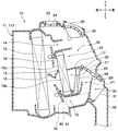
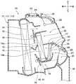
空調ユニット10は、図1、図2に示すように、外殻を形成すると共に、送風ユニットからの送風空気を車室内に向かって流す空気通路を形成する空調ケース11を有する。空調ケース11は、ある程度の弾性を有し、強度的にも優れた樹脂(例えば、ポリプロピレン)にて成形されている。なお、図1、図2において前後、左右、上下を示す矢印は、空調ユニット10を車両に搭載した状態での車両前後方向、車両左右方向、車両上下方向を示している。このことは、図1、図2以外の図面についても同様である。
本実施形態の空調ケース11は、車両左右方向の両側壁を構成する一対のケース部材111、112、および一対のケース部材111、112の間に介在される中間ケース部材113にて形成されている。すなわち、本実施形態の空調ケース11は、その中央部から所定間隔離れた位置に上下方向に延びる2つの分割面を有している。空調ケース11は、2つの分割面で一対のケース部材111、112および中間ケース部材113に分割することができる。なお、一対の中間ケース部材113における一対のケース部材111、112に当接する部位は、各ケース部材111、112の分割面に適合する形状となっている。
一対のケース部材111、112および中間ケース部材113は、その内部に空調ユニット10を構成する各種構成機器を収容した状態で、金属バネ、クリップ、ネジ等の図示しない締結部材によって結合されている。
本実施形態の中間ケース部材113は、車格の相違や空調ケース11に内蔵する各種構成機器の体格の相違に応じて一対のケース部材111、112の間隔幅を調整するための部材である。つまり、空調ケース11は、一対のケース部材111、112の分割面に左右幅の異なる中間ケース部材113を選択的に介在させることで、車格の相違、内蔵する各種構成機器の体格等の相違に応じて、空調ケース11の体格を調整可能となっている。
中間ケース部材113としては、例えば、図1に示す左右幅を基準幅L1とする基準中間ケース部材113A、図2に示す左右幅を基準幅L1よりも長い伸縮幅L2とする伸縮中間ケース部材113Bが選択可能となっている。
本実施形態では、中間ケース部材113として図1に示す基準中間ケース部材113Aを用いて空調ケース11を形成した例について説明する。なお、中間ケース部材113として伸縮中間ケース部材113Bを適用した形成した空調ケースについては、本実施形態の参考例とする。
以下、説明の便宜のため、図1に示す基準中間ケース部材113Aを用いた空調ケース11を基準ケース11Aと称し、図2に示す伸縮中間ケース部材113Bを用いた空調ケース11を伸縮ケース11Bと称することがある。
基準ケース11Aおよび伸縮ケース11Bは、一対のケース部材111、112の間に介在させる中間ケース部材113の車両左右方向の幅寸法や形状が異なるだけで、一対のケース部材111、112の形状等については同等となっている。すなわち、一対のケース部材111、112は、基準ケース11Aおよび伸縮ケース11Bで共用可能となっている。
続いて、空調ユニット10における空調ケース11の内部構造等について図3~図5を用いて説明する。図3は、中間ケース部材113側の内部構造を示し、図4は、一対のケース部材111、112側の内部構造を示している。
空調ケース11のうち最も車両前方側の部位の側面には、図示しない空気入口が形成されている。この空気入口には、前述の送風機ユニットのブロワケースからの送風空気が流入する。
図3~図5に示すように、空調ケース11内には、空気入口直後の部位に蒸発器12が配置されている。この蒸発器12は、図示しない蒸気圧縮式の冷凍サイクルを構成する機器の1つである。蒸発器12は、冷凍サイクル内の低圧冷媒を蒸発させて吸熱作用を発揮させることにより、送風空気を冷却する冷却部材である。
蒸発器12の空気流れ下流側(例えば、車両後方側)には、ヒータコア13が配置されている。ヒータコア13は、蒸発器12を通過した冷風を加熱する加熱部材である。ヒータコア13は、その内部に図示しないエンジン冷却水回路を循環する高温の冷却水が流れ、当該冷却水を熱源として空気を加熱する。
ヒータコア13は冷却水が通過するチューブ、当該チューブに接合されたフィンで構成される熱交換用のコア部を有している。ヒータコア13のコア部の空気流路は、コア部の前面側に位置する前側仕切壁16、およびコア部の後面側に位置する後側仕切壁17により、上方側流路13aと下方側流路13bとに仕切られている。各仕切壁16、17は空調ケース11内部で、車両幅方向、すなわち図3、図4の紙面垂直方向全域にわたって延びるように形成されている。
ヒータコア13の上端側には、蒸発器12を通過した冷風を、ヒータコア13を迂回して流す第1冷風バイパス通路14が形成されている。ヒータコア13の下端側には、蒸発器12を通過した冷風を、ヒータコア13を迂回して流す第2冷風バイパス通路15が形成されている。
また、ヒータコア13と蒸発器12との間には、温度調整手段として機能する第1、第2エアミックスドア18、19が配置されている。第1エアミックスドア18は、ヒータコア13の上方側流路13aで加熱された温風と、第1冷風バイパス通路14を通過した冷風との風量割合を調整する。ヒータコア13の上方側流路13aを通過した温風と第1冷風バイパス通路14を通過した冷風は、所望温度の空気となるように第1空気混合部20で混合される。
第2エアミックスドア19は、ヒータコア13の下方側流路13bで加熱された温風と、第2冷風バイパス通路15を通過した冷風との風量割合を調整する。ヒータコア13の下方側流路13bを通過した温風と第2冷風バイパス通路15を通過した冷風は、所望温度の空気となるように第2空気混合部21で混合される。
本実施形態の各エアミックスドア18、19は、蒸発器12の前面に沿ってスライド移動するスライドドアで構成されている。各エアミックスドア18、19は、図示しないアクチュエータに連結され、当該アクチュエータによりスライド位置が調整可能となっている。
本実施形態の車両用空調装置は、各エアミックスドア18、19それぞれのドア開度を独立して調整することで、空調ケース11内の空気を上下で異なる温度に調整可能となっている。
空調ケース11におけるヒータコア13の空気流れ下流側(例えば、車両後方側)には、上方側流路13aを通過した温風が流れる第1温風通路22が形成されている。第1温風通路22の下流側の上方側には、第1冷風バイパス通路14の下流側と合流しており、冷風と温風の混合を行う第1空気混合部20を形成している。
空調ケース11の上面部には、第1空気混合部20に隣接する部位にデフロスタ開口部23が開口している。デフロスタ開口部23は、第1空気混合部20で温度調整された空気が流入する。デフロスタ開口部23には、図示しないデフロスタダクトを介してデフロスタ吹出口に接続されている。デフロスタ開口部23を通過した空気は、デフロスタ吹出口から車両前面窓ガラスの内面に向けて吹き出される。
デフロスタ開口部23は、デフロスタドア24により切替開閉される。デフロスタドア24は、空調ケース11の上面部に近接して設けられている。デフロスタドア24は、車両左右方向に配置された回転軸により回動する片持ちドアで構成されている。デフロスタドア24は、図示しないアクチュエータに連結されて、当該アクチュエータにより回転操作される。
また、空調ケース11の上面部には、デフロスタ開口部23よりも車両後方側の乗員寄りの部位に前席フェイス開口部25が開口している。前席フェイス開口部25は、第1空気混合部20で温度調整された空気が流入する。前席フェイス開口部25は、図示しないフェイスダクトを介して、計器盤上方側に配置されているフェイス吹出口に接続されている。前席フェイス開口部25を通過した空気は、フェイス吹出口から車室内前席の乗員の上半身に向けて吹き出される。
前席フェイス開口部25は、フェイスドア26により切替開閉される。フェイスドア26は、空調ケース11の上面部に近接して設けられている。フェイスドア26は、車両左右方向に配置された回転軸により回動するロータリドアで構成されている。フェイスドア26は、図示しないアクチュエータに連結され、当該アクチュエータにより回転操作される。
後側仕切壁17の下方側には、ヒータコア13の下方側流路13bを通過した温風が流れる第2温風通路27が形成されている。第2温風通路27の空気流れ下流側(例えば、車両後方側)は、第2冷風バイパス通路15の下流側と合流し、冷風と温風の混合を行う第2空気混合部21を形成している。
本実施形態の第2温風通路27には、加熱部材を構成する電気ヒータ28が配置されている。電気ヒータ28としては、例えば、PTC素子に通電することで発熱するPTCヒータを採用することができる。
空調ケース11の車両後方部には、第2空気混合部21に近接する部位にフット開口部29が開口している。フット開口部29には、第2空気混合部21で温度調整された空気が流入する。
フット開口部29の空気流れ下流側には、前席用開口部を構成する前席フット開口部30、および後席用開口部31が開口している。すなわち、本実施形態では、前席フット開口部30および後席用開口部31が、フット開口部29という共通の開口部の下流側に形成されている。
前席フット開口部30には、フット開口部29を介して第2空気混合部21で温度調整された空気が流入する。本実施形態の前席フット開口部30は、図1、図2に示すように、空調ケース11の一対のケース部材111、112に開口している。前席フット開口部30を通過した空気は、図示しない左右両側の前席用フット吹出口を経て前席の乗員の下半身へ吹き出される。
後席用開口部31には、フット開口部29を介して第2空気混合部21で温度調整された空気が流入する。本実施形態の後席用開口部31は、図1、図2に示すように、空調ケース11の中間ケース部材113に開口している。後席用開口部31は、接続ダクト32を経て、図示しない後席用のフェイス吹出口、または、図示しない後席用のフット吹出口に接続されている。後席用開口部31を通過した空気は、後席用のフェイス吹出口、または、後席用フット吹出口から後席乗員に向けて吹き出される。
図3、図4に示す接続ダクト32は、計器盤付近から車室内前席の下部付近まで延びるダクトであり、後席用開口部31から流出する空気の通風抵抗となる。このため、後席用開口部31の下流側は、前席フット開口部30の下流側に比べて通風抵抗が大きくなっている。
後側仕切壁17は、空調ケース11の車両後方側壁面付近まで延びており、第1、第2空気混合部20、21を仕切る仕切壁として機能する。後側仕切壁17には、第1、第2空気混合部20、21を連通するフェイスフット連通口33が形成されている。
空調ケース11の車両後方部には、フット開口部29およびフェイスフット連通口33を選択的に開閉するフットドア34が配置されている。フットドア34は、図示しないアクチュエータに連結されて、このアクチュエータにより回転操作されるようになっている。
ここで、本実施形態の中間ケース部材113には、図6に示すように、左右方向の中央部に上下方向に延びる左右仕切壁35が設けられている。空調ケース11内部の空気通路14、15、22、27は、左右仕切壁35により、左側通路36を構成する各通路14a、15a、22a、27a、および右側通路37を構成する各通路14b、15b、22b、27bに仕切られている。本実施形態の各エアミックスドア18、19は、左側通路36および右側通路37を流れる空気の温度を個別に調整可能に構成されている。
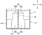
図7は、第2冷風バイパス通路15側からフット開口部29を見た際の空調ケース11の模式的な内部構造を示している。図7に示すように、本実施形態のフット開口部29は、左右仕切壁35により、左右の開口部29a、29bに分割されている。そして、フット開口部29は、一対のケース部材111、112、中間ケース部材113に跨って形成されている。本実施形態のフット開口部29の各開口部29a、29bは、中間ケース部材113に形成された左右に延びる開口と、一対のケース部材111、112に形成された上下に延びる開口との組み合わせにより形成されている。
ここで、図8は、紙面上方に基準ケース11Aにおける第2冷風バイパス通路15側からフット開口部29を見た図を示し、紙面下方に伸縮ケース11Bにおける第2冷風バイパス通路15側からフット開口部29を見た図を示している。
図8に示すように、基準ケース11Aにおける中間ケース部材113の左右の幅L1は、伸縮ケース11Bにおける中間ケース部材113の左右の幅L2よりも短い。このため、基準ケース11Aは、左右の幅の寸法差ΔL(=L2-L1)によって、伸縮ケース11Bに比べて、第2冷風バイパス通路15が狭くなる。この際、第2冷風バイパス通路15の通路幅は、前席フット開口部30が形成された一対のケース部材111、112側で変化せず、後席用開口部31が形成された中間ケース部材113側が狭くなる。
この結果、基準ケース11Aでは、第2冷風バイパス通路15を通過する冷風は、後席用開口部31側に流れ難く、前席フット開口部30側に偏って流れてしまう。このような冷風の偏りは、前席フット開口部30および後席用開口部31に流入する空気の温度が乖離する要因となることから好ましくない。
そこで、本実施形態では、図9に示すように、中間ケース部材113における第2冷風バイパス通路15を構成する空間に、第2冷風バイパス通路15を流れる冷風を後席用開口部31側に導くガイド部材40を配置している。
本実施形態のガイド部材40は、中間ケース部材113と一対のケース部材111、112との連結部に沿って後席用開口部31側へ延びる整流板41、および整流板41を支持する枠体42で構成されている。
整流板41は、図3、図4に示すように、第2エアミックスドア19の下流であって、第2空気混合部21の上流側に形成される第2冷風バイパス通路15に配置されている。本実施形態の整流板41は、中間ケース部材113の分割面である左右の端部に設けられている。
整流板41は、第2冷風バイパス通路15の上壁面から下壁面まで延びる板部材で構成されている。このため、本実施形態の第2冷風バイパス通路15は、整流板41により左右方向に分割されている。
枠体42は、第2冷風バイパス通路15における整流板41よりも内側に配置されている。枠体42は、整流板41を支持可能なように、整流板41に連結されている。枠体42は、第2冷風バイパス通路15の通風抵抗を抑えるために、第2冷風バイパス通路15の上壁面および下壁面に沿って延びる形状とすることが好ましい。
また、本実施形態のガイド部材40は、中間ケース部材113におけるヒータコア13を支持する支持壁に係合する係合部43を有する。本実施形態の係合部43は、整流板41に設けられている。ガイド部材40は、当該係合部43により中間ケース部材113に脱着可能に取付けられている。
続いて、本実施形態の車両用空調装置の電気制御部について説明する。図示しないが空調制御装置は、CPU、ROMやRAM等の各種メモリを含むマイクロコンピュータとその周辺回路により構成されている。空調制御装置は、メモリに記憶された制御プログラムに基づいて、各種演算処理を行い、出力側に接続された各種機器の作動を制御する。
空調制御装置の入力側には、車室内気温を検出する内気センサ、車室外気温を検出する外気センサ、車室内への日射量を検出する日射センサ等のセンサ群、車室内の計器盤付近に配置される操作パネルが接続されている。
次に、上記構成に係る本実施形態の車両用空調装置の作動について説明する。車両用空調装置は、車両作動状態において、操作パネルから作動信号が入力されると、空調制御装置が制御プログラムを実行する。これにより、空調制御装置は、センサ群の検出信号、および操作パネルの操作信号を読み込み、これら信号に基づいて、各種機器の作動を制御する。
具体的には、空調制御装置は、センサ群の検出信号および操作パネルの操作信号に基づいて、車室内へ吹き出す空気の目標吹出温度を算出する。そして、空調制御装置は、目標吹出温度に基づいて、送風機ユニットの電動モータ、各ドア18、19、24、26、34のアクチュエータ等の制御状態を決定し、決定した制御状態が得られるように、各種アクチュエータに制御信号を出力する。
空調制御装置は、目標吹出温度が極低温、または極高温となる場合に、送風機ユニットの送風量が最大となるように電動モータを制御する。そして、目標吹出温度が、中間温度に近づくに伴って送風機ユニットの送風量が減少するように電動モータを制御する。空調制御装置は、外気温が予め定めた基準外気温以下となっているときに電気ヒータ28に通電する。
また、空調制御装置は、目標吹出温度、センサ群の検出値に基づいて、各エアミックスドア18、19のドア開度を決定し、決定されたドア開度となるようにアクチュエータを制御する。本実施形態では、各エアミックスドア18、19により各温風通路22、27が全閉されている状態が、最大冷房状態(すなわち、MaxCool)であり、この際のドア開度は0%となっている。また、本実施形態では、各エアミックスドア18、19により冷風バイパス通路14、15が全閉されている状態が、最大暖房状態(すなわち、MaxHot)であり、この際のドア開度は100%となっている。
空調制御装置は、目標吹出温度が低温域から高温域へと上昇するに伴って、吹出モードがフェイスモード→バイレベルモード→フットモードへ移行されるように、各開口部23、25、29を開閉する各ドア24、26、34のアクチュエータを制御する。
ここで、フェイスモードは、フェイスドア26により前席フェイス開口部25を開放し、車室内の乗員の上半身に向けて空気を吹き出す吹出モードである。また、バイレベルモードは、フェイスドア26およびフットドア34により、前席フェイス開口部25、およびフット開口部29の双方を開放し、車室内の乗員の上半身および足元に向けて空気を吹き出す吹出モードである。また、フットモードは、フットドア34により、フット開口部29を開放し、車室内の乗員の足元等に向けて空気を吹き出す吹出モードである。
本実施形態の車両用空調装置は、乗員が操作パネルのデフロスタスイッチをオンすることにより、デフロスタモードへ切替可能となっている。デフロスタモードは、デフロスタドア24によりデフロスタ開口部23を開放し、車両窓ガラスの内面に向けて空気を吹き出す吹出モードである。
また、本実施形態の車両空調装置は、乗員が操作パネルの後席スイッチをオンすることにより、後席空調モードへ切替可能となっている。後席空調モードは、フットドア34によりフット開口部29を開放し、後席用開口部31を介して後席に向けて空気を吹き出す吹出モードである。
以上の如く、本実施形態の車両用空調装置では、各種センサ群の検出信号等に応じて、種々の吹出モードを切り替えることによって、適切な車室内の空調を実現することができる。
特に、本実施形態では、中間ケース部材113における第2冷風バイパス通路15を構成する空間に、第2冷風バイパス通路15を流れる冷風を後席用開口部31側に導くガイド部材40を配置している。これによれば、中間ケース部材113に後席用開口部31を設けたとしても、蒸発器12を通過した空気を後席用開口部31に導くことができ、車両用前席側への吹き出す空気の吹出温度と、車室内後席側へ吹き出す空気の吹出温度との乖離を抑えることができる。
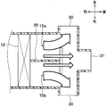
この点について図10、図11を用いて説明する。図10は、第2冷風バイパス通路15の空気の流れを示す模式的な断面図であり、第2冷風バイパス通路15にガイド部材40の整流板41を配置している本実施形態の構成を示している。図11は、第2冷風バイパス通路15の空気の流れを示す模式的な断面図であり、第2冷風バイパス通路15にガイド部材40の整流板41を配置していない比較例の構成を示している。なお、図10は、図5のX-X断面図に相当する。
図10に示すように、本実施形態の構成では、第2冷風バイパス通路15を通過する空気が、ガイド部材40の整流板41の壁面に沿って、後席用開口部31側へ流れる。このため、本実施形態の構成では、後席用開口部31側へ空気を導く中間ケース部材113の空気通路が狭い場合であっても、第2冷風バイパス通路15を通過する空気を前席フット開口部30および後席用開口部31の双方に適切に流すことができる。
一方、比較例の構成では、図11に示すように、後席用開口部31側へ空気を流す中間ケース部材113の空気通路が狭いことによって、第2冷風バイパス通路15を通過する空気が、前席フット開口部30側へ偏って流れる。
これにより、比較例では、図12に示すように、前席フット開口部30を介して車室内前席へ吹き出す空気の吹出温度が、後席用開口部31を介して車室内後席側へ吹き出す空気の吹出温度よりも低下する。
その理由としては、冷風が温風に比べて空気密度が高く慣性力が大きいことにあると推察される。すなわち、第2冷風バイパス通路15において、前席フット開口部30側に冷風の流れが偏ると、第2空気混合部21を介して前席フット開口部30側へ流れる温風が、慣性力の大きい冷風によって後席用開口部31側に押し出される。この結果、前席フット開口部30に流入する空気の温度が、後席用開口部31に流入する空気の温度よりも低下してしまうと考えられる。
これに対して、本実施形態の構成では、第2冷風バイパス通路15を通過する空気を前席フット開口部30および後席用開口部31の双方に適切に流すことができる。このため、前席フット開口部30に流入する空気の温度を、後席用開口部31に流入する空気の温度と同等の温度にすることができる。
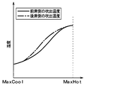
この結果、本実施形態の構成では、図13に示すように、車室内前席側へ吹き出す空気の吹出温度と車室内後席側へ吹き出す空気の吹出温度との乖離を抑制することができる。なお、図12および図13における横軸は、第2エアミックスドア19のドア開度を示しており、左側がMaxCoolの状態、右側がMaxHotの状態を示している。
また、本実施形態では、ガイド部材40として、後席用開口部31側に向かって延びる整流板41を有している。これによると、第2冷風バイパス通路15を流れる冷風を整流板41の板面に沿って後席用開口部31側へ導くことができる。なお、ガイド部材40の整流板41は、一枚だけでなく複数枚有する構成としてもよい。
さらに、本実施形態のガイド部材40は、第2冷風バイパス通路15の任意の位置に配置することができるように、中間ケース部材113に対して脱着可能に構成されている。これによれば、基準中間ケース部材113A、および伸縮中間ケース部材113Bといった各種中間ケース部材113で、ガイド部材40を共用させることが可能となる。
また、本実施形態の車両用空調装置は、後席用開口部31の下流側が、前席フット開口部30の下流側よりも通風抵抗が大きくなっている。このような車両用空調装置では、後席用開口部31の下流側の通風抵抗によって、後席用開口部31へ空気が流れ難く、第2冷風バイパス通路15を通過する空気が、前席フット開口部30側へ偏って流れ易い。
従って、後席用開口部31の下流側が、前席フット開口部30の下流側よりも通風抵抗が大きくなる車両用空調装置に対して、中間ケース部材113の第2冷風バイパス通路15に後席用開口部31側に導くガイド部材40を配置する構成は好適である。
ここで、車室内前席側の吹出温度と、車室内後席側の吹出温度とを同等とするために、第2エアミックスドア19の下流側から前席フット開口部30に至る空気通路と、後席用開口部31に至る空気通路とを仕切壁によって仕切る構成が考えられる。
しかし、このような通路構成とすると、第2エアミックスドア19の下流側の空気通路が狭くなり、通風抵抗の増大が懸念される。このため、本実施形態の如く、第2エアミックスドア19の下流側であって、第2空気混合部21の上流側に形成される第2冷風バイパス通路15に限定して、ガイド部材40を配置することが好ましい。
(第2実施形態)
次に、第2実施形態について説明する。本実施形態では、ガイド部材40の枠体42を廃している点が第1実施形態と相違している。本実施形態では、第1実施形態と同様または均等な部分についての説明を省略、または簡略化して説明する。
次に、第2実施形態について説明する。本実施形態では、ガイド部材40の枠体42を廃している点が第1実施形態と相違している。本実施形態では、第1実施形態と同様または均等な部分についての説明を省略、または簡略化して説明する。
図14は、第2実施形態のガイド部材40を示す斜視図である。図14に示すように、本実施形態のガイド部材40は、第1実施形態の枠体42を廃し、整流板41、および係合部43で構成されている。本実施形態の整流板41は、第2冷風バイパス通路15の上壁面、および下壁面とで支持する構成となっている。
これによれば、整流板41を支持する枠体42を省略したことで、簡素なガイド部材40により、車両用前席側への吹き出す空気の吹出温度と、車室内後席側へ吹き出す空気の吹出温度との乖離を抑えることができる。
また、枠体42の省略に伴い、ガイド部材40における第2冷風バイパス通路15における通風抵抗となる要素を少なくすることができる。
(第3実施形態)
次に、第3実施形態について説明する。本実施形態では、ガイド部材40に対して敢えて通風抵抗となる要素を付加している点が第1、第2実施形態と相違している。本実施形態では、第1、第2実施形態と同様または均等な部分についての説明を省略、または簡略化して説明する。
次に、第3実施形態について説明する。本実施形態では、ガイド部材40に対して敢えて通風抵抗となる要素を付加している点が第1、第2実施形態と相違している。本実施形態では、第1、第2実施形態と同様または均等な部分についての説明を省略、または簡略化して説明する。
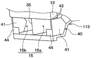
図15は、第3実施形態のガイド部材40を示す斜視図である。図15に示すように、本実施形態のガイド部材40は、整流板41の空気流れ上流側の端部に、バッフル44を設ける構成としている。バッフル44は、整流板41の内側を流れる空気流れに対して交差する方向に延びる板状部材で構成されている。本実施形態のバッフル44は、整流板41と一体に形成されている。
本実施形態では、ガイド部材40に対して、第2冷風バイパス通路15における通風抵抗となるバッフル44を敢えて付加している。これによれば、バッフル44により第2冷風バイパス通路15における冷風の流れが乱れることで、第2冷風バイパス通路15の下流側の第2空気混合部21における温風との混合促進を図ることができる。
(第4実施形態)
次に、第4実施形態について説明する。本実施形態では、中間ケース部材113の分割面の内側にガイド部材40の整流板41を配置している点が第1~第3実施形態と相違している。本実施形態では、第1~第3実施形態と同様または均等な部分についての説明を省略、または簡略化して説明する。
次に、第4実施形態について説明する。本実施形態では、中間ケース部材113の分割面の内側にガイド部材40の整流板41を配置している点が第1~第3実施形態と相違している。本実施形態では、第1~第3実施形態と同様または均等な部分についての説明を省略、または簡略化して説明する。
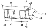
図16は、第4実施形態のガイド部材40を示す斜視図である。図16に示すように、本実施形態のガイド部材40は、枠体42が中間ケース部材113に分割面側に配置されている。本実施形態では、中間ケース部材113におけるヒータコア13を支持する支持壁に係合する係合部43が、枠体42に設けられている。
そして、整流板41は、第2冷風バイパス通路15における枠体42よりも内側に配置されている。すなわち、本実施形態の整流板41は、中間ケース部材113における分割面よりも内側に配置されている。
本実施形態のガイド部材40は、枠体42を中間ケース部材113の分割面側に配置すると共に、枠体42に係合部45に設ける構成としているので、整流板41を中間ケース部材113における分割面よりも内側に配置することができる。これによれば、中間ケース部材113における後席用開口部31の形成位置に合わせて、整流板41を配置することが可能となり、より適切に冷風バイパス通路15を流れる空気を後席用開口部31側に向けて導くことができる。
(他の実施形態)
以上、本開示の実施形態について説明したが、本開示は上述の実施形態に限定されるものではなく、適宜変更が可能である。例えば、以下のように種々変形可能である。
以上、本開示の実施形態について説明したが、本開示は上述の実施形態に限定されるものではなく、適宜変更が可能である。例えば、以下のように種々変形可能である。
上述の各実施形態では、前側仕切壁16および後側仕切壁17により空調ケース11内部の空気通路が上下に分割された車両用空調装置に本開示を適用する例を説明したが、本開示の適用はこれに限定されない。本開示は、空調ケース11内部の空気通路が上下に分割されていない車両用空調装置に対して適用してもよい。
上述の各実施形態では、左右仕切壁35により空調ケース11内部の空気通路が左右に分割された車両用空調装置に本開示を適用する例を説明したが、本開示の適用はこれに限定されない。本開示は、空調ケース11内部の空気通路が左右に分割されていない車両用空調装置に対して適用してもよい。
上述の各実施形態では、各エアミックスドア18、19それぞれのドア開度を独立して調整可能な車両用空調装置に本開示を適用する例を説明したが、本開示の適用はこれに限定されない。例えば、単一または3枚以上のエアミックスドアを備える車両用空調装置に対して本開示を適用してもよい。また、各エアミックスドア18、19は、スライドドアだけでなく、片持ちドア等で構成してもよい。
上述の各実施形態では、前席フット開口部30が一対のケース部材111、112に設けた車両用空調装置に本開示を適用する例について説明したが、これに限定されない。例えば、前席フェイス開口部25が一対のケース部材111、112に設けられている車両用空調装置に対して、本開示を適用してもよい。この場合、前席フェイス開口部25の吹出温度と後席用開口部31の吹出温度の乖離が抑制されるように中間ケース部材113にガイド部材40を配置すればよい。
上述の各実施形態の如く、ガイド部材40を中間ケース部材113に対して脱着可能とする構成が望ましいが、これに限定されない。例えば、ガイド部材40は、中間ケース部材113と一体に成形されていてもよい。
上述の各実施形態では、ガイド部材40として後席用開口部31側に向かって延びる整流板41を有する構成としているが、これに限定されない。例えば、ガイド部材40として、後席用開口部31側に対して冷風の向きを転向させるルーバー状の風向板を有する構成としてもよい。
上述の各実施形態では、整流板41を、第2冷風バイパス通路15の上壁面から下壁面まで延びる板部材で構成する例について説明したが、これに限定されない。例えば、整流板41として、第2冷風バイパス通路15の上壁面から下方に延びる板状部材や、下壁面から上方に延びる板部材で構成してもよい。この際、整流板41には、第2冷風バイパス通路15の一部で左右に形成される空気通路を連通させる連通部が形成されていてもよい。
上述の各実施形態において、実施形態を構成する要素は、特に必須であると明示した場合および原理的に明らかに必須であると考えられる場合等を除き、必ずしも必須のものではないことは言うまでもない。
上述の各実施形態において、実施形態の構成要素の個数、数値、量、範囲等の数値が言及されている場合、特に必須であると明示した場合および原理的に明らかに特定の数に限定される場合等を除き、その特定の数に限定されない。
上述の各実施形態において、構成要素等の形状、位置関係等に言及するときは、特に明示した場合および原理的に特定の形状、位置関係等に限定される場合等を除き、その形状、位置関係等に限定されない。
Claims (6)
- 車両用空調装置であって、
一対のケース部材(111、112)の間に中間ケース部材(113)を介在させることによって車室内へ吹き出す空気の空気通路を形成する空調ケース(11、11A、11B)と、
前記空調ケース内に配置され、前記空気通路を流れる空気を冷却する冷却部材(12)と、
前記空調ケース内に配置され、前記冷却部材を通過した空気を加熱する加熱部材(13、28)と、を備え、
前記空調ケースには、前記冷却部材を通過した空気を前記加熱部材を迂回して流す冷風バイパス通路(15)が設けられると共に、前記冷風バイパス通路を通過した冷風および前記加熱部材を通過した温風を流出させる複数の開口部(23、25、30、31)が形成されており、
前記複数の開口部は、前記一対のケース部材に形成されて前記車室内の前席側へ空気を流出させる前席用開口部(30)、および前記中間ケース部材に形成されて前記車室内の後席側へ空気を流出させる後席用開口部(31)を含んで構成されており、
前記中間ケース部材には、前記冷風バイパス通路を構成する空間に、前記冷却部材を通過した空気を前記後席用開口部側に導くガイド部材(40)が配置されている車両用空調装置。 - 前記ガイド部材は、前記後席用開口部側に向かって延びる整流板(41)を有している請求項1に記載の車両用空調装置。
- 前記ガイド部材は、前記中間ケース部材に対して脱着可能に構成されている請求項1または2に記載の車両用空調装置。
- 前記後席用開口部の下流側は、前記前席用開口部の下流側に比べて通風抵抗が大きくなっている請求項1ないし3のいずれか1つに記載の車両用空調装置。
- 前記前席用開口部は、前記車室内前席側の乗員の足元に向かって吹き出す空気を前記空調ケースから流出させる前席フット開口部(30)であり、
前記後席用開口部は、前記車室内後席側の乗員の足元または上半身に向かって吹き出す空気を前記空調ケースから流出させる開口部である請求項1ないし4のいずれか1つに記載の車両用空調装置。 - 前記空調ケースには、前記冷風バイパス通路の下流側であって、前記前席用開口部(30)、および前記後席用開口部(31)の上流側に、前記冷却部材を通過した空気と前記加熱部材を通過した空気とを混合する空気混合部(21)が形成されており、
前記ガイド部材は、前記空気混合部(21)の上流側に配置されている請求項1ないし5のいずれか1つに記載の車両用空調装置。
Applications Claiming Priority (2)
| Application Number | Priority Date | Filing Date | Title |
|---|---|---|---|
| JP2015-019318 | 2015-02-03 | ||
| JP2015019318A JP2018047711A (ja) | 2015-02-03 | 2015-02-03 | 車両用空調装置 |
Publications (1)
| Publication Number | Publication Date |
|---|---|
| WO2016125731A1 true WO2016125731A1 (ja) | 2016-08-11 |
Family
ID=56564076
Family Applications (1)
| Application Number | Title | Priority Date | Filing Date |
|---|---|---|---|
| PCT/JP2016/052892 Ceased WO2016125731A1 (ja) | 2015-02-03 | 2016-02-01 | 車両用空調装置 |
Country Status (2)
| Country | Link |
|---|---|
| JP (1) | JP2018047711A (ja) |
| WO (1) | WO2016125731A1 (ja) |
Cited By (13)
| Publication number | Priority date | Publication date | Assignee | Title |
|---|---|---|---|---|
| KR20180068760A (ko) * | 2016-12-14 | 2018-06-22 | 현대자동차주식회사 | 자동차용 트리플 존 공기조화장치 |
| CN108215706A (zh) * | 2016-12-14 | 2018-06-29 | 现代自动车株式会社 | 用于汽车的暖通空调装置 |
| WO2018139033A1 (ja) * | 2017-01-30 | 2018-08-02 | 株式会社デンソー | 車両用空調装置 |
| JP2018122847A (ja) * | 2017-01-30 | 2018-08-09 | 株式会社デンソー | 車両用空調装置 |
| WO2019021707A1 (ja) * | 2017-07-25 | 2019-01-31 | 株式会社デンソー | 車両用空調ユニット |
| JP2019135137A (ja) * | 2017-07-25 | 2019-08-15 | 株式会社デンソー | 車両用空調ユニット |
| JP2019156115A (ja) * | 2018-03-12 | 2019-09-19 | 株式会社ケーヒン | 車両用空調装置 |
| JP2019172027A (ja) * | 2018-03-28 | 2019-10-10 | 株式会社ケーヒン | 車両用空調装置 |
| JP2020142628A (ja) * | 2019-03-06 | 2020-09-10 | 株式会社ケーヒン | 車両用空調装置 |
| WO2021209409A1 (fr) * | 2020-04-15 | 2021-10-21 | Valeo Systemes Thermiques | Dispositif de chauffage, ventilation et/ou climatisation pour vehicule automobile |
| WO2021209408A1 (fr) * | 2020-04-15 | 2021-10-21 | Valeo Systemes Thermiques | Dispositif de chauffage, ventilation et/ou climatisation pour vehicule automobile |
| WO2024002113A1 (zh) * | 2022-06-30 | 2024-01-04 | 法雷奥汽车空调湖北有限公司 | 供暖、通风和/或空调装置及机动车辆 |
| WO2026041114A1 (zh) * | 2024-08-23 | 2026-02-26 | 法雷奥汽车空调湖北有限公司 | 空调模块和机动车辆 |
Families Citing this family (1)
| Publication number | Priority date | Publication date | Assignee | Title |
|---|---|---|---|---|
| JP6965824B2 (ja) * | 2018-05-10 | 2021-11-10 | 株式会社デンソー | 乗り物用空調装置 |
Citations (5)
| Publication number | Priority date | Publication date | Assignee | Title |
|---|---|---|---|---|
| JP2004114889A (ja) * | 2002-09-27 | 2004-04-15 | Denso Corp | 自動車用空調装置 |
| JP2004230995A (ja) * | 2003-01-29 | 2004-08-19 | Denso Corp | 車両用空調装置 |
| JP2004243932A (ja) * | 2003-02-14 | 2004-09-02 | Denso Corp | 車両用空調装置 |
| JP2008179175A (ja) * | 2007-01-23 | 2008-08-07 | Calsonic Kansei Corp | 車両用空気調和装置 |
| JP2011207279A (ja) * | 2010-03-29 | 2011-10-20 | Denso Corp | 空調ケース |
-
2015
- 2015-02-03 JP JP2015019318A patent/JP2018047711A/ja active Pending
-
2016
- 2016-02-01 WO PCT/JP2016/052892 patent/WO2016125731A1/ja not_active Ceased
Patent Citations (5)
| Publication number | Priority date | Publication date | Assignee | Title |
|---|---|---|---|---|
| JP2004114889A (ja) * | 2002-09-27 | 2004-04-15 | Denso Corp | 自動車用空調装置 |
| JP2004230995A (ja) * | 2003-01-29 | 2004-08-19 | Denso Corp | 車両用空調装置 |
| JP2004243932A (ja) * | 2003-02-14 | 2004-09-02 | Denso Corp | 車両用空調装置 |
| JP2008179175A (ja) * | 2007-01-23 | 2008-08-07 | Calsonic Kansei Corp | 車両用空気調和装置 |
| JP2011207279A (ja) * | 2010-03-29 | 2011-10-20 | Denso Corp | 空調ケース |
Cited By (21)
| Publication number | Priority date | Publication date | Assignee | Title |
|---|---|---|---|---|
| CN108215704A (zh) * | 2016-12-14 | 2018-06-29 | 现代自动车株式会社 | 用于汽车的三区hvac装置 |
| CN108215706A (zh) * | 2016-12-14 | 2018-06-29 | 现代自动车株式会社 | 用于汽车的暖通空调装置 |
| KR102474617B1 (ko) * | 2016-12-14 | 2022-12-06 | 현대자동차주식회사 | 자동차용 트리플 존 공기조화장치 |
| KR20180068760A (ko) * | 2016-12-14 | 2018-06-22 | 현대자동차주식회사 | 자동차용 트리플 존 공기조화장치 |
| WO2018139033A1 (ja) * | 2017-01-30 | 2018-08-02 | 株式会社デンソー | 車両用空調装置 |
| JP2018122847A (ja) * | 2017-01-30 | 2018-08-09 | 株式会社デンソー | 車両用空調装置 |
| WO2019021707A1 (ja) * | 2017-07-25 | 2019-01-31 | 株式会社デンソー | 車両用空調ユニット |
| JP2019135137A (ja) * | 2017-07-25 | 2019-08-15 | 株式会社デンソー | 車両用空調ユニット |
| JP2019156115A (ja) * | 2018-03-12 | 2019-09-19 | 株式会社ケーヒン | 車両用空調装置 |
| JP7075258B2 (ja) | 2018-03-28 | 2022-05-25 | マーレ インターナショナル ゲゼルシャフト ミット ベシュレンクテル ハフツング | 車両用空調装置 |
| JP2019172027A (ja) * | 2018-03-28 | 2019-10-10 | 株式会社ケーヒン | 車両用空調装置 |
| JP7089490B2 (ja) | 2019-03-06 | 2022-06-22 | マーレ インターナショナル ゲゼルシャフト ミット ベシュレンクテル ハフツング | 車両用空調装置 |
| JP2020142628A (ja) * | 2019-03-06 | 2020-09-10 | 株式会社ケーヒン | 車両用空調装置 |
| FR3109334A1 (fr) * | 2020-04-15 | 2021-10-22 | Valeo Systemes Thermiques | Dispositif de chauffage, ventilation et/ou climatisation pour véhicule automobile |
| FR3109333A1 (fr) * | 2020-04-15 | 2021-10-22 | Valeo Systemes Thermiques | Dispositif de chauffage, ventilation et/ou climatisation pour véhicule automobile |
| WO2021209408A1 (fr) * | 2020-04-15 | 2021-10-21 | Valeo Systemes Thermiques | Dispositif de chauffage, ventilation et/ou climatisation pour vehicule automobile |
| WO2021209409A1 (fr) * | 2020-04-15 | 2021-10-21 | Valeo Systemes Thermiques | Dispositif de chauffage, ventilation et/ou climatisation pour vehicule automobile |
| CN115380155A (zh) * | 2020-04-15 | 2022-11-22 | 法雷奥热系统公司 | 用于机动车辆的供暖、通风和/或空调装置 |
| US20230234420A1 (en) * | 2020-04-15 | 2023-07-27 | Valeo Systemes Thermiques | Heating, ventilation and/or air-conditioning device for a motor vehicle |
| WO2024002113A1 (zh) * | 2022-06-30 | 2024-01-04 | 法雷奥汽车空调湖北有限公司 | 供暖、通风和/或空调装置及机动车辆 |
| WO2026041114A1 (zh) * | 2024-08-23 | 2026-02-26 | 法雷奥汽车空调湖北有限公司 | 空调模块和机动车辆 |
Also Published As
| Publication number | Publication date |
|---|---|
| JP2018047711A (ja) | 2018-03-29 |
Similar Documents
| Publication | Publication Date | Title |
|---|---|---|
| WO2016125731A1 (ja) | 車両用空調装置 | |
| JP4424409B2 (ja) | 車両用空調装置 | |
| JP5556619B2 (ja) | 車両用空調装置 | |
| CN105307880B (zh) | 车辆用空调装置 | |
| JP5617779B2 (ja) | 車両用空調装置 | |
| US8460073B2 (en) | Air conditioner for vehicle | |
| US20090215379A1 (en) | Vehicular air-conditioning system | |
| US11554630B2 (en) | Vehicular air conditioner having heating heat exchanger disposed downstream of blower fan | |
| JP2003159929A (ja) | 車両用空調装置 | |
| JP6221890B2 (ja) | 車両用空調ユニット | |
| JP2017094753A (ja) | 車両用空調ユニット | |
| JP5125930B2 (ja) | 車両用空調装置 | |
| JP5353665B2 (ja) | 車両用空調装置 | |
| WO2016194674A1 (ja) | 車両用空調装置 | |
| JP2009035070A (ja) | 車両用空調装置 | |
| JP2010149566A (ja) | 車両用空調装置 | |
| JP2006001378A (ja) | 車両用空調装置 | |
| JP2005225445A (ja) | 自動車用空調装置 | |
| JP2011207279A (ja) | 空調ケース | |
| JP2011207278A (ja) | 空調ケース | |
| JP2008222024A (ja) | 車両用空調装置 | |
| JP4352859B2 (ja) | 車両用空調装置 | |
| JP5459237B2 (ja) | 車両用空調装置 | |
| JP2007131280A (ja) | 車両用空調装置 | |
| JP2014151827A (ja) | 車室内空調ユニット |
Legal Events
| Date | Code | Title | Description |
|---|---|---|---|
| 121 | Ep: the epo has been informed by wipo that ep was designated in this application |
Ref document number: 16746562 Country of ref document: EP Kind code of ref document: A1 |
|
| NENP | Non-entry into the national phase |
Ref country code: DE |
|
| NENP | Non-entry into the national phase |
Ref country code: JP |
|
| 122 | Ep: pct application non-entry in european phase |
Ref document number: 16746562 Country of ref document: EP Kind code of ref document: A1 |