WO2016125576A1 - タイヤ把持装置及びタイヤ検査装置 - Google Patents
タイヤ把持装置及びタイヤ検査装置 Download PDFInfo
- Publication number
- WO2016125576A1 WO2016125576A1 PCT/JP2016/051363 JP2016051363W WO2016125576A1 WO 2016125576 A1 WO2016125576 A1 WO 2016125576A1 JP 2016051363 W JP2016051363 W JP 2016051363W WO 2016125576 A1 WO2016125576 A1 WO 2016125576A1
- Authority
- WO
- WIPO (PCT)
- Prior art keywords
- tire
- contact member
- contact
- chuck
- gripping device
- Prior art date
Links
- 238000007689 inspection Methods 0.000 title claims description 129
- 238000000034 method Methods 0.000 title description 61
- 239000011324 bead Substances 0.000 claims abstract description 129
- 230000007246 mechanism Effects 0.000 claims abstract description 107
- 230000033001 locomotion Effects 0.000 claims abstract description 68
- 238000012545 processing Methods 0.000 claims description 18
- 230000005540 biological transmission Effects 0.000 claims description 15
- 230000006698 induction Effects 0.000 claims description 9
- 230000003068 static effect Effects 0.000 claims description 8
- 230000008569 process Effects 0.000 description 37
- 238000003384 imaging method Methods 0.000 description 24
- 238000003825 pressing Methods 0.000 description 18
- 230000000694 effects Effects 0.000 description 13
- 230000006870 function Effects 0.000 description 13
- 238000010586 diagram Methods 0.000 description 12
- 230000008602 contraction Effects 0.000 description 8
- 230000003028 elevating effect Effects 0.000 description 7
- 230000009467 reduction Effects 0.000 description 7
- 230000001965 increasing effect Effects 0.000 description 6
- 238000004519 manufacturing process Methods 0.000 description 6
- 230000001629 suppression Effects 0.000 description 6
- 230000006872 improvement Effects 0.000 description 4
- 210000000078 claw Anatomy 0.000 description 3
- 238000012790 confirmation Methods 0.000 description 3
- 230000002950 deficient Effects 0.000 description 3
- 230000001788 irregular Effects 0.000 description 3
- 239000000463 material Substances 0.000 description 3
- VYZAMTAEIAYCRO-UHFFFAOYSA-N Chromium Chemical compound [Cr] VYZAMTAEIAYCRO-UHFFFAOYSA-N 0.000 description 2
- 230000008859 change Effects 0.000 description 2
- 238000006243 chemical reaction Methods 0.000 description 2
- 238000004891 communication Methods 0.000 description 2
- 230000007423 decrease Effects 0.000 description 2
- 239000006185 dispersion Substances 0.000 description 2
- 230000002349 favourable effect Effects 0.000 description 2
- 239000012530 fluid Substances 0.000 description 2
- 238000007747 plating Methods 0.000 description 2
- 230000002040 relaxant effect Effects 0.000 description 2
- 238000003860 storage Methods 0.000 description 2
- 230000003746 surface roughness Effects 0.000 description 2
- 238000004381 surface treatment Methods 0.000 description 2
- 238000012360 testing method Methods 0.000 description 2
- 235000006693 Cassia laevigata Nutrition 0.000 description 1
- 241000735631 Senna pendula Species 0.000 description 1
- 229910000831 Steel Inorganic materials 0.000 description 1
- 230000005856 abnormality Effects 0.000 description 1
- 238000013459 approach Methods 0.000 description 1
- 230000006399 behavior Effects 0.000 description 1
- 230000008901 benefit Effects 0.000 description 1
- 239000011248 coating agent Substances 0.000 description 1
- 238000000576 coating method Methods 0.000 description 1
- 230000000052 comparative effect Effects 0.000 description 1
- 230000000295 complement effect Effects 0.000 description 1
- 239000012141 concentrate Substances 0.000 description 1
- 238000011109 contamination Methods 0.000 description 1
- 230000003247 decreasing effect Effects 0.000 description 1
- 238000001514 detection method Methods 0.000 description 1
- 238000002474 experimental method Methods 0.000 description 1
- 239000000835 fiber Substances 0.000 description 1
- 238000007667 floating Methods 0.000 description 1
- 238000005286 illumination Methods 0.000 description 1
- 230000010365 information processing Effects 0.000 description 1
- 238000005259 measurement Methods 0.000 description 1
- 239000002184 metal Substances 0.000 description 1
- 229910044991 metal oxide Inorganic materials 0.000 description 1
- 150000004706 metal oxides Chemical class 0.000 description 1
- 230000010355 oscillation Effects 0.000 description 1
- 239000003973 paint Substances 0.000 description 1
- 238000012805 post-processing Methods 0.000 description 1
- 238000003672 processing method Methods 0.000 description 1
- 238000003908 quality control method Methods 0.000 description 1
- 239000011347 resin Substances 0.000 description 1
- 229920005989 resin Polymers 0.000 description 1
- 230000004043 responsiveness Effects 0.000 description 1
- 239000004065 semiconductor Substances 0.000 description 1
- 229940124513 senna glycoside Drugs 0.000 description 1
- 238000000926 separation method Methods 0.000 description 1
- 230000006641 stabilisation Effects 0.000 description 1
- 238000011105 stabilization Methods 0.000 description 1
- 230000000087 stabilizing effect Effects 0.000 description 1
- 239000010959 steel Substances 0.000 description 1
- 238000012546 transfer Methods 0.000 description 1
- 230000009466 transformation Effects 0.000 description 1
- 230000007704 transition Effects 0.000 description 1
- 238000011144 upstream manufacturing Methods 0.000 description 1
- 238000004804 winding Methods 0.000 description 1
Images


Classifications
-
- B—PERFORMING OPERATIONS; TRANSPORTING
- B29—WORKING OF PLASTICS; WORKING OF SUBSTANCES IN A PLASTIC STATE IN GENERAL
- B29D—PRODUCING PARTICULAR ARTICLES FROM PLASTICS OR FROM SUBSTANCES IN A PLASTIC STATE
- B29D30/00—Producing pneumatic or solid tyres or parts thereof
- B29D30/0016—Handling tyres or parts thereof, e.g. supplying, storing, conveying
-
- G—PHYSICS
- G01—MEASURING; TESTING
- G01M—TESTING STATIC OR DYNAMIC BALANCE OF MACHINES OR STRUCTURES; TESTING OF STRUCTURES OR APPARATUS, NOT OTHERWISE PROVIDED FOR
- G01M17/00—Testing of vehicles
- G01M17/007—Wheeled or endless-tracked vehicles
- G01M17/02—Tyres
- G01M17/021—Tyre supporting devices, e.g. chucks
-
- G—PHYSICS
- G01—MEASURING; TESTING
- G01M—TESTING STATIC OR DYNAMIC BALANCE OF MACHINES OR STRUCTURES; TESTING OF STRUCTURES OR APPARATUS, NOT OTHERWISE PROVIDED FOR
- G01M17/00—Testing of vehicles
- G01M17/007—Wheeled or endless-tracked vehicles
- G01M17/02—Tyres
-
- B—PERFORMING OPERATIONS; TRANSPORTING
- B29—WORKING OF PLASTICS; WORKING OF SUBSTANCES IN A PLASTIC STATE IN GENERAL
- B29D—PRODUCING PARTICULAR ARTICLES FROM PLASTICS OR FROM SUBSTANCES IN A PLASTIC STATE
- B29D30/00—Producing pneumatic or solid tyres or parts thereof
- B29D30/06—Pneumatic tyres or parts thereof (e.g. produced by casting, moulding, compression moulding, injection moulding, centrifugal casting)
-
- B—PERFORMING OPERATIONS; TRANSPORTING
- B66—HOISTING; LIFTING; HAULING
- B66C—CRANES; LOAD-ENGAGING ELEMENTS OR DEVICES FOR CRANES, CAPSTANS, WINCHES, OR TACKLES
- B66C1/00—Load-engaging elements or devices attached to lifting or lowering gear of cranes or adapted for connection therewith for transmitting lifting forces to articles or groups of articles
- B66C1/10—Load-engaging elements or devices attached to lifting or lowering gear of cranes or adapted for connection therewith for transmitting lifting forces to articles or groups of articles by mechanical means
- B66C1/42—Gripping members engaging only the external or internal surfaces of the articles
- B66C1/422—Gripping members engaging only the external or internal surfaces of the articles actuated by lifting force
-
- B—PERFORMING OPERATIONS; TRANSPORTING
- B66—HOISTING; LIFTING; HAULING
- B66C—CRANES; LOAD-ENGAGING ELEMENTS OR DEVICES FOR CRANES, CAPSTANS, WINCHES, OR TACKLES
- B66C1/00—Load-engaging elements or devices attached to lifting or lowering gear of cranes or adapted for connection therewith for transmitting lifting forces to articles or groups of articles
- B66C1/10—Load-engaging elements or devices attached to lifting or lowering gear of cranes or adapted for connection therewith for transmitting lifting forces to articles or groups of articles by mechanical means
- B66C1/42—Gripping members engaging only the external or internal surfaces of the articles
- B66C1/425—Gripping members engaging only the external or internal surfaces of the articles motor actuated
- B66C1/427—Gripping members engaging only the external or internal surfaces of the articles motor actuated by hydraulic or pneumatic motors
-
- G—PHYSICS
- G01—MEASURING; TESTING
- G01M—TESTING STATIC OR DYNAMIC BALANCE OF MACHINES OR STRUCTURES; TESTING OF STRUCTURES OR APPARATUS, NOT OTHERWISE PROVIDED FOR
- G01M17/00—Testing of vehicles
- G01M17/007—Wheeled or endless-tracked vehicles
- G01M17/02—Tyres
- G01M17/027—Tyres using light, e.g. infrared, ultraviolet or holographic techniques
Definitions
- the present invention relates to a tire gripping device and a tire inspection device.
- tires may require posture change or transportation (movement) in the manufacturing process, inspection process, logistics process, sales process, and the like.
- posture change or transportation movement
- a gripping member grip claw
- tire gripping device tire gripping device
- a gripping member is inserted inside the bead portion of the tire, the gripping member is expanded (expanded) in the tire radial direction, and the bead portion is radially outward.
- devices that grip and lift by pressing Such an apparatus may be used in particular in combination with an inspection apparatus.
- the tire is gripped and lifted by a tire gripping device, and the tire is rotated around the central axis.
- a photographing device and various sensors are arranged around the tire, and the entire circumference of the rotating tire is confirmed or photographed. And based on each acquired information, the process for quality control (shape inspection, surface inspection, etc.) and production management (model number, confirmation of a rod, etc.) is performed (for example, patent document 1).
- the conventional tire gripping device ensures the tire gripping force by expanding the gripping member in the tire radial direction.
- the contact posture (contact state) between the gripping member and the bead portion is changed. It may become uneven in the circumferential direction of the bead portion.
- This non-uniform contact posture (contact state) may cause pressure concentration in the tire radial direction at the positions of some gripping members and distort the tire (bead portion).
- Such tire distortion may cause noise in tire shape inspection and surface inspection, and may cause a decrease in inspection accuracy.
- one of the problems of the present invention is to provide a tire gripping device that can suppress tire distortion when gripping a tire by inserting a gripping mechanism inside a bead portion of the tire.
- a chuck mechanism including a pair of chuck portions arranged in a circumferential direction in a plurality of contact members that are in a non-relative movement state with the contact surface in a second contact step following the contact step; And a drive mechanism including a first drive mechanism that moves the contact member in the radial direction of the tire and a second drive mechanism that moves the pair of chuck portions in the width direction of the tire.
- a tire gripping device capable of reducing or suppressing tire distortion when the gripping member is brought into contact with the open end portion of the tire bead.
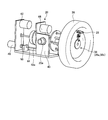
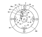
- FIG. 1 is a typical lineblock diagram showing an example of a tire inspection device provided with a tire gripping device concerning an embodiment.
- FIG. 2 is a schematic perspective view illustrating a state in which the chuck unit of the tire gripping device according to the embodiment grips a tire.
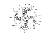
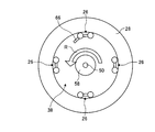
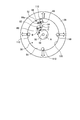
- FIG. 3 is a schematic plan view illustrating a state where the contact member of the chuck portion (chuck portion main body) in the tire gripping device according to the embodiment has a reduced diameter (released state, non-gripping state).
- FIG. 4 is a schematic plan view for explaining a state (grip state) in which the contact member of the chuck portion (chuck portion main body) in the tire gripping apparatus according to the embodiment is expanded in diameter.
- FIG. 1 is a typical lineblock diagram showing an example of a tire inspection device provided with a tire gripping device concerning an embodiment.
- FIG. 2 is a schematic perspective view illustrating a state in which the chuck unit of the tire gripping device according to the embodiment grips a tire.
- FIG. 3
- FIG. 5 is a schematic perspective view illustrating the detailed structure of the chuck portion main body (link mechanism) of the tire gripping device according to the embodiment.
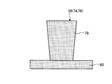
- FIG. 6 is a schematic plan view illustrating the shape of the abutting member of the front chuck portion of the tire gripping device according to the embodiment.
- FIG. 7 is a schematic plan view illustrating the shape of the contact member of the chuck portion on the rear side of the tire gripping device according to the embodiment.
- FIG. 8 is an explanatory diagram for explaining a state in which the clutch portion of the chuck unit of the tire gripping device according to the embodiment is in a disconnected state and the abutting member of the chuck portion main body is expanded and contracted.
- FIG. 9 is an explanatory diagram illustrating a state where the clutch unit of the chuck unit of the tire gripping device according to the embodiment is in a connected state and the entire chuck unit main body is rotated.
- Drawing 10 is an explanatory view explaining the state where the contact member in the tire gripping device concerning an embodiment has changed to the 1st contact stage.
- Drawing 11 is an explanatory view explaining the state where the contact member in the tire gripping device concerning an embodiment has changed to the 2nd contact stage.
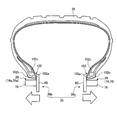
- Drawing 12 is an explanatory view explaining the state where the contact member in the tire gripping device concerning an embodiment has expanded in the tire width direction.
- FIG. 13 is an explanatory diagram illustrating a state in which the chuck body (chuck portion) of the tire gripping device according to the embodiment rotates around the central axis together with the tire.
- Drawing 14 is a typical side view explaining the hollow shape of the contact member in the tire gripping device concerning an embodiment.
- Drawing 15 is an explanatory view explaining the contact state of the contact member of the tire gripping device concerning an embodiment, and a bead part.
- FIG. 16 is a schematic side view illustrating an example in which a reflection suppressing process is performed on the contact member in the tire gripping device according to the embodiment.
- FIG. 17 is a schematic plan view illustrating an example in which rotation induction processing is performed on the contact member in the tire gripping device according to the embodiment.
- FIG. 18 is a flowchart for explaining the first half of the operation of the tire inspection apparatus according to the embodiment.
- FIG. 19 is a flowchart for explaining the latter half of the operation of the tire inspection apparatus according to the embodiment.
- FIG. 20 is an explanatory diagram illustrating a tire gripping procedure by the tire gripping device according to the embodiment.
- FIG. 21 is an explanatory diagram illustrating a tire gripping procedure by the tire gripping device according to the embodiment.
- FIG. 22 is an explanatory diagram illustrating a tire gripping procedure by the tire gripping device according to the embodiment.
- FIG. 23 is an explanatory diagram illustrating a tire gripping procedure by the tire gripping device according to the embodiment.
- FIG. 24 is an explanatory diagram illustrating a tire gripping procedure by the tire gripping device according to the embodiment.
- FIG. 25 is an explanatory diagram illustrating a tire gripping procedure by the tire gripping device according to the embodiment.
- FIG. 26 is an explanatory diagram illustrating a modified example of
- the tire inspection apparatus 10 inspects the surface of a completed tire as an example, for example, a tire tread surface (contact surface) and both side surfaces (shoulder portion, sidewall portion, bead portion, etc.) (surface inspection).
- the tire inspection apparatus 10 performs an inspection regarding the surface shape (for example, presence or absence of deformation) and the surface state (for example, presence or absence of scratches or dirt) of the tire based on the captured image information.
- Well-known techniques can be applied to inspection items and inspection methods (imaging methods, image information processing methods, etc.), and descriptions thereof are omitted.
- the tire inspection device 10 includes a stop station 14, a tire gripping device 16, an inspection unit (imaging unit, inspection unit) 18, an elevating mechanism 22, a control panel 1000, and the like.
- the tire inspection apparatus 10 changes the posture of the tire 28 in order to perform inspection with the inspection unit 18 in a state where the tire 28 is gripped. Therefore, the entire tire inspection apparatus 10 may be covered with a frame or the like in order to ensure the surrounding safety. In addition, the tire inspection apparatus 10 or the frame may be covered with a cover or the like in order to suppress the influence of ambient light from the surroundings during the inspection.
- the stopping station 14 can accept a tire 28 (for example, for a vehicle) to be inspected.
- the tire can be temporarily stopped on the stopping station 14 by switching between transmission and non-transmission of the conveyance force.
- a transport conveyor (not shown) (for example, a roller conveyor 14a) (not shown) is disposed in front of and behind the stop station 14 (front and rear in the direction along the arrow M, the direction from the upstream side to the downstream side from the inspection process). Then, the tire 28 is received and conveyed from another process, and the tire 28 is discharged and conveyed to another process.
- the tire 28 is conveyed to the stop station 14 in a flat state (a state of being laid down), for example.
- the tire 28 stopped at the stop station 14 is gripped by the chuck unit 20 constituting the chuck mechanism of the tire gripping device 16 and moved to the inspection region of the inspection unit 18.
- the chuck mechanism includes a pair of chuck portions in the tire 28 in the width direction, in which a plurality of contact members that can contact the open end of the bead portion of the tire 28 are arranged circumferentially.
- the tire 28 is gripped by the expanding operation in the tire radial direction and the expanding operation in the tire width direction.
- the tire gripping device 16 puts the tire 28 into a flat posture and then returns it to the stop station 14 to release the grip.
- the stop station 14 sends out the tire released from the gripping to the discharge-side transport conveyor.
- the chuck unit 20 of the tire gripping device 16 grips the tire 28 stopped at the stop station 14 and moves the tire 28 to the imaging region of the imaging unit included in the inspection unit 18.
- the tire gripping device 16 grips the tire 28 that has been moved to a predetermined position of the stop station 14 in a flat state, and vertically holds the tire 28 in the gripped state. It is turned 90 ° in the direction so that the tread surface and both side surfaces of the tire 28 enter the imaging region.
- FIG. 1 shows a state in which the chuck unit 20 of the tire gripping device 16 is turned 90 ° in the vertical direction so that the tire 28 can be inspected.
- the tire gripping device 16 includes a chuck unit 20, an elevating mechanism 22, a turning mechanism 24, and the like. Although details of the chuck unit 20 will be described later, as shown in FIG. 2, a plurality of contact members 26 (chuck claws and grip claws) that can be expanded and contracted grip the tire 28. In FIG. 2, only one contact member 26 is shown.
- the elevating mechanism 22 moves the chuck unit 20 and the turning mechanism 24 in the vertical direction (in the direction of arrow N in FIG. 1) by a driving source such as a motor or a fluid pressure cylinder (for example, air pressure, hydraulic pressure).
- a driving source such as a motor or a fluid pressure cylinder (for example, air pressure, hydraulic pressure).
- the chuck unit 20 maintains the posture of the tire 28 in the imaging region of the inspection unit 18 when the elevating mechanism 22 shifts to the raised state.
- the turning mechanism 24 performs turning to switch the posture of the tire 28 between the inspection posture (gripping / rotating posture) and the conveying posture (gripping or releasing posture).
- the swivel mechanism 24 (existing on the back side of the elevating bracket 22a in the case of FIG. 1) is, for example, 90.degree. ° Turn. In this case, it is desirable that the turning angle is appropriately selected according to the positional relationship between the stationary station 14 and the imaging region of the inspection unit 18.
- the inspection unit 18 includes, for example, three imaging units (imaging devices and cameras) capable of imaging the tread surface and both side surfaces of the tire 28.
- the inspection unit 18 includes a light irradiation unit (illumination device) that irradiates predetermined light to the imaging region of the imaging unit.
- the inspection unit 18 is supported by an imaging movement mechanism (not shown) so as to be movable in the direction of the arrow W in the figure, and is configured to move the imaging unit and the light irradiation unit to the optimum position with respect to the tire 28.
- the light irradiation unit emits, for example, a light sheet (sheet-like light, flat curtain-like light, slit light, laser light sheet as an example).
- the imaging unit is, for example, an area sensor (solid-state imaging device such as a charge coupled device (CCD) image sensor or a complementary metal oxide semiconductor (CMOS) image) having photoelectric conversion elements (photoelectric conversion units) arranged in two dimensions. Sensor, etc.).
- CCD charge coupled device
- CMOS complementary metal oxide semiconductor
- the tire inspection apparatus 10 includes an operation indicator lamp that indicates that the tire inspection apparatus 10 is in operation, an error indicator lamp that notifies when an abnormality is found in the tire 28, and a control panel (control unit) 1000.
- a display device 1002 (arranged on the control panel 1000 as an example) may be provided.
- the control panel 1000 functions as a control unit of the entire tire inspection apparatus 10 and controls the stop station 14, the tire gripping device 16 (elevating mechanism 22), the inspection unit 18 and the like individually or in cooperation.
- the control panel 1000 includes a CPU, a ROM (Read Only Memory), a RAM (Random Access Memory), an NVRAM (Non Volatile Ram), a sensor controller, a motor controller, a communication interface, and an operation switch (keyboard) that function as a control unit.
- the ROM stores a control program and an inspection program related to the control of the tire inspection apparatus 10 described later.
- the CPU executes various computer-readable programs stored in a storage unit such as a ROM on the RAM, and in accordance with signals and operation instructions from various sensors, the stationary station 14, the tire gripping device 16, the inspection unit 18, and the like. Controls the motor, imaging unit, and light irradiation unit.
- an inspection using the photographed inspection image is executed on the RAM according to the inspection program held in the ROM.
- the ROM stores various data executed by the CPU and various programs.
- the RAM temporarily stores data and programs when the CPU executes various programs.
- the NVRAM can store various data even when the power is turned off.
- the CPU can also transfer the inspection results and the operation status of the tire inspection apparatus 10 to the host system via the communication interface.
- the display device 1002 can display information indicating the operating state of the tire inspection device 10, an inspection result (for example, pass / fail judgment), a guidance message such as a start procedure or a return procedure from a stop of the tire inspection device 10, and the like.
- the CPU may output a voice message having the same content as this message via a speaker or the like.
- FIG. 1 the example which arrange
- FIG. 2 is a perspective view for explaining the detailed structure of the chuck unit 20 and shows a state in which the chuck unit body 38 included in the chuck unit 20 grips the tire 28.
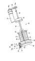
- the chuck unit 20 includes a chuck portion main body 38, a bracket 40, a gripping / rotating actuator 42, a clutch portion 44, a main shaft brake 46, a width extending actuator 48, and the like.
- the chuck body 38 is composed of, for example, a pair of chuck portions 38a and 38b (see FIGS. 9 and 12, etc.), and each of the chuck portions 38a and 38b can be expanded and contracted in the radial direction of the tire 28 using a link mechanism.
- a plurality of contact members 26 are provided.
- the tire 28 is gripped by expanding the diameter of the contact member 26 in a state of being inserted on the inner diameter side of the bead portion of the tire 28.
- the tire 28 is moved by moving the pair of chuck portions 38a and 38b in the width direction of the tire 28 (the pair of chuck portions 38a and 38b are relatively separated from each other) while the contact member 26 holds the tire 28. Apply a tension in the width direction to correct the shape (outer shape) for inspection.
- the bracket 40 is supported by the elevating bracket 22a shown in FIG. 1 and supports the entire chuck unit 20.
- the bracket 40 is provided with an actuator such as a motor (not shown), a gear device, and the like, and by driving the actuator, the bracket 40 and the chuck 40 support the chuck unit body 38 together with the actuator, and the grip / release posture position of the tire 28 is set. Turn between inspection posture positions.
- the gripping / rotation actuator 42 rotates the drive shaft 50 connected to the clutch portion 44 to expand / contract the abutting member 26 of the chuck portion main body 38 and rotate the entire chuck portion main body 38 (gripping the tire 28). Rotating motion with a fixed posture). The operations of the gripping / rotating actuator 42 and the clutch portion 44 and the behavior of the chuck body 38 will be described later.
- the spindle brake 46 releases the brake when the entire chuck unit body 38 rotates in a posture in which the tire 28 is gripped, and allows the entire chuck unit body 38 to rotate.
- the main shaft brake 46 generates a braking force that stops the rotation of the entire chuck portion body 38 when the contact member 26 is expanded or contracted.
- the spindle brake 46 may be a type that operates a latch or a gear, or may be a type that operates an electromagnetic brake.
- the width expansion actuator 48 is configured by, for example, a motor or the like, and rotates a drive shaft 48a to move a pair of chuck portions 38a and 38b (chuck base plates described later) in contact with and separate from each other.
- a pair of chuck portions 38a and 38b chuck base plates described later
- the bead portion of the tire 28 gripped by the plurality of circumferentially arranged contact members 26 in the chuck portions 38 a and 38 b is expanded in the width direction of the tire 28.
- a predetermined tension is applied to both side surfaces of the tire 28, the shape of the side surface is stabilized (corrected for inspection), and it can contribute to the reduction of inspection noise caused by the shape.
- the chuck body 38 is composed of a pair of chuck portions 38a and 38b as described above.
- the chuck portion 38 a includes, for example, a plurality of link mechanisms 52 on a substantially circular plate-like chuck base plate 54 in a circumferential shape, and the link mechanisms 52 respectively expand and contract the corresponding contact members 26.
- the chuck portion 38b includes, for example, a plurality of link mechanisms 52 having a configuration similar to that of the link mechanism 52 on the chuck base plate 54 on a substantially circular plate-like chuck base plate 94 (see FIG. 8). The link mechanisms 52 expand or contract the corresponding contact members 26.
- the chuck part 38a (chuck base plate 54) and the chuck part 38b (chuck base plate 94) are arranged in parallel in the width direction of the tire 28 (see FIG. 1).
- one chuck portion 38a may be referred to as a first chuck portion or a lower chuck portion
- the chuck base plate 54 may be referred to as a first chuck portion or a lower chuck portion.
- the other chuck portion 38b of the pair may be referred to as a second chuck portion or an upper chuck portion
- the chuck base plate 94 may be referred to as a second chuck portion or an upper chuck portion.
- the chuck base plate 54 constituting the chuck portion 38a (first chuck portion) is shown, and the chuck base plate 94 constituting the chuck portion 38b (second chuck portion) is omitted from the illustration. Only the mechanism 52 and the contact member 26 are shown.
- the chuck base plate 54 located on the tip side of the drive shaft 50 is referred to as the outer (front side) chuck base plate 54, and the chuck base plate (not shown) closer to the gripping / rotating actuator 42 is located on the inner side (rear side). Side) chuck base plate 94.
- the chuck portion main body 38 moves the plurality of contact members 26 in the radial direction and the width direction of the tire 28 in order to grip the tire 28.
- the radial movement operation of the tire 28 in the contact member 26 is realized by the grip / rotation actuator 42 that functions as a first drive mechanism and the drive shaft 50 that is rotationally driven thereby.
- the grip / rotation actuator 42 is stretched between a pulley 42 a fixed to the output shaft of the grip / rotation actuator 42 and a pulley 50 a fixed to the end of the drive shaft 50.
- the driving force of the gripping / rotating actuator 42 is transmitted to the driving shaft 50 by the driving belt 56.
- the drive shaft 50 is connected only to the outer chuck base plate 54 (chuck portion 38a) side.
- the movement operation of the tire 28 in the width direction in the contact member 26 is transmitted to the chuck unit body 38 via the width expanding actuator 48 that functions as a second drive mechanism and the drive shaft 48a that is rotationally driven thereby.
- the inner chuck base plate 94 (chuck portion 38b; see FIG. 8) indirectly supports the chuck base plate 94 with respect to the outer chuck base plate 54 (chuck portion 38a) by the driving force of the width expansion actuator 48.
- the first drive mechanism and the second drive mechanism may be collectively referred to as a drive mechanism.
- the structure of the link mechanism 52 that operates the contact member 26 supported by the chuck base plate 54 (chuck portion 38a) will be described with reference to FIGS. In FIG. 5, one set of the link mechanism 52 is illustrated, and the other three sets are not illustrated. Further, since the structure of the link mechanism 52 for operating the contact member 26 of the chuck base plate 54 and the chuck base plate 94 (chuck portion 38b; see FIG. 8) is substantially the same, the structure of the chuck base plate 54 (chuck portion 38a) is representative. To explain.
- the link mechanism 52 includes a plurality of disk-shaped plates and link arms.
- a first link plate 58 that is rotatably supported by a chuck base plate 54 is fixed to one end of a drive shaft 50 that is rotated by a gripping / rotating actuator 42.
- the first link plate 58 has, for example, a substantially disk shape, and supports the link mechanism 52 in the vicinity of the outer edge at substantially equal intervals.
- the first link plate 58 is required when the tire 28 is rotated (when shooting for inspection), that is, when the link mechanism 52 is in the gripping state maintaining posture, and the required rotation speed of the tire 28 (revolving speed required for shooting for inspection). Rotate all around.
- the link mechanism 52 includes a first link arm 60, a second link plate 62, a second link arm 64, a third link arm 66, a base plate 68, a contact member 26, and the like.
- the first link arm 60 is, for example, a substantially rectangular plate-like member, and one end is rotatably supported in the vicinity of the outer edge portion of the first link plate 58, and the other end is rotatable in the vicinity of the outer edge portion of the second link plate 62. It is supported by.
- the second link plate 62 is, for example, a substantially disk-shaped component, and is rotatably supported on a chuck base plate 54 (not shown) (see FIG. 3).
- the second link plate 62 rotatably supports one end of the second link arm 64 at a position facing the position where the first link arm 60 is connected, for example, with the rotation center 62a interposed therebetween.
- the attachment positions of the first link arm 60 and the second link arm 64 on the second link plate 62 are appropriately selected according to the operation mode (operation stroke) required for the link mechanism 52.
- An interlocking shaft 70 is fixed to the rotation center 62 a of the second link plate 62.
- the interlocking shaft 70 is fixed to the rotation center 62a of the second link plate 62 and is attached to the chuck base plate 54 so as to rotate in conjunction with the rotation of the second link plate 62 accompanying the rotation of the first link plate 58. It is supported rotatably via a bearing or the like.
- the interlocking shaft 70 As the interlocking shaft 70 rotates, the contact member 26 supported by the chuck base plate 94 (see FIG. 8) (not shown) is expanded or contracted. Further, as described above, the interlocking shaft 70 functions as a guide member when the chuck base plate 54 and the chuck base plate 94 (see FIG. 8) are separated, and the bead portion of the tire 28 is expanded in the width direction. Contributes to the stabilization of The interlocking shaft 70 also functions as a rotational force transmission member when the entire chuck portion main body 38 is rotated for photographing the surface of the tire 28.
- the second link arm 64 is, for example, a substantially rectangular plate-like member, one end of which is rotatably supported in the vicinity of the outer edge portion of the second link plate 62, and the other end is deviated from the central portion of the third link arm 66. Is supported rotatably.
- the third link arm 66 is, for example, a substantially rectangular plate-like member, and one end of the third link arm 66 is connected to a bearing 66a fixed in the vicinity of the outer edge of the chuck base plate 54 (not shown) and is rotatable. It is supported.
- the other end of the third link arm 66 supports a base plate 68 (swing member) that supports the contact member 26 so as to be rotatable (swingable).
- the third link arm 66 swings around the bearing 66 a when the second link arm 64 is operated, and presses the contact member 26 against the bead portion of the tire 28.
- a spring 72 that functions as an urging member is fixed to the third link arm 66.
- the other end of the spring 72 is connected to a part of the base plate 68 that supports the abutting member 26, and draws one side (the second abutting member 76, 76a side) of the base plate 68 toward the bearing 66a in a steady state.
- the base plate 68 is, for example, a substantially rectangular plate-like member, and supports a first contact member 74 and a second contact member 76 that function as the contact member 26 at both ends in the longitudinal direction.
- the biasing force of the spring 72 keeps the base plate 68 in the predetermined biasing posture described above, and avoids the second abutting member 76 from abutting on the bead portion before the first abutting member 74. is doing.
- the means for generating the urging force for avoiding the second abutting member 76 from abutting on the bead portion before the first abutting member 74 is not limited to the spring 72, and may be realized by, for example, a link mechanism. It may be realized by using an actuator, and the same effect can be obtained.
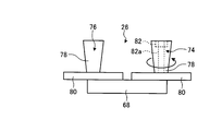
- FIG. 6 is a plan view for explaining the shape of the contact member 26 (first contact member 74 and second contact member 76) of the link mechanism 52 (see FIG. 5) provided on the chuck base plate 54 (chuck portion 38a).
- the figure is shown.
- the first contact member 74 and the second contact member 76 have substantially the same outer shape, and a main body 78 that is a truncated cone having a tapered portion (tapered surface), and a disk connected to the smaller diameter side of the main body 78. It is comprised with the shape-like flange part 80.
- FIG. The first contact member 74 and the second contact member 76 included in the link mechanism 52 provided on the chuck base plate 54 are connected to the base plate 68 on the flange portion 80 side.
- the first abutting member 74 has, for example, a rotation mechanism that uses a bearing 82 disposed therein, and is rotatable around a rotation shaft 82 a fixed to the base plate 68.
- the second contact member 76 is fixed to the base plate 68 and is not rotated.
- the biasing force of the spring 72 pulls the second contact member 76 side toward the bearing 66a and the contact member 26 comes into contact with the bead portion of the tire 28, the first contact member 74 is always in contact with the first contact member 74. It is comprised so that it may contact
- the chuck body 38 further expands in diameter and the second contact member 76 contacts the bead portion (first stage). 1 contact stage) is formed.
- first contact stage the first contact member 74 that is in contact with the bead portion rotates as the chuck body 38 expands in diameter.
- the contact position between the first contact member 74 and the bead portion of the tire 28 can be relatively changed.
- the first abutting member 74 abuts in a relative movement permitting state in which the relative movement of the abutting position is possible (allowed) in the first abutting stage.
- the contact member 26 does not contact the bead portion in a relative movement allowable state.
- the gripping operation is started in a state in which the machine center position of the chuck body 38 (for example, the center of the first link plate 58) is shifted from the center position of the tire 28 stopped on the stop station 14 (see FIG. 1). ).
- some of the contact members 26 of the plurality of contact members 26 included in the chuck portion main body 38 come into contact with the bead portion of the tire 28 closest to the machine center position of the chuck portion main body 38.
- the pressing force in the direction in which the tire 28 is moved so as to align the center position of the tire 28 with the machine center position of the chuck body 38 is applied from the contact member 26 to the bead portion.
- the pressing force for sliding the tire 28 on the stop station 14 may concentrate on a part of the bead portion, and the shape of the tire 28 may be deformed (distorted).
- the deformation amount (strain) of the tire 28 changes according to the positional deviation amount between the chuck portion main body 38 and the tire 28 and the like.
- the pressing force can be dispersed by contacting in the state. That is, the stress concentration at the time of pressing can be relaxed and partial deformation (distortion) of the tire 28 can be suppressed. In this way, the tire 28 is moved on the stopping station 14 so that the machine center position of the chuck portion main body 38 and the center position of the tire 28 coincide with each other while suppressing the stress concentration.
- the second contact member 76 is brought into contact with the contact surface of the bead portion following the first contact member 74 in the second contact step following the first contact step. Since the second contact member 76 is fixed to the base plate 68, even if the chuck portion main body 38 performs a diameter expansion operation in a state where the second contact member 76 is in contact with the contact surface of the bead portion of the tire 28. Like the first contact member 74 described above, the bead portion is pushed and expanded in the diameter increasing direction without causing relative movement between the second contact member 76 and the bead portion of the tire 28. That is, in the second contact stage, the second contact member 76 contacts in a non-relative movement state that does not cause relative movement at the contact position.
- the entire contact member 26 enters a non-relative movement state, and the machine center position of the chuck portion main body 38 and the center position of the tire 28 are substantially matched.
- the bead portion can be gripped in a state of being centered. That is, the gripping of the tire 28 is completed with a well-balanced posture.
- FIG. 7 shows the contact members 26 (first contact member 74a and second contact member 76a) of the link mechanism 52 (see FIG. 5) provided on the chuck base plate 94 (chuck portion 38b; see FIG. 8).
- a plan view illustrating the shape is shown.
- the outer shapes of the first contact member 74 a and the second contact member 76 a for the chuck base plate 94 are similar to the first contact member 74 and the second contact member 76 for the chuck base plate 54.
- the length of the main body portion 78 of the first contact member 74a and the second contact member 76a is longer than that of the first contact member 74 and the second contact member 76.
- This difference in length is for smoothly performing a gripping operation by the abutting member 26 when performing a gripping procedure of the present embodiment to be described later, and it is not always necessary to make the length of the main body portion 78 different. It may be the same length. Further, depending on the gripping procedure, the length of the main body 78 of the first contact member 74 and the second contact member 76 may be longer than that of the first contact member 74a and the second contact member 76a.
- the main body portions 78 of the first contact member 74 a and the second contact member 76 a are also truncated cones, and a disk-shaped flange portion 80 is connected to the small diameter side of the main body portion 78.
- first abutting member 74 a and the second abutting member 76 a of the link mechanism 52 provided on the chuck base plate 94 are connected to the base plate 68 on the large diameter side (the side where the flange portion 80 is not coupled) of the main body portion 78.
- first contact member 74 a Similar to the first contact member 74, the first contact member 74 a has a rotation mechanism provided with a bearing 82 inside, and is rotatable around a rotation shaft 82 a fixed to the base plate 68.
- the abutting member 26 supported by the chuck base plate 94 abuts against the bead portion of the tire 28 by the rotation mechanism of the first abutting member 74a
- the abutting member 26 supported by the chuck base plate 54 is used.
- gripping in which stress concentration is suppressed is executed.
- the second contact member 76a is fixed to the base plate 68 and is not rotated.
- the bead portion can be gripped in a state where the machine center position of the chuck portion body 38 and the center position of the tire 28 are substantially coincident (centered state). That is, the gripping of the tire 28 is completed with a well-balanced posture.
- the interlocking shaft 70 for operating the contact member 26 of the chuck base plate 94 is, for example, a spline shaft having a spline groove 70a.
- a spline 84 is formed.
- a second link plate 86 and a chuck base plate 94 (not shown) are fixed to the end surface of the outer cylinder portion 84a.
- a third link arm 88 is rotatably supported by a chuck base plate 94 (not shown) via a bearing 88 a, and a second link arm 64 (not shown) is provided on the back side of the third link arm 88. It is connected.
- a base plate 68 is rotatably connected to one end of the third link arm 88, and a first contact member 74a and a second contact member 76a are supported on the base plate 68 (see FIG. 7). Therefore, the second link plate 86 and the chuck base plate 94 (not shown), the third link arm 88 supported by the chuck base plate 94, the base plate 68, the first contact member 74a, the second contact member 76a, etc. It becomes possible to move in the axial direction of the interlocking shaft 70 together with the outer cylinder portion 84a.
- the drive shaft 48 a of the width expansion actuator 48 shown in FIG. 2 is connected to, for example, the chuck base plate 94. As a result, the width expanding operation is realized by moving the chuck base plate 94 in the width direction of the tire 28 by driving the width expanding actuator 48.
- the link mechanism 52 configured as described above can take two modes: a grip state in which the tire 28 is gripped by rotation of the drive shaft 50, that is, rotation of the first link plate 58, and a release state in which the grip is released.
- FIG. 3 shows a case where the link mechanism 52 is in the released state of the tire 28
- FIG. 4 shows a case where the link mechanism 52 is in the gripped state of the tire 28.
- the contact member 26 is further closer to the inner diameter side than the minimum diameter S of a predetermined amount smaller than the rim diameter TS of the minimum tire size that can be inspected by the tire inspection device 10.
- the link mechanism 52 is contracted so that the (first contact member 74 and second contact member 76) are positioned (a reduced diameter state).
- the chuck body 38 can smoothly enter the inner diameter side of the bead portion of the tire 28 for gripping or releasing the tire 28.
- the link mechanism 52 as shown in FIG. 3 is in a reduced diameter state, the base plate 68 that supports the second contact member 76 is maintained in the first posture by the urging force of the spring 72.
- the second contact member 76 is separated from the bead portion so that the first contact member 74 is in contact with the contact surface of the bead portion in advance of the second contact member 76. is there. Further, as shown in FIG.
- the link mechanism 52 extends so that the member 26 (first contact member 74, second contact member 76) is positioned.
- the base plate 68 swings against the urging force of the spring 72 and shifts to the second posture, and the second contact member 76 contacts the bead portion and securely holds the tire 28.
- the tire 28 can be lifted and the posture can be changed and rotated safely and smoothly.
- the inspectable tire size of the tire inspection apparatus 10 of the present embodiment can be set to 14 inches and 15 inches, for example.
- the extension amount of the link mechanism 52 can be controlled in accordance with the rotation amount of the first link plate 58 (drive shaft 50).
- the rotation of the first link plate 58 may be controlled so as to be the first extension amount
- the rotation of the first link plate 58 may be controlled so as to be the second extension amount.
- the rotation control of the first link plate 58 (drive shaft 50) can be realized by, for example, the rotation speed control or torque control of the grip / rotation actuator 42.
- the grip / rotation actuator 42 may be controlled based on the extension amount of the link mechanism 52.
- the transmission mode of the driving force of the gripping / rotating actuator 42 can be switched by the clutch portion 44 (see FIG. 2). That is, the clutch unit 44 switches between the gripping operation force transmission state and the rotational operation force transmission state.
- the gripping operation force transmission state is a state in which power for realizing the expansion / contraction operation of the abutting member 26 of the chuck portion main body 38 is transmitted from the gripping / rotating actuator 42 side.
- the rotational operation force transmission state is a state in which power for realizing rotation of the entire chuck portion main body 38 (rotation in a posture in which the tire 28 is gripped) is transmitted from the grip / rotation actuator 42 side.
- a plurality of contact members 26 are disposed on the chuck base plates 54 and 94, respectively, as shown in FIG. 3 and the like. In FIG. 8 and FIG. Therefore, only one set of the contact member 26 (link mechanism 52) is shown on the chuck base plates 54 and 94, respectively.
- a clutch portion 44 is disposed at a predetermined position on the drive shaft 50, for example, near the intermediate position. The clutch unit 44 can switch the connection / disconnection state at a predetermined timing, for example, by applying a voltage based on a command from the control panel 1000.
- the clutch unit 44 may be configured to switch the connection / disconnection state by controlling an actuator such as a solenoid, a motor, or a fluid pressure cylinder.
- an actuator such as a solenoid, a motor, or a fluid pressure cylinder.
- the clutch portion 44 When in the connected state, the clutch portion 44 mechanically connects the drive shaft 50 and the pipe-shaped rotation main shaft 90 containing the drive shaft 50 to rotate integrally.
- the clutch portion 44 when the clutch portion 44 is in a disconnected state, the mechanical connection between the drive shaft 50 and the rotary main shaft 90 is canceled, and only the drive shaft 50 rotates. In this case, the rotation spindle 90 is locked (non-rotation state) by applying a braking force by the spindle brake 46 (see FIG. 2).
- the drive shaft 50 realizes the expansion / contraction operation of the contact member 26 of the chuck base plate 54 and the contact member 26 of the chuck base plate 94.
- a guide plate 92 that supports a plurality of (for example, four) interlocking shafts 70 so as to be rotatable and slidable in the axial direction is fixed to the rotating main shaft 90.
- the guide plate 92 supports a plurality of (for example, four) guide shafts 96 fixed to the chuck base plate 94 so as to be slidable in the axial direction.
- the clutch portion 44 mechanically connects the drive shaft 50 and the pipe-shaped rotation main shaft 90 containing the drive shaft 50 to rotate integrally.
- the spindle brake 46 (see FIG. 2) that applies a braking force to the rotating spindle 90 is released and allows the rotating spindle 90 to rotate.
- the guide plate 92 supports the plurality of interlocking shafts 70 and the guide shaft 96 so as to be slidable in the axial direction. As a result, when the guide plate 92 rotates integrally with the rotation main shaft 90, the chuck base plate 54 that supports the interlocking shaft 70 rotates.
- the chuck base plate 94 to which the guide shaft 96 is fixed rotates.
- the drive shaft 50 rotates together with the rotation main shaft 90
- the state in which the driving force in the expanding direction is applied to the contact member 26 of the chuck base plate 54 and the chuck base plate 94 is continued.
- the entire chuck unit main body 38 rotates with the gripping force maintained. That is, the tire 28 rotates together with the chuck portion main body 38.
- the chuck base plate 94 supports the interlocking shaft 70 to be slidable in the axial direction
- the guide plate 92 supports the interlocking shaft 70 and the guide shaft 96 to be slidable in the axial direction.
- the chuck base plate 94 can be moved toward and away from the chuck base plate 54 by the width extending actuator 48.
- the contact member 26 of the chuck base plate 54 and the contact member 26 of the chuck base plate 94 can be expanded in the width direction of the tire 28 while maintaining the gripping state. That is, the chuck portion main body 38 can execute rotation of the tire 28 while maintaining a posture in which the tire 28 is gripped in the radial direction and the width direction.
- the chuck portion main body 38 starts gripping the tire 28
- the chuck portion main body 38 (chuck portion 38a, chuck portion 38b) is in the reduced diameter state shown in FIG. Enter the opening 100 defined on the inside.
- the first link plate 58 is rotated by a predetermined angle in the arrow A direction (counterclockwise direction) by the grip / rotation actuator 42 and the drive shaft 50 that function as the first drive mechanism. Let By this rotation, the first link arm 60 moves in the direction of arrow B, the second link plate 62 rotates in the direction of arrow C (counterclockwise direction), and the second link arm 64 moves in the direction of arrow D.
- the third link arm 66 swings outward in the radial direction of the tire 28 around the bearing 66a, and the first contact member 74 supported by the base plate 68 is urged outward in the tire radial direction (arrow E). Is done.
- This stage is called the first contact stage.
- the first contact member 74 is rotatably supported by the base plate 68. Accordingly, even when the machine center position of the chuck portion main body 38 and the center position of the tire 28 do not coincide with each other, the first abutting member 74 rotates to change the relative position with the bead portion, so that the tire 28 is stopped. 14 (see FIG. 1) is moved (slided).
- the chuck portion body 38 corrects the deviation of the center position while relaxing the stress concentration during the movement of the tire 28.
- the base plate 68 is shifted to the first posture by the spring 72 (see FIG. 3), and the second contact member 76 is moved from the bead portion (opening portion 100). The separated state is maintained.
- the base plate 68 is configured such that the first contact member 74 contacts the contact surface of the bead portion before the second contact member 76.
- the second contact member 76 that does not rotate (the second contact member 76 in a non-relative movement state) contacts the contact surface of the bead portion and deforms the tire 28. It prevents you from letting it go.
- the second posture of the base plate 68 is a posture that shifts from the first posture of the base plate 68 shown in FIG. 10 as the drive shaft 50 (first link plate 58) continues to rotate.
- first link plate 58 is further rotated in the direction of arrow A
- first link arm 60 is further moved in the direction of arrow B
- second link plate 62 is further rotated in the direction of arrow C
- the second link arm 64 is moved. Further, it is moved in the direction of arrow D.
- the first contact member 74 already supported by the base plate 68 at one end is in contact with the bead portion (opening portion 100). Accordingly, the base plate 68 swings against the spring 72 (see FIG. 4), and the second contact member 76 that does not rotate contacts the bead portion (opening portion 100), so that the outer side in the tire radial direction (arrow E). Giving an urging force to This stage is referred to as a second contact stage.
- the contact members 26 presses the inner diameter of the bead portion (opening portion 100) almost evenly over the entire circumference. That is, the tire 28 can be firmly gripped without causing partial deformation of the tire 28.
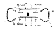
- FIG. 12 is a schematic diagram for explaining how the contact member 26 expands in the width direction of the tire 28 after the base plate 68 of the chuck body 38 has completed the transition to the second posture shown in FIG.
- the contact member 26 first contact member 74, second contact member 76 supported by the chuck base plate 54 (chuck portion 38a) is shown on the right side of the drawing, and the chuck base plate 94 (chuck) is shown on the left side of the drawing.
- the contact member 26 (the first contact member 74a and the second contact member 76a) supported by the portion 38b) is shown. Further, the taper portion of the main body portion 78 of the contact member 26 is omitted for simplification of the drawing.
- the abutting member 26 has a flange portion 80 at one end of the main body portion 78, the bead toe 102 a among the bead toe 102 a inside the tire 28 and the bead heel 102 b outside the tire 28 constituting the bead portion 102.
- the flange portion 80 can be easily brought into contact with the inner side in the width direction of the tire 28 at the bead portion 102.
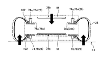
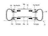
- the chuck base plate 94 (see FIG. 8) that supports the first contact member 74a and the second contact member 76a is chucked by the width expanding actuator 48 and the drive shaft 48a (see FIG. 2) that function as the second drive mechanism. Separated from the base plate 54. As a result, as shown in FIG.
- the first contact member 74 and the second contact member 76 supported by the chuck base plate 54, and the first contact member 74a and the second contact member 76a supported by the chuck base plate 94. Is relatively spaced apart and expands the tire 28 in its width direction. Since the bead wire 102c in which steel wires or the like are bundled is present inside the bead portion 102, the bead toe 102a of the bead portion 102 and the flange portion 80 are engaged with each other by appropriately selecting the size of the flange portion 80. It is possible to achieve a smooth expansion operation.
- the tire gripping device 16 grips the tire 28 while centering in two stages of the first contact stage and the second contact stage, and extends in the tire width direction while maintaining the grip state. .
- the tire 28 to be gripped is supported in a balanced manner toward the outside in the radial direction with a substantially uniform pressing force (gripping force) with reference to the center position of the tire 28.
- movement can be suppressed.
- the shape of the side surface of the tire 28 may be deformed by its own weight, resulting in variations in the shape of the same type of tire 28, which may affect the inspection accuracy.
- the degree of curvature of the side surface of the tire 28 can be corrected by expanding in the tire width direction while maintaining the gripping posture of the contact member 26 in the radial direction. Then, by extending the width of the tire 28 to the set value, the measurement conditions by the inspection unit 18 can be unified and the state of the detection surface (inspection surface) can be made uniform. As a result, noise contamination in the inspection image (tire image) taken by the inspection unit 18 can be reduced, which can contribute to improvement in inspection accuracy.
- FIG. 13 is a view showing a state in which the tire 28 that has been gripped / expanded by the contact member 26 is rotated together with the chuck portion main body 38 for inspection by the inspection unit 18.
- the clutch portion 44 (see FIG. 9) is switched to the connected state, and the driving force of the gripping / rotating actuator 42 is applied to the chuck base plate 94 via the rotary spindle 90. And transmitted to the chuck base plate 54.
- the chuck portion main body 38 can rotate the tire 28 at a predetermined speed, for example, in the arrow R direction while maintaining the gripping state.
- three imaging units (imaging apparatuses) constituting the inspection unit 18 image the tread surface and both side surfaces of the rotating tire 28 and perform an inspection on the shape, surface scratches, dirt, and the like of the tire 28.
- steps and patterns called splices and pradders on the inner surface of the tire 28. Therefore, for example, in the case of a system in which the gripping portion of the chuck device is a tire rotation drive source, vibration may occur each time the gripping portion passes through a splice or a portion of a ladder. That is, the vibration may deteriorate the quality of the inspection image.
- the chuck portion main body 38 of the present embodiment grips the tire 28 and rotates as a whole while maintaining the gripped state, so that vibrations caused by splices and pradders do not occur. This can also contribute to improvement of inspection quality and accuracy.
- the contact member 26 is in direct contact with the tire 28 in the chuck body 38.
- the tire 28 is formed in a ring shape by winding a flat rubber material including fibers and metal wires, but “burrs” may remain at the open end, for example, the tip of the bead.
- burrs may remain at the open end, for example, the tip of the bead.
- the contact member 26 forms a recessed portion that receives (accommodates) a burr when a burr is present at the tip of the bead portion.
- the hollow portion may be a small diameter portion 78 b having a smaller diameter than the tapered portion 78 a that is the side surface of the main body portion 78.
- the main body part 78 When the main body part 78 is provided with a hollow part, most of the end surface of the bead part comes into contact with the tapered part 78a (large diameter part, non-dent part) of the main body part 78. On the other hand, the burr protruding from the end surface (end portion in the tire radial direction) of the bead portion does not affect the contact between the end surface of the bead portion and the side surface portion of the main body portion 78 by fitting into the recessed portion of the small diameter portion 78b. become. Further, by providing the small-diameter portion 78b as shown in FIG.
- the burr receiving effect of the bead portion is improved, and the engagement strength when the tire 28 is expanded in the width direction by the flange portion 80 is improved. This can contribute to the improvement of operation reliability.
- the tapered portion 78a is formed, it has been confirmed by various tests that the taper angle is preferably about 5 ° to 9 °, for example.
- FIG. 15 is an explanatory view for explaining a contact state between the bead portion and the contact member 26.
- the small diameter portion 78b of FIG. 14 is omitted.
- various shapes of the bead portion 102 exist depending on the type of the tire 28.
- the tapered portion 78a that receives the burr of the bead portion 102 absorbs inconsistency due to the difference in the shape of the tip portion of the bead portion 102 due to the difference in the type of the tire 28, and realizes reliable engagement and gripping. be able to.
- the contact member 26 may be the same regardless of the type of the tire 28, and the shape of the tapered portion 78 a may be the same, or the taper angle may be changed according to the type of the tire 28 to be gripped. . In this case, the contact state between the bead portion and the contact member 26 can be more closely adhered, and the gripping performance can be improved.
- the inspection unit 18 of the present embodiment photographs the surface of the tire 28 with the photographing unit while illuminating the tire 28 with the light irradiation unit.
- a laser light sheet can be used as the light irradiation unit.
- the laser light sheet hits a portion other than the tire 28, for example, the contact member 26 that directly contacts the tire 28.
- the reflected light reflected by the contact member 26 or the like may enter the imaging region when the tire 28 is captured. If reflected light is mixed in the photographed image, it becomes noise. Therefore, in the case of this embodiment, as shown in FIG.
- the surface of the main body portion 78 of the contact member 26 is subjected to reflection suppression processing.
- the reflection suppression treatment for example, a surface treatment using black chrome plating or the like can be used.
- the reflection suppressing process is not limited to black chrome plating or the like, and the same effect can be obtained even if a process for suppressing irregular reflection is performed by applying a paint capable of suppressing reflection, forming a film, surface processing, or the like.
- the reflection suppression processing may be performed on the entire contact member 26 (the side surface of the main body portion 78 and the upper surface and the flange portion 80 where the flange portion 80 is not connected), but the flange portion 80 is the bead portion of the tire 28. Since it hides inside, you may give only to the main-body part 78 part (a side surface and an upper surface).
- FIG. 17 shows another embodiment of the contact member 26.
- the first contact member 74 of the contact member 26 is stress-concentrated by bringing the bead portion and the first contact member 74 into contact with each other in a relative movement allowable state in the first contact stage. Therefore, the tire 28 is prevented from being deformed.
- the first contact member 74 of the present embodiment is subjected to rotation induction processing on the surface of the main body portion 78 of the first contact member 74 that is configured to be rotatable. As the rotation induction processing, an uneven groove in a direction perpendicular to the rotation direction of the first abutting member 74 as shown in FIG.
- the rotation induction processing is performed by forming irregular irregularities or increasing the surface roughness (processing to reduce the smoothness of the surface or processing to reduce the smoothness by covering with resin such as rubber). May be.
- the concave and convex grooves and the concave and convex portions may be provided at the same time as the main body portion 78 is formed, or may be provided by post-processing after the main body portion 78 is formed.
- the first abutting member 74 surely rotates, so that the second abutting member 76 has a predetermined timing (before completion of centering of the tire 28). ) To the bead portion can be suppressed.
- the rotation induction processing is performed on the main body portion 78 of the first abutting member 74, depending on the type of processing, there is a possibility of causing irregular reflection when light from a light irradiation unit or the like is applied. That is, it may cause noise in the inspection image. Therefore, as shown in FIG.
- the contact region P between the bead portion 102 and the main body portion 78 of the first contact member 74 is confirmed in advance by an experiment or the like, and rotation induction processing is performed only on the contact region P. It is desirable that the other part (the end surface Q of the first abutting member 74 or the flange portion 80) be subjected to a reflection suppressing process.
- the tire inspection apparatus 10 turns the chuck unit 20 downward 90 ° from the state of FIG. 1 so that the lower chuck portion 38a (chuck base plate 54) of the chuck unit 20 faces the conveyance surface of the stop station 14. It is assumed that the acceptance of the tire 28 is awaited in the inspection start posture.
- the control unit of the tire inspection apparatus 10 executes the following control by reading the control program stored in the ROM and executing it on the RAM when the tire is started.
- the control unit of the tire inspection apparatus 10 determines whether the tire 28 to be inspected has reached the tire gripping position of the stop station 14 from the previous process based on a signal from a senna (not shown) arranged around the stop station 14.
- the process which determines whether is performed (S100). When the tire 28 has not reached the tire gripping position (No in S100), this flow is once terminated and the tire 28 waits for the tire 28 to reach the tire gripping position.
- S100 when it can be confirmed by a signal from the sensor that the tire 28 has reached the tire gripping position (Yes in S100), as shown in FIG.
- the control unit lowers the chuck unit 38a (chuck base plate 54).
- a process for adjusting the grip position is executed (S102).
- the abutting member 26 (first abutting member 74) supported by the chuck base plate 54 is configured so that the bead toe 102a of the bead portion 102 on the stopping surface side of the stopping station 14 (the inside of the tire 28 in the bead portion 102). It is an adjustment that makes it possible to come into contact with the open end portion of the. This adjustment is performed by moving the entire chuck unit 20 toward the stop surface of the stop station 14 by the lifting mechanism 22.
- the movement control amount at this time may be executed by detecting the distance from the chuck base plate 54 to the stationary surface of the stationary station 14 or the distance to the lower (being stationary station 14 side) bead unit 102, or by performing a test beforehand. You may control by the descent distance to the stop surface of the fixed stop station 14 defined. Subsequently, as shown in FIG. 21, the control unit executes processing for adjusting the gripping position of the upper chuck unit 38b (chuck base plate 94) (S104). In this adjustment, the contact member 26 (first contact member 74a) supported by the chuck base plate 94 is a bead toe 102a (the tire 28 of the bead portion 102) of the bead portion 102 on the side far from the stop surface of the stop station 14.
- This adjustment can be performed by separating the chuck base plate 94 from the chuck base plate 54 by the width expansion actuator 48 (expanding in the width direction of the tire 28).
- the expansion control amount at this time can be determined by measuring in advance the interval between the bead portions 102 facing in the width direction of the tire 28 to be inspected. Further, the expansion control amount may be determined by detecting the position of the bead toe 102a of the bead unit 102 using a sensor or the like.
- the contact members 26 of the chuck portion 38a (chuck base plate 54) and the chuck portion 38b (chuck base plate 94) are shifted to the first contact stage. That is, the diameter of the main body portion 78 of the contact member 26 is expanded to the first diameter-expanded position so as to be in the state of FIG. 10 (S106). Then, the first abutting member 74 (74a) and the bead portion 102 are brought into contact with each other in a relative movement allowable state, and the centering of the tire 28 is executed (centering step). The movement to the first enlarged diameter position is executed by controlling the rotation of the first link plate 58 by the grip / rotation actuator 42 (No in S108).
- the control unit If the control unit considers that the first contact member 74 (74a) has reached the first diameter-expanded position (Yes in S108), in other words, if it is determined that centering of the tire 28 has been performed, The contact state of the contact member 26 is shifted to the second contact stage. That is, the control unit moves the second contact member 76 (76a) to the first diameter-enlarged position so as to end the relative movement between the main body portion 78 of the contact member 26 and the bead portion 102 (tire radial direction end portion). The process of moving to (S110) is executed. In this case, the control unit executes a process of further rotating the first link plate 58 in the link diameter increasing direction by the gripping / rotating actuator 42.
- the second contact member 76 (76a) contacts the bead portion 102 in a non-relative movement state, and thus the relative movement between the two ends.
- the tire 28 is temporarily fixed (temporarily gripped) by the second contact member 76 (76a) in a state where the centering is performed on the chuck portion main body 38 (temporary fixing step).
- the movement of the abutting member 26 to the first enlarged diameter position is not intended to grip the tire 28 but is mainly intended to center the tire 28 with respect to the chuck portion main body 38. Therefore, the control amount of the grip / rotation actuator 42 is smaller than the control amount when the tire 28 is gripped with the final gripping force.
- Completion of the movement to the first enlarged diameter position may be detected by the actual movement amount of the first contact members 74 and 74a and the movement amount of the second contact members 76 and 76a. Alternatively, it may be detected by a torque value in the grip / rotation actuator 42 or the like. When the movement amount is controlled based on the torque, when the torque reaches, for example, 6 to 8 kgf, it can be considered that the contact member 26 has completed the movement to the first diameter-expanded position.
- the control unit of the tire inspection apparatus 10 is configured so that the abutting member 26 of the chuck portion 38b (chuck base plate 94) is in a state in which the tire 28 is temporarily gripped by the abutting member 26 radially expanded (centering state).
- a process of pressing the flange portion 80 against the bead toe 102a of the upper bead portion 102 is executed (S112). That is, as shown in FIG. 23, the expansion process of the upper chuck portion 38 b is performed in which the chuck base plate 94 is separated from the chuck base plate 54 by a predetermined distance by the driving force of the width expansion actuator 48.
- the weight of the tire 28 acts, and the bead toe 102a of the bead part 102 is formed in a recessed part (taper part 78a) formed in the first contact member 74a and the second contact member 76a. , And is pushed into the small diameter portion 78b). That is, the contact state (gripping state) is improved together with the relative expansion operation of the tire 28 in the width direction.
- the tire 28 is moved from the stopping station 14 by the expansion in the tire width direction (bead width direction) by the flange portion 80 of the first contact member 74a and the flange portion 80 of the second contact member 76a of the chuck portion 38b.
- the control unit of the tire inspection apparatus 10 executes a process of pressing the flange portion 80 of the contact member 26 of the chuck portion 38a (chuck base plate 54) against the bead toe 102a of the lower bead portion 102 (S114).
- an expansion process of the lower chuck portion 38a for lowering the entire chuck unit 20 by a predetermined amount toward the stop station 14 is performed using the lifting mechanism 22 (see FIG. 1). .
- the bead toe 102a of the bead part 102 is pushed into the recesses (tapered part 78a, small diameter part 78b) formed in the first contact member 74 and the second contact member 76.
- the contact state (gripping state) is improved while maintaining the state of the bead portion of the tire 28 expanded in the width direction (maintaining the expanded state).
- the contact state is Maintained.
- the pair of chuck portions 38 a and 38 b are respectively moved to the outer side in the width direction of the tire 28, and the bead toe 102 a (the inner end portion in the tire width direction) of the bead portion 102 is moved by the flange portion 80. Push outward in the width direction.
- the gripping force that is finally required is 10 kgf, for example, the gripping force is temporarily reduced to the required gripping force after being gripped with a larger gripping force (for example, 14 kgf). Stabilize power.
- the second diameter expansion position (the second diameter expansion position larger than the first diameter expansion position) that finally generates the necessary gripping force contacts the third diameter expansion position having a larger diameter.
- the member 26 is once moved (S116).
- the movement to the third enlarged diameter position is executed by controlling the rotation of the first link plate 58 by the grip / rotation actuator 42 (No in S118). Whether or not it has moved to the third diameter expansion position can be determined by the amount of movement of the contact member 26 or the control torque of the gripping / rotating actuator 42 or the like.
- the control unit executes a process of reducing the contact state of the contact member 26 to the second diameter-expanded position. (S120).
- the control unit controls the gripping / rotating actuator 42 until the diameter reduction is completed at the second diameter expansion position (No in S122), and the completion of the diameter reduction to the second diameter expansion position is the amount of movement of the contact member 26. If the control torque can be confirmed (Yes in S122), a process of moving the tire 28 to the photographing position is executed (S124).
- the movement of the gripped tire 28 to the photographing position is performed by turning the chuck unit 20 by 90 ° by the turning mechanism 24 (see FIG. 1) while raising the chuck unit 20 by the lifting mechanism 22.
- the control unit switches the clutch unit 44 to the connected state and rotates the chuck unit body 38 at a predetermined speed by the driving force of the grip / rotation actuator 42.
- the inspection unit 18 irradiates the rotating tire 28 with inspection light from the light irradiation unit, and images the tread surface and both side surfaces of the tire 28 by the imaging unit (imaging process; S128).
- the tire inspection apparatus 10 analyzes the inspection images of the tread surface and both side surfaces of the photographed tire 28 according to a predetermined procedure, and inspects the quality of the tire 28 (inspection step; S130).
- the control unit switches the clutch unit 44 to the disconnected state. Then, the chuck unit 20 is lowered by the lifting mechanism 22 and the chuck unit 20 is turned 90 ° by the turning mechanism 24 to return the tire 28 to the tire stopping position of the stopping station 14 (S132). After confirming that the tire 28 has landed on the stop station 14 with a sensor or the like, the gripping / rotating actuator 42 reduces the diameter of the contact member 26 to the minimum diameter reduction position shown in FIG. S134).
- the control unit of the tire inspection device 10 executes a process of sending the tire 28 from the stop station 14 to the non-defective product conveyor on the downstream side.
- the tire inspection device 10 turns on the error indicator lamp and executes a process of sending the tire 28 to a discharge conveyor different from the good product conveyor.
- the inspection result is transferred to the management apparatus as product data regardless of quality.
- the bead toe 102a of the bead portion 102 of the tire 28 (the open end portion inside the tire 28 of the bead portion 102) is contacted.
- the member 26 is abutted and gripped, distortion of the tire 28 can be reduced or suppressed.
- the generation of noise due to distortion and vibration due to the gripping of the tire 28 is suppressed, and the inspection accuracy of the tire 28 can be improved.
- the contact member 26 mounted on the chuck base plate 54 and the chuck base plate 94 of the chuck portion main body 38 includes the first contact member 74 of the rotation type and the second contact member 76 of the fixed type.
- the abutting member 110 shown in FIG. 26 has a rotatable main body with a brake.
- the brake can be, for example, an electromagnetic brake, but is not limited thereto.
- the brake is released and the rotation of the contact member 110 is allowed to realize a relative movement allowable state. That is, it functions similarly to the first contact member 74 (74a) described above.
- the contact member 110 in the second contact stage, the contact member 110 generates a braking force to prevent rotation and realize a non-relative movement state. That is, it functions similarly to the second contact member 76 (76a) described above. As a result, the same effect as that of the above-described embodiment can be obtained.
- the first contact member and the second contact member are fixed to a base plate 68 that is a swing member. That is, the first contact member does not have a rotation mechanism.
- the first abutting member having the non-rotating structure has a surface portion having a static friction coefficient smaller than the stopping friction coefficient of the surface portion of the second abutting member having the non-rotating structure in order to realize the relative movement allowable state.
- the non-rotating first contact member realizes a relative movement allowable state by sliding with respect to the bead portion in the first contact stage, and relieves stress concentration at the time of pressing so as to reduce the portion of the tire 28. Suppresses general deformation (distortion).
- the non-rotating second contact member having a larger coefficient of static friction than the surface portion of the non-rotating first contact member makes contact with the bead portion in a non-relative movement state without slipping, and has a desired gripping force. Is realized.
- the static friction coefficient of the 1st contact member of a non-rotating structure and a 2nd contact member can be suitably selected by the surface treatment of the surface part of each contact member. For example, the static friction coefficient can be changed by adjusting the surface roughness or the surface coating material.
- the outer shape of the contact member 26 is a truncated cone. This illustrates the truncated cone as a shape in which the contact state with the contact member 26 hardly changes even when the inch size of the tire 28 to be inspected is changed and the curvature of the open end of the bead portion 102 changes.
- the outer shape of the abutting member 26 is not limited to this, and the first abutting member may be any shape that can form a favorable relative movement allowable state with the bead portion.
- the 2nd contact member should just be a shape which can form a favorable non-relative movement state between bead parts.
- the number of link mechanisms 52 provided in each of the chuck base plate 54 and the chuck base plate 94 can obtain a sufficient effect, and is an example of four sets from the viewpoint of easy understanding of the structure.
- the number of link mechanisms 52 can be selected as appropriate. The larger the number of link mechanisms 52, the better the dispersion efficiency of the pressing force when expanding the diameter, and the distortion suppressing effect when gripping the tire 28 can be improved.
- the number of link mechanisms 52 arranged on the chuck base plate 54 (94) is increased, the individual link mechanisms 52 may be reduced in size and the rigidity may be reduced, and the durability of the apparatus may be reduced.
- the number of link mechanisms 52 to be placed is reduced, the size of each link mechanism 52 can be increased and the rigidity can be easily ensured.
- the dispersion efficiency of the pressing force is lowered, and the distortion suppressing effect at the time of gripping may be lowered. Therefore, it is desirable to select the number of the link mechanisms 52 in consideration of the distortion suppressing effect at the time of gripping, durability, and the like.
- the example in which the expansion / contraction operation of the contact member 26 and the rotation operation of the entire chuck unit main body 38 are realized by using only the grip / rotation actuator 42 by using the clutch unit 44 has been described.
- the expansion / contraction operation of the member 26 and the rotation operation of the chuck portion main body 38 may be realized by separate actuators.
- the tire gripping device 16 of this embodiment includes a chuck mechanism and a drive mechanism as an example.
- the chuck mechanism can be brought into contact with the open end portion of the bead portion 102 of the tire 28 and is allowed to move relative to the contact surface of the open end portion in the first contact stage, and continues to the first contact stage.
- a pair of chuck body bodies 38 in the width direction of the tire 28 are provided with a plurality of circumferentially arranged contact members 26 that are in a non-relative movement state with the contact surface in the second contact stage.
- the drive mechanism includes, as an example, a first drive mechanism that moves the contact member 26 in the radial direction of the tire 28 and a second drive mechanism that moves the pair of chuck portion main bodies 38 in the width direction of the tire 28.
- a first drive mechanism that moves the contact member 26 in the radial direction of the tire 28
- a second drive mechanism that moves the pair of chuck portion main bodies 38 in the width direction of the tire 28.
- the contact member 26 of the tire gripping device 16 of the present embodiment includes a first contact member 74 (74a) that contacts the contact surface in the first contact stage to realize a relative movement allowable state.
- the second abutting step may include a second abutting member 76 (76a) that abuts against the abutting surface and realizes a non-relative movement state following the first abutting member 74 (74a).
- the first contact member 74 (74a) that realizes the relative movement allowable state first contacts, and then the second contact member 76 (76a) that realizes the non-relative movement state.
- Abut it is possible to effectively reduce or suppress the distortion of the tire 28.
- first contact member 74 (74a) and the second contact member 76 (76a) of the tire gripping device 16 of the present embodiment are supported by a swing member (base plate 68) as an example.
- the swing member (base plate 68) has a first posture in which the first contact member 74 (74a) contacts the contact surface in advance of the second contact member 76 (76a), and the second contact member 76. (76a) may be in a second posture in which the contact surface is in contact with the contact surface.
- the first contact member 74 (74a) that contacts in the relative movement allowable state contacts the contact surface earlier than the second contact member 76 (76a) that contacts in the non-relative movement state,
- the tire 28 is centered and subsequently gripped by the second contact member 76 (76a).
- the first abutting member 74 (74a) of the tire gripping device 16 of the present embodiment may include a rotation mechanism for realizing a relative movement allowable state as an example.
- the first abutting member 74 (74a) smoothly moves relative to the abutting surface in the circumferential direction, effectively relieving stress concentration during pressing, and reducing the distortion of the tire 28. Or suppression can be realized.
- the surface of the main body 78 of the tire gripping device 16 of the present embodiment may be subjected to rotation induction processing.
- the contact member 26 of the tire gripping device 16 of the present embodiment includes, as an example, a main body portion 78 that contacts the end portion in the tire radial direction of the bead portion 102, and the main body portion 78 connected to the main body portion 78. And a flange portion 80 that contacts the inner end portion in the tire width direction.
- a main body portion 78 that contacts the end portion in the tire radial direction of the bead portion 102
- the main body portion 78 connected to the main body portion 78.
- a flange portion 80 that contacts the inner end portion in the tire width direction.
- the main body part 78 of the tire gripping device 16 of the present embodiment may have, as an example, a hollow part (small diameter part 78b) that receives an end part in the tire radial direction in an end part region on the connection side with the flange part 80. Good.
- the main body portion 78 can smoothly guide the tip of the bead portion 102 to the position of the flange portion 80.
- the hollow portion can reliably receive the “burrs” and contribute to the improvement of the gripping stability of the bead portion 102.
- the surface of the main body 78 of the tire gripping device 16 of the present embodiment may be subjected to a reflection suppression process.
- the reflected light from the contact member 26 can be suppressed, and for example, it can be suppressed that the reflected light from the contact member 26 is included as noise in an inspection image taken for inspection.
- the first contact member 74 (74a) of the tire gripping device 16 of the present embodiment has a static friction coefficient of the surface portion of the second contact member 76 (76a) in order to realize a relative movement allowable state.
- a surface portion having a smaller coefficient of static friction may be provided.
- the first abutting member 74 (74a) smoothly moves relative to the abutting surface in the circumferential direction with an easy configuration that does not include a rotation mechanism, thereby effectively concentrating stress during pressing. It is possible to reduce or suppress the distortion of the tire 28 by relaxing.
- the drive mechanism of the tire gripping device 16 of the present embodiment includes, as an example, a clutch unit 44 that switches the power from the gripping / rotating actuator 42 (drive source) between a gripping operation force transmission state and a rotation operation force transmission state.
- the gripping force transmission state is a state in which, for example, power from the gripping / rotating actuator 42 is transmitted to grip the tire 28 by the contact member 26.
- the rotational operation force transmission state is a state in which, for example, power from the grip / rotation actuator 42 is transmitted to rotate the tire 28 around the rotation axis in a posture in which the tire 28 is gripped by the contact member 26. .
- the tire inspection apparatus 10 of the present embodiment includes the above-described tire gripping device 16, an imaging unit that captures a tire image including at least a side surface of the tire 28, and an inspection unit that performs a tire surface inspection based on the tire image. .
- control method of the tire gripping device 16 of the present embodiment includes, as an example, a centering step, a temporary fixing step, an expansion step, and a gripping step.
- the centering step as an example, the main body portion 78 is brought into contact with the end portion of the bead portion 102 in the tire radial direction, and the main body portion 78 is placed on the outer side in the radial direction of the tire 28 while being allowed to move relative to the end portion in the tire radial direction.
- the tire 28 is moved to the first enlarged diameter position, and the centering of the tire 28 is executed with respect to the chuck mechanism.
- the relative movement between the main body portion 78 and the tire radial end is terminated, and the contact member 26 is temporarily fixed to the tire radial end.
- the pair of chuck body 38 is moved outward in the width direction of the tire 28, and the flange portion 80 pushes the inner end portion in the tire width direction outward in the width direction of the tire 28.
- the gripping process as an example, the contact member 26 is moved from the first diameter-expanded position to the second diameter-expanded position, and the tire 28 is gripped with a predetermined gripping force.
- pressing and gripping of the tire 28 in the radial direction can be realized while suppressing distortion of the tire 28.
- the shape of the tire 28 can be stabilized (corrected) smoothly by expanding the tire 28 in the width direction.
- the centering process of the control method of the tire gripping device 16 for example, rotates or slides the first contact member 74 (74a) constituting the contact member 26 with respect to the end portion in the tire radial direction.
- the centering of the tire 28 may be executed by bringing the tire 28 into contact with each other in a relative movement allowable state.
- stress concentration can be suppressed from occurring in a part of the bead portion 102 of the tire 28. As a result, it is possible to suppress the occurrence of distortion when gripping the tire 28.
- the temporary fixing process of the control method of the tire gripping device 16 of the present embodiment includes, as an example, the second abutting member 76 (76a) constituting the abutting member 26 is non-relatively moved with respect to the end portion in the tire radial direction.
- the contact member 26 may be temporarily fixed to the end portion in the tire radial direction.
- the posture of the tire 28 that has been centered can be maintained. That is, it becomes easy to maintain centering accuracy.
- the gripping step of the control method of the tire gripping device 16 of the present embodiment includes, after expanding the diameter from the second diameter expansion position where the predetermined gripping force is generated to the third diameter expansion position, the second expansion.
- a predetermined gripping force may be generated by shifting to a radial position.
- the diameter is decreased to the second diameter-expanded position, thereby eliminating the variation in gripping force and stabilizing the required predetermined gripping force. .
- At least one of the centering step or the gripping step of the control method of the tire gripping device 16 of the present embodiment is based on, for example, the control torque of the driving source that moves the contact member 26 or the amount of movement of the contact member 26.
- the expansion / contraction movement of the contact member 26 may be controlled. According to this aspect, as an example, highly accurate diameter reduction control can be easily performed.
- the expansion process of the control method of the tire gripping device 16 includes, as an example, the tire width in the hollow portion (taper portion 78a, small diameter portion 78b) formed on the main body portion 78 on the connection side with the flange portion 80. You may make it receive and fix a direction inner side edge part.
- the bead portion 102 of the tire 28 can be gripped smoothly and stably.
- the centering process and the expansion process of the control method of the tire gripping device 16 include, as an example, a position where the pair of chuck body 38 is moved in the tire width direction with respect to the horizontally placed tire 28. This adjustment may be executed. According to this aspect, the movement control of the chuck portion main body 38 can be performed with high accuracy on the basis of the placement surface of the tire 28 (the conveyance surface of the stationary station 14).
- the tire inspection method of the present embodiment includes the tire gripping device 16 described above, an imaging unit that captures a tire image including at least a side surface of the tire 28, and an inspection unit that performs a surface inspection of the tire 28 based on the tire image. .
- control of each process mentioned above is performed according to the program executable on the computer memorize
- the program may be provided by being recorded in a computer-readable recording medium such as a CD-ROM, DVD, or magnetic disk in an installable or executable format file.
Landscapes
- Engineering & Computer Science (AREA)
- Mechanical Engineering (AREA)
- Physics & Mathematics (AREA)
- General Physics & Mathematics (AREA)
- Tires In General (AREA)
- Tyre Moulding (AREA)
Abstract
Description
14…停留ステーション
16…タイヤ把持装置
18…検査ユニット
20…チャックユニット
26…当接部材
28…タイヤ
38…チャック部本体
38a,38b…チャック部
42…把持/回転アクチュエータ
44…クラッチ部
48…幅拡張アクチュエータ
50…駆動シャフト
52…リンク機構
54,94…チャックベースプレート
74,74a…第1当接部材
76,76a…第2当接部材
78…本体部
80…フランジ部
102…ビード部
Claims (12)
- タイヤのビード部の開放端部に当接可能で、第1当接段階で前記開放端部の当接面と相対移動許容状態となり、前記第1当接段階に続く第2当接段階で前記当接面と非相対移動状態となる当接部材を複数個円周状に配置したチャック部を前記タイヤの幅方向に一対で備えるチャック機構と、
前記当接部材を前記タイヤの径方向に移動させる第1駆動機構と、前記一対のチャック部を前記タイヤの幅方向に移動させる第2駆動機構とを含む駆動機構と、
を備えるタイヤ把持装置。 - 前記当接部材は、前記第1当接段階で前記当接面に当接して前記相対移動許容状態を実現する第1当接部材と、前記第2当接段階で前記第1当接部材に続いて前記当接面に当接して前記非相対移動状態を実現する第2当接部材とを備える請求項1に記載のタイヤ把持装置。
- 前記第1当接部材と前記第2当接部材は揺動部材に支持され、当該揺動部材は前記第1当接部材が前記第2当接部材より先行して前記当接面と当接する第1姿勢と、前記第2当接部材が前記当接面と当接する第2姿勢とを取り得る請求項2に記載のタイヤ把持装置。
- 前記第1当接部材は、前記相対移動許容状態を実現するための自転機構を備える請求項2または請求項3に記載のタイヤ把持装置。
- 前記第1当接部材は、表面に回転誘導加工が施されている請求項4に記載のタイヤ把持装置。
- 前記当接部材は、前記ビード部におけるタイヤ径方向端部に当接する本体部と、当該本体部に連結されて前記ビード部におけるタイヤ幅方向内側端部に当接するフランジ部と、を有する請求項1から請求項5のいずれか1項に記載のタイヤ把持装置。
- 前記本体部は、前記フランジ部との接続側の端部領域に前記タイヤ径方向端部を受け入れる窪み部を有する請求項6に記載のタイヤ把持装置。
- 前記本体部は、表面に反射抑制処理が施されている請求項6または請求項7に記載のタイヤ把持装置。
- 前記第1当接部材は、前記第2当接部材の表面部の静止摩擦係数より小さな静止摩擦係数の表面部を備える請求項2または請求項3に記載のタイヤ把持装置。
- 前記駆動機構は、駆動源からの動力を、前記当接部材により前記タイヤを把持するために伝達する把持動作力伝達状態と、前記当接部材により前記タイヤを把持した姿勢で当該タイヤを回転軸周りに回転させるために伝達する回転動作力伝達状態と、を切り替えるクラッチ部を備える請求項1から請求項9のいずれか1項に記載のタイヤ把持装置。
- タイヤのビード部の開放端部に当接可能で、第1当接段階で前記開放端部の当接面と相対移動許容状態となる複数の第1当接部材と、
タイヤのビード部の開放端部に当接可能で、前記第1当接段階に続く第2当接段階で前記当接面と非相対移動状態となる複数の第2当接部材と、
前記第1当接部材と前記第2当接部材とを支持し、前記第1当接部材が前記第2当接部材より先行して前記当接面と当接する第1姿勢と、前記第2当接部材が前記当接面と当接する第2姿勢とを取り得る複数の揺動部材と、
前記複数の揺動部材をそれぞれ前記タイヤの径方向外側に揺動させて前記複数の第2当接部材で前記開放端部を把持させる駆動機構と、
を含むタイヤ把持装置。 - 請求項1から請求項11のいずれか1項に記載のタイヤ把持装置と、
タイヤの側面を少なくとも含むタイヤ画像を撮影する撮影部と、
前記タイヤ画像に基づき前記タイヤの表面検査を実行する検査部と、
を備えるタイヤ検査装置。
Priority Applications (4)
| Application Number | Priority Date | Filing Date | Title |
|---|---|---|---|
| KR1020177019492A KR101907391B1 (ko) | 2015-02-02 | 2016-01-19 | 타이어 파지 장치 및 타이어 검사 장치 |
| EP16746407.2A EP3255405B1 (en) | 2015-02-02 | 2016-01-19 | Tire gripping device |
| CN201680007476.5A CN107209087B (zh) | 2015-02-02 | 2016-01-19 | 轮胎抓持装置及轮胎检查装置 |
| US15/546,638 US10890512B2 (en) | 2015-02-02 | 2016-01-19 | Tire gripping device and tire inspection method |
Applications Claiming Priority (2)
| Application Number | Priority Date | Filing Date | Title |
|---|---|---|---|
| JP2015018882A JP6353378B2 (ja) | 2015-02-02 | 2015-02-02 | タイヤ把持装置及びタイヤ検査装置 |
| JP2015-018882 | 2015-02-02 |
Publications (1)
| Publication Number | Publication Date |
|---|---|
| WO2016125576A1 true WO2016125576A1 (ja) | 2016-08-11 |
Family
ID=56563927
Family Applications (1)
| Application Number | Title | Priority Date | Filing Date |
|---|---|---|---|
| PCT/JP2016/051363 WO2016125576A1 (ja) | 2015-02-02 | 2016-01-19 | タイヤ把持装置及びタイヤ検査装置 |
Country Status (6)
| Country | Link |
|---|---|
| US (1) | US10890512B2 (ja) |
| EP (1) | EP3255405B1 (ja) |
| JP (1) | JP6353378B2 (ja) |
| KR (1) | KR101907391B1 (ja) |
| CN (1) | CN107209087B (ja) |
| WO (1) | WO2016125576A1 (ja) |
Families Citing this family (7)
| Publication number | Priority date | Publication date | Assignee | Title |
|---|---|---|---|---|
| JP7130940B2 (ja) * | 2017-10-30 | 2022-09-06 | 住友ゴム工業株式会社 | タイヤ加工装置及びタイヤ加工方法 |
| DE102019217167A1 (de) * | 2019-11-07 | 2021-05-12 | Continental Reifen Deutschland Gmbh | Greifsystem zum Beladen und Entladen eines Fahrzeugreifens |
| CN112623731A (zh) * | 2020-12-22 | 2021-04-09 | 杭州信强信息技术有限公司 | 一种解决转移较为费力且受压不均的汽车轮胎用转移装置 |
| CN113427947B (zh) * | 2021-05-31 | 2022-06-17 | 广东粤港澳大湾区黄埔材料研究院 | 一种非充气轮胎的成型装置 |
| CN113524081B (zh) * | 2021-09-17 | 2021-12-03 | 南通申东裕浩轮胎有限公司 | 一种大型轮胎夹持方法 |
| CN114589953A (zh) * | 2022-03-14 | 2022-06-07 | 盐城易宝路轮胎有限公司 | 一种橡胶轮胎胎圈制造定型加工机及其加工方法 |
| JP2023143350A (ja) * | 2022-03-25 | 2023-10-06 | 株式会社ブリヂストン | タイヤ装着方法、タイヤ加工方法、及び、タイヤ保持装置 |
Citations (3)
| Publication number | Priority date | Publication date | Assignee | Title |
|---|---|---|---|---|
| JPH09126935A (ja) * | 1995-10-26 | 1997-05-16 | Kobe Steel Ltd | タイヤ試験機のタイヤセンタリング装置及びタイヤセンタリング方法 |
| JP2000343918A (ja) * | 1999-06-08 | 2000-12-12 | Bridgestone Corp | タイヤチャック装置およびタイヤチャック方法 |
| JP2012223976A (ja) * | 2011-04-19 | 2012-11-15 | Yokohama Rubber Co Ltd:The | 加硫済タイヤの搬送装置及び搬送方法 |
Family Cites Families (42)
| Publication number | Priority date | Publication date | Assignee | Title |
|---|---|---|---|---|
| US1352601A (en) * | 1919-05-07 | 1920-09-14 | Kehawke Mfg Co | Tire-casing holder and spreader |
| US1352807A (en) * | 1919-10-29 | 1920-09-14 | Kehawke Mfg Co | Tire-casing spreader |
| US1713511A (en) * | 1927-04-09 | 1929-05-21 | George R Cadwallader | Tire-casing spreader |
| US1908311A (en) * | 1927-07-07 | 1933-05-09 | Branick Mfg Company Inc | Air tire spreader |
| US2250740A (en) * | 1939-02-03 | 1941-07-29 | Ke Hawke Mfg Company | Tire casing spreader |
| US2895711A (en) * | 1957-05-02 | 1959-07-21 | Charles E Branick | Device for inspecting pneumatic tires |
| US2939678A (en) * | 1958-08-20 | 1960-06-07 | Charles E Branick | Vertically expanding tire spreader |
| US3005619A (en) * | 1958-09-29 | 1961-10-24 | Super Mold Corp | Chuck units for a tire spreader |
| US3043565A (en) * | 1961-01-23 | 1962-07-10 | Hawkinson Paul E Co | Pneumatic tire spreader |
| US3157387A (en) * | 1962-11-06 | 1964-11-17 | Kay Inc Van | Automatic tire spreader |
| US3583674A (en) * | 1968-03-21 | 1971-06-08 | Super Mold Corp | Tire inspection apparatus |
| US3568978A (en) * | 1969-06-09 | 1971-03-09 | Hawkinson Paul E Co | Tire bead protector |
| DE2209931A1 (de) * | 1972-03-02 | 1973-09-13 | Antony Mueller | Vorrichtung zur drehbaren lagerung von fahrzeugreifen zum ausbessern der umfangsflaeche beim runderneuern |
| US4125639A (en) * | 1973-08-27 | 1978-11-14 | Peter Ilmberger Kg, Maschinen -Und Zahnradfabrik | Method for spraying processing fluid on internal surface of a green tire |
| US4042231A (en) * | 1976-05-21 | 1977-08-16 | Crc - Automatic Welding, Division Of Crutcher Resources Corporation | Pipe clamping device |
| US4236883A (en) * | 1979-07-05 | 1980-12-02 | Nrm Corporation | Tire press |
| US4693431A (en) * | 1985-12-31 | 1987-09-15 | Hiroshi Kataoka | Winding shaft for sheet rewinder |
| US4768764A (en) * | 1986-05-12 | 1988-09-06 | Cole John R | Green tire holder |
| JPH0737031B2 (ja) * | 1988-01-27 | 1995-04-26 | 三菱重工業株式会社 | タイヤ加硫機のグリーンタイヤ挿入装置 |
| US4874303A (en) * | 1988-03-22 | 1989-10-17 | Kabushiki Kaisha Kobe Seiko Sho | Tire vulcanizing press |
| DE58901042D1 (de) * | 1989-01-07 | 1992-04-30 | Steffel Gmbh Spezialmaschbau | Vorrichtung zum aufspreizen von fahrzeugreifen im wulstbereich. |
| US5460036A (en) * | 1994-01-28 | 1995-10-24 | Church; Clyde M. | Tire inspection apparatus |
| US6673183B2 (en) * | 2001-07-31 | 2004-01-06 | Wyko, Inc. | Method and apparatus for tire carcass positioning on a drum |
| US6827119B2 (en) * | 2002-03-11 | 2004-12-07 | The Goodyear Tire & Rubber Company | Radially expansible tire assembly drum and method for forming tires |
| US6934018B2 (en) * | 2003-09-10 | 2005-08-23 | Shearographics, Llc | Tire inspection apparatus and method |
| JP4522950B2 (ja) * | 2003-11-12 | 2010-08-11 | 株式会社ブリヂストン | 生タイヤの形状矯正方法および装置 |
| JP4411976B2 (ja) * | 2004-01-13 | 2010-02-10 | 横浜ゴム株式会社 | タイヤ成形機 |
| US7387019B2 (en) * | 2006-09-19 | 2008-06-17 | Shearographics, Llc | Adjustable tire spreader and inspection apparatus |
| US7896048B2 (en) | 2006-11-08 | 2011-03-01 | Bridgestone Americas Tire Operations, Llc | Chucks and use in processing toroidal structures |
| FR2957417B1 (fr) * | 2010-03-15 | 2013-01-04 | Michelin Soc Tech | Dispositif de maintien destine a l'inspection visuelle d'un pneumatique |
| US8596322B2 (en) * | 2010-12-10 | 2013-12-03 | The Goodyear Tire & Rubber Company | Tire support apparatus |
| FR2991626B1 (fr) * | 2012-06-06 | 2015-03-06 | Michelin & Cie | Dispositif de support d'un bandage de gomme crue pour la fabrication d'un pneumatique |
| IN2014DN08609A (ja) * | 2012-08-06 | 2015-05-22 | Mitsubishi Heavy Ind Mach Tech | |
| US20140069573A1 (en) | 2012-09-13 | 2014-03-13 | The Goodyear Tire & Rubber Company | Method for preforming a green tire |
| JP6109016B2 (ja) * | 2012-09-13 | 2017-04-05 | ザ・グッドイヤー・タイヤ・アンド・ラバー・カンパニー | タイヤのビード領域の回転装置 |
| JP5698287B2 (ja) * | 2013-03-07 | 2015-04-08 | 株式会社ブリヂストン | 生タイヤの形状矯正方法および装置 |
| US8939486B2 (en) * | 2013-03-15 | 2015-01-27 | The Steelastic Company Llc | Center expanding chuck |
| DE102013010402A1 (de) * | 2013-06-21 | 2014-12-24 | Steinbichler Optotechnik Gmbh | Reifenprüfgerät, Reifenprüfanlage und Verfahren zur Reifenprüfung |
| FR3011077B1 (fr) * | 2013-09-26 | 2017-03-24 | Michelin Rech Tech | Dispositif de maintien et d'entrainement en rotation destine a l'inspection visuelle d'un pneumatique et procede associe |
| JP6289283B2 (ja) * | 2014-06-20 | 2018-03-07 | 株式会社ブリヂストン | 円環状回転体の表面形状データの補正方法、及び、円環状回転体の外観検査装置 |
| CN104229652B (zh) * | 2014-09-03 | 2016-03-02 | 天奇自动化工程股份有限公司 | 轮胎夹紧定位举升机 |
| WO2016042445A1 (en) * | 2014-09-15 | 2016-03-24 | Corghi S.P.A. | Device and method for locking a rim of a wheel to a turntable |
-
2015
- 2015-02-02 JP JP2015018882A patent/JP6353378B2/ja not_active Expired - Fee Related
-
2016
- 2016-01-19 US US15/546,638 patent/US10890512B2/en active Active
- 2016-01-19 EP EP16746407.2A patent/EP3255405B1/en active Active
- 2016-01-19 CN CN201680007476.5A patent/CN107209087B/zh not_active Expired - Fee Related
- 2016-01-19 WO PCT/JP2016/051363 patent/WO2016125576A1/ja active Application Filing
- 2016-01-19 KR KR1020177019492A patent/KR101907391B1/ko active IP Right Grant
Patent Citations (3)
| Publication number | Priority date | Publication date | Assignee | Title |
|---|---|---|---|---|
| JPH09126935A (ja) * | 1995-10-26 | 1997-05-16 | Kobe Steel Ltd | タイヤ試験機のタイヤセンタリング装置及びタイヤセンタリング方法 |
| JP2000343918A (ja) * | 1999-06-08 | 2000-12-12 | Bridgestone Corp | タイヤチャック装置およびタイヤチャック方法 |
| JP2012223976A (ja) * | 2011-04-19 | 2012-11-15 | Yokohama Rubber Co Ltd:The | 加硫済タイヤの搬送装置及び搬送方法 |
Also Published As
| Publication number | Publication date |
|---|---|
| CN107209087B (zh) | 2020-04-17 |
| US10890512B2 (en) | 2021-01-12 |
| EP3255405A1 (en) | 2017-12-13 |
| KR20170095335A (ko) | 2017-08-22 |
| KR101907391B1 (ko) | 2018-12-05 |
| JP6353378B2 (ja) | 2018-07-04 |
| JP2016141053A (ja) | 2016-08-08 |
| US20180045609A1 (en) | 2018-02-15 |
| EP3255405B1 (en) | 2020-03-04 |
| CN107209087A (zh) | 2017-09-26 |
| EP3255405A4 (en) | 2018-10-31 |
Similar Documents
| Publication | Publication Date | Title |
|---|---|---|
| JP6353378B2 (ja) | タイヤ把持装置及びタイヤ検査装置 | |
| JP6329914B2 (ja) | タイヤ把持装置の制御方法、タイヤ検査方法及びプログラム | |
| JP4956495B2 (ja) | 生タイヤ形成方法、及び生タイヤ形成装置 | |
| TW397779B (en) | Automatic tire valve insertion apparatus for tubeless tire | |
| US9149893B2 (en) | Deformation processing apparatus and method for correcting surface runout | |
| JP5226443B2 (ja) | 半導体ウエーハ搬送用ハンド | |
| JP2000343918A (ja) | タイヤチャック装置およびタイヤチャック方法 | |
| JP2009141027A (ja) | アライナおよびそれを用いたエッジクランプ検出方法 | |
| US10073000B2 (en) | Rim replacing method for tire testing machine | |
| JP5187186B2 (ja) | 給紙トレイ構造及び画像形成装置 | |
| JP4391217B2 (ja) | 表面検査装置 | |
| JP3148677B2 (ja) | タイヤとホイールの位相合わせ装置及びその制御方法 | |
| JP4889381B2 (ja) | 支持リムへのタイヤの芯合わせ方法および装置 | |
| US11318694B2 (en) | Manufacturing method of tire component and manufacturing device of tire component | |
| JP4603940B2 (ja) | ビードセッティングリングの位置精度検出方法およびそれに用いる装置 | |
| JP3792647B2 (ja) | タイヤユニフォミティマシン | |
| JP4312145B2 (ja) | 基板位置補正装置および基板位置補正方法 | |
| JP5532391B2 (ja) | シート搬送装置及び画像形成装置 | |
| JP2000146849A (ja) | 円筒体の自動外観検査装置 | |
| JP4773730B2 (ja) | かしめ装置、及びかしめ方法 | |
| JPH10170249A (ja) | ホイールリムのフラッシュバット溶接位置検出装置 | |
| KR20140071434A (ko) | 타이어 장착 방법 및 장치 | |
| US11345106B2 (en) | Manufacturing method of tire component and manufacturing device of tire component | |
| JPH10193165A (ja) | ホイールリムのフラッシュバット溶接位置検出装置 | |
| JP2009196296A (ja) | タイヤ製造方法及びタイヤ製造装置 |
Legal Events
| Date | Code | Title | Description |
|---|---|---|---|
| 121 | Ep: the epo has been informed by wipo that ep was designated in this application |
Ref document number: 16746407 Country of ref document: EP Kind code of ref document: A1 |
|
| ENP | Entry into the national phase |
Ref document number: 20177019492 Country of ref document: KR Kind code of ref document: A |
|
| WWE | Wipo information: entry into national phase |
Ref document number: 15546638 Country of ref document: US |
|
| NENP | Non-entry into the national phase |
Ref country code: DE |
|
| REEP | Request for entry into the european phase |
Ref document number: 2016746407 Country of ref document: EP |