WO2016104564A1 - 自転車用ドライブユニット - Google Patents
自転車用ドライブユニット Download PDFInfo
- Publication number
- WO2016104564A1 WO2016104564A1 PCT/JP2015/085939 JP2015085939W WO2016104564A1 WO 2016104564 A1 WO2016104564 A1 WO 2016104564A1 JP 2015085939 W JP2015085939 W JP 2015085939W WO 2016104564 A1 WO2016104564 A1 WO 2016104564A1
- Authority
- WO
- WIPO (PCT)
- Prior art keywords
- crankshaft
- carrier
- ring gear
- rotation
- drive unit
- Prior art date
- Legal status (The legal status is an assumption and is not a legal conclusion. Google has not performed a legal analysis and makes no representation as to the accuracy of the status listed.)
- Ceased
Links
Images






Classifications
-
- B—PERFORMING OPERATIONS; TRANSPORTING
- B62—LAND VEHICLES FOR TRAVELLING OTHERWISE THAN ON RAILS
- B62M—RIDER PROPULSION OF WHEELED VEHICLES OR SLEDGES; POWERED PROPULSION OF SLEDGES OR SINGLE-TRACK CYCLES; TRANSMISSIONS SPECIALLY ADAPTED FOR SUCH VEHICLES
- B62M11/00—Transmissions characterised by the use of interengaging toothed wheels or frictionally-engaging wheels
- B62M11/04—Transmissions characterised by the use of interengaging toothed wheels or frictionally-engaging wheels of changeable ratio
- B62M11/14—Transmissions characterised by the use of interengaging toothed wheels or frictionally-engaging wheels of changeable ratio with planetary gears
- B62M11/145—Transmissions characterised by the use of interengaging toothed wheels or frictionally-engaging wheels of changeable ratio with planetary gears built in, or adjacent to, the bottom bracket
-
- B—PERFORMING OPERATIONS; TRANSPORTING
- B62—LAND VEHICLES FOR TRAVELLING OTHERWISE THAN ON RAILS
- B62L—BRAKES SPECIALLY ADAPTED FOR CYCLES
- B62L5/00—Brakes, or actuating mechanisms therefor, controlled by back-pedalling
- B62L5/006—Details
-
- B—PERFORMING OPERATIONS; TRANSPORTING
- B62—LAND VEHICLES FOR TRAVELLING OTHERWISE THAN ON RAILS
- B62M—RIDER PROPULSION OF WHEELED VEHICLES OR SLEDGES; POWERED PROPULSION OF SLEDGES OR SINGLE-TRACK CYCLES; TRANSMISSIONS SPECIALLY ADAPTED FOR SUCH VEHICLES
- B62M11/00—Transmissions characterised by the use of interengaging toothed wheels or frictionally-engaging wheels
- B62M11/04—Transmissions characterised by the use of interengaging toothed wheels or frictionally-engaging wheels of changeable ratio
- B62M11/14—Transmissions characterised by the use of interengaging toothed wheels or frictionally-engaging wheels of changeable ratio with planetary gears
-
- B—PERFORMING OPERATIONS; TRANSPORTING
- B62—LAND VEHICLES FOR TRAVELLING OTHERWISE THAN ON RAILS
- B62M—RIDER PROPULSION OF WHEELED VEHICLES OR SLEDGES; POWERED PROPULSION OF SLEDGES OR SINGLE-TRACK CYCLES; TRANSMISSIONS SPECIALLY ADAPTED FOR SUCH VEHICLES
- B62M6/00—Rider propulsion of wheeled vehicles with additional source of power, e.g. combustion engine or electric motor
- B62M6/40—Rider propelled cycles with auxiliary electric motor
- B62M6/55—Rider propelled cycles with auxiliary electric motor power-driven at crank shafts parts
-
- B—PERFORMING OPERATIONS; TRANSPORTING
- B62—LAND VEHICLES FOR TRAVELLING OTHERWISE THAN ON RAILS
- B62M—RIDER PROPULSION OF WHEELED VEHICLES OR SLEDGES; POWERED PROPULSION OF SLEDGES OR SINGLE-TRACK CYCLES; TRANSMISSIONS SPECIALLY ADAPTED FOR SUCH VEHICLES
- B62M6/00—Rider propulsion of wheeled vehicles with additional source of power, e.g. combustion engine or electric motor
- B62M6/80—Accessories, e.g. power sources; Arrangements thereof
- B62M6/90—Batteries
-
- F—MECHANICAL ENGINEERING; LIGHTING; HEATING; WEAPONS; BLASTING
- F16—ENGINEERING ELEMENTS AND UNITS; GENERAL MEASURES FOR PRODUCING AND MAINTAINING EFFECTIVE FUNCTIONING OF MACHINES OR INSTALLATIONS; THERMAL INSULATION IN GENERAL
- F16H—GEARING
- F16H3/00—Toothed gearings for conveying rotary motion with variable gear ratio or for reversing rotary motion
- F16H3/44—Toothed gearings for conveying rotary motion with variable gear ratio or for reversing rotary motion using gears having orbital motion
- F16H3/72—Toothed gearings for conveying rotary motion with variable gear ratio or for reversing rotary motion using gears having orbital motion with a secondary drive, e.g. regulating motor, in order to vary speed continuously
- F16H3/727—Toothed gearings for conveying rotary motion with variable gear ratio or for reversing rotary motion using gears having orbital motion with a secondary drive, e.g. regulating motor, in order to vary speed continuously with at least two dynamo electric machines for creating an electric power path inside the gearing, e.g. using generator and motor for a variable power torque path
-
- F—MECHANICAL ENGINEERING; LIGHTING; HEATING; WEAPONS; BLASTING
- F16—ENGINEERING ELEMENTS AND UNITS; GENERAL MEASURES FOR PRODUCING AND MAINTAINING EFFECTIVE FUNCTIONING OF MACHINES OR INSTALLATIONS; THERMAL INSULATION IN GENERAL
- F16H—GEARING
- F16H2200/00—Transmissions for multiple ratios
- F16H2200/20—Transmissions using gears with orbital motion
- F16H2200/2079—Transmissions using gears with orbital motion using freewheel type mechanisms, e.g. freewheel clutches
- F16H2200/2082—Transmissions using gears with orbital motion using freewheel type mechanisms, e.g. freewheel clutches one freewheel mechanisms
Definitions
- the present invention relates to a bicycle drive unit.
- Patent Document 1 describes a continuously variable transmission type bicycle drive unit.
- the motor controls the rotation of the components of the planetary gear mechanism, whereby torque is transmitted to the planetary gear mechanism and the speed ratio of the planetary gear mechanism can be changed steplessly.
- the planetary gear mechanism of this bicycle drive unit includes a planet carrier and a ring gear, and the rotation input to the planet carrier is output by the ring gear.
- a one-way clutch is interposed between the pedal crankshaft and the planet carrier. The one-way clutch mechanically connects the pedal crankshaft and the planet carrier only when the pedal crankshaft rotates in the forward rotation direction, and transmits the rotation of the pedal crankshaft to the planet carrier.
- This one-way clutch does not transmit the rotation of the pedal crankshaft to the planetary carrier when the pedal crankshaft is rotated in the direction opposite to the forward rotation direction. Therefore, the bicycle drive unit of Patent Document 1 cannot be coaster braked.
- An object of the present invention is to provide a bicycle drive unit capable of coaster braking.
- One form of the bicycle drive unit according to the present invention includes a planetary gear mechanism, a first motor, and a power switching mechanism, and the planetary gear mechanism includes an input body to which rotation of a crankshaft is input, and the planetary gear mechanism.
- the first motor controls the rotation of the transmission body, and the output body rotates in the first rotational direction from the crankshaft.
- the power switching mechanism causes the output body to rotate when rotation in the second rotation direction is input from the crankshaft to the input body. Rotate in a direction corresponding to the second rotation direction.
- the power switching mechanism when the rotation in the second rotation direction is input from the crankshaft to the input body, the power switching mechanism connects the input body and the output body to rotate integrally. .
- the input body is a ring gear
- the output body is a carrier
- the transmission body is a sun gear.
- the power switching mechanism when the rotation in the first rotation direction from the crankshaft is input to the ring gear, the power switching mechanism is configured to rotate the carrier faster than the rotation of the ring gear.
- the ring gear and the carrier are connected and rotated together.
- the power switching mechanism is disposed between the ring gear or the crankshaft and the carrier.
- the ring gear and the carrier include a portion in which an inner periphery of the ring gear and an outer periphery of the carrier face each other in the radial direction of the planetary gear mechanism, and the power switching mechanism includes the ring gear. Of the carrier and the outer periphery of the carrier.
- the power switching mechanism is formed on one of an inner periphery of the ring gear and an outer periphery of the carrier, and has a groove having a different depth in the circumferential direction, and a rolling element disposed inside the groove. ,including.
- the groove becomes shallower from the circumferential intermediate portion toward both ends.
- the power switching mechanism further includes a housing in which a first biasing member, a second biasing member, and the planetary gear mechanism are provided, and the first biasing member includes the first biasing member, A force is applied to the rolling element toward one end of the groove, the second biasing member is slidably supported by the housing, and rotation in the second rotation direction is input from the crankshaft to the input body. When this is done, a force toward the other end of the groove is applied to the rolling element.
- the input body is a carrier
- the output body is a ring gear
- the transmission body is a sun gear.
- at least a part of the power switching mechanism is disposed between the ring gear and the carrier or the crankshaft.
- the crankshaft and the ring gear include a portion in which an outer periphery of the crankshaft and an inner periphery of the ring gear face each other in the radial direction of the planetary gear mechanism, and the power switching mechanism includes The inner periphery of the ring gear and the outer periphery of the crankshaft are arranged at a portion facing each other.
- the power switching mechanism includes a switching unit disposed at the portion where an outer periphery of the crankshaft and an inner periphery of the ring gear face each other, and the switching unit is coupled to the carrier.
- a rotation shaft that is parallel to the axial direction of the carrier; and a claw portion that is rotatably supported by the rotation shaft, and the switching portion is configured to move the claw portion when the crankshaft rotates in the first rotation direction. Is separated from at least one of the crankshaft and the ring gear, and when the crankshaft rotates in the second rotation direction, the claw portion rotates around the rotation shaft, so that the claw portion and the crankshaft and The ring gear contacts and couples the carrier and the ring gear.
- the power switching mechanism includes a convex portion formed on one of the outer periphery of the crankshaft and the inner periphery of the carrier at a portion where the outer periphery of the crankshaft and the inner periphery of the carrier are opposed to each other.
- the outer periphery of the crankshaft and the inner periphery of the carrier are formed on the other of the outer periphery of the crankshaft and the inner periphery of the carrier, and the carrier is movable relative to the ring gear.
- the biasing member further includes a force that presses the claw portion against the outer periphery of the crankshaft, and the claw portion is configured such that when the crankshaft rotates in the first rotation direction, the crankshaft is The claw portion rotates away from the second groove of the ring gear and moves away from the ring gear, and the crankshaft is moved to the second direction.
- the claw portion When rotating in the rotation direction, the claw portion rotates so as to enter the second groove of the ring gear by the relative movement of the crankshaft in the second rotation direction with respect to the carrier.
- the carrier and the ring gear are connected by being fitted in the second groove of the ring gear.
- a one-way that is provided between at least the housing that houses the planetary gear mechanism and the sun gear and the housing and allows the sun gear to rotate only in a single rotation direction relative to the housing.
- a housing that houses at least the planetary gear mechanism, an output shaft or rotor of the first motor, and the housing are provided between the housing and the output of the first motor with respect to the housing.
- a one-way clutch that allows the shaft or the rotor to rotate only in a single rotational direction.
- the sun gear is disposed coaxially with the crankshaft about the crankshaft.
- the first motor is disposed coaxially with the crankshaft about the crankshaft.
- the sun gear is integrally formed with the output shaft of the first motor.
- an output unit connected to the output body and to which a front sprocket can be attached is further provided.
- crankshaft is further provided.
- the apparatus further includes a second motor that transmits torque to the output body or the input body.
- the rotation shaft of the second motor is disposed away from the crankshaft in the radial direction of the crankshaft.
- the apparatus further includes a control unit that controls the first motor and the second motor.
- FIG. 5 The side view of the bicycle carrying the bicycle drive unit of a 1st embodiment.
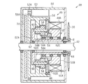
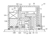
- Sectional drawing of the drive unit for bicycles of FIG. The schematic diagram which shows the rotation direction of each component of the planetary gear mechanism of FIG.
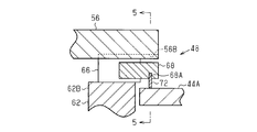
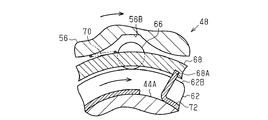
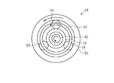
- the expanded sectional view of the power switching mechanism of FIG. FIG. 5 is a sectional view taken along line 5-5 in FIG. 4; Sectional drawing when the crankshaft of FIG. 5 rotates in the reverse rotation direction.
- Sectional drawing when the ring gear and carrier of the planetary gear mechanism of FIG. 5 rotate integrally in the normal rotation direction.
- the expanded sectional view of the power switching mechanism of FIG. FIG. 12 is a sectional view taken along line 12-12 in FIG. 11; Sectional drawing when the crankshaft of FIG. 12 rotates in the reverse rotation direction.
- the bicycle 10 includes a frame 12, a handle bar 14, a front wheel 16, a rear wheel 18, a drive mechanism 20, a battery unit 22, and a drive unit 40.
- the drive mechanism 20 includes left and right crank arms 24, left and right pedals 26, a front sprocket 30, a rear sprocket 32, and a chain 34.
- the left and right crank arms 24 are rotatably attached to the frame 12 via a crankshaft 42 of the drive unit 40.
- the pedal 26 is attached to the crank arm 24 so as to be rotatable around a pedal shaft 28.
- the front sprocket 30 is connected to the output unit 64 (see FIG. 2) of the drive unit 40.
- the front sprocket 30 is provided coaxially with the crankshaft 42.
- the rear sprocket 32 is rotatably mounted around the axle 18A of the rear wheel 18.
- the chain 34 is wound around the front sprocket 30 and the rear sprocket 32.
- the battery unit 22 includes a battery 36 and a battery holder 38 for detachably attaching the battery 36 to the frame 12.
- the battery 36 includes one or a plurality of battery cells.
- the battery 36 is constituted by a secondary battery.
- the battery 36 is electrically connected to the drive unit 40 and supplies power to the drive unit 40.
- the drive unit 40 includes a planetary gear mechanism 46, a power switching mechanism 48, and a first motor 50.
- the drive unit 40 can also include a crankshaft 42, a housing 44, and a second motor 52.
- the housing 44 houses a planetary gear mechanism 46, a power switching mechanism 48, a first motor 50, and a second motor 52.
- the housing 44 supports the crankshaft 42 to be rotatable.
- the crankshaft 42 is provided through the housing 44.
- the planetary gear mechanism 46 includes a sun gear 54, a ring gear 56, a plurality of planetary gears 58, a plurality of planetary pins 60, and a planet carrier (sometimes simply referred to as a carrier) 62.
- the ring gear 56 functions as an input body to which rotation of the crankshaft 42 is input.
- the carrier 62 functions as an output body that outputs the rotation of the planetary gear mechanism 46 to the outside.
- the sun gear 54 functions as a transmission body.
- the sun gear 54 is disposed coaxially with the crankshaft 42 around the crankshaft 42.
- the ring gear 56 is disposed outside the sun gear 54 in the radial direction of the crankshaft 42.
- the ring gear 56 is disposed coaxially with the crankshaft 42 around the crankshaft 42. Therefore, the ring gear 56 is disposed coaxially with the sun gear 54 around the sun gear 54.
- the crankshaft 42 is connected to the inner periphery (center portion) of the ring gear 56 by, for example, spline fitting or press fitting.
- the rotation of the crankshaft 42 is input to the ring gear 56, and the ring gear 56 rotates integrally with the crankshaft 42.
- the plurality of planetary gears 58 are disposed between the sun gear 54 and the ring gear 56.
- Each planetary gear 58 includes a large diameter portion 58A and a small diameter portion 58B.
- the outer peripheral gear of the large diameter portion 58 ⁇ / b> A is disposed in a portion facing the outer periphery of the sun gear 54 and meshed with the sun gear 54.
- the outer peripheral gear of the small diameter portion 58 ⁇ / b> B is disposed at a portion facing the inner periphery of the ring gear 56 and meshed with the ring gear 56.
- a planetary gear constituted by a normal single gear may be used.
- the plurality of planetary pins 60 respectively penetrate the planetary gear 58 in the axial direction.
- Each planetary pin 60 supports each planetary gear 58 rotatably. Both ends of each planetary pin 60 are rotatably supported by a carrier 62. As long as both ends of each planetary pin 60 are rotatably supported by the carrier 62, each planetary pin 60 may be supported by each planetary gear 58 so as not to rotate. As long as each planetary pin 60 supports each planetary gear 58 in a rotatable manner, both ends of each planetary pin 60 may be supported by the carrier 62 so as not to rotate.
- the carrier 62 is arranged around the crankshaft 42 and coaxially with the crankshaft 42.
- the carrier 62 rotatably holds a plurality of planetary gears 58 via a plurality of planetary pins 60. Therefore, the plurality of planetary gears 58 revolve around the sun gear 54 between the sun gear 54 and the ring gear 56.
- the carrier 62 includes a first carrier 62A that supports one end of the plurality of planetary pins 60, and a second carrier 62B that supports the other end of the plurality of planetary pins 60.
- the first carrier 62A faces the end of the small diameter portion 58B of each planetary gear 58 in the axial direction
- the second carrier 62B faces the end of the large diameter portion 58A of each planetary gear 58.
- the first carrier 62A and the second carrier 62B are coupled so as not to move relative to each other, and rotate integrally.
- the first carrier 62A and the second carrier 62B may be integrally formed.
- the first carrier 62A includes a cylindrical connecting portion 62C arranged in a space formed between the inner periphery of the sun gear 54 and the crankshaft 42.
- An output unit 64 is connected to the end of the coupling unit 62C.
- One end of the output part 64 is accommodated in the housing 44, and the other end is exposed from the housing 44.
- a bolt B is screwed into the inner periphery of the portion of the output portion 64 exposed from the housing 44.
- the front sprocket 30 is supported by the spline so as not to rotate in the circumferential direction of the output unit 64.
- the front sprocket 30 is attached to the output unit 64 by a bolt B so as not to move in the axial direction.
- the output part 64 may be formed integrally with the connecting part 62C.
- the first motor 50 is disposed coaxially with the crankshaft 42 around the crankshaft 42.
- the first motor 50 is disposed at a position adjacent to the planetary gear mechanism 46 in the axial direction of the crankshaft 42.
- the first motor 50 is disposed between the planetary gear mechanism 46 and the front sprocket 30 in the axial direction of the crankshaft 42.
- the first motor 50 is an inner rotor type motor, and includes a stator 50A supported by the housing 44 and a rotor 50B disposed on the inner peripheral side of the stator 50A.
- the end of the sun gear 54 is attached to the end of the rotor 50B in the axial direction. That is, the sun gear 54 is formed integrally with the output shaft of the first motor 50.
- the rotor 50B and the sun gear 54 can rotate with respect to the crankshaft 42.
- the first motor 50 transmits torque to the sun gear 54 and controls the rotation of the sun gear 54.
- the stator 50 ⁇ / b> A is fixed to the housing 44.
- the rotating shaft of the second motor 52 is disposed away from the crankshaft 42 in the radial direction of the crankshaft 42.
- the output gear 52 ⁇ / b> A of the second motor 52 is meshed with a gear 56 ⁇ / b> A formed on the outer periphery of the ring gear 56.
- the second motor 52 transmits torque to the ring gear 56 via the gear 56A.
- a one-way clutch can be provided in the power transmission path between the rotation shaft of the second motor 52 and the ring gear 56. This one-way clutch transmits the rotation of the second motor 52 to the ring gear 56, but does not transmit the rotation of the ring gear 56 when the crankshaft 42 rotates in the single rotation direction to the second motor 52. Composed.
- the power switching mechanism 48 is disposed between the carrier 62 and the ring gear 56.
- the outer periphery of the second carrier 62B and the inner periphery of the ring gear 56 are in the radial direction. It is arrange
- the power switching mechanism 48 includes a plurality of rolling elements 66, a retainer 68 that holds the plurality of rolling elements 66, a first urging member 70 (see FIG. 5), and a second urging member 72.
- the plurality of rolling elements 66 are arranged inside a groove 56 ⁇ / b> B formed on the inner periphery of the ring gear 56.
- the depth of the groove 56B is different in the circumferential direction.
- the groove 56B becomes shallower from the intermediate portion in the circumferential direction toward both ends.
- the first urging member 70 is attached to the groove 56B and the retainer 68.
- the first urging member 70 applies a force toward the one end of the groove 56 ⁇ / b> B to the plurality of rolling elements 66.
- the direction of the force applied to the rolling element 66 by the first urging member 70 is the direction opposite to the rotation direction of the crankshaft 42 (reverse rotation direction) when the bicycle 10 moves forward.
- the second urging member 72 is an annular spring member.
- the second urging member 72 is a so-called slide spring.
- the second urging member 72 is fitted into a cylindrical support portion 44 ⁇ / b> A having an annular portion provided inside the housing 44.
- the support portion 44 ⁇ / b> A extends from the inner wall of the housing 44.
- One end and the other end in the circumferential direction of the second urging member 72 are separated from each other.
- One end of the second urging member 72 is fitted in a groove 68 ⁇ / b> A formed in the retainer 68.
- the second urging member 72 is slidably supported by the support portion 44A.
- the second urging member 72 applies a force toward the other end of the groove 56 ⁇ / b> B to the rolling element 66 when rotation in the other direction (for example, reverse direction) is input from the crankshaft 42 to the ring gear 56.
- the direction of the force applied by the second urging member 72 to the plurality of rolling elements 66 is equal to the direction of the rotation direction (forward rotation direction) of the crankshaft 42 when the bicycle 10 moves forward.
- the second urging member 72 applies a force toward the rolling element 66 toward one end of the groove 56B.
- the rotation in the forward direction from the crankshaft 42 is input to the ring gear 56, the ring gear 56 rotates in the forward direction, and the rotation of the carrier 62 is in the forward direction and the ring gear 56.
- the plurality of rolling elements 66 move to a shallow portion that is one end of the groove 56B by the cooperation of the first urging member 70 and the second urging member 72, and the ring gear 56 and the carrier 62 are moved. And For this reason, the carrier 62 rotates in the forward rotation direction integrally with the ring gear 56. Until the rotation of the carrier 62 becomes faster than the rotation of the ring gear 56, the plurality of rolling elements 66 connect the ring gear 56 and the carrier 62 and rotate together.
- the drive unit 40 further includes a control unit 74.
- the control unit 74 is accommodated in the housing 44.
- the control unit 74 includes a drive circuit that drives the first motor 50 and a drive circuit that drives the second motor 52.
- the control unit 74 drives the first motor 50 and the second motor 52 using electric power supplied from the battery 36 (see FIG. 1).
- the control unit 74 controls the first motor 50 and the second motor 52 based on signals input from a torque sensor and a vehicle speed sensor (not shown).
- the torque sensor is for detecting human power driving force.
- the torque sensor is realized by a strain sensor provided in the ring gear 56, for example. In this case, the output from the strain sensor is given to the control unit 74 via a wireless communication device or a slip ring.
- the strain sensor is, for example, a strain gauge.
- the control unit 74 may calculate the torque based on the current applied to at least one of the first motor 50 and the second motor 52.
- the control unit 74 receives an operation signal for changing the transmission gear ratio GR of the planetary gear mechanism 46 that is the rotation number output from the planetary gear mechanism 46 with respect to the rotation number input to the planetary gear mechanism 46.
- the first motor 50 is controlled so that the ratio of the rotation of the output unit 64 to the rotation of the crankshaft 42 becomes a predetermined gear ratio.
- the control unit 74 controls the second motor 52 so that the output of the second motor 52 with respect to the human driving force is increased when an operation signal for changing the assist force is input from an operation device (not shown). To do.
- the control unit 74 and the first motor 50 and the second motor 52 may be connected via a conductor, for example.
- the controller 74 transmits the torque in the reverse direction to the sun gear 54 by driving the first motor 50.
- the rotation of the sun gear 54 accelerates the rotation speed of the planetary gear 58 that rotates around the sun gear 54.
- the rotational speed of the carrier 62 also increases, and the gear ratio GR increases.
- the control unit 74 can also control the gear ratio GR, that is, the rotational speed of the sun gear 54 to change stepwise. It is also possible to connect the control unit 74 and an external device wirelessly or by wire, and change the number and size of the gear ratio GR using this external device.
- the external device is, for example, a cycle computer or a personal computer.
- the controller 74 transmits the torque in the forward direction to the carrier 62 by driving the second motor 52. As a result, an assist force is applied to the torque input from the crankshaft 42 and output from the planetary gear mechanism 46.
- the rotation input to the planetary gear mechanism 46 when the sun gear 54 does not rotate relative to the housing 44. Is decelerated and output.
- the power switching mechanism 48 rotates the carrier 62 and the ring gear 56 integrally when the rotation speed of the carrier 62 becomes equal to or lower than the rotation speed of the ring gear 56.
- the gear ratio GR is 1 when the control unit 74 performs control to stop the rotation of the sun gear 54 relative to the housing 44.
- the drive unit 40 has the following operations and effects.
- the drive unit 40 includes a power switching mechanism 48 that rotates the carrier 62 in the reverse rotation direction when rotation in the reverse rotation direction is input from the crankshaft 42 to the ring gear 56. Therefore, when the driver rotates the crank arm 24 in the reverse direction, torque in the reverse direction is transmitted to the ring gear 56 and the front sprocket 30. Thus, the drive unit 40 can be coaster braked. Since the power switching mechanism 48 is mechanically configured and non-electrical, the coaster brake can function regardless of the presence or absence of a battery.
- the power switching mechanism 48 when rotation in the reverse direction from the crankshaft 42 is input to the ring gear 56, connects the ring gear 56 and the carrier 98 to rotate integrally. For this reason, since the rotation of the ring gear 56 in the reverse rotation direction is changed by the planetary gear mechanism 86 and is transmitted to the carrier 98, the torque loss in the planetary gear mechanism 86 is reduced. It is preferable in terms of performance. Further, since the movement angle of the crankshaft 42 when the crankshaft 42 rotates in the reverse direction and the movement angle of the front sprocket 30 are equal, the drive unit 40 does not give the driver a sense of discomfort during coaster braking.
- the power switching mechanism 48 allows relative rotation between the ring gear 56 and the carrier 62, and connects the ring gear 56 and the carrier 62 until the rotation of the carrier 62 becomes faster than the rotation of the ring gear 56. Rotate together. For this reason, even when the supply of power to the first motor 50 is stopped, rotation can be output from the planetary gear mechanism 46. Since the drive unit 40 can stop supplying power to the first motor 50 when the gear ratio GR is 1, it supplies power to the first motor 50 and maintains the phase of the sun gear 54 with respect to the housing 44. Compared with the structure to perform, it can contribute to the consumption reduction of electric power.
- the drive unit 40 realizes the function of the coaster brake and the function of restricting the rotation of the sun gear 90 with respect to the housing 44 when the power supply to the first motor 50 is stopped by one power switching mechanism 48. ing. Therefore, the structure of the drive unit 40 can be simplified as compared with the case where these functions are realized by different mechanisms.
- the first motor 50 is arranged around the crankshaft 42 and coaxially with the crankshaft 42. For this reason, compared with the structure which arrange
- the sun gear 54 is formed integrally with the output shaft of the first motor 50. For this reason, it can contribute to the reduction of the number of parts of the drive unit 40.
- the rotating shaft of the second motor 52 is disposed away from the crankshaft 42 in the radial direction of the crankshaft 42. For this reason, compared with the case where the rotating shaft of the 2nd motor 52 is arrange
- the output unit 64 is disposed offset to the planetary gear mechanism 46 in the axial direction of the crankshaft 42. For this reason, the front sprocket 30 can be easily attached and detached as compared with the configuration in which the portion to which the front sprocket 30 is attached is disposed inside the planetary gear mechanism 46 in the axial direction of the crankshaft 42.
- the drive unit 40 includes a second motor 52 that transmits torque to the carrier 62, and a first motor 50 that transmits torque to the sun gear 54 and controls the rotation of the sun gear 54. For this reason, the change of the gear ratio GR by the first motor 50 and the change of the assist force by the second motor 52 can be performed independently. For this reason, the control according to a driving
- a drive unit 80 of the second embodiment will be described with reference to FIGS.
- the drive unit 80 includes a crankshaft 82, a housing 84, a planetary gear mechanism 86, a power switching mechanism 88, a first motor 50, a second motor 52, and a control unit 74. .
- the housing 84 houses the planetary gear mechanism 86, the power switching mechanism 88, the first motor 50, the second motor 52, and the control unit 74.
- the housing 84 supports the crankshaft 82 to be rotatable.
- the crankshaft 82 is provided through the housing 84.
- the planetary gear mechanism 86 includes a sun gear 90 that is a transmission body, a ring gear 92 that is an output body that outputs rotation of the planetary gear mechanism 86 to the outside, a plurality of planetary gears 94, a plurality of planetary pins 96, and a crankshaft 82.
- a carrier 98 which is an input body to which rotation is input is provided.
- the sun gear 90 is disposed coaxially with the crankshaft 82 around the crankshaft 82.
- the ring gear 92 is disposed coaxially with the sun gear 90 around the sun gear 90.
- An output unit 100 is connected to the ring gear 92.
- One end of the output unit 100 is accommodated in the housing 84, and the other end is exposed from the housing 84.
- a bolt B is screwed into the inner periphery of the portion of the output unit 100 exposed from the housing 84.
- the ring gear 92 and the output unit 100 may be integrally formed.
- the plurality of planetary gears 94 are disposed between the sun gear 90 and the ring gear 92.
- Each planetary gear 94 includes a large diameter portion 94A and a small diameter portion 94B.
- the outer peripheral gear of the large-diameter portion 94 ⁇ / b> A is disposed at a portion facing the outer periphery of the sun gear 90 and meshed with the sun gear 90.
- the outer peripheral gear of the small diameter portion 94 ⁇ / b> B is disposed at a portion facing the inner periphery of the ring gear 92 and meshed with the ring gear 92.
- the planetary gear 94 having the large-diameter portion 94A and the small-diameter portion 94B is used, but a planetary gear constituted by a normal single gear may be used.
- the plurality of planetary pins 96 each penetrate the planetary gear 94 in the axial direction.
- Each planetary pin 96 supports each planetary gear 94 rotatably.
- Both end portions of each planetary pin 96 are rotatably supported by a carrier 98.
- each planetary pin 96 may be supported by each planetary gear 94 so as not to rotate.
- both ends of each planetary pin 96 may be supported by the carrier 98 so as not to rotate.
- the carrier 98 is arranged coaxially with the crankshaft 82 around the crankshaft 82.
- the carrier 98 rotatably holds a plurality of planetary gears 94 via a plurality of planetary pins 96. Therefore, the plurality of planetary gears 94 revolve around the sun gear 90 between the sun gear 90 and the ring gear 92.
- the carrier 98 includes a first carrier 98A that supports one end of the plurality of planetary pins 96, and a second carrier 98B that supports the other end of the plurality of planetary pins 96.
- the first carrier 98A faces the end of the small diameter portion 94B of the planetary gear 94
- the second carrier 98B faces the end of the large diameter portion 94A of the planetary gear 94.
- the first carrier 98A and the second carrier 98B are coupled so as not to move relative to each other, and rotate integrally.
- the first carrier 98A and the second carrier 98B may be integrally formed.
- the inner periphery of the second carrier 98B and the outer periphery of the crankshaft 82 include opposing portions. As shown in FIG. 12, a convex portion 98D protruding toward the crankshaft 82 is formed on the inner periphery of the second carrier 98B. A first groove 82A is formed in a portion of the crankshaft 82 facing the convex portion 98D. The convex portion 98D is fitted in the first groove 82A. The size of the first groove 82A in the circumferential direction is larger than the size of the convex portion 98D in the circumferential direction. For this reason, the second carrier 98B can move relative to the crankshaft 82 by a difference between the circumferential size of the first groove 82A and the circumferential size of the convex portion 98D.
- the first motor 50 is disposed at a position adjacent to the planetary gear mechanism 86 in the axial direction of the crankshaft 82.
- the first motor 50 is disposed on the opposite side of the front sprocket 30 with respect to the planetary gear mechanism 86 in the axial direction of the crankshaft 82.
- a support portion 84A of the housing 84 is disposed between the inner periphery of the rotor 50B of the first motor 50 and the crankshaft 82.
- the support portion 84 ⁇ / b> A has a cylindrical shape and is coaxial with the crankshaft 82.
- the rotor 50B is rotatably supported by the support portion 84A.
- the rotor 50B is supported by the support portion 84A via a pair of bearings 84B.
- the end of the sun gear 90 is attached to the end of the rotor 50B in the axial direction. That is, the sun gear 90 is formed integrally with the output shaft of the first motor 50.
- the rotor 50B and the sun gear 90 can rotate with respect to the crankshaft 82.
- the first motor 50 transmits torque to the sun gear 90 and controls the rotation of the sun gear 90.
- the stator 50 ⁇ / b> A is fixed to the housing 84.
- the support portion 84 ⁇ / b> A includes a portion extending in a space formed between the inner periphery of the sun gear 90 and the crankshaft 82.
- a one-way clutch 102 is provided between the inner periphery of the sun gear 90 and the outer periphery of the support portion 84A.
- the one-way clutch 102 allows the sun gear 90 to rotate only in the single rotation direction with respect to the support portion 84A.
- the one-way clutch 102 allows the sun gear 90 to rotate only in the reverse rotation direction with respect to the support portion 84A. Therefore, the sun gear 90 cannot rotate in the normal rotation direction with respect to the support portion 84A.
- the one-way clutch 102 may be constituted by a roller clutch or a pawl type clutch.
- the output gear 52A of the second motor 52 is meshed with a gear 98C formed on the outer periphery of the second carrier 98B.
- the second motor 52 transmits torque to the carrier 98 via the gear 98C.
- a one-way clutch can be provided in the power transmission path between the rotation shaft of the second motor 52 and the carrier 98. This one-way clutch is configured to transmit the rotation of the second motor 52 to the carrier 98 but not to transmit the rotation of the carrier 98 when the crankshaft 82 rotates in one direction.
- the power switching mechanism 88 is disposed between the crankshaft 82 and the ring gear 92.
- the outer periphery of the crankshaft 82 and the inner periphery of the ring gear 92 are planetary gear mechanisms. It arrange
- the power switching mechanism 88 includes a switching unit 104 and an urging member 106.
- a second groove 92 ⁇ / b> A is formed on the inner periphery of the center portion of the ring gear 92 at a position facing the claw portion 110 of the power switching mechanism 88.
- a plurality of second grooves 92A are formed at regular intervals, for example, at regular intervals.
- the switching unit 104 is connected to the second carrier 98B, and specifically, is connected to the inner peripheral portion of the second carrier 98B.
- the switching unit 104 includes a rotation shaft 108 that is coupled to the second carrier 98B and is parallel to the axial direction of the second carrier 98B, and a claw portion 110 that is rotatably supported around the rotation shaft 108.
- the biasing member 106 applies a force to the claw portion 110 to press the one end portion 110 ⁇ / b> A of the claw portion 110 against the outer periphery of the crankshaft 82.
- a third groove 82B is formed in a portion of the crankshaft 82 where the claw portion 110 is disposed.
- crankshaft 82 moves relative to the carrier 98 in one direction (for example, the forward rotation direction).
- the end surface 82C in the reverse direction of the first groove 82A of the shaft 82 presses the convex portion 98D of the second carrier 98B.
- the crankshaft 82 and the second carrier 98B rotate integrally in the forward rotation direction.
- one end portion 110A of the claw portion 110 is pushed in a direction opposite to the direction in which the biasing member 106 is biased by a portion of the outer periphery of the crankshaft 82 where the third groove 82B is not formed. Yes.
- the other end part 110 ⁇ / b> B of the claw part 110 moves in a direction away from the second groove 92 ⁇ / b> A of the ring gear 92.
- the claw portion 110 is in contact with a portion of the outer periphery of the crankshaft 82 where the third groove 82B is not formed, and is not in contact with the inner periphery of the ring gear 92.
- the relative rotation between the carrier 98 and the ring gear 92 is allowed.
- the claw portion 110 is kept in contact with a portion of the outer periphery of the crankshaft 82 where the third groove 82B is not formed, so that the claw portion 110 is in the ring.
- claw part 110 rotates around the rotating shaft 108 so that one end part 110A of the nail
- the other end portion 110B of the claw portion 110 moves in a direction approaching the ring gear 92, fits into the second groove 92A of the ring gear 92, contacts the inner surface of the second groove 92A, and the second carrier. 98B and the ring gear 92 are connected.
- the ring gear 92 and the carrier 98 are integrally rotated in the reverse direction.
- the control unit 74 transmits the torque in the reverse rotation direction to the sun gear 90 by driving the first motor 50. Accordingly, as shown in FIG. 10, the rotation of the sun gear 90 accelerates the rotation speed of the planetary gear 94 that rotates around the sun gear 90. For this reason, the rotational speed of the ring gear 92 is also increased, and the transmission gear ratio GR is increased. Depending on the rotational speed of the sun gear 90, the transmission gear ratio GR is changed steplessly.
- the control unit 74 shown in FIG. 9 stops the supply of power to the first motor 50, the driving of the first motor 50 is stopped. Since the one-way clutch 102 is provided between the sun gear 90 and the support portion 84A, the rotation of the sun gear 90 with respect to the support portion 84A is restricted. For this reason, when the control unit 74 stops supplying power to the first motor 50, the transmission gear ratio GR is maintained at the transmission gear ratio GR corresponding to the number of gears of each component of the planetary gear mechanism 86.
- the planetary gear mechanism 86 is input to the planetary gear mechanism 86 when the sun gear 90 does not rotate with respect to the support portion 84A because the carrier 98 functions as an input unit and the ring gear 92 is connected to the output unit 64.
- the gear ratio GR when the control unit 74 stops supplying power to the first motor 50 is 1 or more, for example, 1.2 or more.
- the first motor 50 preferably changes the transmission gear ratio GR including a range of at least 1.2 to 1.5.
- the maximum value of the gear ratio GR that is changed by the first motor 50 is, for example, 3.0 or less. In other words, the first motor 50 changes the speed ratio GR within the range of 1 to 3.0.
- the drive unit 40 has the following operations and effects in addition to the effects according to (1) to (3) and (5) to (9) of the first embodiment.
- the planetary gear mechanism 86 has a gear ratio GR of 1 or more when the rotation of the first motor 50 is stopped. For this reason, compared with the planetary gear mechanism having a gear ratio GR of less than 1 when the rotation of the first motor 50 is stopped, the range of the gear ratio GR is increased without increasing the size of the first motor 50. It can be enlarged in one or more regions.
- the rotational speed of the ring gear 92 is equal to or higher than the rotational speed of the carrier 98 when the sun gear 90 does not rotate. Since the second motor 52 is connected to the carrier 98, the second motor 52 is provided when assisting force is applied, compared to a configuration in which the second motor 52 is connected to the ring gear to transmit torque. It can suppress that the rotational speed of becomes large. For this reason, it is possible to contribute to reduction of power consumption of the second motor 52.
- the present invention is not limited to the above embodiment.
- the power switching mechanism 48 of the first embodiment can be disposed between the crankshaft 42 and the carrier 62.
- a groove having a different depth in the circumferential direction is formed on one of the outer periphery of the crankshaft 42 and the inner periphery of the carrier 62, and the rolling elements are disposed inside the groove.
- the power switching mechanism 48 rotates the crankshaft 42 and the crankshaft 42 integrally, and rotates the ring gear 56 and the carrier 62 integrally.
- grooves having different depths in the circumferential direction can be formed in a portion facing the ring gear 56.
- the rolling element 66 is disposed in this groove.
- the groove 56B of the ring gear 56 can be omitted.
- the groove 56B of the ring gear 56 of the first embodiment can be changed to a groove that has a deep end in the reverse rotation direction and becomes shallower toward the normal rotation direction.
- the rolling element 66 is disposed at the end of the groove 56B in the reverse rotation direction, the ring gear 56 and the carrier 62 can be rotated relative to each other.
- a one-way clutch is provided between the sun gear 54 or the rotor 50B and the housing 44, and the rotation of the sun gear 54 relative to the housing 44 when the supply of power to the first motor 50 is stopped by the one-way clutch is regulated. You can also.
- a one-way clutch can be provided between the crankshaft 42 and the carrier 62, and the rotation of the crankshaft 42 relative to the carrier 62 can be restricted when the supply of power to the first motor 50 is stopped by the one-way clutch. .
- the power switching mechanism 48 of the first embodiment can be changed to a claw-type power switching mechanism.
- the connection between the ring gear 56 and the carrier 62 is released, and when rotation in the reverse direction is input from the crankshaft 42, the carrier 62 and the ring gear 56 are integrated. Any configuration can be adopted as long as the configuration rotates in the reverse direction.
- the one-way clutch 102 of 2nd Embodiment can also be provided between the rotor 50B and the support part 84A.
- the one-way clutch 102 can be provided between the rotor 50B and a portion of the housing 84 other than the support portion 84A.
- the one-way clutch 102 of the second embodiment can be omitted.
- the rotational phase of the sun gear 90 relative to the housing 84 is maintained by controlling the first motor 50 not to rotate.
- the power switching mechanism 88 of 2nd Embodiment can also be provided between the crankshaft 82 and the output part 100, as FIG. 14 shows.
- a second groove is formed in the output unit 100, and the switching unit 104 is disposed at a portion where the inner periphery of the output unit 100 and the outer periphery of the crankshaft 82 face each other.
- each embodiment can also drive the 1st motor 50 to a normal rotation direction.
- the groove 56B of the ring gear 56 of the first embodiment is changed to a groove whose end in the reverse rotation direction is deep and becomes shallower toward the normal rotation direction.
- the one-way clutch 102 of the second embodiment is not provided.
- the first motor 50 of each embodiment can be disposed outside the crankshafts 42 and 82 in the radial direction.
- stepped gears arranged coaxially with the crankshafts 42 and 82 are used as the sun gears 54 and 90.
- the first motor 50 in each embodiment may be an outer rotor type motor in which the rotor 50B is arranged around the stator 50A.
- the sun gears 54 and 90 of each embodiment and the output shaft of the first motor 50 may be configured separately, and the sun gears 54 and 90 and the output shaft of the first motor 50 may be connected by spline fitting or the like. it can.
- the 2nd motor 52 of each embodiment can also be arrange
- FIG. The second motor 52 in each embodiment can be omitted.
- the second motor 52 of the first embodiment can be connected to the ring gear 56. Also, the second motor 52 of the second embodiment can be connected to the carrier 98. In short, the second motor 52 can be connected to either the input body or the output body of the planetary gear mechanisms 46 and 86.
- crankshafts 42 and 82 may be omitted from the drive units 40 and 80 of each embodiment, and a crankshaft separate from the drive units 40 and 80 may be attached.
- at least one of the first motor 50 and the second motor 52 can be provided outside the housings 44 and 84.
- a reduction mechanism may be provided between the crankshafts 42 and 82 and the carriers 62 and 98 in the embodiments, or between the ring gears 56 and 92 and the front sprocket 30.
- This reduction mechanism may be realized by at least two or more gears, or may be realized by a planetary gear mechanism.
- the planetary gear mechanisms 46 and 86 of the embodiments may be planetary gear mechanisms in which the input body is a carrier, the output body is a sun gear, and the transmission body is a ring gear.
- the planetary gear mechanisms 46 and 86 of each embodiment may be planetary gear mechanisms in which the input body is a sun gear, the output body is a carrier, and the transmission body is a ring gear.
- the planetary gear mechanisms 46 and 86 of each embodiment can be planetary gear mechanisms in which the input body is a ring gear, the output body is a sun gear, and the transmission body is a carrier.
- this planetary gear mechanism the rotation direction of the ring gear and the rotation direction of the sun gear are different. For this reason, a transmission gear for changing the rotation direction is provided between the sun gear and the front sprocket 30.
- the planetary gear mechanisms 46 and 86 of each embodiment can be planetary gear mechanisms in which the input body is a sun gear, the output body is a ring gear, and the transmission body is a carrier.
- this planetary gear mechanism the rotation direction of the sun gear and the rotation direction of the ring gear are different. For this reason, a transmission gear for changing the rotation direction is provided between the ring gear and the front sprocket 30.
- crankshafts 42 and 82, the sun gears 54 and 90, the carriers 62 and 98, or the ring gears 56 and 92 may be configured separately.
- the connecting portion 62C of the first embodiment can be configured separately from the first carrier 62A, and can be connected and rotated together by spline fitting or press-fitting.
- portion where the second groove 92A of the ring gear 92 of the second embodiment is formed is configured separately from the outer peripheral portion of the ring gear 92, and is connected to each other by spline fitting or press-fitting to rotate integrally. Can be made.
- the rotation direction (forward rotation direction) of the crankshaft when the bicycle 10 moves forward is the first rotation direction
- the reverse rotation direction is the second rotation direction, but may be opposite.
- Embodiments and modifications may be combined or replaced as appropriate. The effects obtained by such combinations or substitutions will be understood by those skilled in the art from the disclosure of the present specification and drawings.
- This invention is not limited to what was illustrated.
- the illustrated features should not be construed as essential to the invention, and the subject matter of the invention may reside in fewer features than all the features of the specific embodiments disclosed.
Landscapes
- Engineering & Computer Science (AREA)
- Chemical & Material Sciences (AREA)
- Combustion & Propulsion (AREA)
- Mechanical Engineering (AREA)
- Transportation (AREA)
- General Engineering & Computer Science (AREA)
- Retarders (AREA)
- Structure Of Transmissions (AREA)
Abstract
Description
本発明に従う自転車用ドライブユニットの一形態は、遊星歯車機構と、第1のモータと、動力切替機構とを含み、前記遊星歯車機構は、クランク軸の回転が入力される入力体、前記遊星歯車機構の回転を外部に出力する出力体、および伝達体を備え、前記第1のモータは、前記伝達体の回転を制御し、前記出力体は、前記クランク軸から第1回転方向の回転が前記入力体に入力されるとき、前記第1回転方向に応じた方向に回転し、前記動力切替機構は、前記クランク軸から第2回転方向の回転が前記入力体に入力されるとき、前記出力体を前記第2回転方向に応じた方向に回転させる。
いくつかの例では、前記動力切替機構は、前記クランク軸から前記第1回転方向の回転が前記リングギアに入力され、前記キャリアの回転が前記リングギアの回転よりも速いとき、前記リングギアと前記キャリアとの相対回転を許容する。
いくつかの例では、前記リングギアおよび前記キャリアは、前記リングギアの内周と前記キャリアの外周とが前記遊星歯車機構の径方向において対向する部分を含み、前記動力切替機構は、前記リングギアの内周と前記キャリアの外周とが対向する部分に配置される。
いくつかの例では、前記動力切替機構は、第1の付勢部材、第2の付勢部材、および、前記遊星歯車機構が設けられるハウジングをさらに含み、前記第1の付勢部材は、前記転動体に前記溝の一端に向かう力を付与し、前記第2の付勢部材は、前記ハウジングに摺動可能に支持され、前記クランク軸から前記第2回転方向の回転が前記入力体に入力されるとき、前記転動体に前記溝の他端に向かう力を付与する。
いくつかの例では、前記動力切替機構の少なくとも一部は、前記リングギアと、前記キャリアまたは前記クランク軸との間に配置される。
いくつかの例では、前記第1のモータは、前記クランク軸まわりにおいて前記クランク軸と同軸に配置される。
いくつかの例では、前記出力体と接続され、かつ、フロントスプロケットを取り付け可能な出力部をさらに備える。
いくつかの例では、前記出力体または前記入力体にトルクを伝達する第2のモータをさらに備える。
いくつかの例では、前記第1のモータおよび前記第2のモータを制御する制御部をさらに備える。
図1を参照して、自転車用ドライブユニットを搭載する自転車の構成を説明する。
自転車10は、フレーム12、ハンドルバー14、前輪16、後輪18、駆動機構20、バッテリユニット22、および、ドライブユニット40を備えている。
リングギア56は、サンギア54よりもクランク軸42の径方向の外側に配置されている。リングギア56は、クランク軸42のまわりにおいてクランク軸42と同軸に配置されている。このため、リングギア56は、サンギア54のまわりにおいてサンギア54と同軸に配置されている。クランク軸42は、例えば、スプライン嵌合または圧入等によりリングギア56の内周(中心部)に接続されている。クランク軸42の回転はリングギア56に入力され、リングギア56は、クランク軸42と一体的に回転する。
(1)ドライブユニット40は、クランク軸42から逆転方向の回転がリングギア56に入力されるとき、キャリア62を逆転方向に回転させる動力切替機構48を備えている。このため、運転者がクランクアーム24を逆転方向に回転させたとき、リングギア56およびフロントスプロケット30に逆転方向のトルクが伝達される。このように、ドライブユニット40はコースターブレーキング可能である。動力切替機構48は機械的に構成されており非電気式であるので、バッテリの有無に関係なく、コースターブレーキを機能させることができる。
(7)第2のモータ52の回転軸は、クランク軸42の径方向にクランク軸42から離れて配置される。このため、第2のモータ52の回転軸をドライブユニット40のクランク軸42と同軸に配置する場合と比較して、クランク軸42の軸方向の大型化を抑制できる。
図9~図13を参照して、第2実施形態のドライブユニット80について説明する。
図9に示されるように、ドライブユニット80は、クランク軸82、ハウジング84、遊星歯車機構86、動力切替機構88、第1のモータ50、第2のモータ52、および、制御部74を備えている。
(10)遊星歯車機構86は、第1のモータ50の回転が停止しているときの変速比GRが1以上である。このため、第1のモータ50の回転が停止しているときの変速比GRが1未満の遊星歯車機構と比較して、第1のモータ50の大型化をともなわずに変速比GRの範囲を1以上の領域において大きくすることができる。
・各実施形態のサンギア54,90と第1のモータ50の出力軸とを別体に構成し、サンギア54,90と第1のモータ50の出力軸とをスプライン嵌合等により接続することもできる。
・各実施形態の第2のモータ52を省略することもできる。
・各実施形態の第1のモータ50および第2のモータ52の少なくとも一方を、ハウジング44,84の外部に設けることもできる。
・各実施形態の遊星歯車機構46,86を入力体がサンギアであり、出力体がキャリアであり、伝達体がリングギアである遊星歯車機構にすることもできる。
実施形態および変形例は適宜組合せまたは置換してもよい。こうした組合せまたは置換によって得られる作用効果は本願明細書および図面の開示から当業者であれば理解できるであろう。本発明は、例示したものに限定されるものではない。例えば、例示した特徴が本発明にとって必須であると解釈されるべきでなく、本発明の主題は、開示した特定の実施形態の全ての特徴より少ない特徴に存在することがある。
30 フロントスプロケット
40 ドライブユニット
42 クランク軸
44 ハウジング
46 遊星歯車機構
48 動力切替機構
50 第1のモータ
52 第2のモータ
54 サンギア
56 リングギア
56B 溝
58 プラネタリギア
62 キャリア
64 出力部
66 転動体
68A 溝
70 第1の付勢部材
72 第2の付勢部材
74 制御部
80 ドライブユニット
82 クランク軸
82A 第1の溝
84 ハウジング
86 遊星歯車機構
88 動力切替機構
90 サンギア
92 リングギア
92A 第2の溝
94 プラネタリギア
98 キャリア
98D 凸部
100 出力部
102 ワンウェイクラッチ
104 切替部
108 回転軸
110 爪部
106 付勢部材
Claims (25)
- 遊星歯車機構と、
第1のモータと、
動力切替機構とを含み、
前記遊星歯車機構は、クランク軸の回転が入力される入力体、前記遊星歯車機構の回転を外部に出力する出力体、および伝達体を備え、
前記第1のモータは、前記伝達体の回転を制御し、
前記出力体は、前記クランク軸から第1回転方向の回転が前記入力体に入力されるとき、前記第1回転方向に応じた方向に回転し、
前記動力切替機構は、前記クランク軸から第2回転方向の回転が前記入力体に入力されるとき、前記出力体を前記第2回転方向に応じた方向に回転させる自転車用ドライブユニット。 - 前記動力切替機構は、前記クランク軸から前記第2回転方向の回転が前記入力体に入力されるとき、前記入力体と前記出力体とを連結して一体的に回転させる、請求項1に記載の自転車用ドライブユニット。
- 前記入力体は、リングギアであり、
前記出力体は、キャリアであり、
前記伝達体は、サンギアである、請求項1または2に記載の自転車用ドライブユニット。 - 前記動力切替機構は、前記クランク軸から前記第1回転方向の回転が前記リングギアに入力され、前記キャリアの回転が前記リングギアの回転よりも速いとき、前記リングギアと前記キャリアとの相対回転を許容する、請求項3に記載の自転車用ドライブユニット。
- 前記動力切替機構は、前記クランク軸から前記第1回転方向の回転が前記リングギアに入力されたとき、前記キャリアの回転が前記リングギアの回転よりも速くなるまでは、前記リングギアと前記キャリアとを連結して一体的に回転させる、請求項3または4に記載の自転車用ドライブユニット。
- 前記動力切替機構の少なくとも一部は、前記リングギアまたは前記クランク軸と、前記キャリアとの間に配置される、請求項3~5のいずれか一項に記載の自転車用ドライブユニット。
- 前記リングギアおよび前記キャリアは、前記リングギアの内周と前記キャリアの外周とが前記遊星歯車機構の径方向において対向する部分を含み、
前記動力切替機構は、前記リングギアの内周と前記キャリアの外周とが対向する部分に配置される、請求項3~6のいずれか一項に記載の自転車用ドライブユニット。 - 前記動力切替機構は、
前記リングギアの内周および前記キャリアの外周の一方に形成され、周方向において深さの異なる溝と、
前記溝の内部に配置される転動体と、を含む請求項7に記載の自転車用ドライブユニット。 - 前記溝は、周方向の中間部から両端部に向かうにつれて浅くなる、請求項8に記載の自転車用ドライブユニット。
- 前記動力切替機構は、第1の付勢部材、第2の付勢部材、および、前記遊星歯車機構が設けられるハウジングをさらに含み、
前記第1の付勢部材は、前記転動体に前記溝の一端に向かう力を付与し、
前記第2の付勢部材は、前記ハウジングに摺動可能に支持され、前記クランク軸から前記第2回転方向の回転が前記入力体に入力されるとき、前記転動体に前記溝の他端に向かう力を付与する、請求項9に記載の自転車用ドライブユニット。 - 前記入力体は、キャリアであり、
前記出力体は、リングギアであり、
前記伝達体は、サンギアである、請求項1に記載の自転車用ドライブユニット。 - 前記動力切替機構の少なくとも一部は、前記リングギアと、前記キャリアまたは前記クランク軸との間に配置される、請求項11に記載の自転車用ドライブユニット。
- 前記クランク軸および前記リングギアは、前記クランク軸の外周と前記リングギアの内周とが前記遊星歯車機構の径方向において対向する部分を含み、
前記動力切替機構は、前記リングギアの内周と前記クランク軸の外周とが対向する部分に配置される、請求項12に記載の自転車用ドライブユニット。 - 前記動力切替機構は、前記クランク軸の外周と前記リングギアの内周とが対向する前記部分に配置される切替部を備え、
前記切替部は、前記キャリアに連結されて前記キャリアの軸方向に平行な回転軸と、前記回転軸に回転可能に支持される爪部とを備え、
前記切替部は、前記クランク軸が前記第1回転方向に回転するとき、前記爪部が前記クランク軸および前記リングギアの少なくとも一方から離れ、前記クランク軸が前記第2回転方向に回転するとき、前記爪部が前記回転軸まわりで回転することにより、前記爪部と前記クランク軸および前記リングギアとが接触して前記キャリアと前記リングギアとを連結する、請求項13に記載の自転車用ドライブユニット。 - 前記動力切替機構は、
前記クランク軸の外周と前記キャリアの内周とが対向する部分において前記クランク軸の外周と前記キャリアの内周の一方に形成される凸部と、
前記クランク軸の外周と前記キャリアの内周とが対向する部分において前記クランク軸の外周と前記キャリアの内周の他方に形成され、前記キャリアが前記リングギアに対して移動可能になるように前記凸部を収容する第1の溝と、
前記リングギアの内周において前記クランク軸の外周と対向する部分に形成される第2の溝と、
前記爪部に力を付与する付勢部材とをさらに含み、
前記付勢部材は、前記爪部に前記クランク軸の外周に押さえつける力を付与し、
前記クランク軸が前記第1回転方向に回転するとき、前記クランク軸が前記キャリアに対して前記第1回転方向に相対移動することによって、前記爪部は前記リングギアの前記第2の溝から外れるように回転して、前記リングギアから離れ、
前記クランク軸が前記第2回転方向に回転するとき、前記クランク軸が前記キャリアに対して前記第2回転方向に相対移動することによって、前記爪部は前記リングギアの前記第2の溝に入るように回転して、前記リングギアの前記第2の溝に嵌まり込んで前記キャリアと前記リングギアとを連結する、請求項14に記載の自転車用ドライブユニット。 - 少なくとも前記遊星歯車機構を収容するハウジングと、
前記サンギアと前記ハウジングとの間に設けられ、前記ハウジングに対して前記サンギアが単一回転方向のみに回転することを許容するワンウェイクラッチとをさらに含む、請求項11~15のいずれか一項に記載の自転車用ドライブユニット。 - 少なくとも前記遊星歯車機構を収容するハウジングと、
前記第1のモータの出力軸またはロータと前記ハウジングとの間に設けられ、前記ハウジングに対して前記第1のモータの前記出力軸または前記ロータが単一回転方向のみに回転することを許容するワンウェイクラッチとをさらに含む、請求項11~15のいずれか一項に記載の自転車用ドライブユニット。 - 前記サンギアは、前記クランク軸まわりにおいて前記クランク軸と同軸に配置される、請求項3~17のいずれか一項に記載の自転車用ドライブユニット。
- 前記第1のモータは、前記クランク軸まわりにおいて前記クランク軸と同軸に配置される、請求項2~18のいずれか一項に記載の自転車用ドライブユニット。
- 前記サンギアは、前記第1のモータの出力軸と一体的に形成される、請求項18を引用する請求項19に記載の自転車用ドライブユニット。
- 前記出力体と接続され、かつ、フロントスプロケットを取り付け可能な出力部をさらに備える、請求項1~20のいずれか一項に記載の自転車用ドライブユニット。
- 前記クランク軸をさらに備える、請求項1~21のいずれか一項に記載の自転車用ドライブユニット。
- 前記出力体または前記入力体にトルクを伝達する第2のモータをさらに備える、請求項1~22のいずれか一項に記載の自転車用ドライブユニット。
- 前記第2のモータの回転軸は、前記クランク軸の径方向に前記クランク軸から離れて配置される、請求項23に記載の自転車用ドライブユニット。
- 前記第1のモータおよび前記第2のモータを制御する制御部をさらに備える、請求項23または24に記載の自転車用ドライブユニット。
Priority Applications (3)
| Application Number | Priority Date | Filing Date | Title |
|---|---|---|---|
| US15/528,729 US20170274963A1 (en) | 2014-12-25 | 2015-12-24 | Drive unit for bicycle |
| DE112015005797.8T DE112015005797B4 (de) | 2014-12-25 | 2015-12-24 | Antriebseinheit für ein Fahrrad |
| CN201580063715.4A CN107000809A (zh) | 2014-12-25 | 2015-12-24 | 自行车用驱动单元 |
Applications Claiming Priority (2)
| Application Number | Priority Date | Filing Date | Title |
|---|---|---|---|
| JP2014262351A JP6209508B2 (ja) | 2014-12-25 | 2014-12-25 | 自転車用ドライブユニット |
| JP2014-262351 | 2014-12-25 |
Publications (1)
| Publication Number | Publication Date |
|---|---|
| WO2016104564A1 true WO2016104564A1 (ja) | 2016-06-30 |
Family
ID=56150577
Family Applications (1)
| Application Number | Title | Priority Date | Filing Date |
|---|---|---|---|
| PCT/JP2015/085939 Ceased WO2016104564A1 (ja) | 2014-12-25 | 2015-12-24 | 自転車用ドライブユニット |
Country Status (6)
| Country | Link |
|---|---|
| US (1) | US20170274963A1 (ja) |
| JP (1) | JP6209508B2 (ja) |
| CN (1) | CN107000809A (ja) |
| DE (1) | DE112015005797B4 (ja) |
| TW (1) | TW201623089A (ja) |
| WO (1) | WO2016104564A1 (ja) |
Cited By (2)
| Publication number | Priority date | Publication date | Assignee | Title |
|---|---|---|---|---|
| EP3395663A1 (de) * | 2017-04-24 | 2018-10-31 | Oechsler AG | Elektromotorischer fahrradzusatzantrieb mit stufenlos variabler übersetzung |
| CN116902126A (zh) * | 2023-09-12 | 2023-10-20 | 金华澳特玛科技有限公司 | 双磁型动力电机及其电动自行车 |
Families Citing this family (16)
| Publication number | Priority date | Publication date | Assignee | Title |
|---|---|---|---|---|
| BE1022240B1 (fr) * | 2014-09-02 | 2016-03-04 | E2 Drives Sa | Groupe motopropulseur pour un vehicule a pedales |
| EP4368487A3 (en) * | 2016-12-23 | 2024-07-17 | intuEdrive BV | Hybrid powertrain for a pedal vehicle and control unit therefor |
| CN106864658B (zh) * | 2017-04-07 | 2022-03-22 | 苏州盛亿电机有限公司 | 具有倒刹失效保护功能的电动自行车中轴倒刹机构 |
| BE1025518B1 (fr) * | 2017-08-30 | 2019-04-03 | E2 Drives Sa | Groupe motopropulseur |
| CN109693496B (zh) * | 2017-10-24 | 2024-01-23 | 广东洛梵狄智能科技有限公司 | 一种轮毂变速装置 |
| KR101961589B1 (ko) * | 2018-03-08 | 2019-03-22 | 손순영 | 변속모터와 유성기어 메카니즘을 이용한 자전거용 변속장치 |
| JP7209241B2 (ja) * | 2018-03-13 | 2023-01-20 | パナソニックIpマネジメント株式会社 | モータユニット及び電動自転車 |
| DE102018209409B4 (de) * | 2018-06-13 | 2022-01-05 | Zf Friedrichshafen Ag | Antriebsanordnung für ein Fahrrad oder Pedelec |
| DE102018217351B4 (de) * | 2018-10-10 | 2023-01-12 | Vitesco Technologies Germany Gmbh | Antriebsvorrichtung für ein Fahrrad mit einem Elektromotor und Fahrrad mit entsprechender Antriebsvorrichtung |
| EP3648257A1 (de) * | 2018-10-29 | 2020-05-06 | Werner Wirth GmbH | Steckverbinder, insbesondere für ein elektrofahrrad |
| EP3862256A1 (en) * | 2020-02-06 | 2021-08-11 | Illinois Tool Works INC. | Electric bicycle gearbox |
| DE102021208703B3 (de) * | 2021-08-10 | 2022-08-25 | Zf Friedrichshafen Ag | Antriebsanordnung für ein Fahrrad und Fahrrad |
| DE102021209279A1 (de) | 2021-08-24 | 2023-03-02 | Mahle International Gmbh | Elektrische Antriebseinrichtung für ein Fahrrad |
| DE102022205263B3 (de) | 2022-05-25 | 2023-08-24 | Zf Friedrichshafen Ag | Antriebseinrichtung für ein muskelkraftbetriebenes Fahrzeug und Mikromobilitätsfahrzeug mit dieser Antriebseinrichtung |
| CN117284406A (zh) * | 2022-06-17 | 2023-12-26 | 台达电子工业股份有限公司 | 电动助力自行车的动力模块 |
| CN116495093B (zh) * | 2023-06-29 | 2023-09-15 | 昆山唐泽新能源科技有限公司 | 一种变速花鼓 |
Citations (3)
| Publication number | Priority date | Publication date | Assignee | Title |
|---|---|---|---|---|
| JPH11171080A (ja) * | 1997-12-12 | 1999-06-29 | Shimano Inc | 自転車用変速装置 |
| JP2008285069A (ja) * | 2007-05-18 | 2008-11-27 | Bridgestone Corp | 駆動力制御装置及び電動アシスト自転車 |
| WO2013156445A1 (de) * | 2012-04-17 | 2013-10-24 | Brose Fahrzeugteile Gmbh & Co. Kommanditgesellschaft, Coburg | Antriebseinrichtung für ein elektrorad |
Family Cites Families (22)
| Publication number | Priority date | Publication date | Assignee | Title |
|---|---|---|---|---|
| JP2000153795A (ja) * | 1998-06-29 | 2000-06-06 | Yamaha Motor Co Ltd | 電動補助車両 |
| JP2002331957A (ja) * | 2001-05-09 | 2002-11-19 | Mitsubishi Automob Eng Co Ltd | 車両のフレーム構造 |
| US6871735B2 (en) * | 2001-06-26 | 2005-03-29 | Ntn Corporation | Reverse-input shutoff clutch and rotation drive device |
| JP4283167B2 (ja) * | 2001-06-26 | 2009-06-24 | Ntn株式会社 | 紙送り機構 |
| JP4036776B2 (ja) * | 2003-03-11 | 2008-01-23 | Ntn株式会社 | 電動補助自転車 |
| JP4209242B2 (ja) * | 2003-04-22 | 2009-01-14 | Ntn株式会社 | 逆入力遮断クラッチ |
| JP5230979B2 (ja) * | 2006-08-28 | 2013-07-10 | Ntn株式会社 | 駆動力正逆切替装置 |
| JP5246656B2 (ja) * | 2008-10-20 | 2013-07-24 | パナソニック株式会社 | 電動自転車 |
| DE102009045447B4 (de) * | 2008-12-11 | 2021-07-22 | Robert Bosch Gmbh | Fahrrad mit elektrischem Hilfsantrieb |
| WO2012025782A1 (de) * | 2010-08-23 | 2012-03-01 | Clean Mobile Ag | Rastenloser freilauf |
| EP2617636B1 (en) * | 2010-09-16 | 2018-01-10 | Panasonic Corporation | Electric bicycle |
| JP2012086625A (ja) * | 2010-10-18 | 2012-05-10 | Ntn Corp | 電動補助自転車 |
| JP2012086628A (ja) * | 2010-10-18 | 2012-05-10 | Ntn Corp | 電動補助自転車 |
| JP5634842B2 (ja) * | 2010-12-06 | 2014-12-03 | Ntn株式会社 | 遊星歯車機構およびこれを備えた電動補助自転車用のハブモータ装置 |
| DE102011050447B4 (de) * | 2011-05-18 | 2013-02-07 | Karsten Bettin | Getriebeeinheit mit einer oder mit zwei Gangstufen, wahlweise für Fahrräder oder für Anhängefahrräder |
| DE102011077903A1 (de) * | 2011-06-21 | 2012-12-27 | Brose Fahrzeugteile Gmbh & Co. Kg, Coburg | Antriebseinrichtung für ein Elektrorad |
| JP5649549B2 (ja) * | 2011-10-13 | 2015-01-07 | 株式会社シマノ | 自転車用駆動ユニット |
| BE1020653A4 (fr) * | 2012-04-27 | 2014-02-04 | Deleval Arthur | Groupe motopropulseur. |
| JP5202769B1 (ja) * | 2012-07-11 | 2013-06-05 | パナソニック株式会社 | 電動アシスト自転車 |
| KR101489933B1 (ko) * | 2013-08-12 | 2015-02-04 | 주식회사 하이코어 | 입력 합성 기어 시스템 |
| DE102014009833B4 (de) * | 2014-07-02 | 2016-05-19 | Ling He | Antriebseinheit für ein elektrisch unterstütztes Fahrrad. |
| US20160159431A1 (en) * | 2014-12-05 | 2016-06-09 | GM Global Technology Operations LLC | Electric cycle having pedal force-based propulsion system |
-
2014
- 2014-12-25 JP JP2014262351A patent/JP6209508B2/ja active Active
-
2015
- 2015-11-11 TW TW104137137A patent/TW201623089A/zh unknown
- 2015-12-24 US US15/528,729 patent/US20170274963A1/en not_active Abandoned
- 2015-12-24 WO PCT/JP2015/085939 patent/WO2016104564A1/ja not_active Ceased
- 2015-12-24 CN CN201580063715.4A patent/CN107000809A/zh active Pending
- 2015-12-24 DE DE112015005797.8T patent/DE112015005797B4/de active Active
Patent Citations (3)
| Publication number | Priority date | Publication date | Assignee | Title |
|---|---|---|---|---|
| JPH11171080A (ja) * | 1997-12-12 | 1999-06-29 | Shimano Inc | 自転車用変速装置 |
| JP2008285069A (ja) * | 2007-05-18 | 2008-11-27 | Bridgestone Corp | 駆動力制御装置及び電動アシスト自転車 |
| WO2013156445A1 (de) * | 2012-04-17 | 2013-10-24 | Brose Fahrzeugteile Gmbh & Co. Kommanditgesellschaft, Coburg | Antriebseinrichtung für ein elektrorad |
Cited By (3)
| Publication number | Priority date | Publication date | Assignee | Title |
|---|---|---|---|---|
| EP3395663A1 (de) * | 2017-04-24 | 2018-10-31 | Oechsler AG | Elektromotorischer fahrradzusatzantrieb mit stufenlos variabler übersetzung |
| CN116902126A (zh) * | 2023-09-12 | 2023-10-20 | 金华澳特玛科技有限公司 | 双磁型动力电机及其电动自行车 |
| CN116902126B (zh) * | 2023-09-12 | 2023-12-19 | 金华澳特玛科技有限公司 | 双磁型动力电机及其电动自行车 |
Also Published As
| Publication number | Publication date |
|---|---|
| CN107000809A (zh) | 2017-08-01 |
| US20170274963A1 (en) | 2017-09-28 |
| JP2016120847A (ja) | 2016-07-07 |
| DE112015005797B4 (de) | 2025-09-18 |
| JP6209508B2 (ja) | 2017-10-04 |
| DE112015005797T5 (de) | 2017-09-21 |
| TW201623089A (zh) | 2016-07-01 |
Similar Documents
| Publication | Publication Date | Title |
|---|---|---|
| JP6209508B2 (ja) | 自転車用ドライブユニット | |
| JP6325430B2 (ja) | 自転車用ドライブユニット | |
| US9994284B2 (en) | Bicycle assist unit | |
| TWI635021B (zh) | Bicycle drive assembly and bicycle with drive assembly | |
| JP2017132439A (ja) | 自転車用駆動装置 | |
| JP6515019B2 (ja) | 自転車用ドライブユニット | |
| TW201726482A (zh) | 自行車用驅動裝置 | |
| KR20160074765A (ko) | 허브 모터 구조체 | |
| JP2017088091A (ja) | 自転車用ドライブユニット | |
| JP2018532089A (ja) | モーター用変速機 | |
| JP2016165911A (ja) | 電動自転車 | |
| JP2016182851A (ja) | 自転車用ドライブユニット | |
| JP2017095058A (ja) | 自転車用ドライブユニット | |
| JP6820244B2 (ja) | 自転車用変速機およびこれを備える自転車用アシストシステム | |
| JP2013249060A (ja) | 自転車変速機および自転車 | |
| US20170240247A1 (en) | Coaxially situated friction-ring gear unit for a vehicle that is able to be operated using motor power and/or pedaling power | |
| EP3045756A1 (en) | Clutch device | |
| JP2018534210A (ja) | 自転車のチェーンホイールキャリアとホイールハブとの間で用いる変速機、並びにその変速機を備えた後部アクスルおよび後部ホイール | |
| JP2019183967A (ja) | 人力駆動車の回転装置 | |
| JP2015105012A (ja) | 電動車両の駆動装置 | |
| JP6343155B2 (ja) | 変速装置およびこれを備える電気自動車 | |
| US10119602B2 (en) | Power transmission apparatus | |
| KR20140111442A (ko) | 전동 차량용 변속기를 구비한 자전거 | |
| KR20140111445A (ko) | 전동 차량용 변속기 및 그를 포함하는 전동 차량 |
Legal Events
| Date | Code | Title | Description |
|---|---|---|---|
| 121 | Ep: the epo has been informed by wipo that ep was designated in this application |
Ref document number: 15873132 Country of ref document: EP Kind code of ref document: A1 |
|
| WWE | Wipo information: entry into national phase |
Ref document number: 15528729 Country of ref document: US |
|
| WWE | Wipo information: entry into national phase |
Ref document number: 112015005797 Country of ref document: DE |
|
| 122 | Ep: pct application non-entry in european phase |
Ref document number: 15873132 Country of ref document: EP Kind code of ref document: A1 |
|
| WWG | Wipo information: grant in national office |
Ref document number: 112015005797 Country of ref document: DE |